

Telex Pro Audio Group DN3601C Operators & Service Manual

Operators & Service
Manual
DN3601C
Version 3.0C
TELEX PRO AUDIO GROUP
Klark Teknik Building
Walter Nash Road, Kidderminster
Worcestershire DY11 7HJ
England
Tel: (01562)741515 Fax: (01562)745371

CONTENTS
DECLARATION OF CONFORMITY 3
INTRODUCTION 8
INSTALLATION 9
INSTRUMENT FAMILIARISATION 10
MASTER/SLAVE OPERATION 11
REFERENCE SECTION:
DETAILS OF OPERATION 13
DEFAULT/START UP 13
FADER ADJUSTMENT 13
GAIN ADJUSTMENT 13
CURVE/FADER 13
MORE EQ 14
A : B : LINK 14
UTILITIES 14
BYPASS AND RESET 14
MORE EQ MENU AND DISPLAY 15
FILTERS 15
A : B 15
IN/OUT 15
EXIT 15
FILTER ADJUST 16
NOTCH1/2 16
16
BACK 16
UTILITIES MENU 17
AUTO/Q 17
MEMORY 17
MORE... 17
EXIT 17
AUTO/Q MENU 18
AUTO GAIN 18
AUTO EQ 18
Q TYPE 18
EXIT 18
MEMORY/LOCKOUT MENU 19
RECALL 19
SAVE 19
LOCK 20
FULL 20
1

PARTIAL 20
EXIT 20
MORE... MENU 21
SLAVES 21
STAND ALONE 21
ALL 21
SLAVES 1 TO 64 21
MIDI CHAN 21
INV LCD 21
EXIT 21
TECHNICAL SPECIFICATION 22
MENU STRUCTURE 23
SERVICE INFORMATION:
FUSE SPECIFICATION 25
MIDI CONNECTIONS 26
SCHEMATIC DIAGRAMS
2

DECLARA TION OF CONFORMITY
The Directive Covered by this Conformity
89/336/EEC Electromagnetic Compatibility Directive, amended by 92/31/EEC & 93/68/EEC.
73/23/EEC Low V oltage Directive, amended by 93/68/EEC.
The Products Covered by this Declaration
Equipment T ype Product Name V ariants
Graphic Equaliser DN300 DN360, DN301, DN332
Preset Equaliser DN320 DN330
Parametric Equaliser DN405 DN410
Dynamics Processor DN500 DN504, DN510, DN514
Audio Analyser DN6000
Crossover DN800
Delay Line DN7204 DN7103
Programmable Equaliser DN3600 DN3601
Remote Control System DN3698 DN3603
Crossover DN8000
Programmable Equaliser DN4000
The Basis on which Conformity is being Declared
The Products named above and hence the V ariants thereof listed above comply with the requirements
of the above EU directives by meeting the following standards:
EN 50081-1 (EN55022 class B)
EN 50082-1 (IEC801 Part 2, 4 / ENV 50140 / ENV 50141
EN 60065.
Signed: ........................... N. G. Tembe
Authority: Head of Engineering, EVI Audio (U.K.) Plc
Date: 1st January 1997
Attention!
The attention of the specifier, purchaser , installer or user is drawn to the special limitations to use which
must be observed when these products are taken into service to maintain compliance with the above
directives. Details of these special measures and limitations to use are available on request, and are
also contained in product manuals.
3

Attention!
Cables:
This product should only be used with high quality, screened twisted pair audio cables, terminated
with metal bodied 3-pin XLR connectors. The cable should be connected to pin 1. Any other cable
type or configuration for the audio signals may result in degraded performance due to electromagnetic
interference.
Electric Fields:
Should this product be used in an electromagnetic field that is amplitude modulated by an audio
frequency signal (20Hz to 20kHz), the signal to noise ratio may be degraded. Degradation of up to
60dB at a frequency corresponding to the modulation signal may be experienced under extreme
conditions (3V/m, 90% modulation).
4

5

THANK YOU FOR USING THIS KLARK TEKNIK PRODUCT
To obtain maximum performance from this precision electronic product, please study these instructions
carefully. Installation and operating the DN3601 is not complicated, but the flexibility provided by its
operating features merits familiarisation with it's controls and connections. This unit has been prepared
to comply with the power requirements that exist in your location.
Precautions
Before connecting the unit to the mains power, ensure that the operating voltage is correct for your local
supply. Operating voltage is indicated by an adhesive label on the rear panel.
Do not install this unit in a location subjected to excessive heat, dust or mechanical vibrations.
Power Connection
Connection is made by means of an IEC standard power socket. The unit will operate off any AC
voltage between 100 Vac and 240 Vac @ 50 Hz to 60 Hz.
Before connecting this unit to the mains supply, ensure that the fuse fitted is the correct type and rating,
as indicated on the rear panel, adjacent to the fuse holder.
Safety Warning
This unit is fitted with 3-pin power socket. For safety reasons the earth lead should not be disconnected.
If you encounter a problem with earth-loops, remove the ground-lift link located inside the unit to isolate
the signal earth from the chassis earth (see Service section for details). This should be carried out by
a qualified service technician only.
To prevent shock or fire hazard, do not expose the unit to rain or moisture.
To avoid electrical shock, do not remove covers. Dangerous voltages exist inside. Refer servicing to
qualified personnel only.
6
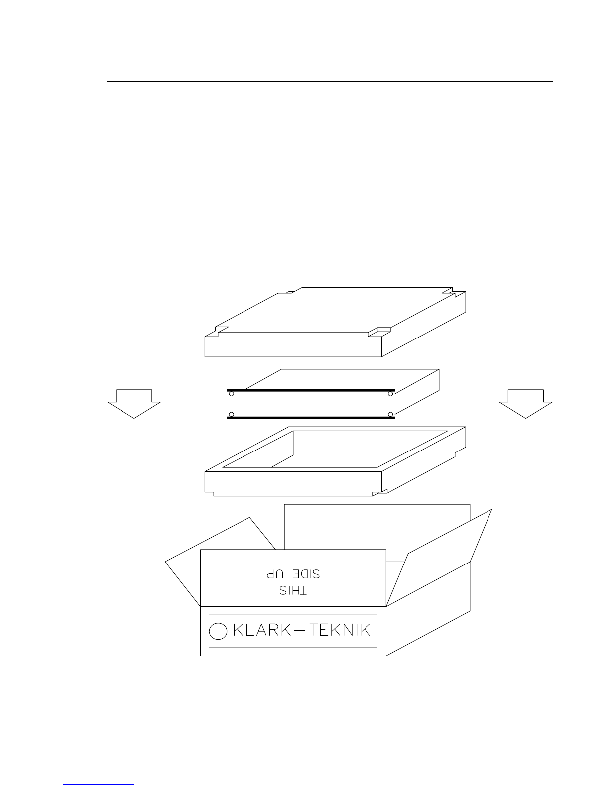
After you have unpacked the unit
Save all the packing materials - they will prove valuable should it become necessary to transport or ship
this product.
Please inspect this unit carefully for any signs of damage incurred during transportation. It has undergone
stringent quality control inspection and tests prior to packing and left the factory in perfect condition.
If, however, the unit shows any signs of damage, notify the transportation company without delay. Only
you, the consignee, may institute a claim against the carrier for damage during transportation.
If necessary, contact your supplier or as a last resort, your Klark Teknik importing agent, who will fully
co-operate under such circumstances.
7

INTRODUCTION
Designed to meet and exceed the needs of the recording, broadcast, installation and live sound
industries, the Klark Teknik DN 3601 Programmable Slave Graphic Equaliser is an extremely high
quality, digitally controlled, two-channel, third-octave equaliser that offers state-of-the-art audio
performance in a remote controlable, tamper-proof, cost effective package. The two channels may
either be used independently or linked for stereo use. To further extend the flexibility of the equaliser,
the unit also incorporates variable frequency low and high-pass filters, two notch filters with variable
frequency and depth and overall gain adjustment on each channel.
Being the ‘slave’ derivative of the Klark Teknik model DN3600, the DN3601 front panel features only
twin signal strength meters, clip LEDs, an LED numerical display and a power switch. The unit can be
controlled by a master DN3600 unit or by a suitably equipped computer or other MIDI control device.
Up to 64 DN3601 units (or mixed DN3600s and DN3601s) may be linked in a single MIDI loop via
the Pro MIDI Interface on the rear panel. The DN3601 may store up to 66 equaliser programs in its
own, internal memory and can then take full advantage of the extensive user interface of the controling
device. A 16-pin connector is provided on the DN3600 for use in conjunction with the DN60 Real
Time Spectrum Analyser enabling room analysis and equalisation to be accomplished automatically.
An extensive equalisation system can be created with central, user friendly control. Slave units may be
addressed individually or globally by the master, and will also respond to standard MIDI program
change commands.
The proprietary analogue filters are based around the Klark Teknik “MELT” hybrid filter circuits which
offer far greater headroom and dynamic range than is possible using 18-bit linear, digital systems.
Benefiting from revised circuitry, these filters are exceptionally reliable and offer greater stability than
discrete designs. They are also relatively immune to electromagnetic interference, unlike coil-based
filters. Separate supply rails are used for the digital and analogue circuitry which, in combination with
rigorous internal screening, ensures the cleanest possible audio signal path.
In order to provide maximum operational flexibility, the system includes a switchable Q mode. The Low
Q setting (Q:360) provides an accurate emulation of the industry-standard DN360 equaliser. In High
Q mode (Q:27), the performance emulates the DN27.
To maintain the optimum signal to noise ratio and headroom at all equaliser settings, the gain control acts
on the equaliser sections themselves rather than being a simple pre or post-equalisation gain stage.
Additionally, an Auto gain mode is included in the system which automatically scales the gain of the
individual equaliser bands as cut or boost is applied to reduce the risk of accidental clipping and to
maintain a safe working headroom.
Both the input and output circuitry is electronically balanced with a nominal operating level of +4dBu.
The output circuitry is based on the Midas XL3 output stage, giving exceptionally high drive capability.
A transformer option is available for both inputs and outputs.
8

Installation
The inputs and outputs are fully balanced on XLR connectors and are wired conventionally with pin 1
as ground. Because the system is fully floating, either pin 2 or pin 3 can be designated as hot so long
as the same protocol is adhered to for both the input and the output connectors.
The DN3601 is designed for use in both fixed and mobile installations where it can be mounted in a
conventional 19 inch rack occupying just 2U of height. In mobile situations where rough handling is a
possibility, it is advisable to support the rear of the unit to prevent undue stress being placed on the front
panel. Ensure that the unit has sufficient ventilation and that it is not placed directly over any device which
runs hot such as a power amplifier or console power supply.
9
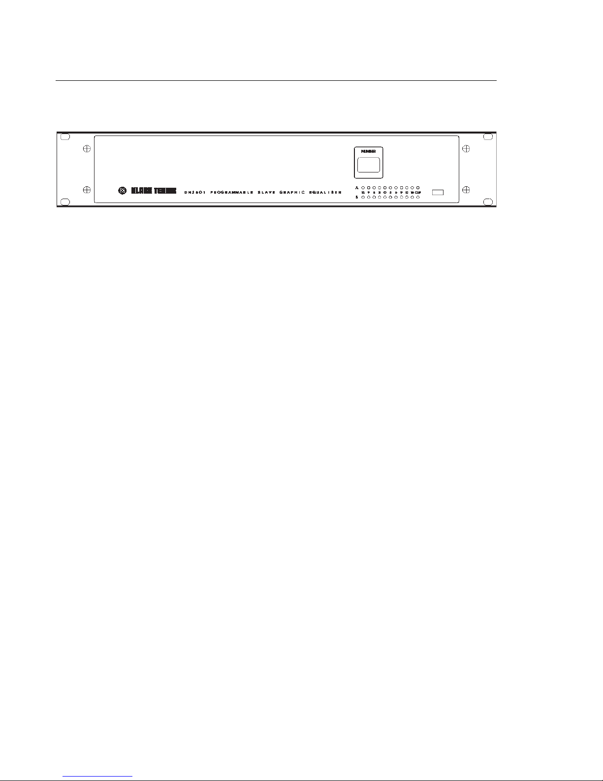
Instrument Familiarisation
Front panel functions
NUMERIC WINDOW: Displays the address number of the Slave and flashes on and off when the
unit is being addressed by an external controler, such as a DN3600.
METERS: Separate 10-segment bargraph level meters monitor the signal level in channels A and B over
the range -12dB to +15dB. The Clip warning LED monitors seven different points within the circuitry
of the DN3601 and flashes if the level at any point comes within 2dB of clipping.
POWER SWITCH: Switches the unit on and off. When the unit is off, there is a hard relay bypass which
connects the input signal directly to the output.
Rear Panel Functions
Balanced Input XLR Sockets
Balanced Output XLR Sockets
Pro MIDI XLR Connectors: These follow the same wiring convention as conventional MIDI DIN
sockets. These are used for performing system exclusive data transfer and for linking multiple units in
a master/slave configuration. See service section for wiring convention.
Voltage Selector Switch: selects between 120V and 240V operation.
IEC Mains Socket.
10
MASTER/SLAVE OPERATION
The Klark Teknik Pro MIDI Master/Slave system allows up to 65 DN3601 and DN3600 units to
be operated, either individually or together, from the front panel of a single DN3600 or a siutably
equiped computer. The system is simple to connect, simple to operate and protects itself from the
dangers of unreliable power supply and damaged connections.
Once programmed, the equaliser program memories resident in the DN3601 Slaves may be selected
via ordinary MIDI program change commands without the need for a DN3600 master unit. This
provides an economical way of managing a large installation as the slave system is both cost effective
and secure from inadvertent tampering.
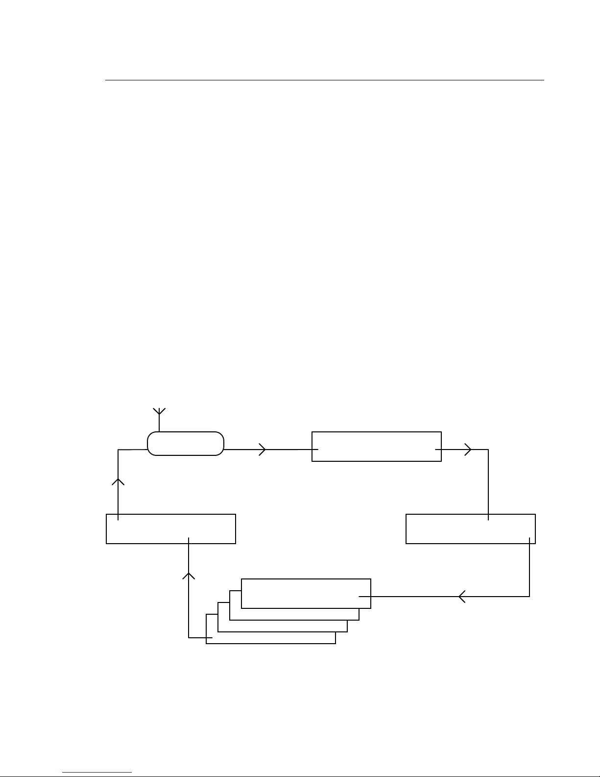
Connections.
For remote control of all parameters, any DN3601, DN3600 and computer devices must be linked in
a closed loop via their Pro MIDI interfaces - MIDI OUT to MIDI IN. Master/Slave configuration is
automatic when two or more DN3600 and/or DN3601 units linked in this way. Remote control is via
"system exclusive" messages.
Note: The loop must be closed. Each MIDI OUT must be connected to the next MIDI IN. If MIDI
program change messages from some other device are to be injected onto the Klark Teknik loop, this
must be done via a MIDI MERGE unit.
MIDI Merge
Optional
Master
SlaveSlave
Slaves
11
 Loading...