

Page 1

www.telexper.com
Quick Installation Guide
Network Video Server
Page 2
1
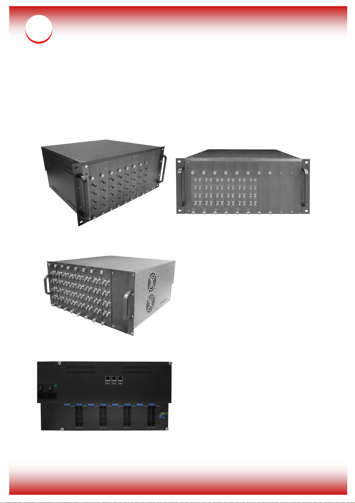
32CH/48CH/64CH Network Video Server
Model No: nVS-32 / 48 / 64
- Product Front View
nVS-32 nVS-48
nVS-64
- Product Rear View
1
Page 3
2
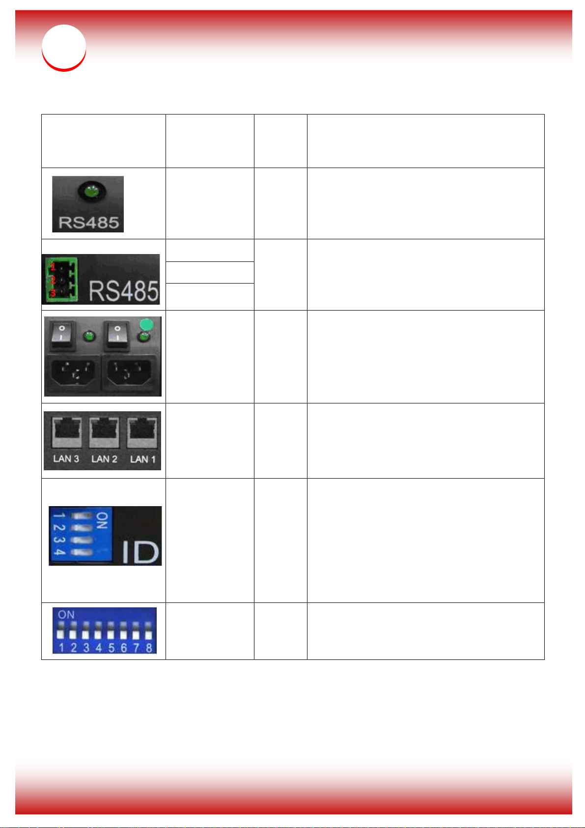
nVS32/48/64 provides dual power redundant
LAN 3 are three ports giga Ethernet
Product Front and Rear Description:
Pin or Switch
None Front
1: D- (RS485)
2: D+ (RS485)
3: GND
O: Power off
I: Power On
Product
Front or
Rear
Rear
Rear
Description
When the green light is on, it means that the
machine has been connected and RS485
function is on
Please connect the RS485 controller DT+
(D+) pin to the D+ pin of the machine, and
also the DT- (D-) pin to the D- pin of the
machine.
function, please use them at the same time.
When green light is on, it means that the
machine is operating smoothly.
3 Ports Hub
Rear
(without PoE)
Bit 1, 2, 3
On: 1 or
Rear
Off: 0
(Default: ID 0)
Bit 1-8
Rear
(Default: All On)
LAN 1 to
Hub and they could be connected to other
LAN devices together.
ID 0: 0, 0, 0/ID 1: 0, 0, 1
ID 2: 0, 1, 0/ID 3: 0, 1, 1
ID 4: 1, 0, 0/ID 5: 1, 0, 1
ID 6: 1, 1, 0/ID 7: 1, 1, 1
When the system connects over 2 nVS
machines under the same environment,
please check to switch the ID.
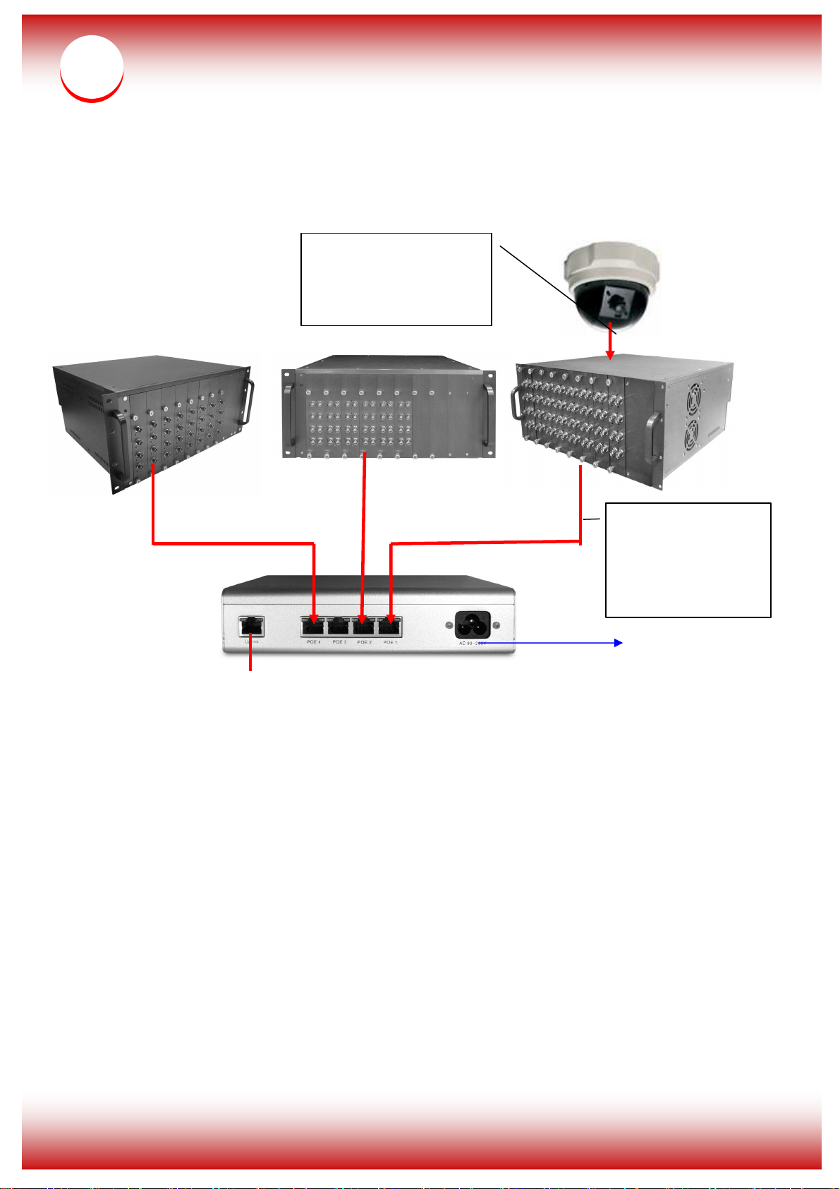
Please use the 75 Ohm coaxial video cable
to connect the camera to the video server.
2
Page 4
3
Connect Cameras by
IP CCTV Solution Configuration
using the 75 Ω
coaxial video cable
to nVS
Ω
ΩΩ
Connect the nVS
by using the
CAT-6 RJ-45
cable to PoE Hub
Power Cord
Uplink to network
3
 Loading...