

Page 1
®
Telex
Operating Instructions
Listen
Talk
Call
Mic Kill
1
Talk
PA
Headset
All Talk
Vox
Side Tone
Panel Mic
R
Volume
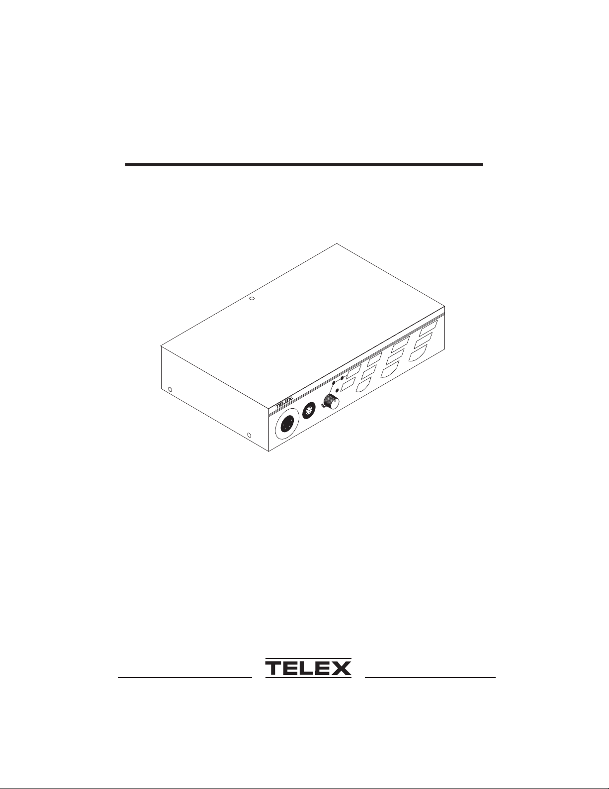
US-2000
Listen
Call
2
US-2000
User Station
®
Audiocom
Intercom
System
®
Page 2

GENERAL
The Audiocom® US-2000 is a microprocessor controlled two-channel
intercom user station, that occupies only 1/2-rack space. The US-2000
can communicate with an entire intercom system or an individual
channel, and can be expanded up to 18 channels. ES-4000 Expansion
Stations can be “daisy chained” to the US-2000 to add four channels at a
time to the intercom system. Each channel can be programmed for talk,
listen or both. The US-2000 can use mono or stereo headsets, or panel
mounted microphone. VOX operation can be selected for either headset
or panel microphone. Internal switch and jumper settings allow the unit
to be used with Clear-Com® components, if desired. Other internal
switch and jumper settings allow the unit to be uniquely configured to the
operator’s requirements.
FCC STATEMENT
This equipment uses, and can radiate radio frequency energy that may
cause interference to radio communications if not installed in accordance
with this manual. The equipment has been tested and found to comply
with the limits of a Class A computing device pursuant to Subpart J, Part
15 of FCC Rules which are designed to provide reasonable protection
against such interference when operated in a commercial environment.
Operation of this equipment in a residential area may cause interference
which the user (at his own expense) will be required to correct.
This product meets the Electromagnetic Compatibility Directive,
89/336/EEC.
OPERATION
SYSTEM POWER
The US-2000 receives power externally, in one of two ways:
· Via the
· Via
®
Clear-Com is a registered trademark of Clear-Com Intercom Systems
® Audiocom is a trademark of Telex Communications, Inc., Minneapolis, Minnesota 55420
12-15 VDC
CHN 1orCHN 2
power input jack
, intercom channel connectors
1
Page 3
PUSH
4
US-2000
Listen Listen
Mic KillHeadset
Side Tone
Call Call
PAPanel Mic
Vox
12
11 11
18
Talk Talk
PUSH
All Talk
710108 9 12 12
TELEX COMMUNICATIONS, INC. MADE IN USA
6
5
Volume
SPEAKERS
CHN 2
VOL
PGM 2
CHN 1
VOL
PGM 1
17 13161514
1 VRMS
2
LINE LEVEL
1
13
123
PROGRAM
INPUTS
-
+
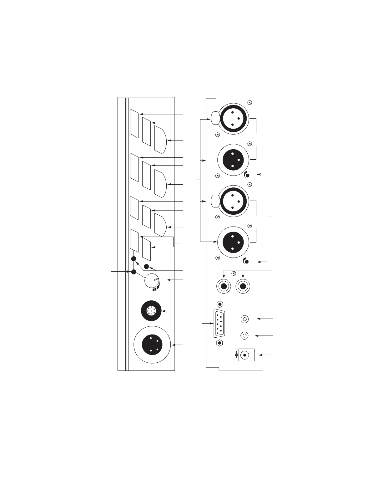
Figure 1. Front and Rear Panel Controls
2
OUT
P.A. EXP
12-15 VDC
Page 4

INITIAL US-2000 SETUP
The channel termination is initially set for balanced operation, which is
compatible with other Audiocom® equipment. If the unit is going to be
connected to Clear-Com equipment, two jumpers and one switch must
be changed as described in the section on Clear-Com Setup in this
manual.
The US-2000 is factory set to allow all channels (including those of any
attached ES-4000 units) to be heard through a single powered speaker,
such as the Audiocom® SPK-1000. If the user wants to have each
channel go to a separate powered speaker, three jumpers must be
changed as described in the section on Speaker Setup in this manual.
The headset microphone termination is initially set for unbalanced
operation. To change the headset microphone termination, refer to
Table 2 in this manual for the position of jumper J16. If the termination
requirement of a headset microphone is unknown, the recommended
setting is unbalanced.
MICROPROCESSOR FUNCTIONS
RESET: Simultaneously press
reset the US-2000 microprocessor to its power-up state.
TEST SIGNAL: Simultaneously press
microprocessor to generate 1 kHz test signal. Press any US-2000 or
ES-4000
same
other key on that unit (except
Call
key to send the test signal down that channel. Press the
Call
key to stop the test signal on that channel, then press any
All Talk
and channel 1
All Talk
andPAkeys to cause the
Listen
keys to
Call) to exit the test signal function.
EXTERNAL CONNECTIONS & CONTROLS
NOTE: The numbers refer to the callouts in Figure 1.
1. Mono Headset Connector
This connector accepts a Telex® boom-microphone headset.
2. Panel Microphone or Stereo Headset Connector
This connector accepts a Telex® gooseneck microphone (model
EGM-12N or EGM-18N) or stereo headset.
3
Page 5

3. VOLUME
Use this control to adjust the headset listen level.
4.
SIDETONE
When using a headset, this control adjusts your own voice level
heard in the earphones. To adjust the level, tap the
once to turn on the headset microphone. Then, use a small
flat-blade screwdriver to increase or decrease your voice level while
talking into the microphone.
5.
VOX
Control
Control
Headset
Level Adjustment
key
There are separate
phone. These adjust the voice level required to activate the microphone when VOX mode is on.
To adjust the headset VOX level, place the
in VOX mode (see 6 below). While talking into the headset microphone in a normal voice, use a small flat-blade screwdriver to adjust
the
VOX
control to the desired voice activation level. The
microphone key will turn from orange to green as the microphone
turns on.
Use the same procedure to adjust the panel microphone VOX level
using the
6.
Headset
The
key activates the panel microphone. Either key selects one of three
modes of microphone operation:
Latched Mode:
Momentary Mode:
Panel Mic
and
Headset
Tap the key once to turn the headset or panel microphone on.
The key will glow green. Tap the key again to turn the headset
or panel microphone off.
VOX
level controls for headset and panel micro-
Headset
key and
Panel Mic
key activates the headset microphone. The
keys
VOX
level control.
microphone key
Headset
Panel Mic
Press and hold the key to momentarily turn on the headset or
panel microphone. Release the key to turn the headset or panel
microphone off.
4
Page 6

VOX Mode:
With the headset or panel microphone off, tap the key twice to
turn on VOX mode. The key will glow orange when there is no
audio present, and green when you talk into the headset or
panel microphone. (When in VOX mode you may have to adjust
the
VOX
level.) Tap the key once to turn off VOX mode.
7.
All Talk
The All Talk function allows the user to talk on all attached channels
simultaneously. To activate this function with either the
Panel Mic
US-2000 and ES-4000 channels at once. The key will glow green.
8.
PA
The PA function allows the user to talk over a public address system
that is connected to the rear of the US-2000. With either the
set
public address system connected to the
panel of the US-2000. The key will glow green.
9.
Mic Kill
This key controls three features:
key
key
or
Panel Mic
key
selected, press and hold the
selected, press and hold thePAkey to talk on a
All Talk
P.A.
key to talk on all
output jack on the back
Headset
or
Head-
Microphone Kill Feature:
This feature sends a signal that causes the intercom stations on
a selected channel to turn off any activated microphones on that
channel. (Works with US-2000, ES-4000, SS-1000, BP1000 and
BP2000 stations.) Tap the key once to access this feature. The
key will blink green. To turn off all activated microphones on any
channel, press the
To turn off all microphones on all channels, press the
key. Tap the
Program Kill Feature:
This feature allows the program audio to be individually disabled
on each channel. Press and hold the key to access this feature.
The key will glow green and the current Program Kill status will
be displayed (when a
that channel). Press a
TalkorListen
Mic Kill
key for the desired channels.
key to exit.
Talk
key is lit, program audio is enabled on
Talk
key to enable or disable program au-
5
All Talk
Page 7

dio on that channel. Tap the
setup.
Headset Audible Call Alert Feature:
This feature will cause an audible beep in the headset whenever
there is an incoming call from any channel. Press and hold the
key to access this feature. The key will glow green and the current Headset Audible Call Alert status will be displayed (when
both
Call
keys are lit, Headset Audible Call Alert is enabled).
10.
Press either
Alert on both US-2000 channels. Tap the
feature setup.
Talk
keys
Call
key to enable or disable Headset Audible Call
Mic Kill
key to exit the feature
Mic Kill
key to exit the
There is a
Panel Mic
Latched Mode:
Momentary Mode:
11.
Call
The Call function allows the user to signal other devices on the intercom system. There is a
operate in two ways:
Call receive:
Talk
key for each channel. With either the
selected, the
Tap the key once to talk. The key will glow green. Tap the key
again when finished with a conversation.
Press and hold the key to talk momentarily. Release the key
when finished talking.
keys
When there is an incoming call signal, the key blinks red. (If
Headset Audible Call Alert is enabled, incoming calls will cause a
beep in the headset.) To respond to an incoming call, turn on
the
Talk
key for that channel and begin talking.
Talk
keys operate in two ways:
Call
key for each channel. The
Headset
Call
or
keys
Call send:
To send a call signal to a station on a channel, press and hold
the
Call
key until a verbal response is received. The
6
Listen
key
Page 8

12.
for that channel automatically turns on when the
pressed.
Listen
keys
Call
key is
There is a
two ways:
Latched Mode:
Momentary Mode:
13.
Program Inputs
In a television studio intercom system, the program input is usually
the actual program audio signal. In another intercom system, the
program input can be any auxiliary audio signal, such as background
music.
There is a separate program input for each channel (see Connector
Pin Configurations for connector details). The
adjusts the program 1 level heard on intercom channel 1. The
PGM 2
nel 2. As supplied, the US-2000 does not interrupt the program inputs during talk. Program interrupt during talk requires an internal
switch change (see Table 1, switches SW2-4 and SW2-5).
Listen
key for each channel. The
Tap the key once to turn on listen. Tap it again to turn off listen.
The key glows green when listen is on.
Press and hold the key to listen momentarily. Release the key to
turn off listen.
Connector and Program Volume Controls
Listen
keys operate in
VOL PGM 1
control adjusts the program 2 level heard on intercom chan-
control
VOL
14.
12-15 VDC
Normally the US-2000 is powered from the intercom system and will
turn on with the intercom system. The US-2000 may also be powered from an optional Telex® Wall Pack (part number 532006-000).
Plug the Wall Pack into the
15.
P.A.
To use the US-2000 with a public address system, connect this jack
to the input of the public address amplifier.
Input Jack
Output Jack
12-15 VDC
7
jack and into an AC outlet.
Page 9

16.
EXP OUT
Connects audio and data to the EXP IN jack of an optional Telex®
ES-4000 expansion station.
17.
SPEAKERS
Connects channel audio to the Input jacks of an optional Telex®
SPK-1000 Powered Speaker. May also be connected to the auxiliary input of an amplifier. These outputs should not be directly connected to an unpowered speaker. Refer to the speaker setup
section in this manual.
18.
CHN 1
Each intercom channel has a pair of connectors (one male and one
female) for convenient interconnection of stations. Each pair of connectors is wired together in parallel, providing a “loop through” at
each connector pin. Use one connector of each pair to connect to
the intercom power supply. Use the other connector of each pair to
run a cable to another user station.
Jack
Output Jacks
and
CHN 2
Intercom Channel Connectors
CHANNEL TERMINATION
Each channel of the US-2000 must be terminated to prevent audio
oscillations. When a channel is connected to a Telex® power supply,
channel termination is provided within the power supply for that channel.
External channel termination must be installed when a channel is:
· Used in a “dry-line” (non-powered channel) application
· Unused and un-powered
If necessary, install external channel termination by connecting a 300W
resistor across pins 2 and 3 of the intercom channel connector (either
CHN1orCHN2
) at the rear of the US-2000.
INTERNAL SWITCHES, JUMPERS AND ADJUSTMENTS
There are several internal switches, jumpers and adjustments that affect
operation. These are described below. To gain access to the switches,
jumpers and adjustments, remove one screw from the top of the cover
and two screws on each side. Switch, jumper and adjustment locations
8
Page 10

are shown in Figure 2. The adjustments are also accessible from the
underside of the US-2000, as shown in Figure 3.
SW2
J19
J23
SW1
R198
J22
J21
J24
R187
J20
R188
J7
J8
J17
J16
Figure 2. Internal Switches, Jumpers and Adjustments
NOTE: To activate a changed switch or jumper setting, either
perform a RESET or cycle the power on and off.
9
Page 11

PROGRAM
INPUTS
+
-
NO
ADJUSTMENT
LIMITER
CHN 1 RETURN
CANCELLATION
CHN 2 RETURN
CANCELLATION
12-15 VDC
P.A. EXP
SPEAKERS
1
OUT
2
LINE LEVEL
0.5 VRMS
VOL
PGM 1
CHN 1
TELEX COMMUNICATIONS, INC. MADE IN USA
PUSH
VOL
PGM 2
PUSH
CHN 2
Figure 3. Adjustments Accessible From the Underside
Clear-Com Setup
Make the following switch and jumper changes when the US-2000 is
used with Clear-Com equipment:
· SW1 (BAL/UNBAL) must be placed in the UNBAL position.
· J17 (Clear-Com/Audiocom® Mic Level Select) must have pins 1 and
2 shorted.
· J21 (DC call enable/disable) must have pins 2 and 3 shorted.
Speaker Setup
Make the following switch and jumper changes to allow the audio from
each channel to go to separate powered speakers:
· J22 must have pins 1 and 2 shorted.
· J23 must have pins 1 and 2 shorted.
· J24 must have pins 2 and 3 shorted.
10
Page 12

DIP Switches (SW2)
Table 1. SW2 Functions and Settings
SWITCH
NUMBER SWITCH FUNCTION
1 Headset audible key press
2 Mic Kill on/off (Enables/disables
3 Channel 1 20-kHz call/send
4 Channel 2 Program Interrupt
5 Channel 1 Program Interrupt
6 Left Earpiece Source
7 Right Earpiece Source
8 Channel 2 20-kHz call/send
DEFAULT
SETTING
Off
beep on/off
On: No beep
Off: Beep activated
On
another user station from killing
the microphone on this station)
On: Mic kill enabled
Off: Mic kill disabled
On
On: Enable 20 kHz signalling
Off: Disable 20 kHz signalling
Off
On: Program interrupted
during talk
Off: No program interrupt
Off
On: Program interrupted
during talk
Off: No program interrupt
On
On: Both channels
Off: Channel 2 only
On
On: Both channels
Off: Channel 1 only
On
On: Enable 20 kHz signalling
Off: Disable 20 kHz signalling
NOTE:
The Program Interrupt feature individually controls the program
audio for each channel. When the Program Interrupt feature is
enabled, program audio is shut off on that channel when the
Talk
key is pressed. If the Program Kill feature is enabled for a channel, the Program Interrupt feature will have no effect on that
channel.
11
Page 13

Balanced/Unbalanced Switch (SW1)
Set this switch to the balanced (BAL) position to use the US-2000 with
Audiocom® intercom channels. Set the switch to the unbalanced
(UNBAL) position for use with a Clear-Com® intercom system. (The
factory default setting is the balanced position for use with Audiocom®.)
Table 2. Jumper Functions And Settings
JUMPER
NUMBER JUMPER FUNCTION
J7 Program 1 Local Listen
Both pins shorted: Program 1 audible in local
headset or speaker during CH1 listen
No pins shorted: Program audio not audible
J8 Program 2 Local Listen
Both pins shorted: Program 2 audible in local
headset or speaker during CH2 listen
No pins shorted: Program audio not audible
J16 Balanced/Unbalanced Headset Mic Select
Pins 1&2 shorted: Unbalanced
Pins 2&3 shorted: Balanced
J17 Clear-Com / Audiocom Mic Level Select
Pins 1&2 shorted: Clear-Com
Pins 2&3 shorted: Audiocom
J19 Channel 1 20-kHz Call Receive enable/disable:
Pins 1&2 shorted: Disabled
Pins 2&3 shorted: Enabled
J20 Channel 2 20-kHz Call Receive enable/disable:
Pins 1&2 shorted: Disabled
Pins 2&3 shorted: Enabled
J21 DC Call enable/disable: Makes the US-2000 compatible with
Clear-Com DC call signalling
Pins 1&2 shorted: Disabled
Pins 2&3 shorted: Enabled
J22 Multi-Channel Speaker enable/disable:
Pins 1&2 shorted: Disabled
Pins 2&3 shorted: Enabled
J23 Single Channel Speaker enable/disable:
Pins 1&2 shorted: Enabled
Pins 2&3 shorted: Disabled
J24 Multi-Channel Speaker Sidetone enable/disable:
Pins 1&2 shorted: Disabled
Pins 2&3 shorted: Enabled
DEFAULT
SETTING
No pins
shorted *
No pins
shorted *
Pins 1&2
shorted
Pins 2&3
shorted
Pins 2&3
shorted
Pins 2&3
shorted
Pins 1&2
shorted
Pins 2&3
shorted
Pins 2&3
shorted
Pins 1&2
shorted
* For no pins shorted, the jumper is placed on one pin only.
12
Page 14

Adjustments
The following adjustments are accessible either internally (refer to Figure
2) or from the underside of the US-2000, as shown in Figure 3.
Return Cancellation Adjustments (R187, R188)
Adjusted at the factory to cancel audio output that may be reflected from the line. There is a separate adjustment for each
channel. The Return Cancellation should only require adjustment when the channel impedance or capacitance changes significantly. To adjust one channel; connect powered speaker (set
for full volume), enable TEST SIGNAL on desired channel, and
adjust appropriate Return Cancellation to minimize signal volume
on the speaker.
Limiter Adjustment (R198)
Adjusted at the factory for 1 Vrms audio output to the line. If the
microphone input is higher than 4 mVrms, adjust the pre-amp
Limiter to reduce clipping of the audio output signal, if necessary.
CONNECTOR PIN CONFIGURATIONS
Mono Headset Connector
Type: XLR-4M
Pin 1 Headset microphone low
Pin 2 Headset microphone high
Pin 3 Headphone high
Pin 4 Headphone low
Panel Microphone or Stereo Headset Connector
Type: NTRK-8F
Pin 1 Panel microphone low
Pin 2 Panel microphone high
Pin 3 12 VDC
Pin 4 Headset microphone high
Pin 5 Right headphone high
Pin 6 Right headphone low
Pin 7 Left headphone high
Pin 8 Left headphone low
13
Page 15

Program Inputs
Type: DB9F
Pin 1 Ground
Pin 2 Program 1 input low
Pin 3 Program 2 input low
Pin 4 NC
Pin 5 NC
Pin 6 Program 1 input high
Pin 7 Program 2 input high
Pin 8 NC
Pin 9 NC
P.A. Output
Type: 1/8-inch Stereo Phone Jack
Unbalanced Wiring (-000 Model)
Tip: PA output high
Ring: Not used
Sleeve: Common
Balanced Wiring (-001 Model)
Tip: PA output high
Ring: PA output low
Sleeve: Common
Speaker Outputs
(Connect to a powered speaker or the auxiliary input of an amplifier)
Type: RCA Phone Jack
Tip: Speaker output high
Sleeve: Common
14
Page 16

Intercom Channel Connectors
Type: One XLR-3M and XLR-3F pair for each channel
Audiocom® Mode (Internal switch SW1 set to BAL position)
Pin 1 Common
Pin 2 Intercom audio low and +24 VDC input
Pin 3 Intercom audio high and +24 VDC input
Clear-Com Mode (Internal switch SW1 set to UNBAL position)
Pin 1 Common
Pin 2 +24 VDC input
Pin 3 Intercom audio high
Expansion Out
Type: 2.0 mm stereo jack
Tip: Talk output
Ring: Listen input
Sleeve: Common
External Power
Type: 2.0 mm jack
Internal pin: positive (+)
External shell: negative (-)
15
Page 17

SPECIFICATIONS
GENERAL
Power Requirements:
Channel supplied: 24 VDC nominal (12 to 30 VDC), 65 to 150 mA
External supply: 12 to 15 VDC, 65 to 150 mA
Environmental Requirements:
Storage: -20ºC to 80ºC; 0% to 95% humidity, non-condensing
Operating: -15ºC to 60ºC; 0% to 95% humidity, non-condensing
Dimensions:
1.75" (44.5 mm) H x 8.25" (209.5 mm) W x 5.25" (133.4 mm) D
Weight:
1.3 pounds (0.59 kg)
INTERFACE REQUIREMENTS:
Headset:
50 to 200W dynamic microphone
150 to 600W headphones
Panel Microphone:
5 kW Electret microphone (-57 dB)
Balanced Intercom Channel:
Output Level: 1 Vrms nominal
Input Impedance: 300W
Bridging Impedance: greater than 10,000W
Return Cancellation: -40 dB, 35 dB adjustable range
Call Signalling:
Send: 20 kHz ±100 Hz, 0.5 Vrms ±10%
Receive: 20 kHz ±800 Hz, 100 mVrms
Mic-Off Frequency:
Send: 24 kHz ±300 Hz, 0.5 Vrms ±10%
Detect: 24 kHz ±800 Hz, 100 mVrms
Noise Contribution: less than -70 dB
Common Mode Rejection Ratio: greater than 50 dB
16
Page 18

Unbalanced Intercom Channel:
Output Level: 200 mVrms ±10%
Input Impedance: 150W
Bridging Impedance: greater than 10,000W
Return Cancellation: -40 dB, 35 dB adjustable range
Call Signalling:
Send: 11 ±3 VDC
Receive: 4 VDC minimum
PROGRAM INPUT
Voltage Gain Range:
25 ±3 dB
Output Level:
1.0 Vrms nominal, 2.3 Vrms maximum
Input Impedance:
Balanced: 75 kW
Unbalanced: 38 kW
Common Mode Rejection:
Greater than 50 dB
PA OUTPUT
Output Level:
235 mVrms nominal
HEADPHONE AMPLIFIER
Voltage Gain:
30 ±3 dB
Maximum Output:
250 mW ±10% into 150W, 65 mW±10% into 600W
Frequency Response:
200 Hz to 8 kHz +1/-3db
Audible Alert:
2 kHz, at the headset
17
Page 19

Total Harmonic Distortion:
Less than 0.2% at 200 mW
Sidetone:
18 ±2 dB, adjustable
PANEL MICROPHONE AMPLIFIER:
Voltage Gain:
· Mic to CHN; 25±3 dB, before limiting
· Mic to Headphone; adjustable, 45 dB ±10% maximum, into 150W
· Mic to PA; 15 ±3 dB, 235 mVrms ±10%
Frequency Response:
200 Hz to 8 kHz +1/-3dB
Total Harmonic Distortion:
Less than 0.2% at CHN output
VOX Range:
-75 to -30 dB, -60 dB factory set
SPEAKER OUTPUT:
Output Level:
0 dB nominal (1.0 Vrms)
Output Impedance:
1000W nominal
Frequency Response:
200 Hz to 15 kHz +1/-3dB
18
Page 20

FACTORY SERVICE
All equipment returned for repair must be accompanied by
documentation stating your return address, telephone number and proof
of date of purchase, along with a description of the problem. In lieu of
this, you may obtain a Return Authorization form from our Customer
Service Department.
Customer Service Department
Telex Communications, Inc.
9600 Aldrich Avenue South
Minneapolis, Minnesota 55420 U.S.A.
Telephone: (612) 884-4051
(Collect calls not accepted)
Return equipment to:
Service Department
Telex Communications, Inc.
West 1st Street
Blue Earth, Minnesota 56013 U.S.A.
Warranty Repairs - If in warranty, no charge will be made for the repairs.
Equipment being returned for warranty repair must be sent prepaid and
will be returned prepaid.
Non-Warranty Repairs - Equipment that is not under warranty must be
sent prepaid to Telex. If requested, an estimate of repair costs will be
issued prior to service. Once your approval for repair, and repair of
equipment is completed, the equipment will be returned on a collect
basis. Collect charges may be avoided by sending a signed check for
payment in full along with your signed estimate approval form (the
estimate includes the shipping charge).
19
Page 21

US-2000/ES-4000 QUICK REFERENCE
Reset US-2000 Press
Reset ES-4000 Press
Test signal on Press
Test signal off Tap
Mic latched on Tap
Mic latched off Tap
Mic momentary on Hold
Mic momentary off Release
VOX mode on Tap twice:
VOX mode off Tap
All talk on Hold
All talk off Release
Public address HoldPAwhen
Mic kill Tap
Mic kill all channels Tap
Program kill on Hold
Program kill off Hold
Audible call alert on Hold
Audible call alert off Hold
Exit mic kill features Tap
Talk latched on Tap
Talk latched off Tap
Talk momentary on Hold
Talk momentary off Release
Call signal on Hold
Call signal off Release
Receive call signal (Call key blinks red)
Listen latched on Tap
Listen latched off Tap
Listen momentary on Hold
Listen momentary off Release
All Talk
and
All Talk
4 and
All Talk
andPA, then tap
Call
, then tap any other key
HeadsetorPanel Mic
HeadsetorPanel Mic
HeadsetorPanel Mic
HeadsetorPanel Mic
HeadsetorPanel Mic
HeadsetorPanel Mic
All Talk
green)
when
All Talk
HeadsetorPanel Mic
Mic Kill
green, and the Talk and Listen keys are green)
and all Talk and Listen keys are green)
, then tap
Mic Kill
, then tap
Mic Kill
, then tap channel
Mic Kill
, then tap channel
Mic Kill
, then tap either
Mic Kill
, then tap either
Mic Kill
Talk
(key is green)
Talk
Talk
Talk
Call
Call
Listen
(key is green)
Listen
Listen
Listen
Listen
1
Listen
5
Call
(key is green)
(key is orange)
HeadsetorPanel Mic
is lit (PAkey is green)
TalkorListen(Mic Kill
All Talk (Mic Kill
Talk(Talk
Talk
Call
(all
Call
Call
is lit (
All Talk
key is
key will blink
key will blink green,
key is green)
keys are red)
Page 22

TELEX COMMUNICATIONS, INC. • 12000 Portland Ave. S., • Burnsville, MN 55337 U.S.A.
9300-7322-000 Rev. D September 1996
 Loading...