

Page 1
Page 2
U
USA
IN
MADE
9000-7333-00
.
N
CAT.
CONNECT
2
8
1
CHN
OPERATION MANUAL
T0 lNlERCOM SYSTEM
COMWNENl REFERTO
VRMS
l
LlNE LEVEL
-
I
-er
VAC
2AAMP
90.20
U
s
0
2
C
SAME TYPE
CAUTION
T0 REOUCE RlSK OF
FIRE. REPL4CE WlTH
2
0
U)
ZSOV FUSE
B/I
0
Page 3
GENERAL
The Audiocom SPS-2000 is a two-channel intercom power supply with
speaker, that occupies only 112-rack space. This unit provides power to
two channels for US-2000 User Stations and contains a two-input
powered speaker.
be used with Clear-ComB components, if desired. Other internal switch
and jumper settings allow the unit to be uniquely configured to the
operator's requirements.
0
Clear-Com is a registered trademark of Clear-Com lntercom Systems
Interna1 switch and jumper settings allow the unit to
OPERATION
EXTERNAL CONNECTIONS & CONTROLS
NOTE:
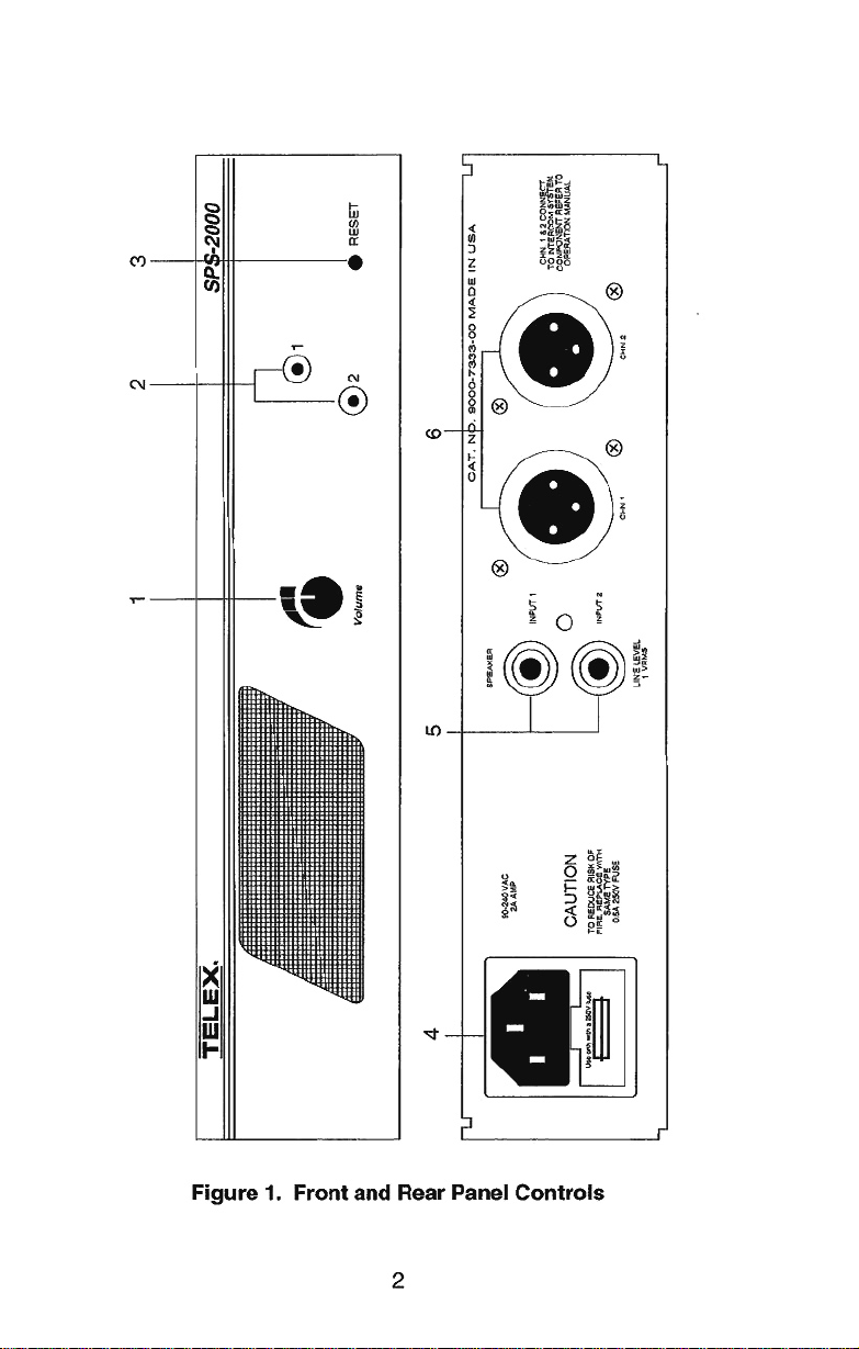
1.
Volume
Use this control to simultaneously adjust the speaker level for both
speaker input lines.
2.
Channel Power Status Indicators
The indicators are green for normal operation and change to red if their
is a short circuit or overload condition on a power output line. If an
indicator turns red, either disconnect the corresponding channel con-
nector or turn off the intercom System and locate the problem before
resuming operation.
3.
ßeset
The power status indicators will remain red after sensing a problem,
until power is removed from the SPS-2000 or reset is pressed. Press
ßesetafter the problem has been resolved or the appropriate channel
connector has been disconnected.
4.
AC Power lnlet
Connects the unit to an AC line and holds the line fuse.
The numbers refer to the callouts in Figure
Control
1.
Page 4

5.
SPEAKER
Input Jacks
These jacks can be connected to the SPEAKER outputs of a US-2000
or ES-4000 station. They may also be used to connect audio input from
some other
line-level program source (an auxiliary output from a radio
or tape player for example).
6.
CHN 1 and
CHN 2 lntercom Channel Connectors
These connectors carry power to intercom User stations and provide
channel termination for the audio signal.
INTERNAL SWITCHES AND JUMPERS
There are several internal switches and jumpers that affect operation.
These are described below. To gain access to the switches and jumpers,
remove one screw from the top
Switch and jumper locations are shown in Figure 2.
BalancedIUnbalanced Switch (S200)
Set this switch to the balanced (BAL) position to use the US-2000 with
Audiocom intercom channels. Set the switch to the unbalanced (UNBAL)
position for use with a Clear-ComB intercom System. (The factory default
setting is the balanced position for use with Audiocom.)
Jumpers
Cover and two screws on each side.
1.
Table
JUMPER
NUMBER
W101, W201,
W301, W401
*
Only one set of jumpers (either W102 through W402, or W101 through
Jumper Functions and Settings
JUMPER FUNCTION
Audiocom Termination Select*
1 &2
Pins
Pins
RTS Termination Select*
Pins
Pins
shorted: Audiocom line termination
2&3
shorted: No Audiocom line termination
1 &2
shorted: RTS line termination
2&3
shorted: No RTS line termination
DEFAULT
SETTING
Pins
shorted
Pins
shorted
W401) should be in the "pins 2&3 shorted" position at any time.
1&2
2&3
Page 5

Figure 2. Interna1 Switches and Jumpers
Page 6
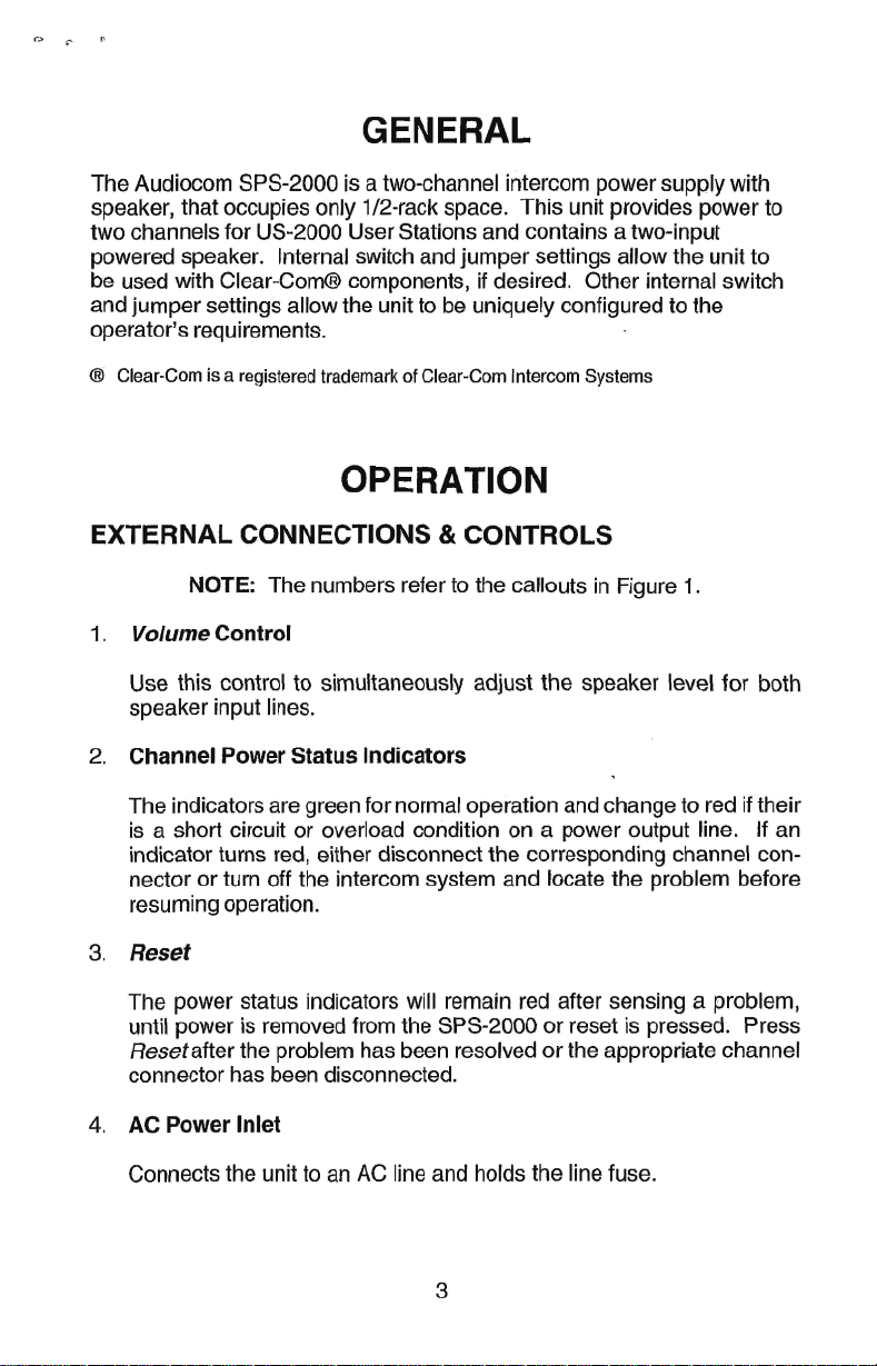
CONNECTOR PIN CONFIGURATIONS
Speaker Inputs
Type: RCA Phone Jack
Tip: Speaker output high
Sleeve: Common
lntercom Channel Connectors
Type: XLR-3M
Audiocom Mode (Internal switch S200 set to BAL position)
Pin
1
Common
Pin 2 +24 VDC output and audio termination
Pin 3 +24 VDC output and audio termination
Clear-Com Mode (Internal switch S200 set to UNBAL position)
1
Pin
Pin 2 +24 VDC output and audio termination
Pin 3 Audio termination
Common
Page 7

SPECIFICATIONS
GENERAL
Output Voltage:
24 f1 VDC
Output Current:
f
2A at 21
Output Impedance:
150R
300R f1 0%, balanced
Input Power Requirements:
92 to 255 VAC, 50 to 400 Hz
Environmental Requirements:
0°C to 50°C; 0% to 95% humidity, non-condensing
Dimensions:
1.75" (44.5 mm)
Weight:
2.5 pounds (1.1 3 kg)
SPEAKER AMPLlFlER
1 VDC
f5%, unbalanced
H
X
8.25" (209.5 mm) W X 10.25" (260.4 mm)
D
Frequency Response:
100 Hz to 20 kHz +I/-4 dB, at 0 dB output
Maximum Voltage Gain:
18 +3/-2 dB
Speaker lmpedance:
8Q
nominal
Input Level:
1.0 Vrms
Output Amplifier Power:
4W maximum into 8R
Output Voltage Level:
16 f1 Vp-P, before clipping
Page 8

FACTORY SERVICE
All equipment returned for repair must be accompanied by documenta-
tion stating your return address, telephone number and proof of date of
purchase, along with a description of the problem. In lieu of this, you
may obtain a Return Authorization form from our Customer Service
Department.
Customer Service Department
Telex Communications, Inc.
9600 Aldrich Avenue South
Minneapolis, Minnesota 55420 U.S.A.
Telephone: (61 2) 884-4051
(Collect calls not accepted)
Return equipment to:
Service Department
Telex Communications, Inc.
101 Minnesota Avenue
LeSueur, Minnesota 56058 U.S.A.
-
Warranty Repairs
Equipment being returned for warranty repair must be sent prepaid and
will be returned prepaid.
Non-Warranty Repairs
sent prepaid to Telex. If requested, an estimate of repair costs will be issued prior to service. Once your approval for repair, and repair of equip-
ment is completed, the equipment will be returned on a collect basis.
Collect charges may be avoided by sending a signed check for payment
in
full along with your signed estimate approval form (the estimate in-
cludes the shipping charge).
If in warranty, no charge will be made for the repairs.
-
Equipment that is not under warranty must be
 Loading...