

Page 1
INSTALLATION & OPERATION
INSTRUCTIONS
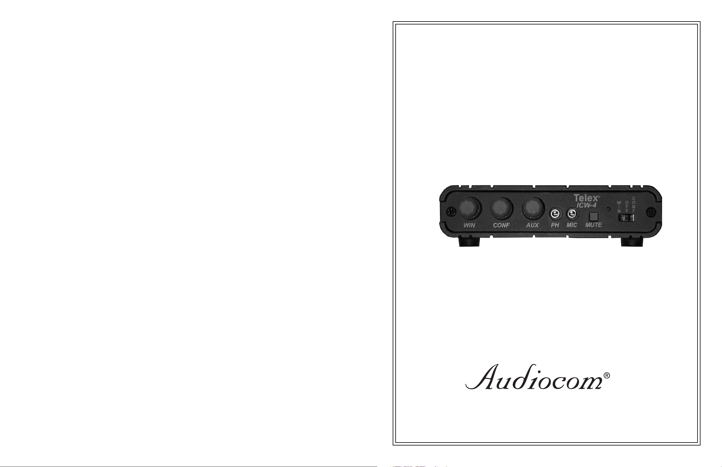
ICW-4 INTERCOM
9350-7687-000, Rev. A 3/2001
Page 2
UNPACKING & INSPECTION
Unpack the equipment from the shipping case and inspect for missing or damaged components. You should have all of
the following items:
1. ICW-4
2. RJ-45 to RJ45 Interconnect Cable
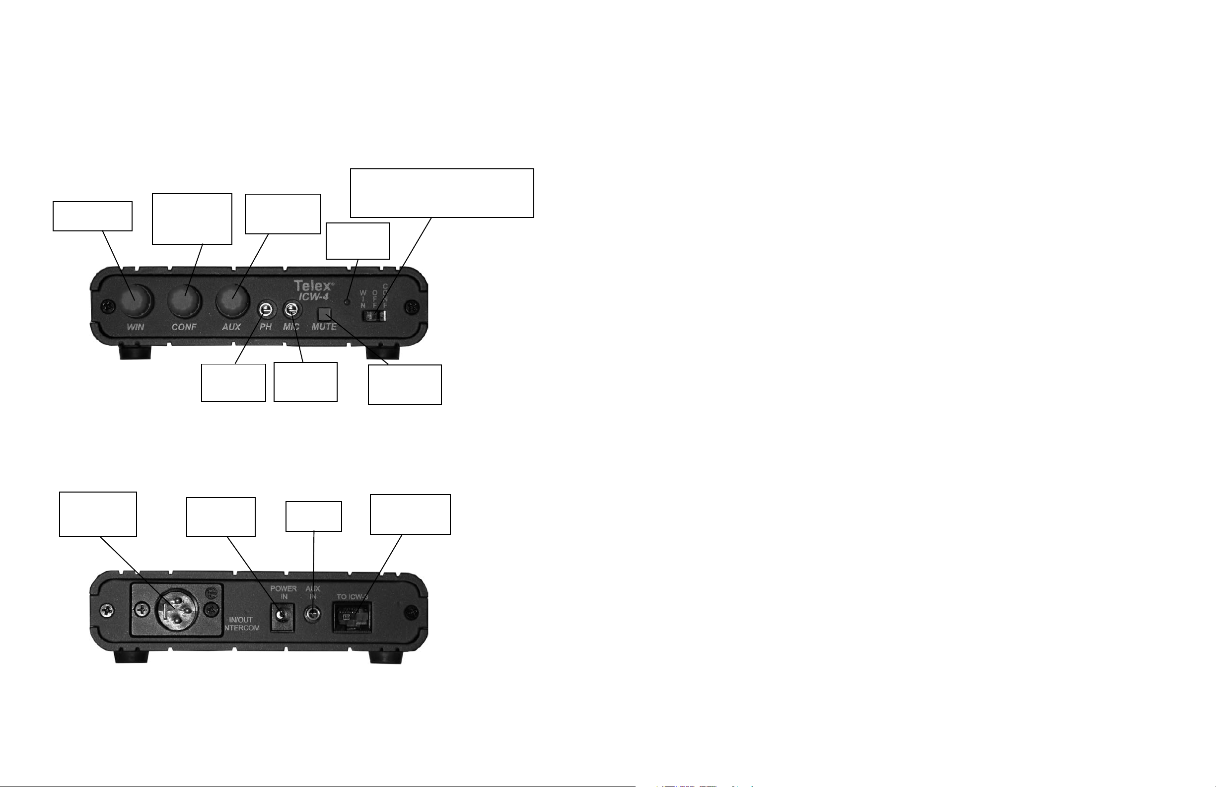
FRONT PANEL FEATURES
Selects which intercom the user is using.
WIN = ICW3
OFF = None
CONF = Main Intercom System
Volume control for
audio from ICW-3.
Volume control for
audio from
external intercom
system.
Volume control
for audio from
auxilliary source.
Illuminates red
when mute is
active.
NOTES:
REAR PANEL FEATURES
Input/Output to
external intercom
system.
Output to
headphone or
headset.
DC power input
from external
supply.
Input from
microphone or
headset
Auxilliary
audio input.
Mutes audio to
customer when
pushed in.
Power and audio
in/out connections
to/from ICW-3
Page 3

TRADEMARKS
Audiocom
tion purposes only and may be trademarks and/or registered trademarks of their respective companies.
WARRANTY INFORMATION
Products are warranted by Telex Communications, Inc. to be free from defects in materials and workmanship for a period of one
year from the date of sale.
The sole obligation of Telex during the warranty period is to provide, without charge, parts and labor necessary to remedy covered
defects appearing in products returned prepaid to Telex. This warranty does not cover any defect, malfunction or failure caused
beyond the control of Telex, including unreasonable or negligent operation, abuse, accident, failure to follow instructions in the
manual, defective or improper associated equipment, attempts at modification and repair not authorized by Telex, and shipping
damage. Products with their serial numbers removed or effaced are not covered by this warranty.
To obtain warranty service, follow the procedures entitled “Procedure for Returns” and “ Shipping to Manufacturer for Repair or
Adjustment”.
This warranty is the sole and exclusive express warranty given with respect to Audiocom products. It is the responsibility of the
user to determine before purchase that this product is suitable for the user’s intended purpose.
ANY AND ALL IMPLIED WARRANTIES, INCLUDING THE IMPLIED WARRANTY OF MERCHANTABILITY ARE LIMITED TO THE
DURATION OF THIS EXPRESS LIMITED WARRANTY.
NEITHER TELEX NOR THE DEALER WHO SELLS TELEX PRODUCTS IS LIABLE FOR INCIDENTAL OR CONSEQUENTIAL
DAMAGES OF ANY KIND.
CUSTOMER SUPPORT
Technical questions should be directed to:
®
is a registered trademark of Telex Communications. Names of other products mentioned herein are used for identifica-
SETUP
Audiocom® Mode
RTS™ TW™ Channel 2
or
ClearCom™ Mode RTS™ TW™ Channel 1 Mode
Customer Service Department
Te l ex
12000 Portland Avenue South
Burnsville, MN 55337 U.S.A
Telephone: (952) 884-4051
Fax: (952) 884-0043
RETURN SHIPPING INSTRUCTIONS
Procedure for Returns
If a return is necessary, contact the dealer where this unit was purchased.
If a return through the dealer is not possible, obtain a RETURN AUTHORIZATION from:
Customer Service Department
Telex Communications, Inc.
Telephone: 1-800-392-3497 or (952) 884-4051
Fax: 1-800-323-0498 or (952) 884-0043
DO NOT RETURN ANY EQUIPMENT DIRECTLY TO THE FACTORY WITHOUT FIRST OBTAINING A RETURN AUTHORIZATION.
Be prepared to provide the company name, address, phone number, a person to contact regarding the return, purchase order
number, the type and quantity of equipment, a description of the problem and the serial number(s).
Shipping to Manufacturer for Repair or Adjustment
All shipments of products should be made via United Parcel Service or the best available shipper prepaid. The equipment should
be shipped in the original packing carton; if that is not available, use any suitable container that is rigid and of adequate size. If a
substitute container is used, the equipment should be wrapped in paper and surrounded with at least four inches of excelsior or
similar shock-absorbing material. All returns must include the return authorization number. Units sent for repair or adjustment DO
NOT need a return authorization number
Factory Service department
Telex Communications, Inc.
West 1st Street
Blue Earth, MN 56013 U.S.A.
Determine which type of main intercom system you have. The ICW-4 supports connections to RTS™ TW™ chan-
1.
nels 1 or 2, ClearCom™, and Audiocom® systems.
To configure the ICW-4 for a given main intercom system, do the following:
2.
1. Remove the two screws holding the rear cover on the ICW-4 and carefully remove the cover.
2. Locate the mode select switch. It is located on the left side of the PC board as viewed with the rear cover off.
3. Set the switch for the appropriate mode. (See Figure Above)
There are three positions:
LEFT = RTS™ TW™ Ch 1
CENTER = RTS™ TW™ Ch 2 or ClearCom™
RIGHT = Audiocom®.
4. Carefully place the rear cover back on the unit being sure that the wiring harness is not pinched.
5. Insert and secure the two screws to hold the cover on.
Note: The following instructions assumes that the ICW-3 is mounted, but not connected to any wiring or microphones. See the connection diagrams on the next page for a pictorial view of these instructions.
Insert one end of the RJ-45 to RJ-45 link cable into the connector on the bottom of the ICW-3 and insert the other
3.
end into the connector on the rear of the ICW-4.
Insert the barrel connector of the switching power supply (the one included with the ICW-3) into the power jack on
4.
the rear of the ICW-4.
Insert the IEC line cord into the connector on the power supply.
5.
Wire a cable for interconnection to the main intercom system and insert it into the XLR connector located on the
6.
rear of the ICW-4. (See the SPECIFICATIONS section for the correct pinout for your particular Intercom system.)
Upon completion of any repair the equipment will be returned via United Parcel Service or specified shipper collect.
SETUP PROCEDURE CONTINUED ON NEXT PAGE
Page 4

(Optional) Insert the auxiliary audio feed into the AUX IN jack. See the specifications section for connector wiring
7.
information.
Connect the headset or headphone and microphone to the unit.
8.
Set the slide switch (intercom select) on the right front of the ICW-4 to the WIN position.
9.
While talking at a normal level, have an assitant monitor the ICW-3’s audio output on the customer side while you
10.
adjust the Outside Volume control on the ICW-3 until it is at an acceptable level for the assistant.
Have an assistant talk at a normal level and adjust the WIN Volume control on the ICW-4 until it is at an acceptable
11.
level in the headset or headphones.
Set the slide switch (intercom select) on the right front of the ICW-4 to the CONF position.
12.
While talking at a normal level, have an assistant make appropriate adjustments to the receive audio levels for the
13.
main intercom system.
Have an assistant talk at a normal level over the main intercom system and adjust the CONF Volume control for an
14.
acceptable level in the headset/headphone.
(Optional) Set the slide switch (intercom select) on the right front of the ICW-4 to the OFF position.
15.
(Optional) Place program material of a typical level on the Auxiliary audio feed and adjust the AUX Volume control
16.
for an acceptable level in the headset/headphone.
®
Telex
Mic
VolInside
ICW-3
Vol Outside
Mute
Vox
Phone Mic
Headset
OPERATION
To talk to customers through the ICW-3 intercom, set the slide switch located on the right front of the ICW-4 to the WIN
position. You can use the Mute switch on the front of the ICW-3 or ICW-4 to temporarily mute the audio that the customer hears.
To talk to others on the main intercom system, set the slide switch located on the right front of the ICW-4 to the CONF
position.
To prevent placing audio on either the ICW-3 or main intercom system, set the slide switch located on the right front of
the ICW-4 to the OFF position.
At all times, and regardless of the slide switch position, you will be able to hear the auxiliary audio feed (if present).
SPECIFICATIONS
Overall
Power Requirement: 12 to 15 VDC, 200 mA nominal (powers ICW-3 as well)
System Frequency Response: 200 to 4.5 kHz ±3 dB
Environmental: 0 to 55°C, 0 to 90% Humidity, non-condensing
Physical: 1.44” (36 mm)H x 5.27” (134 mm)W x 4” (102 mm)D; 0.88 lbs (0.4 kg)
Outputs
Headphone: Headphone impedance: 25 ohms, 31 mW, 109 dB peak SPL,
Voice range: 84 to 109 dB SPL
Headphone impedance: 150 ohms, 15 mW, 106 dB peak SPL,
Voice range: 81 to 1096 dB SPL
ICW-4
rear view
ICW-4
front view
To Intercom
System
CONF
WIN
Input/Output
House Intercom: Printed circuit board switch to select:
1) RTS™ TW™, channels 1 or 2
2) AudioCom® (balanced)
3) Clear-Com™ (unbalanced, single channel)
System levels range from -10 dBu to 0 dBu into 200 to 300 ohms. Unit uses a
INTERCOM
POWER
AUX
TOICW-3
IN
IN
IN/OUT
bilateral current source.
Input
Headset Microphone: Dynamic or Electret range: 2 to 15 mv @ 1 kHz typical into 1000 ohms.
POWER SUPPLY
FROM ICW-3
Source impedance dyanmic: 200 ohms. Source impedance electret: 1000 ohms.
Rear Panel
RJ45: Interconnects to ICW-3
Phone Jack: Minature 3.5 mm connection for Aux. In. Balanced 0 dB line level input.
Tip, Audio +; Ring, Audio -; Sleeve, N.C.
Power Connector: DC power input, 12 to 15 volts, 150 to 200 mA. Jack: 2.5 mm, center positive.
®
C
Telex
O
O
W
ICW4
N
F
I
F
F
N
MUTE
MIC
PH
AUX
Intercom Connector: Connects to House Intercom line.
RTS™ TW™: Pin 1, common; Pin 2, Channel one; Pin 3, Channel two
Clear-Com™: Pin 1, common; Pin 2, power; Pin 3, audio
AudioCom®: Pin 1, common; Pins 2, 3 balanced audio, phantom power
 Loading...