

Page 1
GENERAL
The IC-S is a single-channel speaker station
designed for use with an external microphone.
There are four versions of the IC-S; all identified
by the same model name, but distinguished from
one another by certain features. For purposes of
documentation, the four versions will be
designated according to features as follows:
IC-SF: Wall-mounted station without light
1.
signal (no indicator light on front panel).
DESCRIPTION
output Impedance:
Phones: 60 ohms (Designed for use with
150-600 ohm phones.)
Output Power:
Phones: 75 milliwatts into 150 ohms.
Speaker: 2 watts into 8 ohms.
Line: 10 milliwatts ($10 dBM).
Speaker Acoustic Output:
100 dB SPL at 1 meter on axis at full power.
IC-S: An IC-SF mounted in a carrying case
2.
with rear panel audio connectors.
IC-SF/LS: Wall-mounted station with light
3.
signal (has indicator light on front panel).
IC-S/LS: An IC-SF/LS mounted in a
4.
carrying case with rear panel audio
connectors.
/
I
\-/
SPECIFICATIONS
Frequency Response:
Transmit: 150-7,000
Receive: 180-6,000
200-5,000 Hz usable for speaker.
Equivalent lnput Noise:
Mic Input: 2 microvolts (-1 16 dBV)
150-7.000
HZ.
Hz +1, -3 dB.
Hz +1, -3 dB for phones.
Total Harmonic Distortion:
Mic to line: 1% at 10 milliwatts.
Line to phones: 1% at 75 milliwatts.
Common Mode Rejection:
Line: 40 dB at 60 Hz.
Voltage Gain:
Mic to line: 200 (46 dB).
Line to phones: 24 (28 dB) adjustable to zero.
Speaker Attenuation:
With mic only connected: 0 dB.
With headset connected (mic
With -10 switch: 10 d~ (non-LS units only).
With headset and -10 switch: 16 dB (non-LS
units only).
Power Requirements:
Voltage: 24 Vdc nominal. Will operate on
12-30 Vdc.
Current: No signal
Average talk
Signalling (LS units only)
- 25 milliarnps.
-
60 milliamps.
+
phones): 6 dB.
- 60 milliamps.
lnput Level:
Mic: 5 millivolts nominal, 12 millivolts
maximum.
Line: 1 volt (0 dBM) nominal, 4 volts (12 dBM)
maximum.
Input Impedance:
Mic: Greater than 5,000 ohms. (Designed for
use with 50-600 ohm microphones).
Line: Greater than 10,000 ohms. Transformer
coupled.
/'
.
Dimensions (connectors not included):
IC-S, IC-S/LS: 10.25 inches (260.35 mm) wide
x 7.7 inches (195.6 mm) high x 3.75 inches
(95.25 mm) deep.
IC-SF, IC-SF/LS: 9 inches (228.6 mm) wide x
7 inches (177.8 mm) high
(69.85 mm) deep behind front panel. If unit is
installed using screw-clamp terminals, wire
wrap pin may be cut off; depth reduces to
2.38 inches (60.45 mm).
x
2.75 inches
Page 2
Connectors:
IC-S, IC-SILS: Miclheadset - one XLR-4M.
-
one XLR-3M and one XLR-3F wired in
Line
parallel.
IC-SF, IC-SFILS: Miclheadset
-
three combination screw-clamp, wire-
Line
wrap terminals (screw-clamps will accept No.
22
-
No.
14
AWG stranded or solid wire).
External power -three combination screw-
clamp, wire-wrap terminals (use optional).
-
one XLR-4M.
3.
Remove the jumper between the +24 and
terminals.
4.
Connect the
+24 terminal.
5.
Connect the
COM terminal.
When all connections are completed, mount unit
in electrical box using the four screws supplied.
"+"
lead of the supply to the
"-"
lead of the supply to the
PH
INSTALLATION
IC-S and IC-SILS
These stations may be connected to the intercom
line using prefabricated cables with XLR-3 end
connectors, or cables may be made to lengths as
required and terminated with XLR-3 cable
connectors.
IC-SF and IC-SFILS
When powering from the intercom line:
Refer to the label on the rear cover
1.
Connect the two intercom line wires to the
2.
LlNE terminals.
3. Connect the dc return wire to the SHLD
terminal.
Connect a jumper between the 4-24 and
4.
terminals (disregard this step with factory-
-
fresh units
place).
When powering from
Refer to the label on the rear cover.
1.
Connect the two intercom line wires to the
2.
LlNE terminals.
jumper should already be in
a
separate dc supply:
PH
OPERATION
SpeakerlHeadphone VOLUME Control:
listen level only. Does not affect mic level.
SPEAKER Switch (IC-S, IC-SF):
position switch. In the ON position, the speaker
has normal volume output. In the
speaker output is reduced. In the OFF position,
there is no speaker output. The
positions do not affect the headphone or
microphone levels.
SPEAKER ONIOFF and CALL Switch (IC-SILS,
IC-SFILS):
ON and OFF positions turn the speaker on and
off but do not affect the headphone output or
microphone level when using a headset. The
CALL position is used for light signalling. In the
CALL position, with the switch held continuously,
an inaudible signal is sent to all other stations on
the line. On those stations with light signalling
the Call Indicator lights will illuminate. When
another station responds verbally, release the
switch and it will automatically return to the ON
position for two-way voice communication.
MicIHeadset Connector:
microphone or a headset with dynamic
microphone and headphones.
Call Indicator Light (IC-SILS, IC-SFILS):
Provides a visual indication when the station is
being called.
This is a three-position switch. The
Accepts a push-to-talk
This is a three-
-10
-
10
Adjusts
dB position,
dB and OFF
Page 3
11
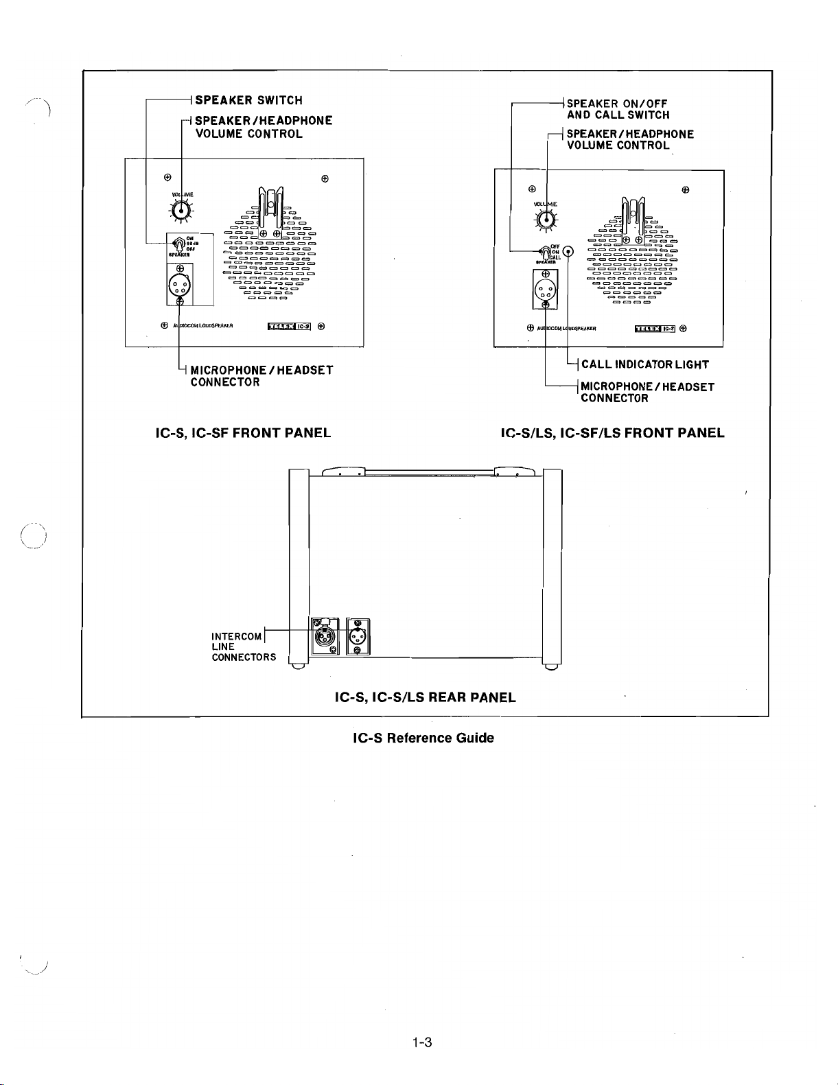
SPEAKER SWITCH
SPEAKER/HEADPHONE
VOLUME CONTROL
1
MICROPHONEIHEADSET
CONNECTOR
I
SPEAKER ON/OFF
AND CALL SWITCH
SPEAKER/HEADPHONE
VOLUME CONTROL
r'
I
4CALL INDICATOR LIGHT
[----I
MICROPHONE/ HEADSET
CONNECTOR
IC-S, IC-SF FRONT PANEL
IC-SILS, IC-SFILS FRONT PANEL
IC-S, IC-SILS REAR PANEL
IC-S Reference Guide
Page 4

MAINTENANCE
IC-S Mechanical Exploded View
1-4
Page 5

IC-S Mechanical Parts List
All parts used on all versions unless otherwise specified
*
ITEM NO.
1
2
3
4
5
6
7
8
9
10
11
12
13
14
15
16
17
18
19
20
2 1
22
23
24
25
26
27
28
29
30
3 1
32
33
34
35
36
37
38
39
40
DESCRIPTION
Cover, End (IC-S, IC-S/LS)
3/4
Screw, 6-32 x
(IC-S, IC-S/LS)
Nut, Hex, No. 6
Washer, Lock, No. 6
Speaker, 5-Inch, 8-Ohm
Chassis
Washer, Lock
Nut, Hex
Panel, Front
Screw, 6-32 x 1 (IC-S, IC-S/LS)
Microphone Hanger
Washer, Lock
Screw, 8-32 x
!4
Knob
Screw, 4-40 x
3/s
Connector, XLR-4M (J2)
Switch, Toggle, DPDT (IC-S, IC-SF)
Switch, Toggle, SPDT (IC-S/LS, IC-SF/LS)
%W,
Potentiometer, 100K,
+20°/0 (R22)
Connector, 14-Position (J1)
Terminal (For item 19)
PCB Assembly, Audio
Spacer
Cover, Rear
Washer, Lock
Screw, 4-40
x
%
Foot, Self-Adhesive (IC-S, IC-S/LS)
Housing (IC-S, IC-S/LS)
Connector, XLR-3M (J4
Screw, (J3
-
IC-S, IC-S/LS)
-
IC-S, IC-S/LS)
Connector, XLR-3F (IC-S, IC-S/LS)
Bezel (IC-S, IC-SF)
Nut, Hex, No. 4 (IC-S/LS, IC-SF/LS)
Angle Bracket
!4
Screw, 4-40 x
(IC-S/LS, IC-SF/LS)
LED (IC-S/LS, IC-SF/LS) (DS1)
Clip, LED Mtg. (IC-S/LS, IC-SF/LS)
PCB Assy, 20 kHz Light Signal (IC-S/LS, IC-SF/LS)
Connector (IC-S/LS, IC-SF/LS)
Terminal (For item 37)
Collet
Cap
.
Lens, LED (IC-S/LS, IC-SF/LS)
PART NO.
9291 3-000
54993-097
521 88-008
5001 4-001
57823-000
92906-000
5001 4-004
50033-001
92904-000
51 845-098
63356-001
5001 4-1 03
51 845-1 28
53432-1 1
51 847-1 12
50994-004
57483-000
57481-003
571 45-002
52264-01 4
54460-001
92902-001
57798-000
92908-000
5001 4-002
51 845-041
56471-000
92933-000
50994-000
51 847-01
50995-000
9521 9-000
521 88-006
9521 5-000
51 845-038
58683-000
53627-002
96080-000
52264-006
54460-001
53434-1 01
53433-1 15
59739-000
6
1
92909. Rev
92910. Rev
92931, Rev
92921, Rev
92930. Rev
AC
J
G
H,
C
*
IC-S: Portable station, no light signal.
IC-SF: Flush-mount station, no light signal.
IC-S/LS: Portable station, light signal.
IC-SF/LS: Flush-mount station, light signal.
Page 6

Page 7

IC-S
Audio
PCB Assembly Parts
All parts used in all versions.
Capacitors are in microfarads unless otherwise specified.
Resistors are in ohms, carbon,
%W,
+5% unless otherwise specified.
List
REFERENCE NO.
C1
C2,21,26
C5,16
C6,9,27
C7
C8,14
C11
C12
C13,24
C15
C17
C18
C22
C23
C25,28
CR1
P 1
Q1
R1
R 2
R3,4,5,7,14
R6,8
R9
R10
R11,12,15,16
'
R13,20
R17
R18,19
R21,R28
R23
R24
R25,26
R27
T 1
U 1
U 2
U 3
DESCRIPTION
Capacitor, 1,
35V, Tantalum
Capacitor, 0.01, 1OOV
Capacitor, 10, 25V, Electrolytic
Capacitor, 0.1
Capacitor, 47
pF, 100V
Capacitor, 100 pF, 100V
Capacitor, 47, 35V, Electrolytic
Capacitor,
.l,
50V, Ceramic
Capacitor, 0.001
Capacitor, 220 pF
Capacitor, 10, 1 OV, Electrolytic
Capacitor, 220, 35V
Capacitor, 1, 50V
Capacitor, 100, 35V, Electrolytic
Capacitor, 4.7, 25V, Electrolytic
Diode, 1 N4003
Pin Assembly
Transistor, 2N2925
Resistor, 470
Resistor, 390
Resistor, 68K
Resistor, 150K
Resistor, 330
Resistor,
2.7K
Resistor, 1 Meg
Resistor, 47K
Resistor,
1.8K
Resistor, 1 OOK
Resistor, 15K
Resistor, 22K
Resistor, 22
Resistor, 1 K
Resistor, 180
Transformer
IC, Low Noise Preamplifier, AN360
IC, Dual Low Noise Op Amp,
NE5532
IC, Amplifier, Audio Power, ULN2280B
Terminal Block
PART NO.
52257-049
521 57-251
51 821-020
52708-024
521 57-004
521 57-008
51821-010
52676-1 13
521 57-022
521 57-01 2
51 821-045
521 60-092
51821-106
51821-01 1
51 821-079
50745-002
52263-01 4
51 547-000
521 54-289
521 54-291
521 54-237
521 54-229
521 54-293
521 54-271
521 54-209
521 54-241
521 54-275
521 54-233
521 54-253
521 54-249
521 54-321
521 54-281
521 54-299
52444-001
53270-000
53295-000
53236-000
57703-000
92902,
Rev
Y
Page 8

IC-S
20
KHz
Light Signal PCB Assembly Parts List
All resistors in ohms,
%W,
+5% unless otherwise noted.
All capacitors in microfarads unless otherwise noted.
REFERENCE NO.
C1,2,3
C4
C5,7,9
C6
C8
C10
C11
CRI
J5
Q1,3
Q2
R 1
R2,5
R3,15
R 4
R 6
R 7
R 8
R11
R12
R14
U
1
VRI
DESCRIPTION
Capacitor, Ceramic, 0.001, 50V,
+lOO/o
Capacitor, Ceramic, 100 pF, 500V, +1O0/0
Capacitor, Tantalum, 0.1, 35V, +20°/0
Capacitor NPO, Ceramic, 0.0022, 50V, +2%
Capacitor, Electrolytic, 4.7, 25V, +20°/0
Capacitor, Electrolytic, 10, 25V, +20°/o
f
Capacitor, Ceramic, 0.047, 25V,
80 -20%
Diode, 1 N4148
Connector, 7-Position
Transistor, 2N2925
Transistor, J175
Resistor, 2.2M
Resistor, 1 M
Resistor, 20K
Resistor, 10K
Resistor, 62K
Resistor, 10K
Resistor, 47K
%W,
%WI
k2%
%W,
+5%
+1O0/0
Resistor, 24K,
Resistor, Variable, 5K,
Resistor, 1.2K,
IC, Tone Decoder, XR567
%W,
Diode, Zener, 6.2V,
+5%
Socket, &Pin
PART NO.
52676-1 01
521 57-008
52257-065
35694-034
52723-01 3
52723-01 4
521 58-033
52228-000
57721 -007
51 547-000
54687-001
521 54-201
521 54-209
521 54-250
521 54-257
521 54-238
521 54-257
521 54-241
521 55-248
148-048
57
521 54-456
53258-000
51 302-01 7
53041 -002
Page 9

JUMPER~PH"
FEMOVE JUMPER AND CONNECT P4VDC TO
COM. FOR SEPARATELY POWERED OPERATION.
NOTES:
1.
ALL RESISTORS IN OHMS,
1/4
WATT,
25%
OTHERWISE NOTED.
2.
ALL CAPACITORS IN MICROFARADS UNLESS
OTHERWISE NOTED.
3.
-)--
-
4.
ALL VOLTAGES ARE DC MEASURED USING A HIGH
INDICATES RECEIVE SIGNAL PATH.
INDICATES TRANSMIT SIGNAL PATH.
IMPEDANCE METER UNDER NO-SIGNAL
CONDITIONS WlTH CHASSIS AS REFERENCE.
5.
WHERE TWO VOLTAGES ARE INDICATED, THE FIRST
IS WlTH A HEADSET CONNECTED AT J2 AND THE
SECOND IS WITHOUT.
6.
THIS SCHEMATIC SUBJECT TO CHANGE
ACCOMMODATE DESIGN IMPROVEMENTS.
UNLESS
.
TO
R:,5
TO LIGHT SIGNAL PCB
SPEAKER AMPLIRER
I
1
U2
I
(
IC-S/LS. IC-SWLS ONLY)
---
Page 10

96078,
Rev
IC-S
20
KHz
J
Light Signal Schematic Diagram
1-10
 Loading...