

Page 1
r
a
Telex
User Instructions
AUDIOCOM@
MODEL IC-4M
MASTER STATION
TELEX.
TELEX COMMUNICATIONS, INC. 9600 Aldrich Ave.
381 09-31
5
Rev
A
So.,
Minneapolis, MN 55420 U.S.A.
June
1991
Page 2
GENERAL INFORMATION
GENERAL DESCRIPTION
The Telex Audiocom'" Model IC-4M is a fourchannel master intercom station designed for
balanced-line operation. It features light
signaling, stage announce (public address)
output, auxiliary program input, and IFB
operation. It is also compatible with the Telex
Model IC-4SX System Expander.
The IC-4M is equipped with an internal power
supply capable of powering up to 150 remote
stations. It is rack-mountable in single or dual
configurations.
OPERATING FEATURES
FRONT PANEL
The front panel has a 4-pin XLR connector for a
dynamic-microphone headset. A 3-pin connector
is also provided for a condenser-type gooseneck
microphone which can be used with an external
speaker connected at the rear panel. Separate
volume controls are provided for headset and
speaker. A three-position rocker switch is used
for microphone
signaling. A momentary-type stage announce
push-button switch allows the station operator to
page or make public address announcements
through an exernal PA system.
on/off switching and for call light
volume control adjusts the auxiliary input level. A
3-pin XLR receptacle connector provides a
balanced, transformer-coupled stage announce
output. A 9-pin D-type connector provides
system buss connection for an IC-4SX System
Expander.
The IC-4M has an integral power cord for ac
operation, and the main power fuse is accessible
on the rear panel.
SPECIFICATIONS
Interface Requirements:
-
Dynamic Headset: 50-600 ohm microphone;
150-600 ohm headphones
-
Condenser Microphone: 6.8K ohm, -55 dB
sensitivity (typical)
-Speaker:
-Auxiliary Program Source: 100 mV-10 Vrms
-
Channel Level: 1 Vrms (0 dB) nominal
-
Impedance: Supplies 300 ohms termination to
channel
Power Supply:
-
Output Voltage: 25V regulated
-Output Current: 500
per channel; 2 amp maximum continuous total
Power Requirements:
maximum (may be modified for 220V or 240V
operation)
&ohm, 5W
mA maximum continuous
120V, 50-60 Hz, 90W
Channel select
momentary-type push-button IFB switches, and
call indicator lights are provided for each
channel. The channel-select switches indicate
the "on" state by displaying a color bar. A
type power off/on switch is provided along with
an LED to indicate "power on".
REAR PANEL
A
1M-inch (6.35 mm) phone receptacle
connector accepts an external speaker (8 ohms
minimum). A 3-pin XLR connector and a
receptacle connector for each intercom channel
permit loop-through connection of intercom
channels.
A 3-pin XLR receptacle connector accepts either
balanced or unbalanced, line-level auxiliary
program input. A rotary switch assigns the
auxiliary program to one or all intercom channels
and also has an "off" position. An auxiliary
on/off push-button switches,
rocker-
Headphone Amplifier:
-
Maximum Output: 12V p-p into 150 ohms (120
mW); 21V p-p into 600 ohms (90 mW)
-Frequency Response (Channel to Phones): 200
Hz-7 kHz
-
Voltage Gain (Channel to Phones): Adjustable
from 0-26 dB
-
Sidetone: Adjustable from 25 dB null to full-on
Speaker Amplifier:
-
Maximum Output: 3W into 8 ohms at 1% THD
-
Voltage Gain (Channel to Speaker): Adjustable
from 0-34 dB
Auxiliary Amplifier:
-
Input Impedance: 50K ohms balanced; 25K
ohms unbalanced
-
Frequency Response (Auxiliary to Channel):
150 HZ-10
-Voltage Gain (Auxiliary to Channel):
Adjustable from
onset of AGC limiting)
-
Common Mode Rejection: 40 dB
kHz
0-30 dB (measured before
Page 3
SPECIFICATIONS (CONT)
Connectors:
-
Headset Input: One XLR-4M
-
Condenser Mic: One 3-pin male
-
Auxiliary Input: One XLR-3F
-
Stage Announce (PA Output): One XLR-3F
-
Intercom Channels: One XLR-3M and one
XLR-SF wired in parallel for each channel
-
Speaker: One IN-inch (6.35 mm) phone jack
-Ac Power: One 6-foot (1.8 m) line cord with
3-pin U.S. grounding plug
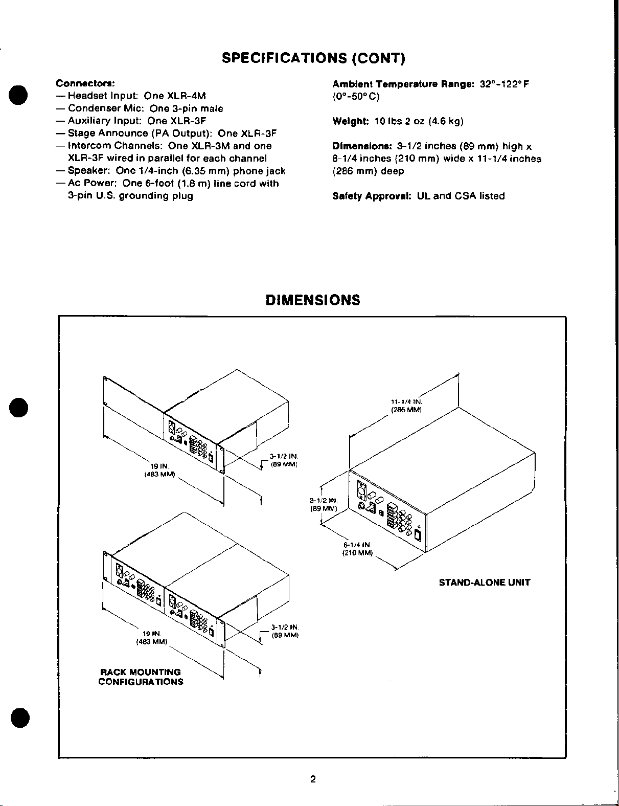
DIMENSIONS
Ambient Temperature Range:
(0"-50"
Weight:
Dimensions:
8-1/4 inches (210 mm) wide x 11-1/4 inches
(286 mm) deep
Safety Approval:
C)
10 Ibs 2 oz (4.6 kg)
3-1/2 inches (89 mm) high x
UL
and CSA listed
32"-122" F
3-
(8
STAND-ALONE UNIT
Page 4

STANDARD CONNECTOR USAGE
Connector Function
Monaural dynamic
headset or mic
Condenser microphone
External power
source
Single channel intercom
Connector Type
XLR-4 or
equivalent
0
XLR-4M XLR-4F
30
0
02
Standard Usage
-
Mic shield
1
-
Mic hot
2
3
-
Headphone hot
4
-
Headphone shield
1 - Bias/Audio
2 - Ground
-
No connection
3
Do not connect the mic shield
and headphone shield together.
0
Jones P-302-AB
or equivalent
ouivaleo
XLR-3 or
0
XLR-3M XLR-3F
Wide contact
Narrow contact
-
Dc return (Ground)
1
-
Intercom channel
2
-
lntercom channel
3
-
Negative
-
Positive
24 Vdc nominal
12 Vdc minimum
30 Vdc maximum
Either intercom channel wire
may be connected to either
connector contact
Comments
2
or 3.
Auxiliary input
Stage announce
System buss
XLR-3 or
equ~valent
(-J
0
XLR-3F
XLR-3 or
equivalent
0
0
XLR-3F
9-p~n
D connector
54321
00000
.i
9876
1
-
Ground
2
-
Balanced lnput
3 - Balanced input
1
-
Ground
2
-
Balanced output
-
Balanced output
3
1 - Ground
2
-
Ground
-
25 Vdc
3
4 - 25 Vdc
5 - Current sense
6
-
Channel
Channel B
Channel C
Channel
A
D
7
8
9
-
-
-
GROUND
(e*
Balanced plug wiring
0
Unbalanced plug wiring
c+
Balanced plug wiring
0
Unbalanced plug wiring
INPUT
INPUT
@
GROUND INPUT
GROUND
OUTPUT
OUTPUT
OUTPUT
GROUND OUTPUT
0
GROUND
GROUND
Page 5

REFERENCE
DYNAMIC HEADSET Connector
-
HEADSET VOLUME Control
-
SPEAKER Output VOLUME Control
GUIDE
-
Director CHANNEL SELECT Switches
-
CALL lndicator Lights
-HEADSET-
VOLUME
E
-MICA
R
SPEAKER
VOLUME
-
-
CALUMIC Switch
-
CONDENSER Mic Input
lspEAIR
out;ut
AUXILIARY CHANNEL SELECT Switch
CHA
JNEL
INTERRUPT
4
-
INTERRUPT (IFB) Switches
STAGE ANNOUNCE Button
POWER Switch
and
lndicator Light
POWER
4
+
4
IC-4M
[
Power Cord
AUXILIARY VOLUME Control
Auxiliary INPUT Connector
Intercom
CHANNEL
Connectors
STAGE ANNOUNCE Output
Main Fuse
SYSTEM BUSS Connector (To IC-4SX)
Page 6

OPERATION
SUPPLYING POWER
1.
Plug the power cord into a wall outlet.
2.
Turn the front panel main POWER switch on.
The yellow power indicator light above the
switch should illuminate.
USING THE AUXILIARY INPUT
1.
Plug the auxiliary program source into the
AUX INPUT connector.
2.
Assign the auxiliary program source to the
desired
CHANNEL SELECT rotary switch.
3. Adjust the AUXILIARY VOLUME control for a
comfortable listening level at intercom
stations on the selected
channel(s) with the AUXILIARY
channel(s).
USING THE CALL FEATURE
CALLING REMOTE STATIONS
Select the channel(s) to be called by setting
1.
the appropriate director CHANNEL SELECT
switch(es) to the "on" position.
Press and hold the CALL/MIC switch in the
2.
CALL position. The call indicator light for
each selected channel should illuminate.
20
Also, an inaudible
each selected channel to activate the call
indicator lights on any connected remote
stations.
3. When a station responds verbally, release the
call mic switch, and it will automatically
return to the ON position for normal two-way
communication.
RECEIVING CALL SIGNALS
When a remote station calls the IC-4M, the
appropriate call indicator light will illuminate. To
respond, set the appropriate director CHANNEL
SELECT switch to the "on" position, and then
proceed with normal two-way communication.
kHz signal is sent on
VOICE COMMUNICATION
To communicate with remote intercom stations
on one or more channels:
1.
Set the desired front panel director
CHANNEL SELECT push-button
to the "on" position.
2.
Set the CALL/MIC switch to the ON position.
(To listen only, set this switch to OFF.)
3a. If using a headset, plug the headset into the
DYNAMIC HEADSET connector, and adjust
the HEADSET VOLUME control for a
comfortable listening level. (See
Adjustment.)
3b. If using a condenser microphone together
with an external speaker, plug the
microphone into the CONDENSER
connector, plug the speaker into the rear
panel SPEAKER jack, and adjust the
SPEAKER VOLUME control for a comfortable
listening level.
switch(es)
Sidetone
USING THE INTERRUPT
(IFB) FEATURE
The INTERRUPT fold-back (IFB) switches are
used primarily for momentary-type
communications such as cueing on-the-air talent,
or for providing brief responses to received call
signals. During interrupt, the auxiliary program
source is disconnected from all channels, and the
director is connected to the interrupted channel.
To use this feature:
1.
Set the CALL/MIC switch to ON.
Press and hold the desired channel IFB
2.
button while communicating.
3.
Release the IFB button when finished to
restore the auxiliary program and break the
momentary communication link.
Page 7

OPERATION (CONT)
USING THE SIDETONE ADJUSTMENT
STAGE ANNOUNCE FEATURE
1. Connect the rear panel STAGE ANNOUNCE
output to the PA system.
2.
Set the CALL/MIC switch to ON.
3.
Press and hold the STAGE ANNOUNCE
button while speaking into the microphone.
Sidetone refers to that portion of the director's
own voice signal which is heard in the director's
headset. The amount of
each channel through small openings
cover (labeled
D). Adjustment may be made
blade screwdriver.
SIDETONE A through SIDETONE
sidetone is adjustable for
in the top
using a small, flat-
SERVICE INFORMATION
FACTORY SERVICE
All Audiocom equipment returns must be sent
prepaid. Telex will not accept collect shipments.
The following information must accompany all
equipment returned for repair:
IN-WARRANTY RETURNS:
1. Your name, address and telephone number.
2. Purchaser's name and address (if different
from above).
3.
Copy of proof of purchase (keep your original).
4. Model and serial numbers (or date codes).
5.
A complete description of the problem.
NON-WARRANTY RETURNS:
1. Your name, address and telephone number. Telex Communications, Inc.
2. Model and serial numbers (or date codes).
3.
A complete description of the problem.
All equipment repaired in-warranty by Telex will
be returned prepaid by Telex.
If requested, an estimate will be sent before
repairing non-warranty equipment. This is a
guaranteed estimate -final charges will not
exceed what is quoted. If payment is sent along
with your estimate approval, COD charges will be
avoided; otherwise, equipment will be returned to
you COD.
FACTORY SERVICE ADDRESS:
Service Department
Telex Communications, Inc.
1720 East 14th Street
Glencoe, Minnesota 55336 U.S.A.
CUSTOMER ASSISTANCE
Customer Service Department
9600 Aldrich Avenue South
Minneapolis, Minnesota 55420 U.S.A.
Telephone: (61 2) 884-4051
(Collect calls not accepted)
 Loading...