

Page 1
IC-I
AND
IC-I
F
GENERAL DESCRIPTION
The IC-1 and IC-1 F are single-channel, single-
line intercom stations designed for use with
dynamic headsets.
The IC-1 is a compact, lightweight unit which
may be worn on the user's belt, or mounted
permanently to other equipment. Parallel-wired
male and female XLR-3 connectors, mounted on
the rear panel, allow units to be daisy-chained
using prefabricated intercom cables.
F
The IC-1
designed for permanent installation in an
electrical pull box. The unit is connected to the
intercom system by means of combination wire-
wrap, screw clamp terminals.
Both the IC-1 and IC-1 F are available with and
without light signalling capability. The light
signal versions are distinguished by the presence
of a Call Indicator Light on the front panel. For
purposes of documentation, the light signal
versions will be designated the IC-1/LS (an IC-1
with light signalling, and the IC-1 F/LS (an IC-1 F
with light signalling).
Specifications apply to all versions unless
otherwise noted.
Frequency Response:
Transmit: 150-7,000
Receive: 180-6,000
is a flush-mount version of the IC-1
SPECIFICATIONS
Hz
t1, -3 dB.
Hz
+1,
-3
dB.
Output Impedance:
Phones: 60 ohms (Unit is designed for
use with 150-600 ohm phones.)
Output Power:
Phones: 75 milliwatts into 150 ohms.
Line: 10 milliwatts (+I0 dBM).
Total Harmonic Distortion:
Transmit: 1% at 10 dBM.
Receive: 1% at 75 milliwatts.
Common Mode Rejection:
Line: 40 dB at 60
Power Requirements:
Voltage: 24 Vdc nominal. Unit will
operate on 12-30 Vdc.
Current: No signal
12 milliamps (IC-1/LS, IC-1 F/LS).
Average talk
20 milliamps (IC-1/LS, IC-1 F/LS).
Signalling
Dimensions (without external connectors):
IC-1, IC-I/LS: 1.75 inches (44.45 mm) high
3.0 inches (76.2 mm) wide x 5.39 inches
(136.9 mm) long.
IC-IF, IC-1F/LS: 4.5 inches (114.3 mm) high x
4.62 inches (117.35 mm) wide x 2.5 inches
(63.5 mm) deep behind front panel. If unit is
installed using screw-clamp terminals, wire-
wrap pins may be cut off and depth reduces to
2.15 inches (54.61 mm).
-
Hz.
-
8
milliamps (IC-1, IC-IF),
-
12 milliamps (IC-1, IC-IF),
30 milliamps (IC-I/LS, IC-1 F/LS).
x
Equivalent lnput Noise:
Mic Input: 2 microvolts (-1 16 dBV)
150-7,000
Input Level:
Mic: 5 millivolts nominal, 12 millivolts
maximum.
Line: 1 volt (0 dBM) nominal, 4 volts (12 dBM)
maximum.
lnput Impedance:
Mic: Greater than 5,000 ohms. (Unit is
designed for use with 50-600 ohm phones).
Line: Greater than 10,000 ohms.
HZ.
Weight:
IC-1, IC-1/LS: 1.5 Ibs (0.51 kg)
Connectors:
IC-1/LS: One XLR-4M for headset
connection. One XLR-3M and one XLR-3F,
wired in parallel, for intercom line
connection.
IC-1 F, IC-1 F/LS: One XLR-4M for headset
connection. Three combination screw-clamp,
wire-wrap terminals for intercom line
connection. Screw-clamp terminals accept
No. 22 through No. 14 AWG stranded or solid
wire.
Page 2
INSTALLATION
IC-1 and IC-11LS
Permanent installation may be accomplished by
removing the belt clip and utilizing the threaded
belt clip mounting holes along with the additional
threaded hole in the case to secure the unit to
other equipment. These holes accept No. 6-32
machine screws. Screws may extend
3/16-inch
into unit. These units may also be rack mounted
using an RM-13 Rack Mounting Kit.
IC-1 F and IC-1 FILS
After running wires to the electrical box where
the unit will be located, refer to the label on the
rear cover of the unit and make connections as
indicated. It is not necessary to observe polarity
when connecting intercom line wires. Connect
the power supply dc return wire to the SHLD
terminal. If another set of wires is to be run from
this unit to another intercom station, connect
these wires at this time.
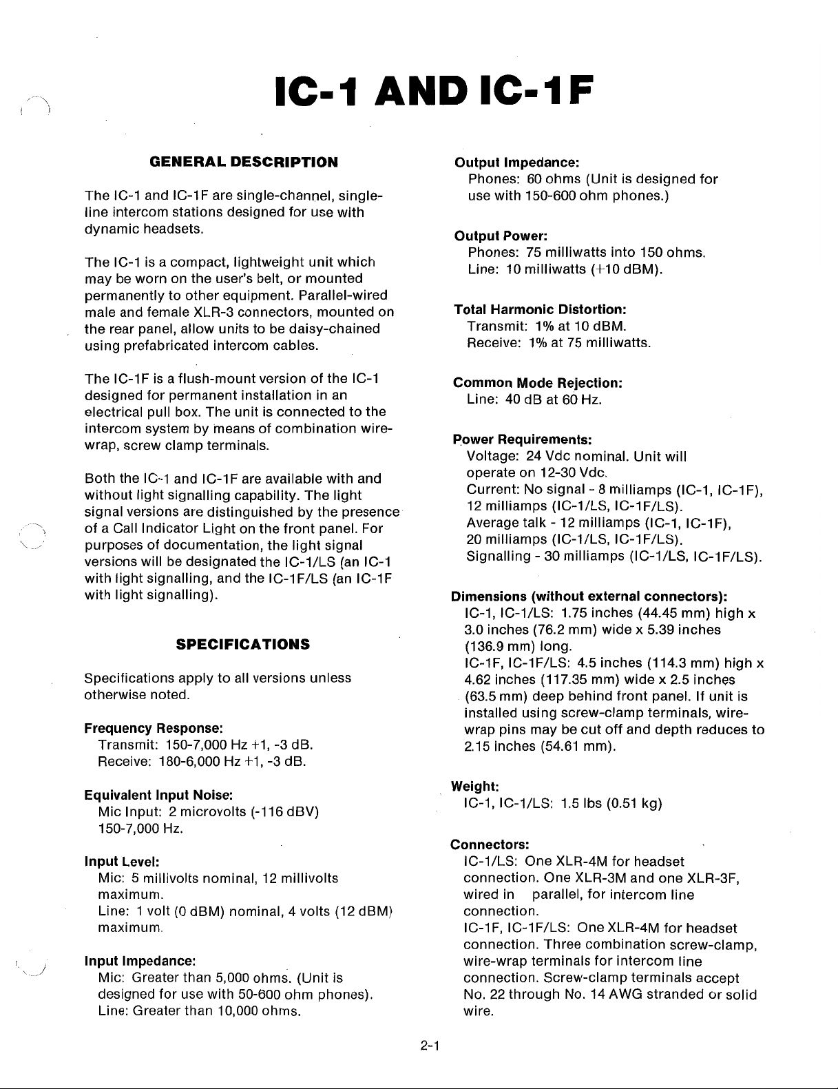
HEADPHONE VOLUME
CONTROL
MICROPHONE ON/OFF
IC-1 FRONT PANEL
HEADPHONE VOLUME
CONTROL
OPERATION
Headset Jack:
Accepts headsets with dynamic
microphone and dynamic headphone(s).
Headphone VOLUME Control:
Adjusts
headphone listen level. Does not affect mic level.
MICION Switch (IC-1, IC-IF):
In the MIC
position, the microphone is shut off but the
intercom line is still monitored by the phones. In
the ON position, the microphone is operational
for two-way communication.
OFFIMICICALL Switch (IC-IILS, IC-1 FILS):
the
OFF
position, the microphone is shut off but
In
the intercom line is still monitored by the phones.
In the MIC position, the microphone is
operational for two-way communication. In the
CALL position, with the switch held continuously,
an inaudible signal is sent to all other stations on
the line: on those stations with light signalling,
the Call Indicator lights will illuminate. When
another station responds verbally, release the
switch and it will automatically return to the MIC
position for two-way communication.
Call Indicator LED (IC-1/LS, IC-1FILS):
Illuminates when station is being called. Does not
illuminate when sending a call signal.
CALL INDICATOR LIGHT
IC-1ILS FRONT PANEL
INTERCOM LINE CONNECTORS
REAR PANEL
J
IC-1 Reference Guide
Page 3
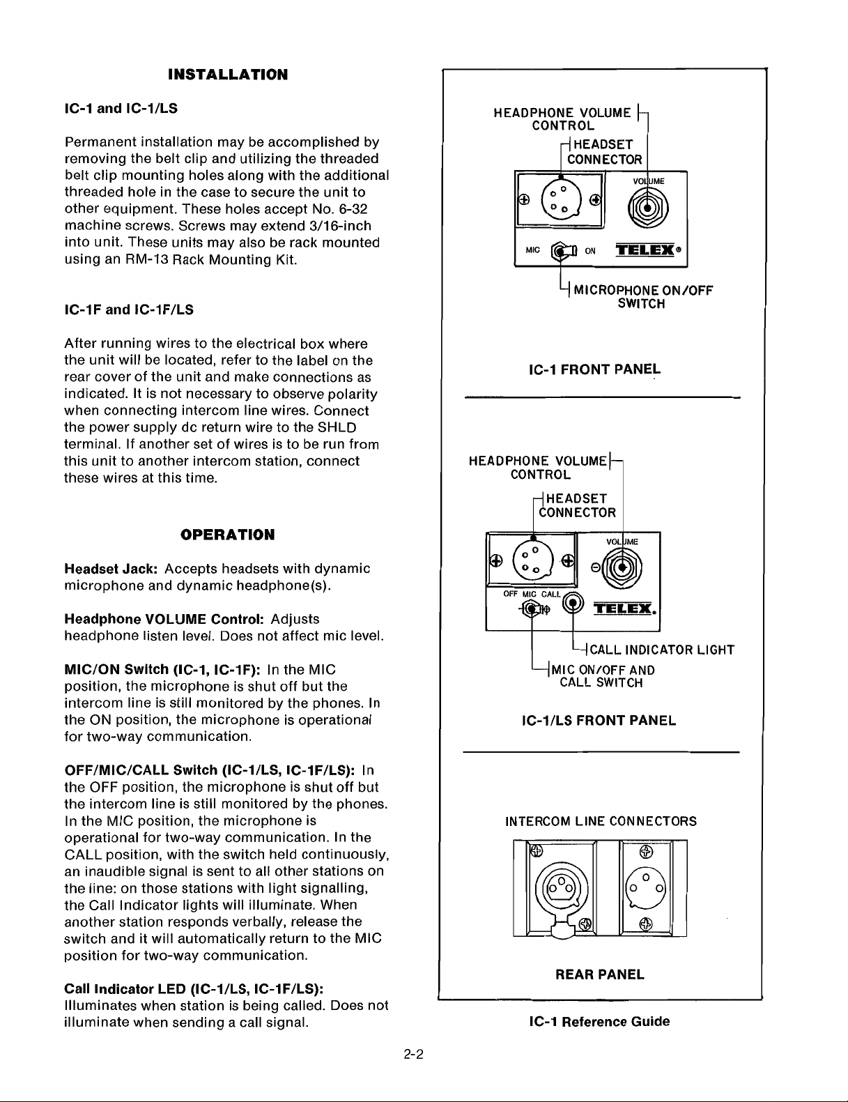
MICROPHONE
ON/OFF SWITCH
HEADPHONE VOLUME CONTROL
CONTROL
HEADSET CONNECTOR
MIC ON/OFFAND
CALL SWITCH
IC-IF FRONT PANEL
IC-1FILS FRONT PANEL
-.---
IC-IF Reference Guide
Page 4

MAINTENANCE
IC-1, IC-IILS Mechanical Exploded
2-4
View
Page 5

IC-I, IC-IILS Mechanical Parts List
ITEM NO.
1
*
2
3**
4*
*
5**
6
7
8
9
10
11**
12**
13
14
15*
**
16
17
18
19*
* *
20
21
22
23
24
25
DESCRIPTION
Bezel
Nut, Hex No. 3/8-32
LED
Lens, LED
Clip, Lens Mtg.
Screw No. 4-40
x
!4
Connector, XLR-4M (J2)
PCB Assembly, Audio
Screw, No. 4-40
x
!4
Connector, 14-Position (J1)
Pin, Snap In (Not Shown)
Connector (J5)
Pin, Snap In (Not Shown)
PCB Assembly, 20 kHz Light Signal
Screw, No. 4-40 x 1
!4
Spacer, Hex, 15/16-inch
Switch, Toggle, SPDT (wlhardware) (S1)
Switch, Toggle, SPDT (w/hardware) (S1)
Connector, XLR-3F (J3)
Connector, XLR-3M (J4)
Screw, No. 6-32 x
%
Housing, Remote
Housing, Remote
Clip, Belt
Washer, Lock, Ext. Tooth, No. 6
Screw, No. 6-32 x
1/4
Potentiometer, IOOK, %W, +20°/o (R22)
Washer, Lock, Int. Tooth, No.
3/8
Chassis
PART NO.
95220-000
50033-001
58683-000
59739-000
53627-002
51 847-1 11
50994-004
92847-005
51 849-01 1
52264-01 4
54460-000
52264-007
54460-000
96080-000
51 845-046
6341 0-002
57481 -000
57481 -003
50995-003
50994-003
51 847-1 22
92874-003
92874-004
92873-001
50049-001
54993-074
571 45-001
5001 4-004
92854-000
92852,
92853.
Rev
Rev
*
Units without light signalling only.
**
Units with light signalling only.
F
W
Page 6

IC-1
F,
IC-1 FILS Mechanical Exploded View
2-6
Page 7

IC-IF, IC-1FILS Mechanical Parts List
,/
-\d
ITEM NO.
DESCRIPTION
PART NO.
1
2
3
4
5*
*
6*
*
7
8
9*
10
11
12
13
14**
15
16*
* *
17*
* *
18
19
20
2 1
22
23
24
25
26**
27
28
Nut, Hex, No. 3/8-32
Collet
Knob, Control
Cap
Lens, LED
LED
Screw, No. 4-40 x
!4
Connector, XLR-4M (J2)
Bezel
Screw, No. 6-32 x
3/8
Cover Plate, Front
Bracket
Washer, Lock, Int. Tooth, No.
4
Screw, No. 4-40 x 3/16
PCB Assembly, Audio
Switch, Toggle, SPDT (w/hardware) (S1)
Switch, Toggle, SPDT (w/hardware) (SI)
Cover, Rear
Cover, Rear
Screw, 4-40
x
'/2
Spacer, 3/16 Ig
Clip, LED Mtg.
Potentiometer, look,
%W,
f20°/o (R22)
Connector, 14-Position (JI)
Terminal (Not Shown, For J1)
Washer, Lock, Int. Tooth, No.
3/8
Connector, 7-Position (J5)
Terminal, (Not Shown, For J5)
Nut, Hex, No. 4
PCB Assembly, 20 kHz Light Signal
Angle Bracket
x
Screw, 4-40
!A
50033-001
53434-1 01
53432-1 16
53433-1 15
59739-000
58683-000
51 847-1 11
50994-004
9521 8-000
51 847-1 24
92857-000
92859-000
5001 4-002
51 845-037
92847-004
57481-000
57481 -003
92862-003
92862-004
51 845-041
57798-000
53627-002
571 45-000
52264-01 4
54460-000
5001 4-004
52264-007
54460-000
521 88-006
96080-000
9521 5-000
51 845-038
92863,
Rev
*Units without light signaling only.
**Units with light signaling only.
AB
Page 8

92846.
Rev
R
IC-I Audio PCB Assembly Component Layout
96079.
Rev
H
IC-IILS, IC-IFILS
20
KHz Light Signal PCB Assembly Component Layout
2-8
Page 9

IC-I
Audio
All resistors in ohms,
PCB Assembly Parts
1/4
watt, +5% unless otherwise noted.
List
All capacitors are in microfarads unless otherwise noted.
REFERENCE NO.
C1
C2,21
C5,11
C6,9,12
C7
C8,14
C13
C15
C16,23
C17
C18
C22
J
1
J
2
J
3
J
4
Q
1
R1
R 2
R3,4
R5,6,7,8
R9
R10
R11,15
R12,16
R13,18,19
R14,20
R17
R18,19
R22
R23
S
1
TI
U 1
U2
DESCRIPTION
Capacitor, 1, 35V, Tantalum
Capacitor, 0.01, 1 OOV
Capacitor, 10, 25V Electrolytic
Capacitor, 0.1
Capacitor, 47 pF
Capacitor, 100 pF
Capacitor, 0.001
Capacitor, 220 pF
Capacitor, 4.7, 25V Electrolytic
Capacitor, 10, 10V Electrolytic
Capacitor, 10, 50V Electrolytic
Capacitor, 1, 50V Electrolytic
Connector, 12-Pin
Connector, XLR-4M
Connector, XLR-3F
Connector, XLR-3M
Transistor, 2N2925
Resistor, 470 Ohm
Resistor, 220 Ohm
Resistor, 68K
Resistor, 150K
Resistor, 330 Ohm
Resistor, 2.7K
Resistor, 220K
Resistor, 1 M
Resistor, 100K
Resistor, 47K
Resistor, 2.7K
Resistor, 1 OOK
Potentiometer, 100K,
%W,
20%
Resistor, 10K
Switch, Toggle SPST
Transformer
IC, Low Noise Preamplifier, AN360
IC, Dual Low Noise Op Amp, NE5532
PART NO.
52257-049
521 57-251
51 821-020
52708-024
521 57-004
521 57-008
521 57-022
521 57-01 2
51 821-081
51 821-045
51 821-524
51821-106
52264-012
50994-001
50995-000
50994-000
51 547-000
521 54-289
521 54-297
521 54-237
521 54-229
521 54-293
521 54-271
521 54-225
521 54-209
521 54-233
521 54-241
521 54-271
521 54-233
571 45-002
521 54-257
57481 -000
56741 -000
53270-000
53295-000
92847,
Rev
Y
Page 10

IC-I/LS, IC-IF/LS
All resistors in ohms,
All capacitors are in microfarads unless otherwise noted.
20
KHz
Light Signal PCB Assembly Parts List
'/4
W,
+5% unless otherwise noted.
REFERENCE NO.
C1,2,3
C4
C5,7,9
C6
C8
C10
C11
CR1
J
5
Q1,3
Q2
R1
R2,5
R3,15
R4
R6
R7
R8
R11
R12
R14
U
1
VR1
DESCRIPTION
Capacitor, Ceramic, 0.001, 50V,
Capacitor, Ceramic, 100 pF, 500V,
Capacitor, Tantalum, 0.1, 35V, f20°/o
Capacitor NPO, Ceramic, 0.0022, 50V, k2%
Capacitor, Electrolytic, 4.7, 25V, +20°/0
Capacitor, Electrolytic, 10, 25V, +20%
Capacitor, Ceramic, 0.047, 25V, +80 -20%
Diode, 1 N4148
Connector, 7-Position
Transistor, 2N2925
Transistor, J175
Resistor, 2.2M
Resistor, 1M
Resistor, 20K
Resistor, 1 OK
Resistor, 62K
Resistor, 1 OK
Resistor, 47K
Resistor, 24K,
Resistor, Variable, 5K,
Resistor, 1.2K,
Socket, &Pin
%W,
+2%
%W,
klOO/o
flOO/o
+lOO/o
PART NO.
52676-1 01
521 57-008
52257-065
35694-034
52723-01 3
52723-01 4
521 58-033
52228-000
57721 -007
51 547-000
54687-001
521 54-201
521 54-209
521 54-250
521 54-257
521 54-238
521 54-257
521 54-241
521 55-248
571 48-048
521 54-456
53258-000
51302-01 7
53041 -002
Page 11

MICROPHONE PRE-AMPLIFIER 16V/19V LINE AMPLIFIER
I
I
HEADPHONE AMPLIFIER
--
NOTES:
1.
ALL RESISTORS IN OHMS,
2.
ALL CAPACITORS IN MICROFARADS UNLESS OTHERWISE NOTED.
3.
ALL VOLTAGES ARE DC MEASURED USING A HIGH IMPEDANCE METER UNDER NO-SIGNAL
CONDITIONS WlTH CHASSIS AS REFERENCE.
4.
WHERE TWO VOLTAGES ARE INDICATED, THE FIRST IS WlTH A HEADSET CONNECTED AT J2
AND THE SECOND IS WITHOUT.
5.
--t-
6.
THIS SCHEMATIC SUBJECT TO CHANGE TO ACCOMMODATE DESIGN IMPROVEMENTS.
INDICATES RECEIVE SIGNAL PATH. INDICATES TRANSMIT SIGNAL PATH.
1/4
WATT,
+5%
UNLESS OTHERWISE NOTED.
I
'a
Page 12

NOTES:
1. ALL RESISTORS IN OHMS, % WATT, f5% UNLESS OTHERWISE NOTED.
2. ALL CAPACITORS IN MICROFARADS UNLESS OTHERWISE NOTED.
3.
ALL VOLTAGES ARE DC MEASURED USING A HIGH IMPEDANCE METER
WlTH CHASSIS AS REFERENCE.
4. WHERE TWO VOLTAGES ARE INDICATED, THE UPPER
SIGNAL AT P5-4 AND THE LOWER IS WlTH 20 KHz AT 100 MV (CALL
SIGNAL IN) AT P5-4.
5. ALL SINGLE VOLTAGES REPRESENT NO-SIGNAL CONDITIONS.
6.
20 KHz ADJUSTMENT: CONNECT FREQUENCY METER BETWEEN ANODE
OF CR1 AND CHASSISADJUST R12 FOR A READING OF 20 KHz i100 Hz.
7.
THIS SCHEMATIC SUBJECT TO CHANGE TO ACCOMMODATE DESIGN
IMPROVEMENTS.
is
WlTH NO
 Loading...