

Page 1

Application Guide
Kenwood Radio
Series 80, 90 and 150/180
To IP-223
November 4, 2005 P/N AN-VEGA-1 Rev D
Page 2

II IP-223 to Kenwood Radios
Table of Contents
1
General ...................................................................................1
2 Setup.......................................................................................1
2.1 TK-x150/180 Model Cable Assembly:...........................................................................1
2.2 TK-x80 Model Cable Assembly:....................................................................................1
2.2.1 IP223 Rev F or higher Board Configuration: ......................................................... 2
2.2.2 IP223 Rev A to Rev E Board Modifications: ......................................................... 2
2.3 TK-x90 Model Cable Assembly:....................................................................................2
2.3.1 IP223 Rev F or higher Board Configuration: ......................................................... 2
2.3.2 IP223 Rev A to Rev E Board Modifications: ......................................................... 3
2.4 IP223 Configuration: ...................................................................................................... 4
2.4.1 Per-line setup screen............................................................................................... 4
2.4.2 IP223 Jumper settings............................................................................................. 4
2.5 Radio Configuration........................................................................................................5
2.5.1 TK-x80 Series......................................................................................................... 5
2.5.2 TK-x90 Series......................................................................................................... 6
2.5.3 TK-x150/180 Series................................................................................................ 8
Page 3

IP-223 to Kenwood Radios 1
1 General
The application note is intended to show how to assemble the cable and setup the hardware of
the IP223 for channel change and FleetSync applications using Kenwood radio.
2 Setup
2.1 TK-x150/180 Model Cable Assembly:
NOTE: There are differences between the TK-x150 and TK-x180 radios DB25 connectors.
If COR is used, pin 20 (TK-x150 an output only) will be programmed for that function and
the cable will route that signal to the IP-223. On the TK-x180 the same pin is a general
purpose I/O and has an additional 470 ohm series resistance added. This requires that the IP223 external pull-up resistance must be removed. Jumpers J8 (Line 1) and J30 (Line 2)
should be placed in a neutral position (neither A or B, hanging).
The tables below show the assembly cable for the TK-x150 model radios.
Signal IP223 DB25 TK-x150 Radio DB25
Ground
PTT Common
PTT
COR
RX+
TX+
IP223 Serial
Signal
Line 1 Line 2
7 7
2 7
14 12 (Aux Input 4 Programmable)
20 20 (Aux Output 1 Programmable)
24 17
25 6
IP223 DB9
TK-x150 Radio DB25
TXD
RXD
For IP223 Rev F board or later make sure jumper J35 is in “A” position for line 1 and jumper
J26 is in “A” position for line 2.
2 8 2
3 7 3
2.2 TK-x80 Model Cable Assembly:
The KCT-19 accessory cable from Kenwood radio is needed and the 'E' connector is
connected to CN4 inside the radio to establish the serial communication.
The tables below show the assembly cable for the TK-x80 model radios.
Signal IP223 DB25 KCT-19 Accessory Conn.
Ground
PTT Common
PTT
COR
RX+
TX+
7 6
2 6
14 8
20 11
24 12
25 5
Page 4

2 IP-223 to Kenwood Radios
2.2.1 IP223 Rev F or higher Board Configuration:
Set the jumper J35 to B position for line 1 and the jumper J26 to B position for line 2
IP223 Serial
Signal
TXD
RXD
IP223 DB9
KCT-19 Accessory Conn.
Line 1 Line 2
9 4 14
1 6 15
2.2.2 IP223 Rev A to Rev E Board Modifications:
Lift Pin 12(line 1) or pin 9(line 2) of U45 according to the line selected and solder to its PCB
Pad. Please refer to the Figure 1 for better demonstration.
IP223 Serial
Signal
TXD
RXD
Pin on U45 of the board
KCT-19 Accessory Conn.
Line 1 Line 2
11 10 14
To the pad
of pin 12
To the pad
of pin 9
15
2.3 TK-x90 Model Cable Assembly:
The tables below show the assembly cable for the TK-x90 model radio.
Signal IP223 DB25 TK-x90 Radio DB25
Ground
PTT Common
PTT
COR
RX+
TX+
7 7
2 7
14 2 Aux Input (Programmable)
20 20 AO1 (Programmable)
24 17
25 13
2.3.1 IP223 Rev F or higher Board Configuration:
Set the jumper J35 to B position for line 1 and the jumper J26 to B position for line 2
IP223 Serial
Signal
TXD
RXD
IP223 DB9
TK-x90 Radio DB25
Line 1 Line 2
9 4 10
1 6 9
Page 5

IP-223 to Kenwood Radios 3
2.3.2 IP223 Rev A to Rev E Board Modifications:
Lift Pin 12(line 1) or pin 9(line 2) of U45 according to the line selected and solder to its PCB
Pad. Please refer to the Figure 1 for better demonstration.
IP223 Serial
Signal
TXD
RXD
Pin on U45 of the board
Line 1 Line 2
TK-x90 Radio DB25
11 10 10
To the pad of
pin 12
To the pad of
pin 9
9
Figure 1
Page 6

4 IP-223 to Kenwood Radios
2.4 IP223 Configuration:
Setup the desired IP223 line for Kenwood radio control at the following screen:
2.4.1 Per-line setup screen
C
B
A
Choose radio model in the Serial Port Mode box (A).
Change Serial Port Parameter box to 9600.N.8.2 (B).
Configure Talk Group and CHAN fields for channel change capability (C ).
2.4.2 IP223 Jumper settings
Line 1 Jumper setting Line 2
J33, J34
J16, J21
J14
J3, J9, J11
J13
J17, J22
“B”=4-wire
“A”=Single ended
“A”= 600
“A”=Single ended
“B” High
“B”= 600 ohms
J5, J6
J19, J20
J24
J25, J28, J29
J27
J10, J15
Page 7
IP-223 to Kenwood Radios 5
2.5 Radio Configuration
2.5.1 TK-x80 Series
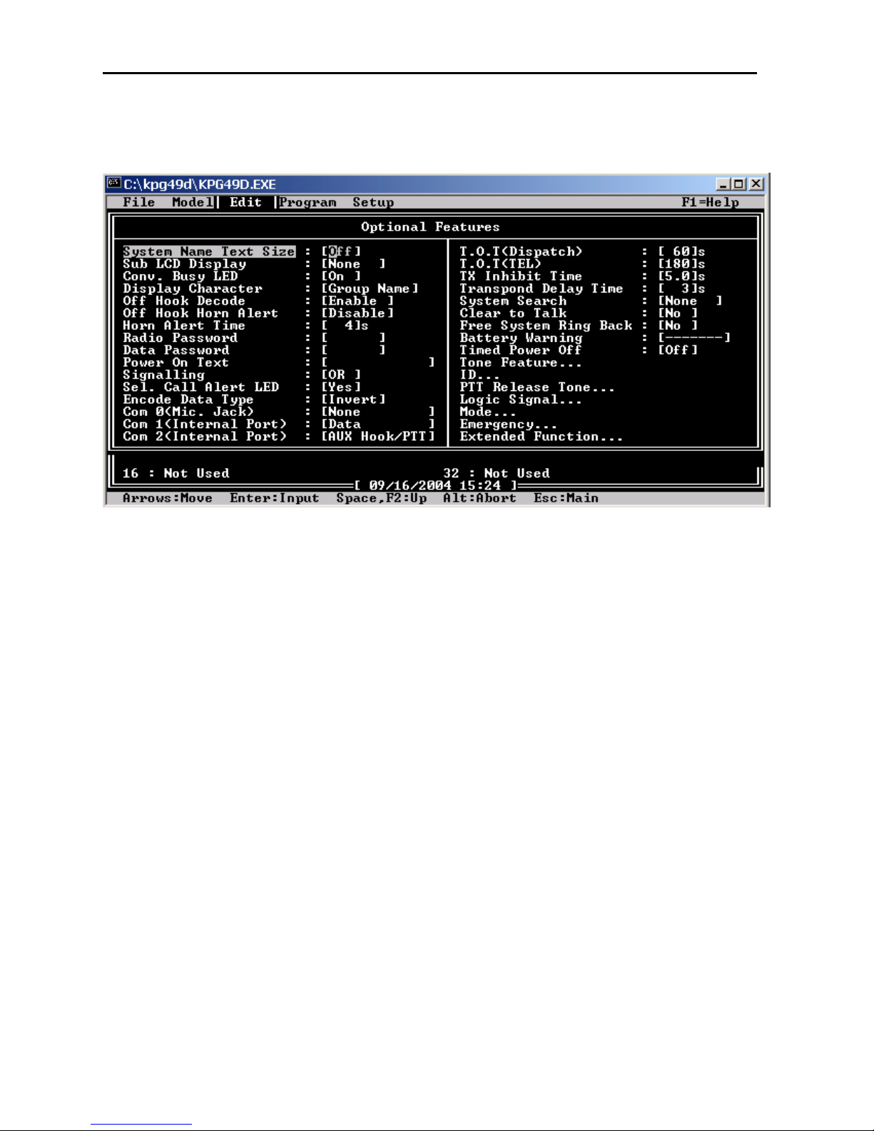
Program Com 1 for DATA
Page 8

6 IP-223 to Kenwood Radios
2.5.2 TK-x90 Series
Program Function Port, Input screen for Ext PTT in Radio 1 Al1.
Page 9
IP-223 to Kenwood Radios 7
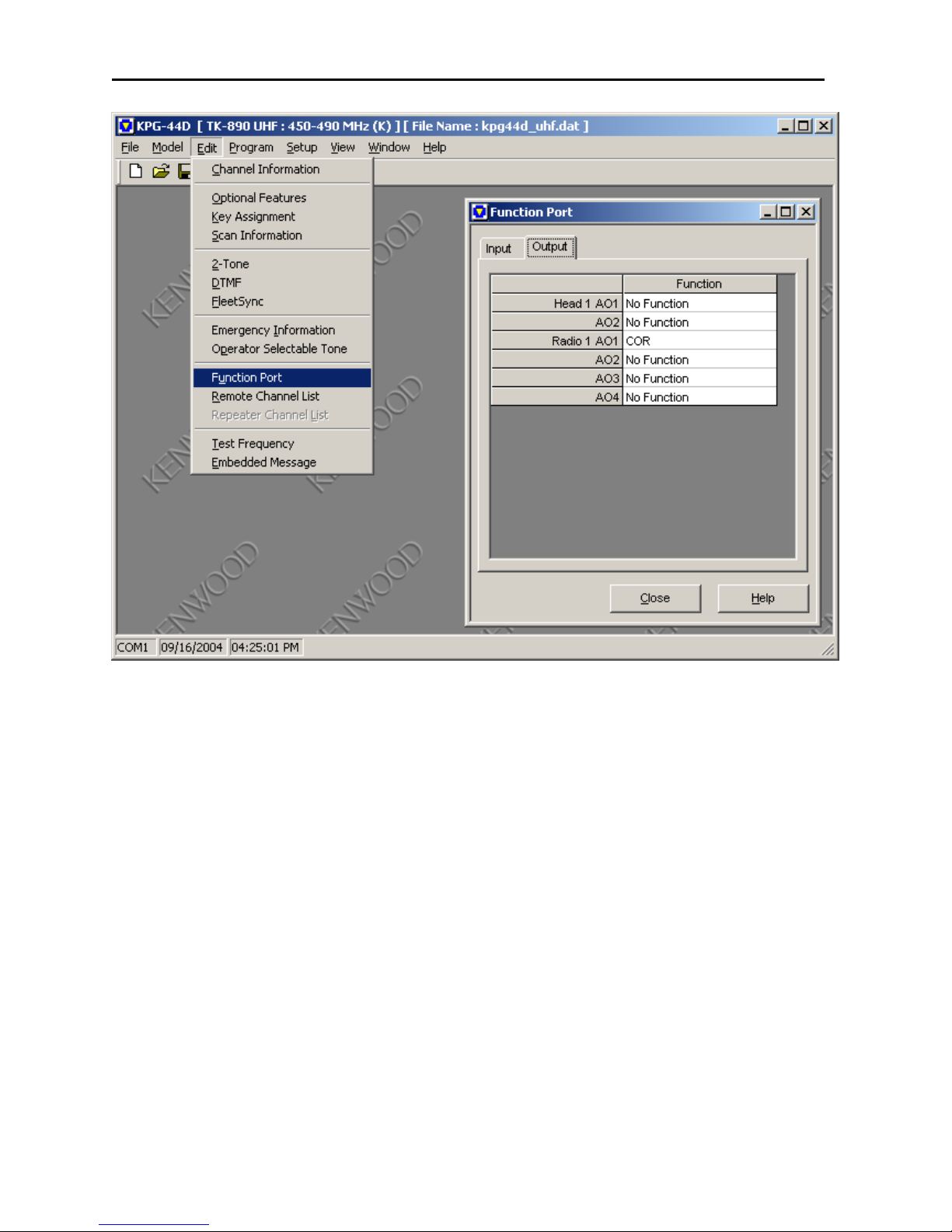
Program Function Port, Output screen for COR in Radio 1 AO1.
Page 10

8 IP-223 to Kenwood Radios
2.5.3 TK-x150/180 Series
Program Function Port, Aux Input for External PTT in AUX Input4 location and COR in AUX
Output1.
Program Com 1 for DATA
Page 11

IP-223 to Kenwood Radios 9
For the TK-x180, the AUX programming screen is different. Please note that the same interface
cable is used for both the TK-x150 and TK-x180 radios. If COR is used, IP-223 Jumper 8 (Line
1) or Jumper 30 (Line 2) will have to be placed in a neutral position for the Aux port pin 20 on
the TK-x180 to function properly as COR.
TK-x180 auxiliary setup screen
Suggestions or Comments
We’d appreciate your input. Please send us your suggestions or comments concerning this application
note, by fax (402-467-3279) or e-mail them to
: vega@telex.com
Technical Support:
Email address: acttechsupport@us.telex.com
Phone #: 1-800-898-6723
TELEX Communications, Inc.
Vega Signaling Products
8601 East Cornhusker Highway, Lincoln, Nebraska, 68507
Phone: (800) 752-7560 Fax: (402) 467-3279
E-mail: vega@telex.com, Web: www.vega-signaling.com
 Loading...