

Page 1

Telex
®
TELEX COMMUNICATIONS, INC. 12000 Portland Ave. South, Burnsville, MN 55337
Instruction Sheet
General Description
The SC-600 Amplified Broadband Splitter-Combiner makes it possible to operate eight
UHF wireless intercom transceivers using only
two antennas.
SPECIFICATIONS
Frequency Range ....................................................................................................520-760 MHz
Antenna Connectors ...........................................................................Standard TNC Receptacles
AC Power Input ........................................................................110\220 VAC 50\60Hz, 130 VA
DC Power Output: ..................................................................................................15 VDC 1.3A
Size (Approximate)...............H: 3.50" (88.9mm), W: 17.00" (431.8mm) D: 12.50" (317.5mm)
Weight: (Approximate) .......................................................................................................15 lbs.
CAT. NO. 71197000
AMPLIFIED BROADBAND UHF
ANTENNA SPLITTER-COMBINER
It also features a high degree of output isolation;
a necessity in multi-frequency systems to prevent intermodulation
DO NOT attempt to install and/or turn on the
power to the SC-600 until you have read completely and understood this manual.
SC-600
PN 801547
Antenna Splitter
3rd Order Intercept Output:.........................................................................Greater than 28 dBm
Net Gain............................................................................................................Greater than 2 dB
Noise Figure ..........................................................................................................Less than 4 dB
Output Isolation ..............................................................................................Greater than 20 dB
Antenna Combiner
Net Gain .................................................................................................................................0 dB
Noise Figure .................................................................................................................10 dB Typ
3rd Order Intermodulation .........................................................................-55 dbm @ + 13 dbm
Input, Each Transmitter
SC-600 Product Features:
· Ideal compliment to your BTR-600/BTR-500 UHF Wireless Intercom System
· Standard IEC 320 Power Input Connector
· Power Output for up to eight transceivers help make your whole system easier
to handle
· High-quality TNC Connectors ensure consistent impedance across the entire
frequency range
·
Rack Mount Brackets included for 19" (482.6mm) rack
-1-
Page 2
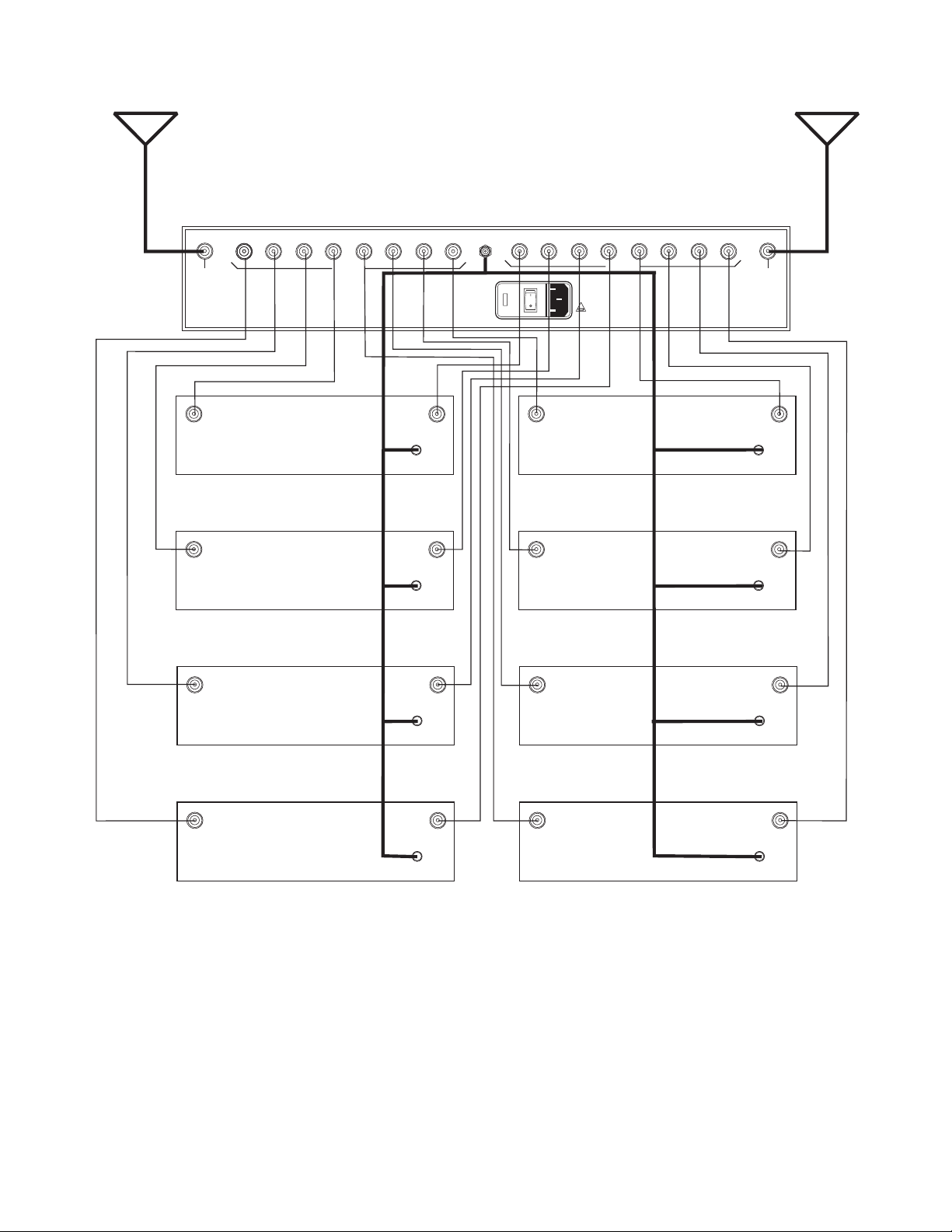
System Configuration
Figure 2 illustrates the typical system configuration using the SC-600.
SPECIAL NOTE: In any system, unused splitter
outputs should be terminated with a 50 ohm
“dummy load”. See the accessories listing at the
end of this manual.
R
SC - 600
elex
T
UHF ANTENNA SPLITTER/COMBINER
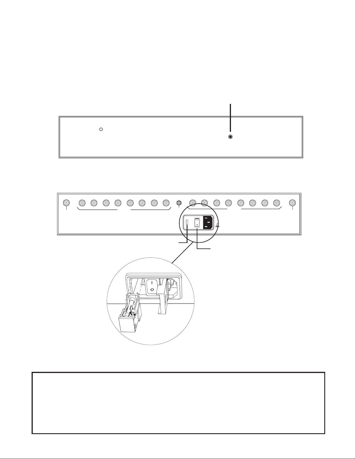
Front View
Power Supply
The SC-600 is equipped with an internal
110/220 VAC @ 50/60 Hz power supply that is
rated with a minimum output of 15 VDC at 1.3
amps. A standard IEC320 power input connector
is provided to reduce external wiring.
POWER ON/OFF LED
TRANSMIT
ANTENNA
TRANSMIT
DC
OUTPUT
FUSE BOX
110/220 VAC INPUT
Figure 1
Front and Rear View
110/220 VAC INPUT
Rear View
RECEIVE
FUSE: F 1.5A 250V
POWER ON/OFF
RECEIVE
ANTENNA
110/220 Volt Operation
Operation in either 110 VAC or 220 VAC is easily achieved. If the voltage indicated on the
fuse box does not match the voltage you are operating in, the fuse must be changed. Open the
fuse box door to remove and rotate the fuse holder. Make sure the voltage indicted, when the
fuse box door is closed, matches your operation voltage. refer to Figure 1.
-2-
Page 3
TRANSMIT
ANTENNA
RECEIVE
ANTENNA
TRANSMIT
ANTENNA
TRANSMIT 1
TRANSMIT 3
TRANSMIT
RECEIVETRANSMIT
POWER
RECEIVETRANSMIT
POWER
RECEIVETRANSMIT
DC
OUTPUT
110/220 VAC INPUT
FUSE: F 1.5A 250V
TRANSMIT 2
TRANSMIT 4
RECEIVE
RECEIVE
ANTENNA
RECEIVETRANSMIT
POWER
RECEIVETRANSMIT
POWER
RECEIVETRANSMIT
TRANSMIT 5
TRANSMIT 7
POWER
RECEIVETRANSMIT
POWER
Figure 2
System Configuration
POWER
TRANSMIT 6
RECEIVETRANSMIT
POWER
TRANSMIT 8
-3-
Page 4

Antenna Requirements
The SC-600 may be used with a variety of antennas. For best results, use a pair of ALP-450
directional log periodic antennas (See Figure 3)
or, the ALP-600 Bi-directional log periodic antenna (See Figure 4).
R
ex
T
el
ALP-450
THIS END TOWARD TRANSMITTER
Good results may be obtained with 1/2 wave antennas (See Figure 5). All antennas are sold separately.
When using 1/2 wave antennas, we recommend
using the higher frequency model when the receivers operate in more than one band. If the receivers are more than one band apart, such as
yellow and white, we strongly recommend using
the ALP-450, or ALP-600 depending on the application.
elex
T
Figure 3
ALP-450
1/2 Wave Antenna Placement
If 1/2 wave antennas are mounted directly to the
SC-600, they should be configured as shown in
Figure 6.
TRANSMIT
ANTENNA
TRANSMIT
Figure 4
ALP-600
Figure 5
1/2 Wave Antenna
Do not rack mount the SC-600 in this configuration. Serious loss of range and performance may occur.
Place the SC-600 with antennas in a location
that is in direct view of the transmitters for best
results.
OUTPUT
DC
110/220VAC INPUT
RECEIVE
FUSE: F 1.5A 250V
RECEIVE
ANTENNA
Figure 6
1/2 Wave Antenna Mounting
-4-
Page 5

Antenna Placement
for Optimum Range and Rack Mounting
Rack Mounting
For maximum range and when rack mounting,
the antennas must be remotely located.
The ALP-450 and ALP-600 antennas come complete with a variety of mounting hardware and
10 feet (3 meters) of low loss coaxial cable. A
combination mounting bracket with 10 feet of
coaxial cable is available for the 1/2 wave antenna (Model No. AB-2).
Antennas should be placed in a location with a
clear “signal path” to the transmitter. This
“path” should be as short and free of obstructions as possible. Obstructions, such as walls
ceilings, and metal objects, will reduce range
and performance.
NOTE: The SC-600 should always be
mounted on the bottom of the rack to fully
support the chassis. Failure to do this may result in damage to the SC-600.
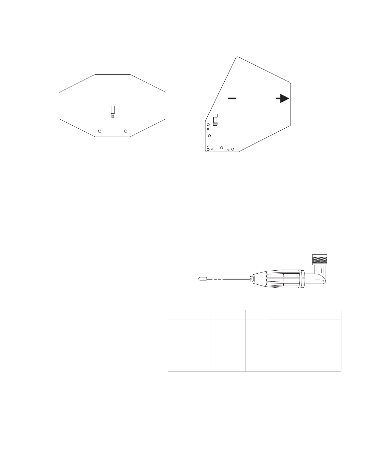
Rack mount brackets are supplied with the
SC-600. To attach the brackets, proceed as follows:
· Align the rack bracket with the holes on
the side of the unit. See Figure 7.
· Install flat head machine screws in two
holes. Tighten securely. Repeat on the
other side of the unit. For best alignment,
perform the above steps while the unit and
rack brackets are setting on a flat surface.
· Insert the unit into a 19" rack enclosure
and insert four #10-32 x 3/8" Phillips pan
head screws (supplied) in each corner of
the rack mount brackets and secure.
Figure 7
Rack Mounting
Coax Cable
For best results, it is recommended that cable
losses be kept under 4 dB. (Every 3 dB of signal
loss results in a system operating distance reduction of 25%.
See the accessories section of this manual for
special low loss cable assemblies.
-5-
Page 6
SC-600 Accessories and Replacement Parts
R
ex
T
el
elex
T
ALP-450
THIS END TOWARD TRANSMITTER
ALP-600
520-760 MHz Bi-Directional log periodic antenna
Includes mounting hardware and 10 feet (3 meter) coaxial cable with TNC connectors
Order No. 878896
Special low loss antenna cables with
TNC connectors
Model Length Order No.
CXU-10 10 Ft. (3 meter) 690419
CXU-25 25 Ft. (7.6 meter) 71151-025
CXU-50 50 Ft. (15 meter) 71151-050
CXU-75 75 Ft. (23 meter) 71151-075
CXU-100 100 Ft.(30 meter) 71151-100
TP-2 50 OHM/TNC dummy load
(For unused outputs)
Part No. 650095
ALP-450
450-900 MHz Log Periodic Antenna
Includes mounting hardware and 10 feet (3 meter) coaxial cable with TNC connectors
Order No. 71147000
1/2 wave Antenna
Model No. Part No. Band Color Frequency
CLA-1 870658-1 Blue 520-564.9 MHz
CLA-2 870658-2 Yellow 565-614.9 MHz
CLA-3 870658-3 Red 615-659.9 MHz
CLA-4 870658-4 White 660-689.9 MHz
CLA-5 870658-5 Green 690-724.9 MHz
CLA-6 870658-6 Orange 725-760 MHz
IEC 320 Cordsets
Type Part No.
230V 50 Hz (Euro) 58349008
230V 50 Hz (U.K.) 550024004
120V 60 Hz (U.S.) 8800102668
-6-
Page 7

Telex
Antenna Bracket Kit
Aluminum Brackets with vertical or horizontal
mounting capability
Order No. 878898
Antenna Mast
Four section, clear anodized aluminum mast
with extended length of 90 1/4"
Order No. 878897-1
(Antenna not included)
PRINTED IN U.S.A.
Copyright© 2001 by Telex
TELEX COMMUNICATIONS, INC.
All rights reserved
NOV 2001
-7-
 Loading...