

Page 1
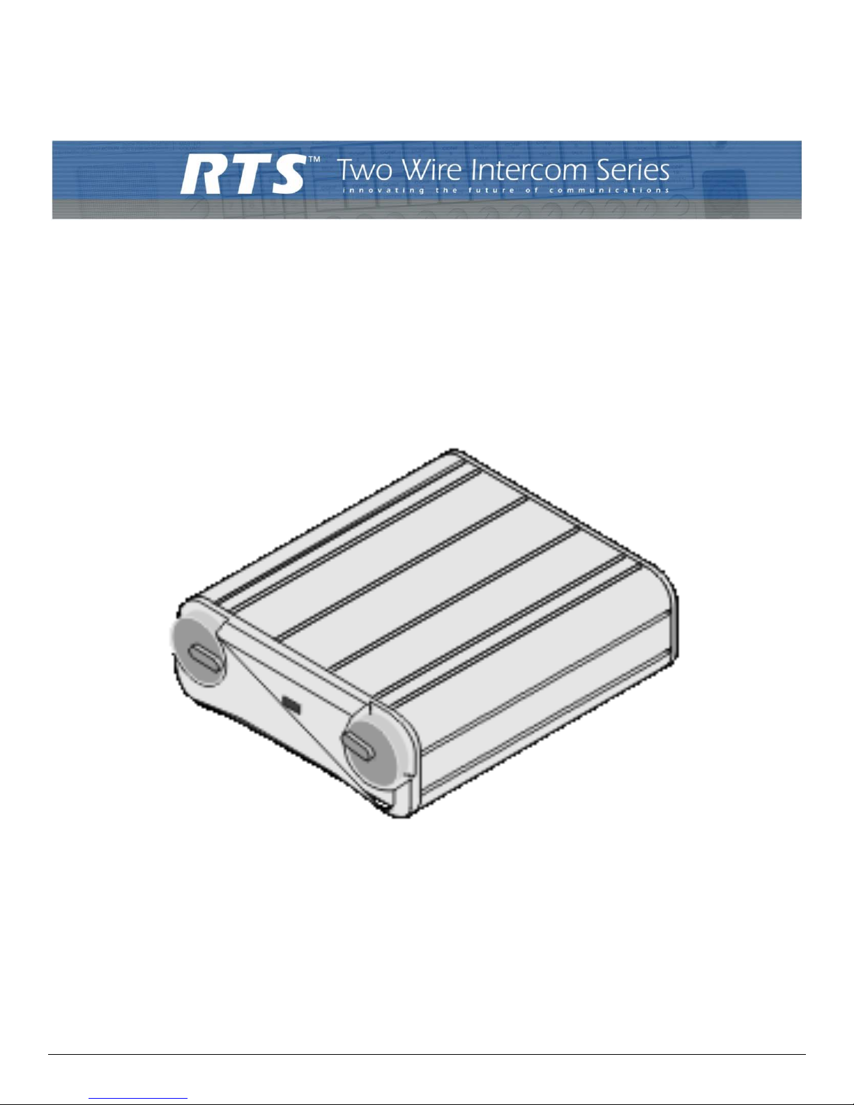
MODEL 4030
Two-Channel Listening Station
User Manual
9350-7489-000 Rev E 12/2005
Page 2

PROPRIETARY NOTICE
The RTS product information and design disclosed herein were originated by and
are the property of Telex Communications, Inc. Telex reserves all patent, proprietary design, manufacturing, reproduction, use and sales rights thereto, and to any
article disclosed therein, except to the extent rights are expressly granted to others.
COPYRIGHT NOTICE
Copyright 2005 by Telex Communications, Inc. All rights reserved. Reproduction
in whole or in part without prior written permission from Telex is prohibited.
UNPACKING AND INSPECTION
Immediately upon receipt of the equipment, inspect the shipping container and
the contents carefully for any discrepancies or damage. Should there be any,
notify the freight company and the dealer at once.
CUSTOMER SUPPORT
Technical questions should be directed to:
Customer Service Department
RTS/Telex Communication Inc.
12000 Portland Avenue South.
Burnsville, MN 55337 U.S.A.
Telephone: (800) 392-3497
Fax: (800) 323-0498
Factory Service: (800) 553-5992
Return Shipping Instructions
Customer Service Department
Telex Communications, Inc. (Lincoln, Nebraska)
Telephone: (402) 467-5321
Fax: (402) 467-3279
Factory Service: (800) 553-5992
Please include a note in the box which supplies the company name, address,
phone number, and a person to contact regarding the repair, the type and quantity
of equipment, a description of the problem and the serial number(s).
Shipping to the Manufacturer
All shipments of products should be made via UPS Ground, prepaid (you may
request from Factory Service a different shipment method). Any shipment
upgrades will be paid by the customer. The equipment should be shipped in the
original packing carton. If the original carton is not available, use any suitable
container that is rigid and of adequate size. If a substitute container is used, the
equipment should be wrapped in paper and surrounded with at least four inches of
excelsior or similar shock-absorbing material. All shipments must be sent to the
following address and must include the Proof of Purchase for warranty repair.
Upon completion of any repair the equipment will be returned via United Parcel
Service or specified shipper, collect.
Factory Service Department
Telex Communications, Inc.
8601 East Cornhusker Hwy.
Lincoln, NE 68507, U.S.A
Attn: Service
Page 3

Tabl
e
of
Contents
CHAPTER 1 .........................................................................................................................
DESCRIPTION AND SPECIFICATIONS ................................................................... 1
DESCRIPTION ........................................................................................................... 1
GENERAL ............................................................................................................... 1
FEATURES ............................................................................................................. 1
CONNECTIONS & CONTROLS .............................................................................. 2
SPECIFICATIONS ..................................................................................................... 3
GENERAL ............................................................................................................... 3
CHAPTER 2
OPERATION ............................................................................................................... 5
EXTERNAL CONNECTIONS & CONTROLS ........................................................ 5
CHAPTER 3
Parts Documentation and Schematic .......................................................................... 7
Page 4

2
Page 5

1
DESCRIPTION
CHAPTER 1
DESCRIPTION AND SPECIFICATIONS
DESCRIPTION
GENERAL
The Model 4030 is a portable user station for use with RTS/Telex two-wire or 4010 IFB intercom systems. The Model 4030 is
a listen-only IFB belt pack that can be used to listen to one or two intercom or program channels.
FEATURES
Features of the Model 4030 include:
• Powered externally, via the intercom system power supply on channel one
• Power-on indicator
• Headset/earset jack set for a wide range of operation
• Monaural phone jack for intercom channel one
Page 6
DESCRIPTION AND SPECIFICATIONS
2
• Stereo phone jack for intercom channels one and two
CONNECTIONS & CONTROLS
The Model 4030 has the following connections and controls:
• Detented intercom/program volume controls
• Headset connector that accepts 1/4" monaural phone plug
• Headset connector that accepts 1/4" stereo phone plug
• Channel connector that accepts an XLR type 3-pin connector for intercom line and power input
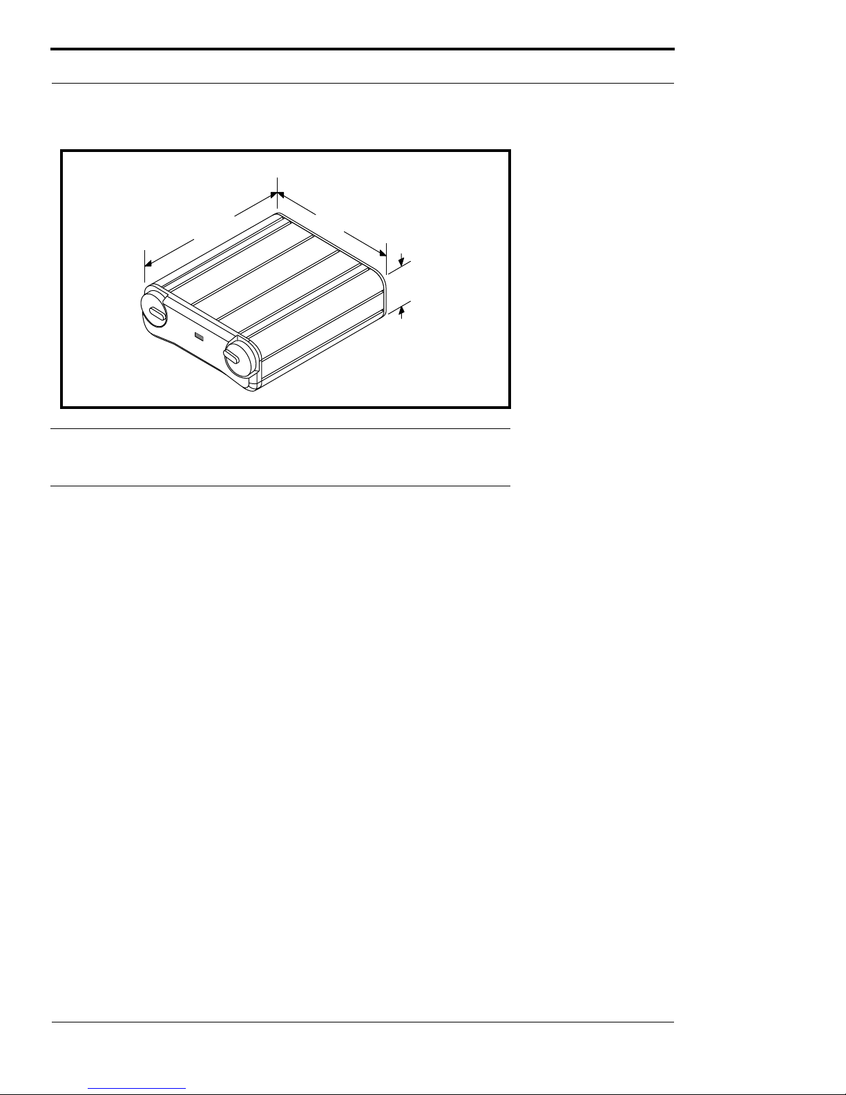
FIGURE 1. Dimensions
3.65"
92.7mm
3.75"
95.3 mm
1.5"
38 mm
Page 7

3
SPECIFICATIONS
SPECIFICATIONS
GENERAL
POWER REQUIREMENTS
32 VDC nominal (standard RTS line), 150mA maximum
Environmental Requirements
Storage: -20°C to 80°C, 0% to 95% humidity, noncondensing
Operating: 0°C to 50°C; 0% to 95% humidity, noncondensing
Dimensions
Physical : 3.65” (92.7mm) L x 3.75” (95.3mm) W x 1.5”
(38mm) D
Wei gh t
10.8 oz. (303 gr)
INTERFACE REQUIREMENTS
Earset / Headphone Compatibility
Accepts 50 to 600 ohm earsets or headphones
Audio Input Requirements
Input Level
2 V p-p (0dBu) nominal
Input Impedance
200 ohms ±5%
Noise Contribution
Less than -60 dB nominal
HEADPHONE AMPLIFIER
Voltage Gain
27 ±3dB from intercom channel to earset
Maximum Output
65 mW into 150 ohms
Frequency Response
250Hz to 8 kHz +1/-4dB
CONNECTOR PIN CONFIGURATIONS
Headset Connectors
Type: 1/4” Monaural Plug
Tip: Headset audio high
Sleeve: Headset audio low
Type: 1/4” Stereo Plug
Tip: Headset channel 1 audio high
Ring: Headset channel 2 audio high
Sleeve: Headset audio low
Audio/Power Connector
Type: XLR-3F
Pin 1 Common
Pin 2 Channel 1 audio and power input
Pin 3 Channel 2 audio
Page 8

DESCRIPTION AND SPECIFICATIONS
4
Page 9
5
EXTERNAL CONNECTIONS & CONTROLS
CHAPTER 2
OPERATION
EXTERNAL CONNECTIONS & CONTROLS
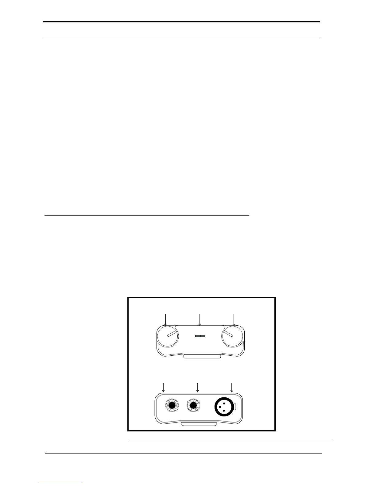
NOTE: The numbers refer to the callouts in Figure 2-1.
1. Channel One Volume Control
Use this control to adjust the headset/earset listen<R>level for channel one.
2. On Indicator
This LED glows green when the beltpack is connected to an intercom channel that is functioning.
3. Channel Two Volume Control
Use this control to adjust the headset/earset listen level for channel two.
FIGURE 2. Model 4030 Connections and Controls
HEADSET
LINE
STEREO
NONINTERRUPT
INTERRUPT
1
23
4
56
Page 10

OPERATION
6
4. Mono Headset Connector
This connector accepts a wide-response headset/earset, such as the RTS/Telex Model 2233 or Model 2234, with a 1/4"
monaural phone plug
5. Stereo Headset Connector
This connector accepts a wide-response headset/earset, such as the RTS/Telex Model 2233 or Model 2234, with a 1/4"
stereo phone plug
6. Intercom Channel Connectors
The Model 4030 intercom channel is connected via a 3-pin female connector. The Model 4030 is powered from the
intercom system power supply and will turn on with the intercom system.
Page 11

7
CHAPTER 3
Parts Documentation and Schematic
Parts may be obtained directly from Telex at:
Telex Communications, Inc.
12000 Portland Ave South
Burnsville, MN 55337 USA
Telephone: (800) 392-3497
Fax (800) 323-0498
Page 12
Parts Documentation and Schematic
8
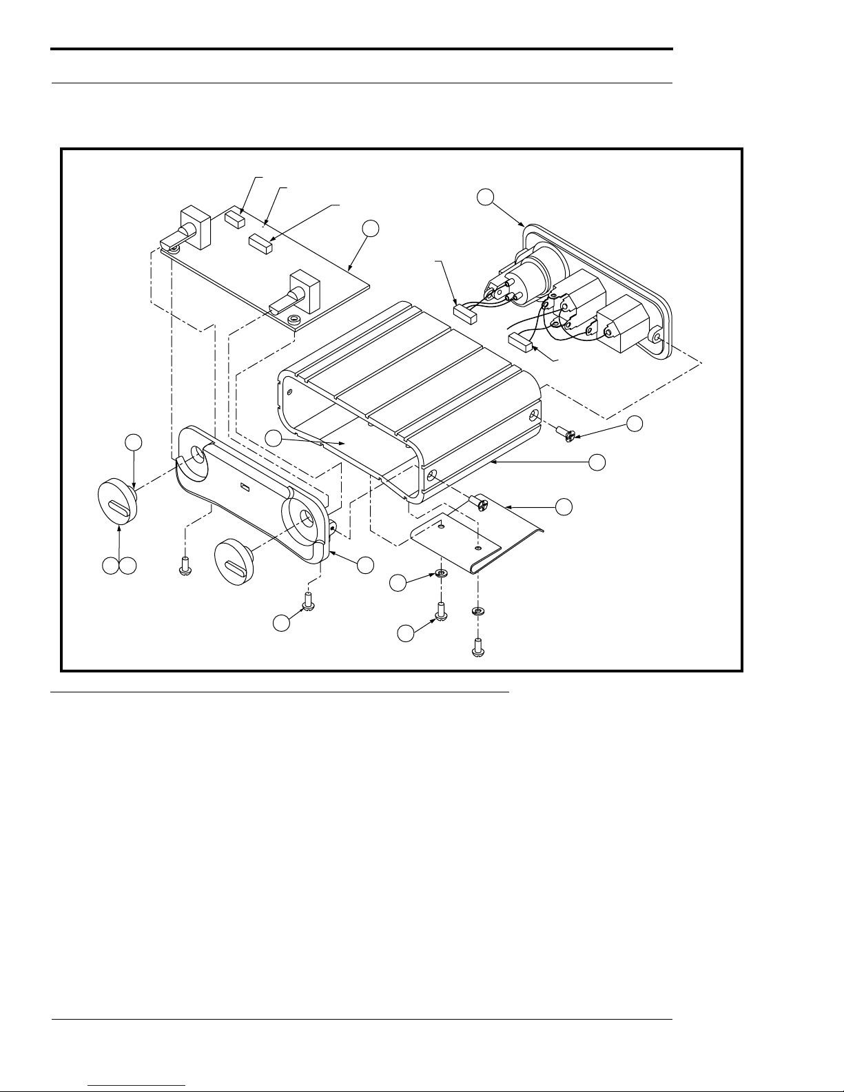
FIGURE 3. Final Assembly, Model 4030
1
7
10
11
9
8
2
4
TO J1
TO J2
J1
J2
TO TP 1
TP 1
65
( 2 PLS. )
( 2 PLS. )
( 4 PLS.)
( 2 PLS. )
( 2 PLS. )
12
NOTE 3
13
NOTE 1, 2
NOTES:
1. Put loctite, Superbonder, in body
of knobs prior to assembly.
2. Knobs to be indexed at 4 o'clock
position for minimum pot setting.
3. Install Valox insulator to inside of
case, top and bottom.
3
Item No. Description Part No
1 Case, 4030 9060-7374-009
2 Top Plate 9070-7489-002
3 Connector Plate Assy (see
page x for parts list)
9020-7489-001
4 Circuit Board Assembly (see
page x for parts list
9030-7477-002
5 Knob, Nylon Body 9160-563-601
6 Boot, Knob 9160-563-602
7 Screw, 4-40 x 0.25, Flat Head 800124-001
8 Belt Clip 358776
9 Screw, 4-40 x 0.25, Pan Head 51845-038
10 Screw, 4-40 x 0.1875, Pan
Head
51845-037
11 Washer, Lock, Split, #4 50086-004
12 Insulating Film Local Purchase
13 Loctite Superbonder (or
equiv)
Local Purchase
Item No. Description Part No
Page 13
9
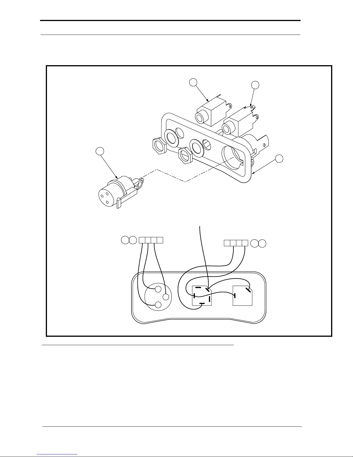
FIGURE 4. Connector Plate Assembly, Model 4030
10
2
3
1
1
2
3
4
1
2
3
J1
5
4
J2
1
2
3
4
5
4
LINE STEREO MONO
TO TP1 ON PC BOARD
Item No. Description Part No.
1 Connector Plate 90807374-008
2 Jack, Phone, Mono, 1/4” 2013001200
3 Connector, XLR-3F 40055-10
4 Connector, 4-pin 59958-004
5 Contact, Connector 59958-200
6-9 Not Used
10 Jack, Phone, Stereo, 1/4” 2013000300
Item No. Description Part No.
Page 14
Parts Documentation and Schematic
10
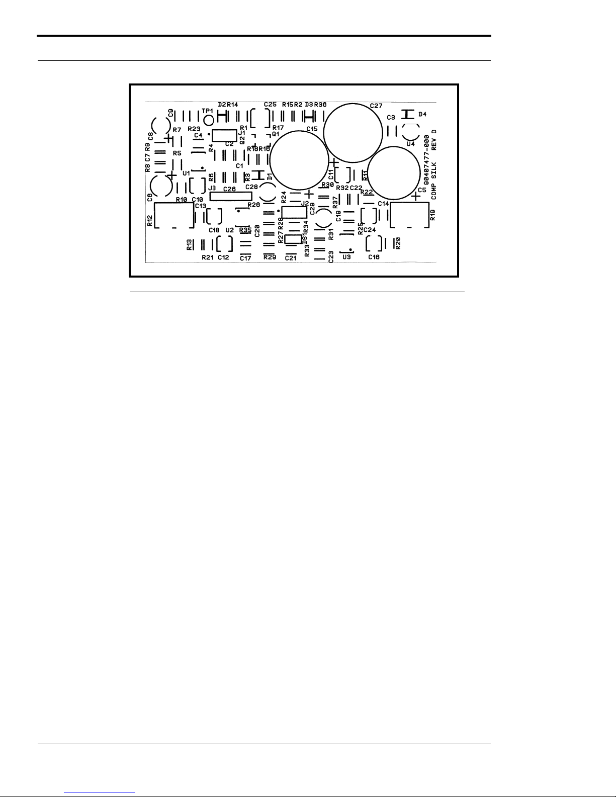
FIGURE 5. PC Board Assembly, Model 4030
Ref No. Description Part No.
C1, C2 Capacitor, CM, SM, 0.22 μF, 50V 102880-237
C3 Capacitor, CM, SM, 0.33 μF, 50V 102880-239
C4 Capacitor, CM, SM, 0.1 μF, 50V 102881-351
C5 Capacitor, LE, 2200 μF, 16V 517002-081
C6 Capacitor, EL, 100 μF, 25V 51821-626
C7 Capacitor, CM, SM, 0.01 μF, 50V 102881-339
C8 Capacitor, EL, 47 μF, 25V 51821-625
C9 Capacitor, CM, SM, 0.01 μF, 50V 102881-339
C10,C11 Capacitor, EL, SM, 1 μF, 50V 102884-606
C12 Capacitor, EL, SM, 0.1 μF, 50V 102884-600
C13,C14 Capacitor, CM, SM, 0.1 μF, 50V 102881-351
C15 Capacitor, LE, 2200 μF, 22V 517002-116
C16 Capacitor, EL, SM, 4.7 μF, 25V 102884-410
C17 Capacitor, CM, SM, 220 pF, 50V 102879-208
C18 Capacitor, EL, SM, 4.7 μF, 25V 102884-410
C19 Capacitor, CM, SM, 220 pF, 50V 102879-208
C20 C23
Capacitor, CM, SM, 0.1 μF, 50V 102881-351
C24 Capacitor, EL, SM, 0.1 μF, 50V 102884-600
C25 Capacitor, EL, SM, 10 μF, 25V 102884-412
C26 Capacitor, LE, 2200 μF, 25V 517002-116
C28,C29 Capacitor, NP, 10 μF, 25V 52710-078
D1 - D4 Diod, SM Switching, 914/4148 58711-100
DS1 LED, Rectangular, Green 58685-101
J1, J2 Connector, St Locking, 0.059, M-4 59958-104
J3 Connector, St Header, 0.100, M-5 590089-005
Q1, Q2 Transistor, SM, SI NPN, MMBTA13 54749-000
R1, R2 Resistor, SM, 22.1 kΩ, 1%, 1/8W 102404-333
R3 - R6 Not Used
R7 Resistor, SM, 10 kΩ, 1%, 1/8W 102404-300
R8 Resistor, SM, 22.1 kΩ, 5%, 1/8W 102513-103
R9 Resistor, SM, 10 kΩ, 1%, 1/8W 102404-300
R10,
R11
Resistor, SM, 4.7kΩ, 5%, 1/8W 102513-472
R12 Potentiometer, 10kΩ, 10%, 0.05 54131-005
R13 Resistor, SM, 10Ω, 5%, 1/8W 102513-100
R14,
R15
Resistor, SM, 47 kΩ, 5%, 1/8W 102513-473
R16 Resistor, SM, 10Ω, 5%, 1/8W 102513-100
R17 Resistor, SM, 150kΩ, 5%, 1/8W 102513-154
R18 Resistor, SM, 10
Ω, 5%, 1/8W 102513-100
R19 Potentiometer, 10kΩ, 10%, 0.05 54131-005
R20 Resistor, SM, 10Ω, 5%, 1/8W 102513-100
R21,
R22
Resistor, SM, 1kΩ, 1%, 1/8W 102404-200
R23 Resistor, SM, 0Ω, 5%, 1/8W 102513-000
R25 Resistor, SM, 100kΩ, 1%, 1/8W 102404-400
R26R33
Resistor, SM, 10Ω, 5%, 1/8W 102513-100
R34 Resistor, SM, 1kΩ, 5%, 1/8W 102513-102
R35 Resistor, SM, 100kΩ, 1%, 1/8W 102404-400
U1 IC, SM, Dual Op Amp, LM8333 16030833-SM
U2,U3 IC, SM, Low Pwr Audio Amp,
MC34119
16030146-SM
U4 IC, Voltage Regulator, 12V, 78L12
Support Bracket
64106003
Nut, Self-Cinching, 4-40 59832-002
Ref No. Description Part No.
 Loading...