

Page 1
Telex
RR
Op er ating In struc tions
RadioCom
™
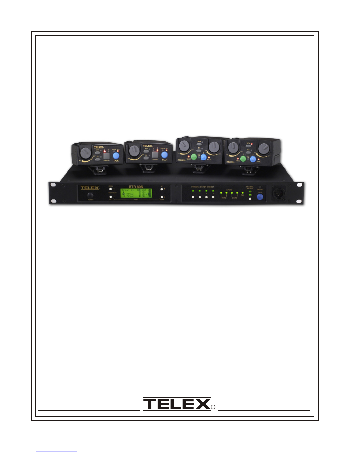
BTR-80N, TR-80N, TR-82N
Pro fes sional
Wire less
In ter com Sys tem
Page 2

Page 3

Ta ble of Con tents
1. In tro duc tion
Gen eral De scrip tion ........................................................................1-1
Sys tem Fea tures ...........................................................................1-1
2. BTR-80N Base Con trols and Con nec tions
Front Panel ...............................................................................2-1
Rear Panel................................................................................2-2
BTR-80N Spec i fi ca tions.....................................................................2-3
3. TR-80N Con trols and Con nec tions
Top Panel ................................................................................3-1
Rear Panel................................................................................3-2
TR-80N Spec i fi ca tions ......................................................................3-3
4. TR-82N Beltpack Con trols and Con nec tions
Top Panel ................................................................................4-1
Rear Panel................................................................................4-2
TR-82N Spec i fi ca tions ......................................................................4-3
5. Ini tial Set-Up
Un pack ing................................................................................5-1
An ten nas .................................................................................5-2
An tenna Con nec tion..................................................................5-2
An tenna Po lar iza tion .................................................................5-2
Dis tance Be tween An ten nas............................................................5-2
An tenna Place ment...................................................................5-2
Im prov ing Re cep tion/In creas ing Range...................................................5-4
6. BTR-80N Op er a tion
Ba sic Op er a tional De scrip tion ................................................................6-1
Sys tem Quick Start...................................................................6-1
In ter fac ing to the BTR-80N
Trans mit and Receive An ten nas.........................................................6-2
2-Wire In ter com Ports ................................................................6-2
4-Wire In ter com Ports ................................................................6-3
Aux il iary In put / Output ..............................................................6-3
Stage An nounce (SA) Relay ...........................................................6-4
Base Sta tion Link ....................................................................6-4
WTA Au dio ...................................................................6-5
CAN Bus .....................................................................6-5
Pro gram Jack .......................................................................6-5
Pow er ing the Base Station ...................................................................6-6
Start-Up Screen............................................................................6-6
Sta tus Screen..............................................................................6-6
RSSI Screen ..............................................................................6-6
Group / Chan nel Se lection ...................................................................6-7
Group / Chan nel Se lect ...............................................................6-7
Group / Fre quency Se lect..............................................................6-7
Fre quency Edit (User-De fined Groups Only) ..............................................6-7
Base Main Set tings .........................................................................6-8
Talk But ton.........................................................................6-8
Chan nel Se lect But ton ................................................................6-8
Lo cal Head set Vol ume and Gain ........................................................6-8
Base Transmit Power .................................................................6-8
Squelch Set tings.....................................................................6-9
Stage An nounce Level................................................................6-9
An tenna Power......................................................................6-9
CAN Bus Num ber ..................................................................6-10
-i-
Page 4

In ter com Set tings .........................................................................6-10
i. 2-Wire In ter com..................................................................6-10
ii. 4-Wire In ter com..................................................................6-11
Aux il iary Set tings .........................................................................6-11
ClearScan ...............................................................................6-12
Lock out.................................................................................6-12
Copy ...................................................................................6-12
t
s
1
Use De fault ...........................................................................6-12
Fac tory Re set ............................................................................6-12
Con nec tion of Mul ti ple Base Sta tions with Link Ca bles ...........................................6-13
Over-the-Air Data Links .............................................................6-13
Mas ter and Servant Base Sta tions ......................................................6-14
CAN Bus .........................................................................6-15
Base Sta tion Link Con fig u ra tions ......................................................6-15
Wire less Talk Around (WTA) Au dio Only ..........................................6-16
WTA and a Sin gle Can Bus Net work ..............................................6-17
WTA and Sev eral CAN Bus Net works .............................................6-18
7. TR-80N / TR-82N Op er a tion
Ba sic Op er a tional De scrip tion ................................................................7-1
Sys tem Quick Start...................................................................7-1
Bat tery In stal la tion .........................................................................7-2
Head set Con nec tion ........................................................................7-3
Sidetone .................................................................................7-3
An tenna Con nec tions .......................................................................7-3
TR-80N Beltpack ..........................................................................7-4
ON/Off Vol ume Con trol...............................................................7-4
BAT/Peak Light .....................................................................7-4
Talk But ton.........................................................................7-4
Au dio Chan nel Se lect But ton...........................................................7-4
Stage An nounce (SA).................................................................7-4
Group and Chan nels..................................................................7-5
Trans mit Fre quency ..................................................................7-5
Re ceive Fre quen cies .................................................................7-6
Mi cro phone Gain....................................................................7-6
Bat tery Dis play .....................................................................7-6
Trans mit Power .....................................................................7-7
Squelch Screen......................................................................7-8
Trans mit Mode......................................................................7-8
LEDs Off/On .......................................................................7-8
Soft ware Ver sion/Band ...............................................................7-8
ClearScanTM........................................................................7-9
Lock Out ..........................................................................7-9
1st Use De fault......................................................................7-9
Fac tory Re set .......................................................................7-9
RF Mon i tor Screen...................................................................7-9
Set ting Beltpack ID .................................................................7-10
TR-82N Beltpack .........................................................................7-11
On/Off Vol ume Con trol ..............................................................7-11
BAT/Peak Light ....................................................................7-11
Talk But tons .......................................................................7-11
Au dio Chan nel Se lect But ton..........................................................7-11
Stage An nounce (SA)................................................................7-11
Wire less Talk Around (WTA) .........................................................7-11
Group and Chan nels.................................................................7-12
Trans mit Fre quency .................................................................7-12
Ta ble of Con tents (con tin ued)
-ii-
Page 5

Ta ble of Con tents (con tin ued)
Re ceive Fre quen cies ................................................................7-13
Mi cro phone Gain...................................................................7-13
Bat tery Dis play ....................................................................7-13
Trans mit Power ....................................................................7-14
Squelch Screen.....................................................................7-15
Trans mit Mode.....................................................................7-15
Head phone Op tions .................................................................7-15
Aux il iary In put.....................................................................7-15
LEDs Off/On ......................................................................7-15
Soft ware Ver sion/Band ..............................................................7-16
ClearScanTM.......................................................................7-16
Lock Out .........................................................................7-16
1st Use De fault.....................................................................7-16
Fac tory Re set ......................................................................7-16
RF Mon i tor Screen..................................................................7-17
Set ting Beltpack ID .................................................................7-17
8. BTR-80N Menu Struc ture ...........................................................8-1
9. TR-80N Menu Struc ture.............................................................9-1
10. TR-82N Menu Struc ture............................................................10-1
11. Fre quency Bands ..................................................................11-1
Band Pairings ............................................................................11-1
Fre quency Plan ...........................................................................11-2
12. Trou ble Shoot ing ..................................................................12-1
13. Bat tery In for ma tion................................................................13-1
14. 2 -Wire In ter com Spec i fi ca tions......................................................14-1
15. Cer tif i ca tion In for ma tion...........................................................15-1
FCC ...................................................................................15-1
Can ada .................................................................................15-1
16. Ac ces so ries and Re place ment Parts...................................................16-1
-iii-
Page 6

Section
1
In tro duc tion
Gen eral De scrip tion
Telex RadioCom™ BTR-80N UHF S yn the sized Wire less In --
ter com sys tem of fers re li able, high-performance, high-fidelity
full-duplex com mu ni ca tions de liv ered with min i mum spec --
trum usage.
The BTR-80N sys tem in cludes the BTR-80N fre quency ag ile
base sta tion, work ing with up to four TR-80N or TR-82N fre --
quency ag ile beltpacks op er at ing in full-du plex com mu ni ca --
tions. An al most un lim ited num ber of beltpacks may be used
with a base sta tion if the beltpacks are in Push-to-Tx mode
(half-du plex).
The BTR-80N sys tem in cor po rates two au dio chan nel op er a --
tion, per mit ting the beltpack op er a tor to choose be tween two
sep a rate au dio chan nels of com mu ni ca tion, with the base sta --
tion track ing the beltpack se lec tion. This al lows the user the
flex i bil ity to cre ate a party-line and a p ri vate line within the
same beltpack.
The BTR-80N sys tem is per fectly suited for stand-alone op er --
a tion and can also in ter face with Audiocom® (Telex), RTS®
TW, Clear-Com®, as well as RTS®, Ma trix sys tems and other
4-wire in ter com sys tems. In ad di tion to the ex ter nal in ter com
sys tems in ter faces listed above, the sys tem pro vides con nec --
tions for aux il iary bal anced au dio in put and out put, as well as
wire less talk-around (WTA) and stage an nounce (SA) fea --
tures.
ClearScan™ func tion on base sta tion and beltpack to au -
•
to mat i cally find the best chan nels on which to op er ate.
Full-du plex (si mul ta neous talk and lis ten) or Push-to-TX
•
(half-du plex) op er a tion.
Com pat i ble with Audiocom® (Telex), RTS® TW, Ma trix,
•
Clear-Com® , and other wired in ter com types.
Two in de pend ent chan nels of in ter com audio with the
•
abil ity to op er ate partyline and RTS Ma trix on the sa me
in ter com chan nel at the same time.
WTA (Wire less Talk Around) beltpack con trol. This fea -
•
ture al lows beltpacks to talk to each other, but their au dio is
lifted from any wired sys tem con nected to the base sta tion.
SA (Stage An nounce) beltpack con trol. Al lows the user to
•
di rect their au dio to a jack on the back of the base for P.A.
sys tems or other ex ter nal au dio sys tems.
Re lay con tact clo sure on the base when the SA but ton is
•
pressed.
TR-82N fea tures two au dio chan nel bin au ral op er a tion in
•
ei ther ste reo or mono mode.
TR-82N has 1/8 inch (3.5mm) jack for aux il iary in put
•
from an other au dio source, such as an IFB, iPod®, or
other sim i lar de vice.
Beltpack units con tained in a weather and shock re sis tant
•
die cast mag ne sium case.
The RadioCom™ BTR-80N system has been de signed for re --
li able, ef fi cient op er a tion. Op er ating in the 482 to 722 MHz
range the units op er ate re li ably at line-of-sight dis tances of
1,000 feet. With avail able an tenna sys tems from Telex, the ef --
fec tive op er at ing range can be ex tended. The high-efficiency
beltpacks pro vide be tween 8 and 11 hours of un in ter rupted op --
er a tion us ing NiMH re charge able bat tery packs.
Sys tem Fea tures
Fre quency-ag ile base sta tion and beltpacks. No ex ter nal
•
com puter/de vice re quired to se lect fre quen cies.
Backlit base-sta tion LCD al lows the user to eas ily mon i -
•
tor the beltpack’s sta tus as well as change base sta tion fre quen cies.
Squelch ad just on BTR-80N and TR-80N, TR-82N
•
beltpacks.
Beltpack's bat tery level dis played on the base sta tion and
•
in beltpack's menus.
Con ve nient IEC power con nec tor on the base sta tion so
•
the unit can plug di rectly to out lets. No in-line or wall
plug power sup ply.
Base sta tion has op tion for DC on the re ceive co ax ial ca -
•
ble line for pow er ing in-line low noise amps.
Dark mode settable on TR-80N and TR-82N beltpacks.
•
This shuts down all LEDS.
RTS® and Audioc om® are reg is tered trade marks of Telex Com mu ni ca tions, Inc.
Clear-Com® is a reg is tered trade mark of Clear-Com In ter com Sys tems, Inc
iPod® is a reg is tered trade mark of Ap ple Inc..
1-1
Page 7
Con trols and Con nec tions - Front Panel
POWER
MENU
ClearScan
SET
COPY
BTR-80N
UP
DOWN
1 2 3 4
PORTABLE STATION CONNECT
INPUTS
4 WIRE 2 WIRE
1 2
21
AUX
CHANNEL
SELECT
1
2
ON/PEAK
TALK
1
2
3
4
5
6
7
8
9
10
11
12
(1) Microphone
Shield (-)
(2) Microphone
Audio (+)
(3) Headphone
High (+)
(4) Headphone
Low (-)
Telex Units
RTS Units
(4) Headphone
Low (-)
(3) Headphone
High (+)
(1) Microphone
Shield (-)
(2) Microphone
Audio (+)
PUSH
(5) (4) Headphone
Low (-)
(3) Headphone
High (+)
(1) Microphone
Shield (-)
(2) Microphone
Audio (+)
PUSH
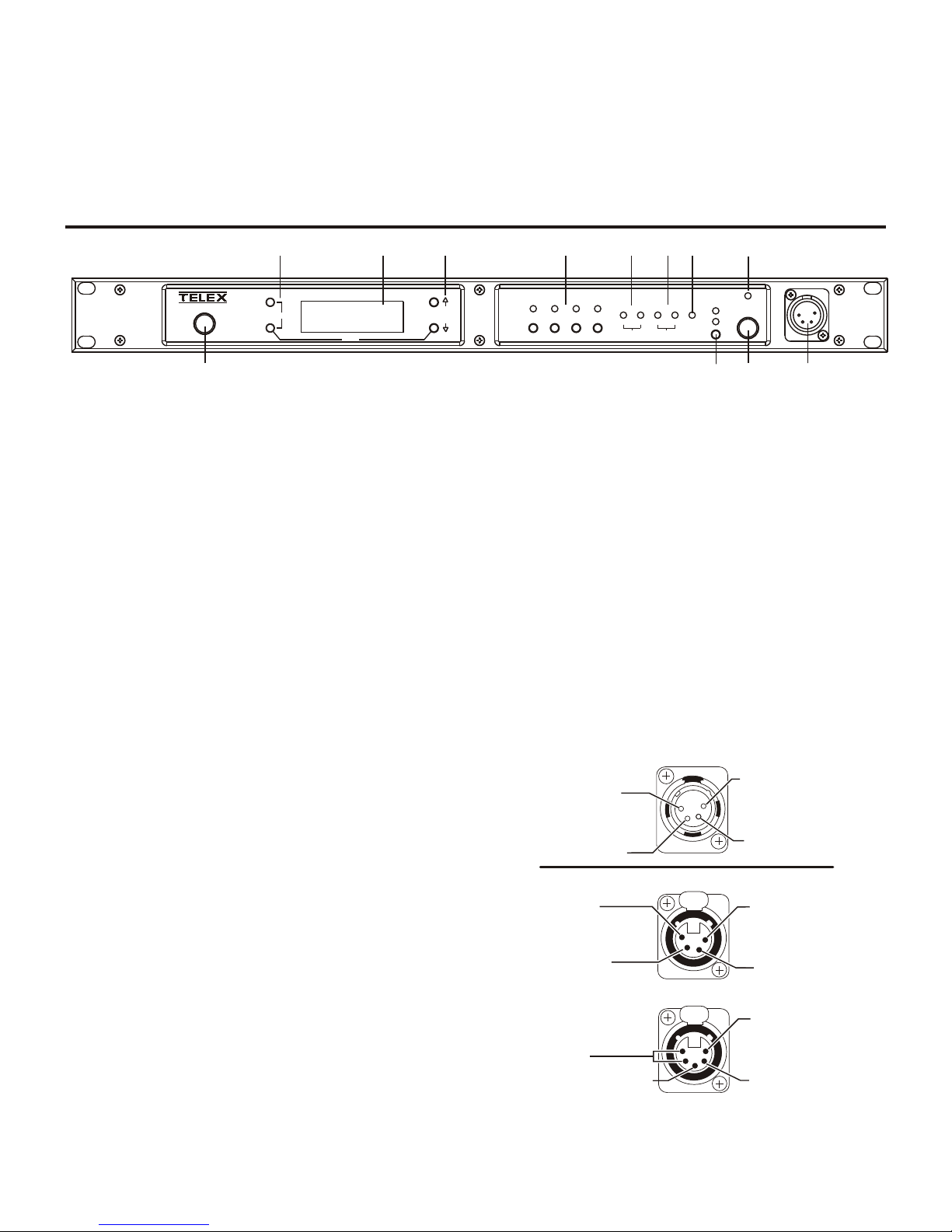
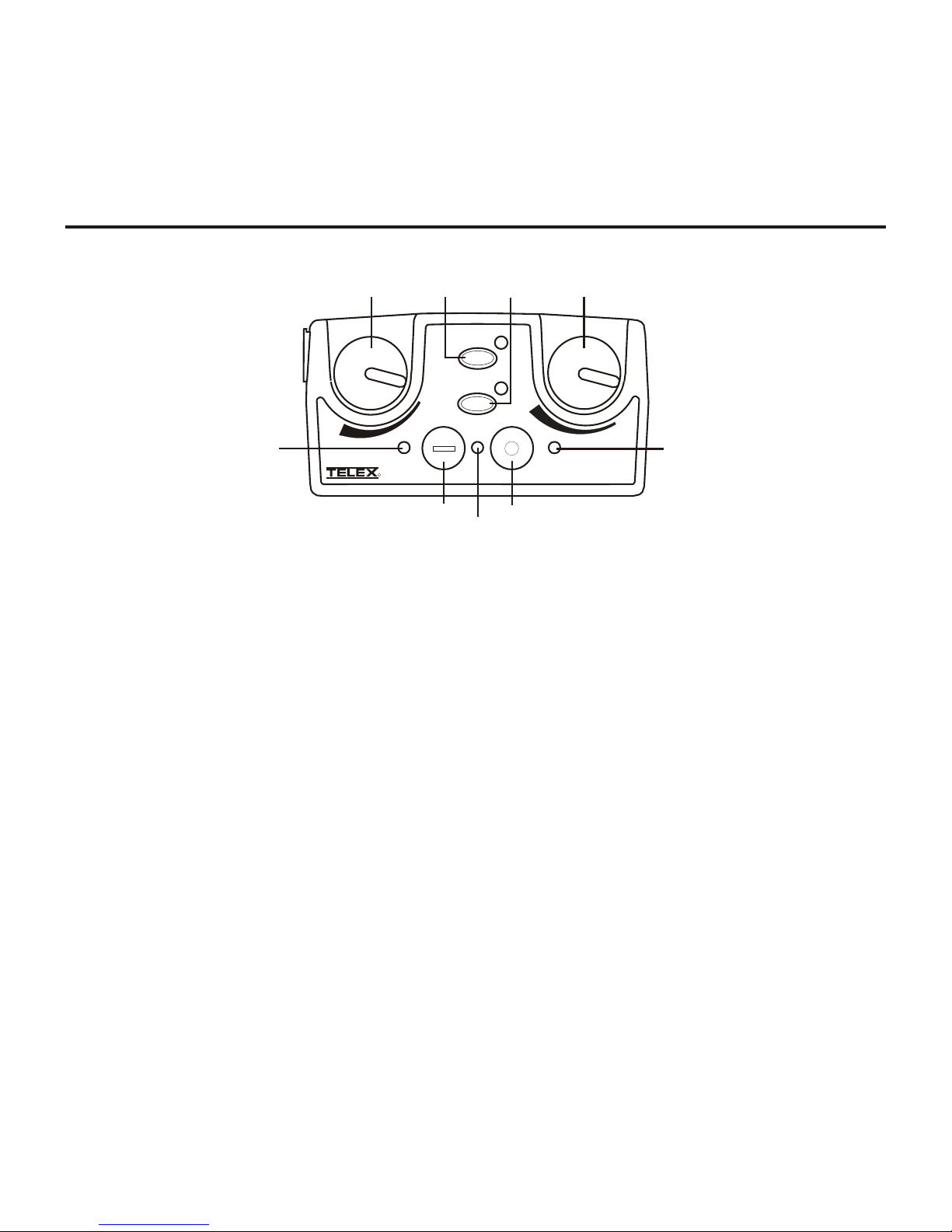
Fig ure 2-1
BTR-80N - Front Panel
.
1. Power switch – Do not power-up a base sta tion within 3
sec onds of the unit be ing turned off. Volt ages within the
unit need to drop be low a thresh old be fore be ing re-pow ered. If powerd-up in less than 3 sec onds, the unit may
boot as the wrong fre quency band.
2. [Menu] and [Set] but tons – Used to se lect menus and set
op tions on the LCD.
3. Backlit Graph ics LCD (Liq uid Crys tal Dis play).
4. [Up] and [Down] but tons – Used to se lect base sta tion
op tions on the LCD.
5. Por ta ble Sta tion Con nect – But tons used to en able or
dis able the re spec tive re ceiver’s au dio. GREEN LED =
Au dio en abled, LED OFF = Au dio dis abled.
Section
2
BTR-80N Base Sta tion
10. Talk/Peak Light – LED is green when talk but ton #11 is
ac tive. A nor mal mic gain set ting will cause the LED to
flash red on the loud est speech lev els. If the gain is too
high, the LED will be red at nor mal speech vol umes.
11. Talk But ton – Press to en able the au dio path from the lo cal
head set. LED #10 will turn green when en abled. A quick
press and re lease latches but ton on. If the talk func tion is
latched on, press ing the talk but ton again will turn it off.
12. Lo cal Head set Con nec tor – Male XLR con nec tor for Telex
units, Fe male XLR con nec tor for RTS units. A dy namic or
electret head set mi cro phone is au to mat i cally de tected. Mi cro phone gain and vol ume are settable in the soft ware
menus.
6. 4-wire Se lec tion/Peak In put In di ca tors - Displays when
4-wire in ter coms are ac tive with a gr een in di ca tion. A red
in di ca tion means the in ter com in put level is too high.
7. 2-Wire Se lec tion/Peak In put In di ca tors - Dis plays
which 2-wire in ter coms are ac tive with a gr een in di ca tion.
A red in di ca tion means the in ter com in put level is too
high.
8. Aux il iary Se lec tion/Peak In put in di ca tor - Dis plays if
aux il iary in put is 'ON" with a green in di ca tion. A red in di ca tion means the in ter com in put level is too high
9. Head set In ter com Se lect – Con trols the in ter com to
which the lo cal head set is con nected. Each press of the
but ton changes the con nec tion; chan nel 1, chan nel 2, both.
Fig ure 2-2
Lo cal Head set Wiring
2-1
Page 8

Con trols and Con nec tions - Rear Panel
RECEIVE
BTR-80N
RELAY
CONTACT
PROGRAM
BASE STATION
LINK
INTERCOM 1
2 WIRE
L
O
O
P
T
H
R
U
4 WIRE
INTERCOM 2
2 WIRE
L
O
O
P
T
H
R
U
4 WIRE
INPUT
OUTPUT
AUXILIARY
AUDIO
STAGE
ANNOUNCE
OUTPUT
12-15 VDC
3.5 A
MADE IN U.S.A.
100-240 VAC 50-60 Hz
Telex Communications, Inc.
2
T
R
A
N
S
M
I
T
1/2
1
4
5
6
7
8
11
2 3 9
10
IN
OUT
BTR-80N - Rear Panel
Fig ure 2-3
1. Re ceive An tenna - Fe male “TNC” Con nec tor. Color band
on an tenna must match color dot on base sta tion.
2. Re lay Con tact – A dry con tact clo sure which is ac ti vated
when a beltpack user presses the stage an nounce (SA) but ton. Nor mally Open (NO). The rat ing is one amp at 24V
max i mum.
3. Pro gram Con nec tor - Used to up date software in unit.
4. Base Sta tion Link Jacks – When multiple base sta tions
are con nected through this jack, it al lows wire less talk
around (WTA) au dio from the beltpacks to be routed from
sys tem to sys tem. Also will al low CAN bus data to be
passed be tween base sta tions.
5. In ter com 1 – In ter face to wired in ter com channel 1.
2-Wire – Male and fe male 3-pin XLR con nec tors
wired in par al lel. The con nec tors are switched to the
ap pro pri ate in ter com con fig u ra tion via soft ware.
4-Wire – An RJ-11 type jack com pat i ble with “Ma -
trix” type in ter com sys tems.
6. In ter com 2 – In ter face to wired in ter com channel 2.
2-Wire – Male and fe male 3-pin XLR con nec tors
wired in par al lel. The con nec tors are switched to the
ap pro pri ate in ter com con fig u ra tion via soft ware.
4-Wire – An RJ-11 type jack com pat i ble with “Ma -
trix” type in ter com sys tems.
7. Aux il iary In put/Out put – One 3-pin fe male XLR/ 1/4
inch com bi na tion in put con nec tor and one 3-pin male
XLR out put con nec tor.
8. Stage An nounce Out put – Passes the au dio from any of
the base sta tion’s beltpacks that have se lected stage an nounce (SA).
9. DC In put Jack – Ac cepts 12-15 VDC (5.5mm by 2.5mm
screw on plug), 3.5 Amps to power base sta tion from a
D.C. source. Base may be con nected to DC and AC source
at the same time. If AC source fails the base will au to mat i cally switch to D.C. power.
10. Power – IEC re cep ta cle. Ac cepts 100 – 240 VAC, 50 – 60 Hz.
11. Trans mit An tenna - Fe male “TNC” Con nec tor. Color
band on an tenna must match color dot on base sta tion.
2-2
Page 9

BTR-80N
Spec i fi ca tions
Over all
RF Fre quency Range ..............................482 - 608 MHz, 614 - 722 MHz, in 18 MHz TX and RX bands
(Some fre quen cies only avail able in cer tain coun tries)
Power Re quire ments ...............................................100-240 VAC, 50-60 Hz, IEC re cep ta cle
DC Only......................................................................12 - 15 VDC, 3.5 Amps
Tem per a ture Range ......................................................-4° F to 130° F (-20° C to 55° C)
Di men sions .....................................19.00” W x 1.72” H x 14.00” D (48.3 cm x 4.4 cm x 35.6 cm)
Weight ...........................................................................7 lbs 2 oz (3.24 kg)
TX An tenna .....................................................½ Wave (sup plied), TNC Male Con nec tor
RX An tenna.....................................................½ Wave (sup plied), TNC Male Con nec tor
FCC ID:.................................................................B5DM528 (TX 482-608 MHz)
Fre quency Re sponse .....................................................................200Hz-4kHz
Four Wire In put ........................................................Level Ad just able (2 Vrms typ i cal)
Four Wire Out put .......................................................Level Ad just able (2 Vrms typ i cal)
Telex In ter com ...........................In put/Out put Level Ad just able (1 Vrms typ i cal), Line im ped ance 300W
RTS In ter com.........................In put/Out put Level Ad just able (0.775 Vrms typ i cal), Line Im ped ance 200W
Clear-Com® In ter com ..................... In put/Out put Level Ad just able (1 Vrms typ i cal), Line Im ped ance 200W
Aux il iary In put..............................................................Ad just able (2 Vrms typ i cal)
Aux il iary Out put....................................................Ad just able (2 Vrms typ i cal into 600W)
Stage An nounce Out put........................In ter nally Ad just able (2 Vrms typ i cal at rated de vi a tion into 600W)
Stage An nounce Re lay ...............................................Dry con tact, rated at 1 Amp, 24V Max
Mi cro phone in put sen si tiv ity .....................................................................9mV
Lo cal Head set Out put ..............................................40mW out put into 600W (1% Dis tor tion)
Trans mit ter
Type.....................................................Two Syn the sized Trans mit ters, 720 chan nels each
Trans mit Power (each trans mit ter) ............................Selectable: off, 10 mW, 50 mW, 100 mW, 249 mW
Mod u la tion Type................................................................................FM
De vi a tion....................................................................................4 kHz
RF Fre quency Sta bil ity.......................................................................2.5 PPM
Mod u la tion Lim iter ........................................................Peak-Responding Com pres sor
Ra di ated Har monics & Spu ri ous ................................................Ex ceeds FCC spec i fi ca tions
Re ceiver
Type ................Tri ple Con ver sion Super het ero dyne, four In de pend ent Syn the sized IFs, FM, 720 chan nels each
RF Sen si tiv ity ...............................................................<0.6 µV for 12 dB SINAD
Squelch Thresh old ....................................................ad just able - 12 / 20 / 24 dB SINAD
IF Se lec tiv ity ................................................................6 dB at 30 kHz Bandwidth
Im age Re jec tion .......................................................................70 dB or better
Squelch Quieting..............................................................................90 dB
RF Fre quency Sta bil ity.......................................................................2.5 PPM
2-3
Page 10

2-4 Blank
Page 11
Con trols and Con nec tions - Top Panel
WTA
TALK
CHANNEL
BAT/PK TAL K
2
1
SA
OFF
VOL
R
1
2
4
5 6
7
3
Section
3
TR-80N Beltpack
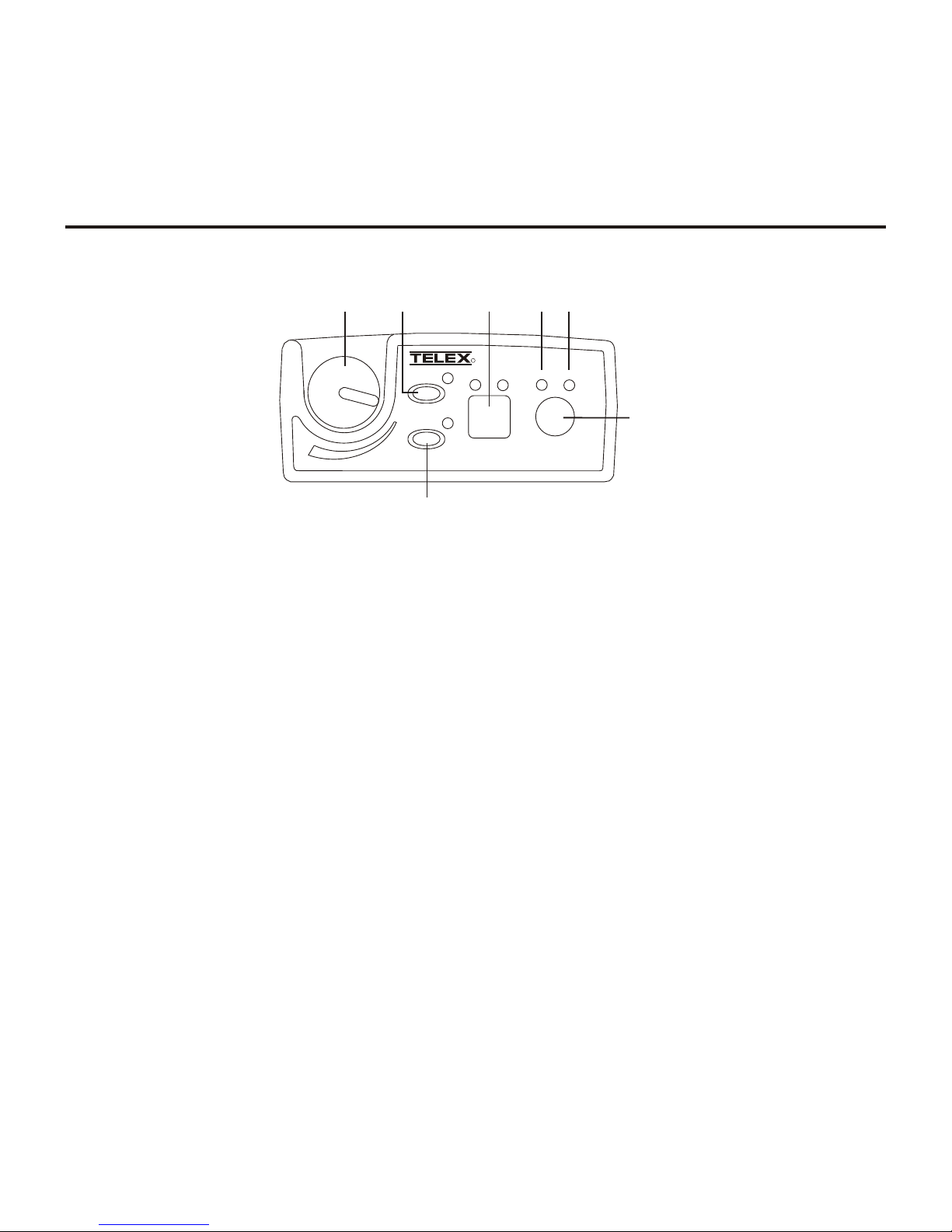
Fig ure 3-1
TR-80N Top Panel
1. On/Off & Vol ume Con trol – Turns the beltpack power
on and con trols head set vol ume.
2. Wire less Talk Around ( WTA) – When pressed, the user’s
au dio is dis con nected from the wired in ter com, aux il iary
in put/out put and the base sta tion’s lo cal head set. Other
beltpack us ers, on that au dio chan nel, can hear the user as
nor mal. The but ton ac ti vates the nearby red LED as well
as the talk but ton.
3. Stage An nounce (SA) –When pressed, the user’s au dio is
routed to the stage an nounce con nec tor on the back of the
base sta tion. The user also loses their sidetone as an in di ca tion that stage an nounce is ac ti vated. Th e other wire less
beltpacks and wired us ers do not hear the user’s au dio.
The but ton is non-latching and ac tivates the nearby red
LED as well as the talk but ton.
4. Au dio Chan nel Se lect Button – A l low s user to se lect ei -
ther au dio chan nel 1or 2.
5. Bat/Peak Light (BAT/PK) – Light will flash once when
unit is turned on if the bat tery is good. If the light stays on,
bat tery is low. If the light does not flash, bat tery is d ead. A
nor mal mi cro phone gain set ting will cause the LED to
flash for some of the words at nor mal speech lev els. If the
gain is too high, the LED will be red dur ing all words at
nor mal speech lev els.
6. Talk Light – LED is on when the talk but ton, SA or WTA
is ac tive.
7. Talk but ton – Press to en able the au dio path from the lo -
cal head set mi cro phone. The “TALK” LED, #6, will turn
red when en abled. A quick press and re lease latches the
talk func tion, un less latch ing has been dis abled. Holding
the but ton for over ½ a sec ond will cause the au dio path to
be en abled only for as long as the but ton is held. If the talk
func tion is latched on, press ing the talk but ton again will
turn it off.
3-1
Page 12
Con trols and Con nec tions - Rear Panel
MENU
SET
5
6
7
8
MENU
SET
2
1
3
4
(1) Microphone
Shield (-)
(2) Microphone
Audio (+)
(4) Headphone
Low (-)
(3) Headphone
High (+)
Telex Units
(1) Microphone
Shield (-)
(4) Headphone
Low (-)
(3) Headphone
High (+)
(2) Microphone
Audio (+)
(1) Microphone
Shield (-)
(5) (4) Headphone Low (-)
(3) Headphone High (+)
(2) Microphone
Audio (+)
RTS Units
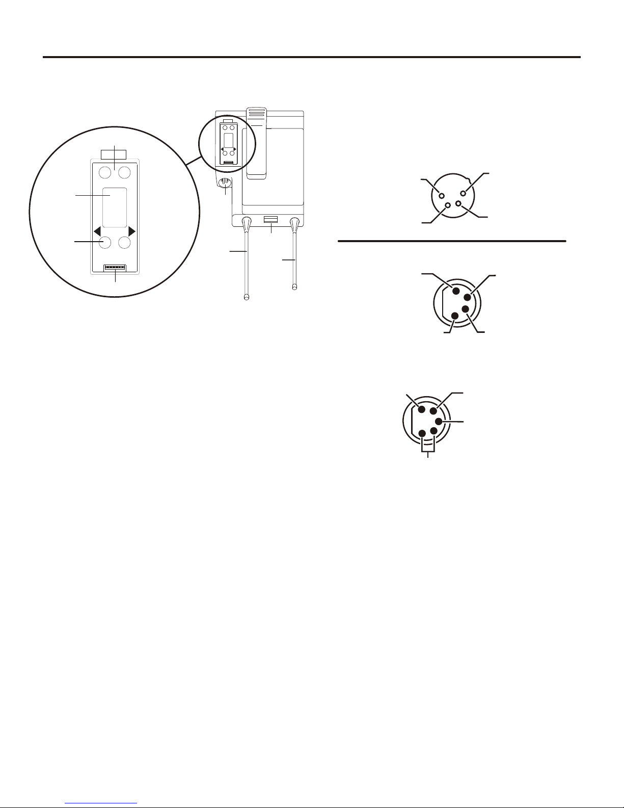
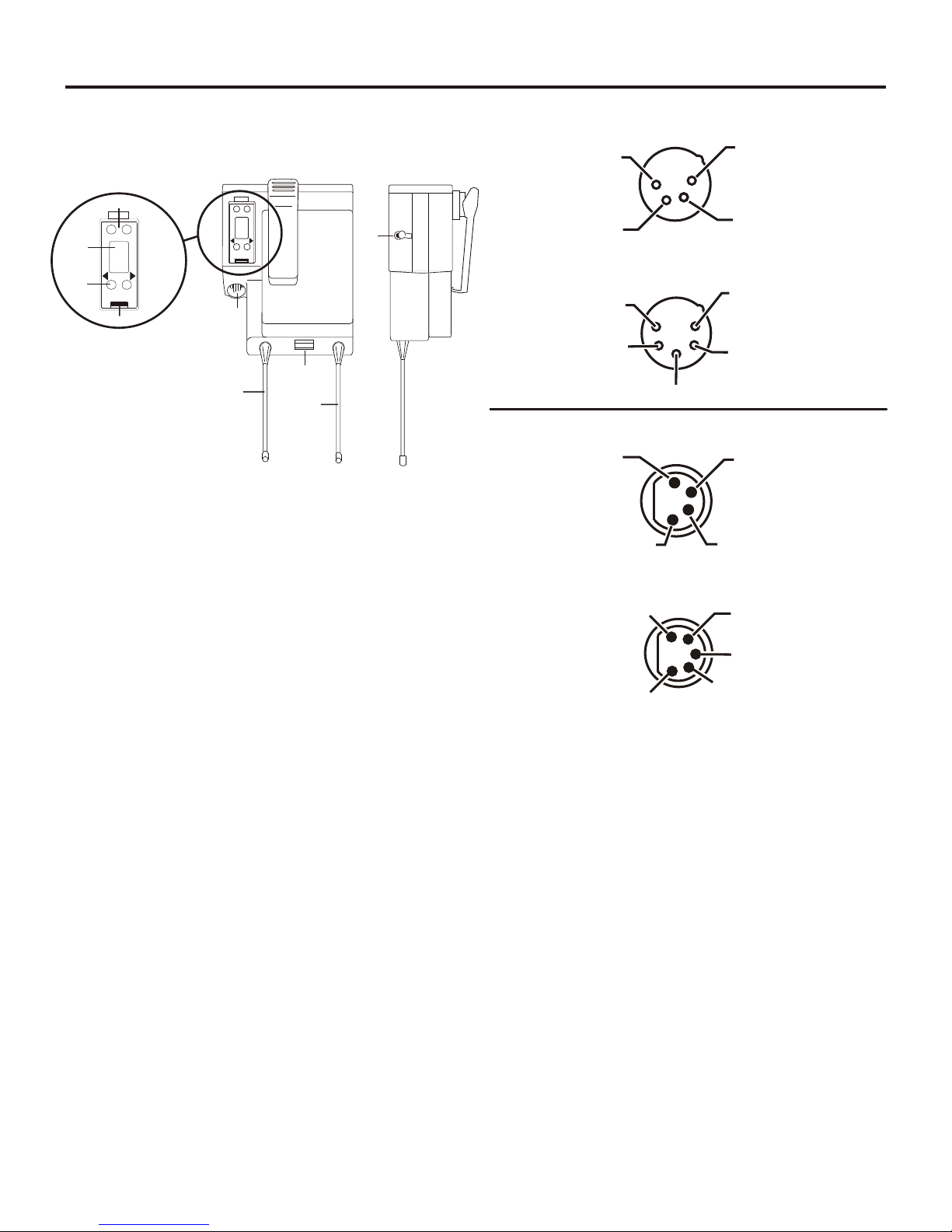
5. Head set Con nec tor – Male XLR con nec tor for Telex
units, Fe male XLR con nec tor for RTS units. A dy namic or
electret head set mi cro phone is au to mat i cally de tected by
the beltpack and a bias volt age sup plied if needed.
Fig ure 3-2
TR-80N Rear Panel/Con nec tor/An tennas
1. [MENU] and [SET] but tons – Used to se lect menus and
set op tions on the LCD.
2. LCD (Liq uid Crys tal Dis play)
3. [UP] and [DOWN] but tons – Used to se lect beltpack op -
tions on the LCD.
4. Pro gram ming Con nec tor – Used to up date soft ware in
unit.
Fig ure 3-3
Head set Jack Wir ing
6. Bat tery Latch – Press down to release the bat tery pack.
While hold ing the latch down, slide the bat tery pack about
1/8 inch back to ward the latch, un til it stops, then lift it
out.
7. Re ceive An tenna – Screw type ¼-wave re place able an -
tenna. The color dot on the screw end of the an tenna must
match color dot on an tenna re cep ta cle.
8. Trans mit An tenna – Screw type ¼-wave re place able an -
tenna. Color dot on the screw end of the an tenna must
match color dot on an tenna re cep ta cle.
NOTE: Mi cro phone gain and trans mit mode is set
via soft ware menus.
3-2
Page 13

TR-80N
Spec i fi ca tions
RF Fre quency Range ..............................482 - 608 MHz, 614 - 722 MHz, i n 18 MHz TX and R X bands
(Some fre quen cies only avail able in cer tain coun tries)
Power Re quire ments................................................6 “AA” Cells Al ka line (NiMH op tional)
Cur rent Draw ...........................................................200 mA (Push-to-Talk, Talk On)
Tem per a ture Range ......................................................-4° F to 130° F (-20° C to 55° C)
Di men sions .........................................3.75”W x 5.05”H x 1.65” D (9.5 cm x 12.8 cm x 4.2 cm)
Weight ..............................................................16 oz (454g) with al ka line bat ter ies
TX An tenna..................................................1/4 Wave (sup plied), Screw type, Re place able
RX An tenna .................................................1/4 Wave (sup plied), Screw type, Re place able
FCC ID:.................................................................B5DM530 (TX 608-698 MHz)
Fre quency Re sponse .....................................................................200Hz-4kHz
Mi cro phone in put sen si tiv ity.....................................................................7 mV
Lo cal Head set Out put ..............................................40 mW out put into 600W (1% dis tor tion)
Trans mit ter
Type .......................................................................Syn the sized, 720 chan nels
Trans mit Power .........................................................Selectable: Auto, 5, 50, 100 mW
Mod u la tion Type................................................................................FM
De vi a tion....................................................................................4 kHz
RF Fre quency Sta bil ity.......................................................................2.5 PPM
Mod u la tion Lim iter ........................................................Peak-Responding Com pres sor
Ra di ated Har monics & Spu ri ous ................................................Ex ceeds FCC spec i fi ca tions
Type .....................................Tri ple Con ver sion Super het ero dyne, Syn the sized, FM, 720 chan nels
RF Sen si tiv ity ...............................................................<0.6 µV for 12 dB SINAD
Squelch Thresh old ........................................ad just able - 12 / 20 / 24 dB SINAD (About 1.0 mV)
IF Se lec tiv ity ................................................................6 dB at 30 kHz Bandwidth
Im age Re jec tion .......................................................................70 dB or better
Squelch Quieting..............................................................................90 dB
RF Fre quency Sta bil ity.......................................................................2.5 PPM
Re ceiver
3-3
Page 14

3-4 Blank
Page 15
Con trols and Con nec tions - Top Panel
TALK
TAL K
VOL
VOL
OFF
OFF
WTA
SA
BAT/
PK
R
1 2
1
2
3 1
6
6
4 4
5
Section
4
TR-82N Beltpack
Fig ure 4-1
TR-82N Top Panel
1. On/Off and Vol ume Con trol - Turns beltpack power on
and con trols head set vol ume for in ter com chan nels “1”
and “2”. Ei ther knob, “1” or “2”, turns the beltpack on.
Both knobs must be off to turn the beltpack off. If only
one knob is on, then that in ter com channel, “1” or “2” is
on for both trans mit and re ceive au dio.
2. Wire less Talk Around (WTA) - When pressed, the user ’s
au dio is dis con nected from the wired in ter com, aux il iary
in put/out put and the base sta tion’s lo cal head set. Other
beltpack us ers, on that au dio chan nel, can hear the user as
nor mal. The de fault set ting is soft ware selectable, as to
which in ter com chan nels, “1”, “2”, “1 + 2”, or cur rently
se lected chan nel, is ac ti vated along with the “WTA” but ton. The “WTA” but ton ac ti vates the nearby red LED as
well as the soft ware se lected in ter com chan nels “TALK”
LED if not al ready ac tive.
3. Stage An nounce (SA) - When pressed, the user’s au dio is
routed to the stage an nounce con nec tor on the back of the
base sta tion. The user also loses their sidetone as an in di ca tion that stage an nounce is ac ti vated. Th e other wire less
beltpacks and wired us ers do not hear the user’s au dio.
The but ton is non-latching and ac ti vates the nearby red
LED.
4. Talk But ton - Press to en able the au dio path to ei ther in -
ter com chan nels “1”, “2” or “1 + 2”, from the lo cal head set mi cro phone. The as so ci ated “TALK” LED, #6, will
turn red when en abled. A quick press and re lease latches
the talk func tion, un less latch ing has been dis abled.
Holding the but ton for over ½ sec ond will cause the au dio
path to be en abled only for as long as the but ton is held. If
the talk func tion is latched on, press ing the talk but ton
again will turn it off.
5. Low Bat tery/Peak (BAT/PK) Light - Light will flash
once when unit is turned on if the bat tery is good. If the
light stays on, bat tery is low. If the light does not flash,
bat tery is dead. A nor mal mi cro phone gain set ting will
cause the LED to flash for some words at nor mal speech
lev els. If the gain is too high, the LED will be red dur ing
all words at nor mal speech lev els.
6. Talk Light - Will turn red when en abled by as so ci ated
“TALK” or “WTA” but ton.
4-1
Page 16
Con trols and Con nec tions - Rear Panel
MENU
SET
6
7
8
9
MENU
SET
2
1
3
4
5
SIDE VIEW
(1) Microphone
Shield (-)
(3) Switched
Headphone Ground
(2) Microphone
Audio (+)
(4) Headphone
(Audio A)
(5) Headphone
(Audio B)
(1) Microphone
Shield (-)
(4) Headphone
Low (-)
(3) Headphone
High (+)
(2) Microphone
Audio (+)
(1) Microphone
Shield (-)
(2) Microphone
Audio (+)
(5) Headphone
Audio B
(4) Headphone
Audio A
(3) Switched Headphone Ground
(1) Microphone
Shield (-)
(2) Microphone
Audio (+)
(4) Headphone
Low (-)
(3) Headphone
High (+)
Telex Units
RTS Units
Fig ure 4-2
TR-82N Rear Panel/Con nec tor/An tennas
1. [MENU] and [SET] but tons – Used to se lect menus and
set op tions on the LCD.
2. LCD (Liq uid Crys tal Dis play)
3. [UP] and [DOWN] but tons – Used to se lect beltpack op -
tions on the LCD.
4. Pro gram ming Con nec tor - Used to up date soft ware in
unit.
5. Aux il iary In put Au dio Jack -1/8" (3.5mm) mono in put
jack. Lo cal only to beltpack.
6. Head set Con nec tor – Male XLR con nec tor for Telex
units, Fe male XLR con nec tor for RTS units. A dy namic or
electret head set mi cro phone is au to mat i cally de tected by
the beltpack and a bias volt age sup plied if needed. Four
pin Telex/RTS units are mon au ral. Five pin Telex/RTS
units have a soft ware set-up to se lect if XLR pin 3 or 5 is
the chan nel 2 out put and if pin 3 is ground.
Fig ure 4-3
Head set Jack Wir ing
7. Bat tery Latch – Press down to release the bat tery pack.
While the latch is held down, slide the bat tery pack about
1/8 inch back, to ward the latch, un til it stops, then lif t it
out.
8. Re ceive An tenna – Screw type ¼-wave re place able an -
tenna. The color dot on the screw end of the an tenna must
match color dot on an tenna re cep ta cle.
9. Trans mit An tenna – Screw type ¼-wave re place able an -
tenna. The color dot on the screw end of the an tenna must
match color dot on an tenna re cep ta cle.
NOTE: Mi cro phone gain and trans mit mode is set via
soft ware menus.
4-2
Page 17

TR-82N
Spec i fi ca tions
RF Fre quency Range ...............................482 - 608 MHz, 614 - 722 MHz, in 18 MHz TX and RX bands
(Some fre quen cies only avail able in cer tain coun tries)
Power Re quire ments................................................6 “AA” Cells Al ka line (NiMH op tional)
Cur rent Draw ....................................................280 mA (Push-to-Talk, A and B Talk On)
Tem per a ture Range ......................................................-4° F to 130° F (-20° C to 55° C)
Di men sions ........................................3.75” W x 5.35” H x 2.02” D (9.5 cm x 13.5 cm x 5.1 cm)
Weight ..............................................................21 oz (595g) with al ka line bat ter ies
TX An tenna..................................................1/4 Wave (sup plied), Screw type, Re place able
RX An tenna .................................................1/4 Wave (sup plied), Screw type, Re place able
FCC ID:.................................................................B5DM531 (TX 608-698 MHz)
Fre quency Re sponse .....................................................................200Hz-4kHz
Mi cro phone in put sen si tiv ity.....................................................................7 mV
Lo cal Head set Out put..............................................40 mW out put into 600W (1% dis tor tion)
Trans mit ter
Type .......................................................................Syn the sized, 720 chan nels
Trans mit Power .........................................................Selectable: Auto, 5, 50, 100 mW
Mod u la tion Type................................................................................FM
De vi a tion ................................................................................... 4 kHz
RF Fre quency Sta bil ity.......................................................................2.5 PPM
Mod u la tion Lim iter ........................................................Peak-Responding Com pres sor
Ra di ated Har monics & Spu ri ous ................................................Ex ceeds FCC spec i fi ca tions
Re ceiver
Type......................... Two, Triple Con ver sion Super het ero dyne Receivers, Syn the sized, FM, 720 chan nels
RF Sen si tiv ity ...............................................................<0.6 µV for 12 dB SINAD
Squelch Thresh old ......................................................ad just able - 12 /20 /24 dB SINAD
IF Se lec tiv ity ................................................................6 dB at 30 kHz Bandwidth
Im age Re jec tion .......................................................................70 dB or better
Squelch Quieting..............................................................................90 dB
RF Fre quency Sta bil ity.......................................................................2.5 PPM
4-3
Page 18

4-4 Blank
Page 19

Un packing
Section
5
Ini tial Equip ment Set-Up
Un pack your RadioCom™ Sys tem. Be low are the items that
should come with your base sta tion and each belt pack.
Quan tity De scrip tion
BTR-80N
1 BTR-80N Base Sta tion
1 Op er ating In struc tions
1 Power Cord
2 An tennas (one Trans mit and one Re ceive)
1 War ranty Card
1 2 ter mi nal plug (for SA Re lay)
4 Rub ber feet
Quan tity De scrip tion
Con tact the ship per or your dealer im me di ately if any thing is
dam aged or miss ing.
TR-80N,
TR-82N
1 TR-80N or TR-82N with An tennas
1 Bat tery pack
1 Quick Start Card
1 War ranty Card
1 Belt Clip
1 LCD Cover
5-1
Page 20
An tenna Con nec tion
2
1/
2
T
R
A
N
S
M
I
T
POWER
MENU
ClearScan
SET
COPY
BTR-80N
UP
DOWN
1 2 3 4
PORTABLE STATION CONNECT
INPUTS
4 WIRE 2 WIRE
1 2
21
AUX
CHANNEL
SELECT
1
2
ON/O.M.
TALK
W
T
A
A
B
O
F
F
B
A
T
/
O
M
T
A
L
K
VOL
SA
R
TR-80N
W
T
A
A
B
O
F
F
B
A
T
/
O
M
T
A
L
K
VOL
SA
R
TR-80N
R
The base sta tion is sup plied with two (2) an ten nas. One
1/2-wave an tenna for Trans mit and one 1/2-wave for Re ceive.
The an ten nas have TNC male con nec tors.
The fre quency range of the an ten nas should match the re ceiver
and trans mit ter of the base sta tion. Match the color code on
the an tenna with the color code on the base sta tion.
At tach the trans mit 1/2-wave an tenna to the an tenna in put re --
cep ta cle la beled “Trans mit” on the right side of the rear panel.
The an tenna should be ver ti cally aligned.
Fig ure 5-1
Attaching Trans mit 1/2-Wave An tenna
At tach the re ceive 1/2-wave an tenna to the an tenna in put re --
cep ta cle la beled “Re ceive” on the left side of the rear panel.
The an tenna should be ver ti cally aligned.
ANTENNAS SHOULD BE VERTICAL
Fig ure 5-3
Ver ti cally Po lar ized An tennas
Dis tance be tween An tennas
The dis tance be tween the base sta tion’s re ceive and tr ans mit
an ten nas is not ad just able when the an ten nas are con nected di --
rectly on the back of the unit.
The an ten nas can be remotely mounted for a better sig nal
path. A Telex coax as sem bly with re mote an ten nas may be re --
quired. See "Ac ces sory" sec tion for or der ing information.
NOTE: If your base sta tion is to be lo cated in a shielded rack
mount en clo sure or other poor RF lo ca tion, you must re motely
mount the 1/2-wave an ten nas with coax as sem blies. See "Ac --
ces sories and Re place ment Parts" sec tion for re mote mount ing
hard ware.
An tenna Place ment
Proper an tenna place ment prob a bly has the most ef fect on
your TELEX Wire less In ter com Sys tem’s over all per for --
mance. The fol low ing sug ges tions will re sult in op ti mum per --
for mance.
Fig ure 5-2
Attaching Re ceive 1/2-Wave An tenna
An tenna Po lar iza tion
The Telex Wire less In ter com Sys tem is “Ver ti cally Po lar ized”.
This means both the trans mit ting and re ceiv ing an ten nas
should op er ate in the ver ti cal po si tion.
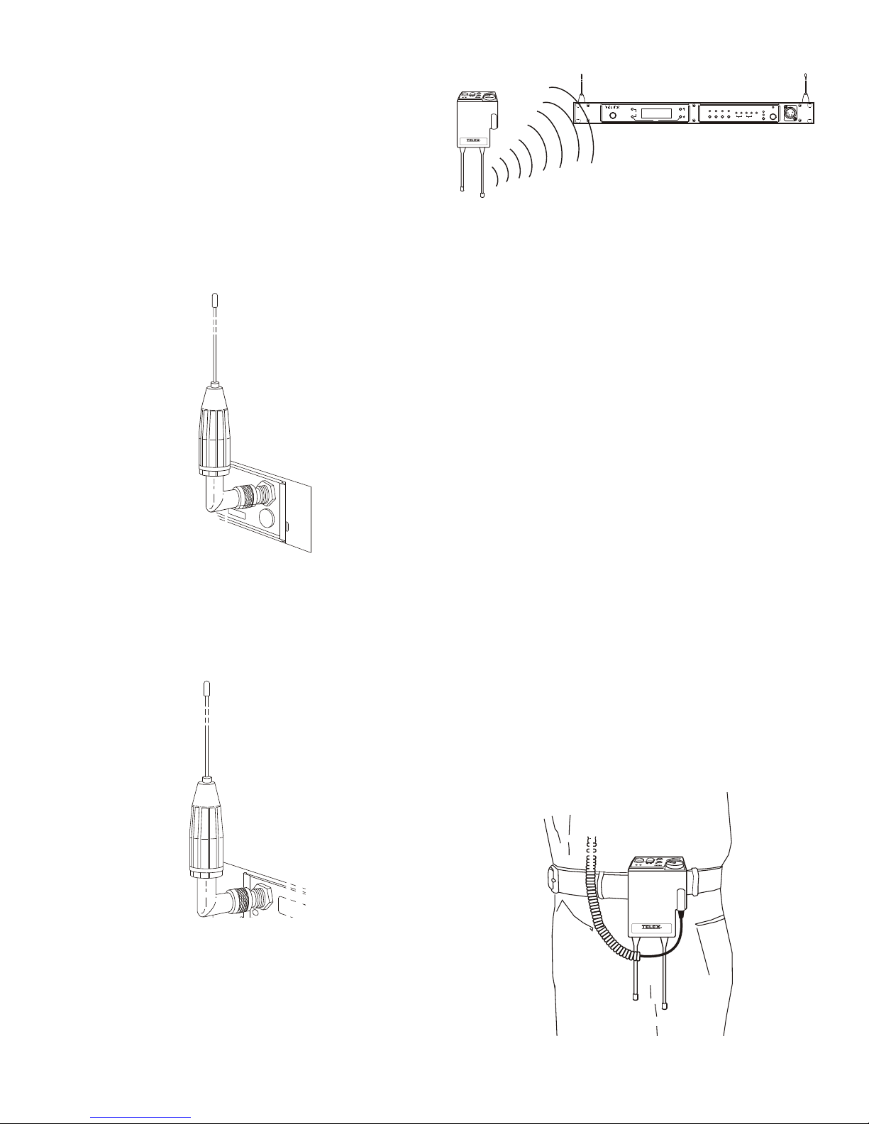
Proper place ment of the beltpack can be crit i cal. The an ten nas
should be in the open. Bending the an ten nas up and plac ing
the beltpack in a pocket, etc., will re duce sys tem dis tance.
It is sug gested that the unit be worn on the belt or pocket with
both an tennas ver ti cal for best op er at ing range and per for --
mance.
Fig ure 5-4
Proper Dress ing of the An tennas
5-2
Page 21
Keep the dis tance be tween the base sta tion and the beltpacks
POWER
MENU
ClearScan
SET
COPY
BTR-80N
UP
DOWN
1 2 3 4
PORTABLE STATION CONNECT
INPUTS
4 WIRE 2 WIRE
1 2
21
AUX
CHANNEL
SELECT
1
2
ON/O.M.
TALK
W
T
A
A
B
O
F
F
B
A
T
/
O
M
T
A
L
K
VOL
SA
R
TR-80N
W
T
A
A
B
O
F
F
B
A
T
/
O
M
T
A
L
K
VOL
SA
R
TR-80N
100 FEET
70 FEET
POWER
MENU
ClearScan
SET
COPY
BTR-80N
UP
DOWN
1 2 3 4
PORTABLE STATION CONNECT
INPUTS
4 WIRE 2 WIRE
1 2
21
AUX
CHANNEL
SELECT
1
2
ON/O.M.
TALK
W
T
A
A
B
O
F
F
B
A
T
/
O
M
T
A
L
K
VOL
SA
R
TR-80N
W
T
A
A
B
O
F
F
B
A
T
/
O
M
T
A
L
K
VOL
SA
R
TR-80N
POWER
MENU
ClearScan
SET
COPY
BTR-80N
UP
DOWN
1 2 3 4
PORTABLE STATION CONNECT
INPUTS
4 WIRE 2 WIRE
1 2
21
AUX
CHANNEL
SELECT
1
2
ON/O.M.
TALK
W
T
A
A
B
O
F
F
B
A
T
/
O
M
T
A
L
K
VOL
SA
R
TR-80N
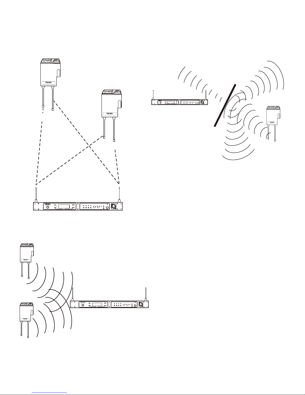
as short as pos si ble. The greater the dis tance, the weaker the
sig nal. Make sure the “sig nal paths” be tween the base sta tion
and beltpacks are un ob structed. You should be able to vis i bly
lo cate the base sta tion an ten nas at all times for best per for --
mance.
At tempting to op er ate the wire less in ter com sys tem through or
around walls, ceil ings, metal ob jects, etc. will re duce sys tem
range and per for mance.
Fig ure 5-7
Op er ating Sys tem Near Ob struc tions
DO NOT - mount the base sta tion 1/2-wave an ten nas on, or
next to metal, such as beams, walls with metal studs , equip --
ment racks, etc. This also ap plies to the an ten nas when as sem --
bled di rectly to the Base Sta tion. This will “de tune” the
Fig ure 5-5
Dis tance Be tween base sta tion and beltpack
an ten nas which can re sult in noise or loss of RF sig nal at the
Base Sta tion, see Fig ure 5-8.
Fig ure 5-6
Keeping Site Clear to An tenna
5-3
Page 22
T
elex
UHF ANTENNA SPLITTER/COMBINER
SC - 600
T
elex
R
T
elex
T
elex
UHF ANTENNA SPLITTER/COMBINER
SC - 600
T
elex
R
#1
#2
#3
POWER
MENU
ClearScan
SET
COPY
BTR-80N
UP
DOWN
1 2 3 4
PORTABLE STATION CONNECT
INPUTS
4 WIRE 2 WIRE
1 2
21
AUX
CHANNEL
SELECT
1
2
ON/O.M.
TALK
POWER
MENU
ClearScan
SET
COPY
BTR-80N
UP
DOWN
1 2 3 4
PORTABLE STATION CONNECT
INPUTS
4 WIRE 2 WIRE
1 2
21
AUX
CHANNEL
SELECT
1
2
ON/O.M.
TALK
POWER
MENU
ClearScan
SET
COPY
BTR-80N
UP
DOWN
1 2 3 4
PORTABLE STATION CONNECT
INPUTS
4 WIRE 2 WIRE
1 2
21
AUX
CHANNEL
SELECT
1
2
ON/O.M.
TALK
POWER
MENU
ClearScan
SET
COPY
BTR-80N
UP
DOWN
1 2 3 4
PORTABLE STATION CONNECT
INPUTS
4 WIRE 2 WIRE
1 2
21
AUX
CHANNEL
SELECT
1
2
ON/O.M.
TALK
POWER
MENU
ClearScan
SET
COPY
BTR-80N
UP
DOWN
1 2 3 4
PORTABLE STATION CONNECT
INPUTS
4 WIRE 2 WIRE
1 2
21
AUX
CHANNEL
SELECT
1
2
ON/O.M.
TALK
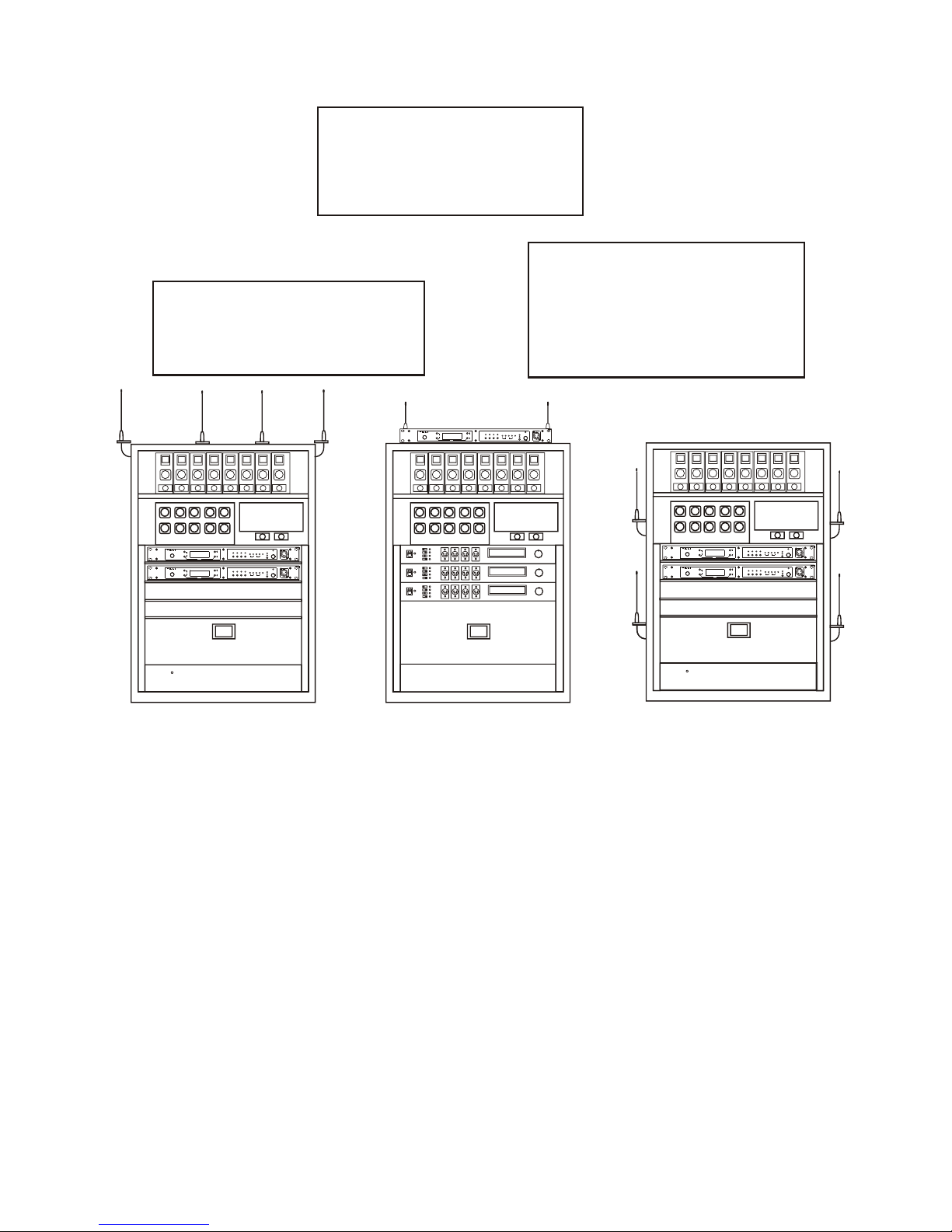
2. Placing the BTR on top of a
shelf or equip ment rack un ob structed with out remoting
the an ten nas is OK.
1. Placing BTRs in a shelf or
equip ment rack and us ing re mote an ten nas is OK.
3. Placing BTRs in a shelf or
equip ment rack with the an ten nas mounted on the back
of the BTR or the side of the
rack is BAD.
Im proving Re cep tion and In creasing
Range
Keeping the dis tance from the base sta tion and beltpack as
short, and un ob structed as pos si ble will pro duce the most re li --
able per for mance.
Fig ure 5-8
An tenna Place ment
The base sta tion is sup plied with two an ten nas. This should
pro vide sat is fac tory sys tem per for mance in most ap pli ca tions.
Sys tem range can be en hanced by re motely mounting the
1/2-wave an ten nas. The ½ wave an ten nas are ground plane in --
de pend ent, so a ground plane is not re quired for good per for --
mance.
5-4
Page 23

5-5 Blank
Page 24

Sec tion
6
BTR-80N Op er a tion
BTR-80N Op er a tion
This Sec tion will dis cuss the op er a tion and fea tures of the
BTR-80N base sta tion. The sec tion will open with the base
op er a tion and quick sys tem setup of a BTR-80N sys tem. It
will then dis cuss ba sic in ter fac ing and setup of a base sta tion.
Fi nally it will end with the con nec tion of mul ti ple base sta --
tions and dis cus sion of the links be tween them.
Ba sic Op er a tional De scrip tion
The BTR-80N nar row band wire less in ter com sys tem of fers the
most com pre hen sive, user friendly and ver sa tile set of fea tures
avail able in wire less in ter com sys tems any where in the world.
The base station can ac com mo date up to 4 full du plex TR-80N
or TR-82N beltpacks. A base may be used with an un lim ited
num ber of beltpacks in push-to-TX (half du plex) op er a tion. In
push-to-TX mode the unit pro vides a "First-On-Latch-Out"
fea ture. This fea ture al lows only one beltpack trans mit ter ac --
tive at a time when mul ti ple us ers are on a sin gle base re ceive
chan nel.
The base sta tion, via the beltpacks or it's lo cal head set, al lows
com mu ni ca tion with other wire less or wired us ers. The 2-wire
and 4-wire in ter coms may even be used at the same time. The
wired au dio in ter faces to the base are:
2-Wire (Telex, RTS, Clear-Com) - 2 in ter com chan nels
•
for the user to en ter fre quen cies of their own via 12 user de --
fined groups.
Sys tem Quick Start
The fol low ing is a list to quickly get a base sta tion and
beltpacks op er at ing.
1. Un pack the base and con nect the power cord and an ten nas.
2. Connect base to au dio in ter faces. For ex am ple; 2-wire,
4-wire, SA, Aux il iary local head set.
3. Press and hold [MENU] as pow er ing-up the base sta tion. Re lease but ton when base sta tion dis plays
"...FAC TORY SETUP...".
4. Press [MENU] as pow er ing-up the beltpacks(s)
5. Use the [UP] and [DOWN] ar row but ton to change the
chan nel to an un oc cu pied re ceive chan nel on the base sta tion. Then press [SET] twice to set chan nel and group.
6. The base should now dis play the au dio chan nel of the
beltpack and a bat tery sym bol will ap pear shortly.
7. Plug a head set into each beltpack. Ad just the soft ware
menu for mi cro phone gain so the overmodulation light
flashes only on some of the words at nor mal speech
lev els.
4-Wire - 2 au dio chan nels
•
Aux il iary (both in put and out put)
•
SA (Stage An nounce) (out put)
•
WTA (Wire less Talk Around). 2 chan nels of a pri vate
•
2-wire in ter com just among TR-80N and TR-82N
beltpacks.
Lo cal base sta tion head set
•
The base also has a re lay clo sure avail able that is ac ti vated
when the SA is pressed at any beltpack. There are 4 eas ily ac --
ces si ble por ta ble con nect but tons on the front panel. The but --
tons may be used to turn off the au dio from any of the four
base re ceiv ers while at the same time kill ing the talk/trans mit --
ter at the as so ci ated beltpack.
The base sta tion co mes with 36 en gi neer ing se lected,
intermodulation-avoid ing groups of chan nels, plus the abil ity
6-1
Page 25
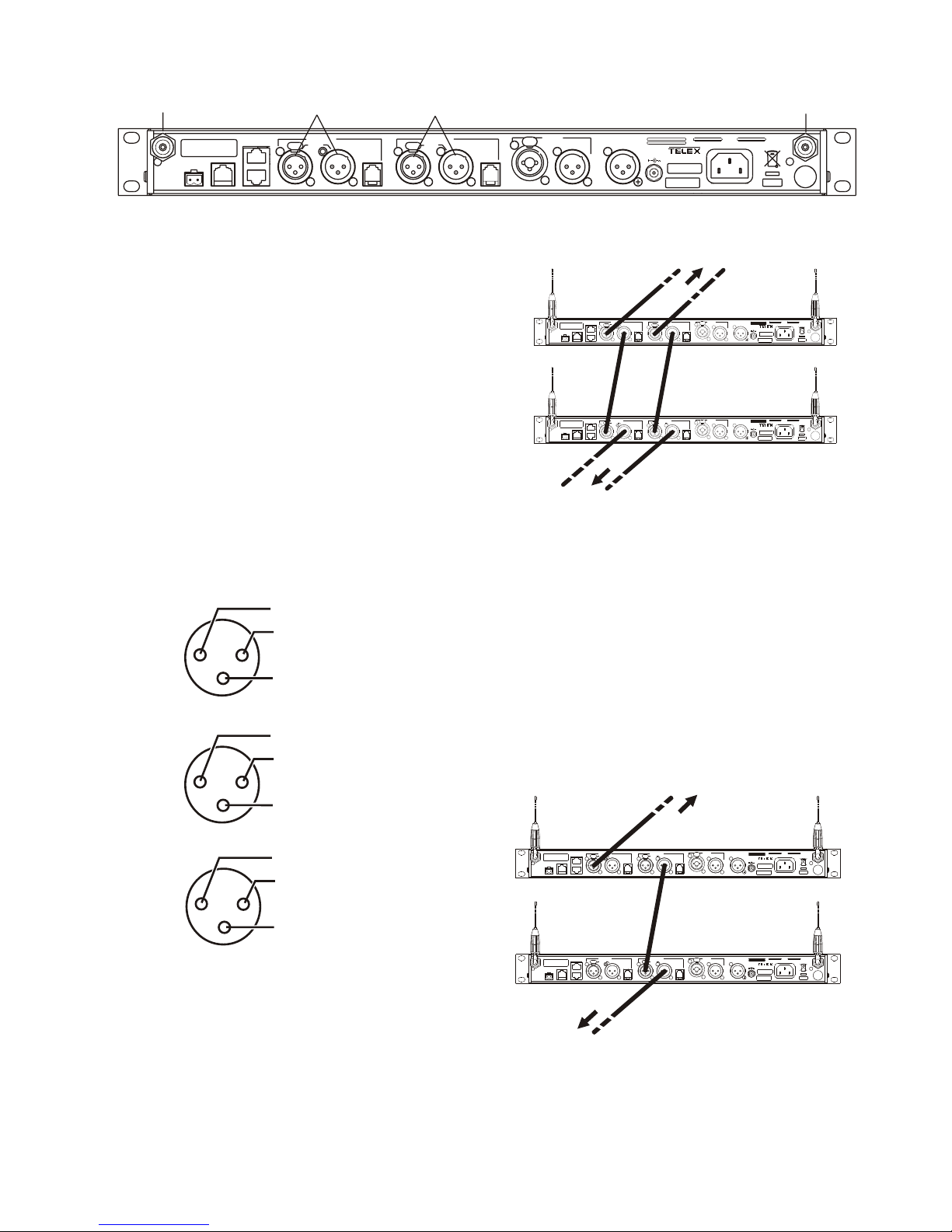
Fig ure 6-1
RECEIVE
BTR-80N
RELAY
CONTACT
PROGRAM
BASE STATION
LINK
INTERCOM 1
2 WIRE
L
O
O
P
T
H
R
U
4 WIRE
INTERCOM 2
2 WIRE
L
O
O
P
T
H
R
U
4 WIRE
INPUT
OUTPUT
AUXILIARY
AUDIO
STAGE
ANNOUNCE
OUTPUT
12-15 VDC
3.5 A
MADE IN U.S.A.
100-240 VAC 50-60 Hz
Telex Communications, Inc.
2
T
R
A
N
S
M
I
T
1/2
IN
OUT
RECEIVE
JACK
2-WIRE
INTERCOM
PORT
TRANSMIT
JACK
2-WIRE
INTERCOM
PORT
COMMON
1
2
3
AUDIO 1 PLUS POWER
AUDIO 2
RTS
COMMON
1
2
3
AUDIO (-) PLUS POWER
AUDIO (+) PLUS POWER
Telex/
AudioCom
COMMON
1
2
3
POWER
AUDIO
Clear-Com
RECEIVE
BTR-80N
RELAY
CONTACT
PROGRAM
BASE STATION
LINK
INTERCOM 1
2 WIRE
L
O
O
P
T
H
R
U
4 WIRE
INTERCOM 2
2 WIRE
L
O
O
P
T
H
R
U
4 WIRE
INPUT
OUTPUT
AUXILIARY
AUDIO
STAGE
ANNOUNCE
OUTPUT
12-15 VDC
3.5 A
MADE IN U.S.A.
100-240 VAC 50-60 Hz
Telex Communications, Inc.
2
T
R
A
N
S
M
I
T
1/2
RECEIVE
BTR-80N
RELAY
CONTACT
PROGRAM
BASE STATION
LINK
INTERCOM 1
2 WIRE
L
O
O
P
T
H
R
U
4 WIRE
INTERCOM 2
2 WIRE
L
O
O
P
T
H
R
U
4 WIRE
INPUT
OUTPUT
AUXILIARY
AUDIO
STAGE
ANNOUNCE
OUTPUT
12-15 VDC
3.5 A
MADE IN U.S.A.
100-240 VAC 50-60 Hz
Telex Communications, Inc.
2
T
R
A
N
S
M
I
T
1/2
TWO CHANNELS OF TELEX OR
CLEAR-COM INTERCOM
(from wired power supply)
TO OTHER 2-WIRE EQUIPMENT
IN
OUT
IN
OUT
RECEIVE
BTR-80N
RELAY
CONTACT
PROGRAM
BASE STATION
LINK
INTERCOM 1
2 WIRE
L
O
O
P
T
H
R
U
4 WIRE
INTERCOM 2
2 WIRE
L
O
O
P
T
H
R
U
4 WIRE
INPUT
OUTPUT
AUXILIARY
AUDIO
STAGE
ANNOUNCE
OUTPUT
12-15 VDC
3.5 A
MADE IN U.S.A.
100-240 VAC 50-60 Hz
Telex Communications, Inc.
2
T
R
A
N
S
M
I
T
1/2
RECEIVE
BTR-80N
RELAY
CONTACT
PROGRAM
BASE STATION
LINK
INTERCOM 1
2 WIRE
L
O
O
P
T
H
R
U
4 WIRE
INTERCOM 2
2 WIRE
L
O
O
P
T
H
R
U
4 WIRE
INPUT
OUTPUT
AUXILIARY
AUDIO
STAGE
ANNOUNCE
OUTPUT
12-15 VDC
3.5 A
MADE IN U.S.A.
100-240 VAC 50-60 Hz
Telex Communications, Inc.
2
T
R
A
N
S
M
I
T
1/2
TWO CHANNELS OF RTS INTERCOM
(from wired power supply)
TO OTHER 2-WIRE EQUIPMENT
IN
OUT
IN
OUT
BTR-80N Rear View
Trans mit and Re ceive An ten nas
The TNC trans mit jack and re ceiver jack are both la beled on
the rear of the unit. The base sta tion will come with two ½
wave antennas. Al ways match the color dot on the rear panel
of the base sta tion with the col ored band on the an tenna.
2-Wire In ter com Ports
The base sta tion has the abil ity to in ter face to two, 2-wire ex --
ter nal au dio in ter com systems. These XLR jacks are des ig --
nated in ter com 1 and 2 on the rear panel.
They ac cept Telex, RTS and Clear-Com types of in ter com sys --
tems. The pinouts of these standard types of in ter com are
shown in Fig ure 6-2.
Fig ure 6-3
Loop-thru of Two Base Sta tions con nected with
Telex/Audiocom or Clear-Com In ter coms
Since RTS-TW car ries both chan nels of au dio on one ca ble, the
four in ter com XLR con nec tors are con nected in par al lel
when RTS is se lected. Thus any one of the four in ter com XLRs
may be used for RTS in put. As shown in Fig ure 6-4, loop ing
thru of the au dio may also be ac com plished via any of the rear
panel XLRs when in RTS mode. For a de scrip tion of how to set
up the 2-wire ports re fer to "In ter com Set tings" in this sec tion.
Pin Outs of RTS, Telex and Clear-Com In ter coms
The base sta tion does not re quire "wet" in ter com lines for op --
er a tion. Wet in ter com lines are those with D.C. volt ages on
them for pow er ing 2-wire de vices. The base will loop thru wet
in ter com lines with cur rents up to 2 Amps.
Warn ing! Do not loop thru more than 2 Amps of cur rent.
Dam age to the base sta tion may re sult.
Fig ure 6-2
Fig ure 6-4
Loop-thru of Two Base Sta tions Con nected
with RTS In ter coms
The 2-wire in ter com may be used at the same time as the
4-wire in ter com.
6-2
Page 26

Fig ure 6-5
RECEIVE
BTR-80N
RELAY
CONTACT
PROGRAM
BASE STATION
LINK
INTERCOM 1
2 WIRE
L
O
O
P
T
H
R
U
4 WIRE
INTERCOM 2
2 WIRE
L
O
O
P
T
H
R
U
4 WIRE
INPUT
OUTPUT
AUXILIARY
AUDIO
STAGE
ANNOUNCE
OUTPUT
12-15 VDC
3.5 A
MADE IN U.S.A.
100-240 VAC 50-60 Hz
Telex Communications, Inc.
2
T
R
A
N
S
M
I
T
1/2
4-WIRE
INTERCOM PORTS
IN
OUT
AUXILIARY
INPUT
AUXILIARY
OUTPUT
NC
AUDIO IN +
AUDIO OUT +
AUDIO OUT -
AUDIO IN -
NC
PIN 6 5 4 3 2 1
NC = NOT CONNECTED
2
3
GROUND
- AUDIO
+ AUDIO
SLEEVE
RING
TIP
1
GROUND
1
2
3
- AUDIO
+ AUDIO
BTR-80N Rear View
4-Wire In ter com Ports
The BTR-80N can con nect to two 4-wire au dio in ter com sys --
tems. These 6-pin mod u lar jacks (RJ-11) are des ig nated "4
wire" un der in ter com 1 and 2 ti tles on the rear panel. (See Fig --
ure 6-5). The jacks' pinout is shown in Fig ure 6-6.
Fig ure 6-6
Pinout of the 4-Wire Jack
Fig ure 6-8
Pinout of the Aux il iary Out put Jack
The aux il iary in put/out put can be set to lo cal, global or off.
(See the Aux Set tings menu in the base). The out put level is
settable in soft ware.
Lo cal Aux In put = The in put au dio is only heard at the
•
base sta tion's lo cal head set and beltpacks.
The 4-wire in ter com may be used at the same time as the
2-wire in ter com.
Aux il iary In put/Out put
The aux il iary in put jack is a com bi na tion jack. It will ac cept
ei ther a 3-pin XLR or 1/4" (6.3mm) plug, the ex pected in put is
a bal anced line level in put. The XLR plug and 1/4 plug are
Fig ure 6-7
wired in par al lel as shown in Fig ure 6-7.
Aux il iary In put XLR and 6.3 mm Jack Pinouts
Aux il iary out put is a 3-pin XLR jack. It pro duces a line level
bal anced out put. Please re fer to Fig ure 6-8 for the pin out.
6-3
Lo cal Aux Out put = The out put au dio is only from the
•
lo cal head set and beltpacks.
Global Aux In put = The in put au dio is heard at the base
•
sta tion's lo cal head set, beltpacks and placed on the
2-wire/ 4-wire in ter com.
Global Aux Out put = The out put au dio is from the
•
base sta tion's lo cal head set, beltpacks and 2-wire/4-wire
in ter com.
Off = The aux il iary in put and out put is off.
•
Page 27

Fig ure 6-9
RECEIVE
BTR-80N
RELAY
CONTACT
PROGRAM
BASE STATION
LINK
INTERCOM 1
2 WIRE
L
O
O
P
T
H
R
U
4 WIRE
INTERCOM 2
2 WIRE
L
O
O
P
T
H
R
U
4 WIRE
INPUT
OUTPUT
AUXILIARY
AUDIO
STAGE
ANNOUNCE
OUTPUT
12-15 VDC
3.5 A
MADE IN U.S.A.
100-240 VAC 50-60 Hz
Telex Communications, Inc.
2
T
R
A
N
S
M
I
T
1/2
BASE STATION
LINK
STAGE ANNOUNCE
XLR CONNECTOR
IN
OUT
GROUND
1
2
3
+ AUDIO
- AUDIO
PIN 2
PIN 1
1
2
PHOENIX
TYPE
CONNECTOR
RECEIVE
BT
R-
80N
REL
AY
CON
TACT
P
ROG
RAM
BASE
ST
ATION
LI
N
K
IN
OU
T
WTA 2+
WTA 2-
GND
CAN-
WTA 1 -
WTA 1+
TERMINATION
CAN+
PIN 8
PIN 1
CONTROL
IN
WTA 2+
WTA 2-
GND
CAN-
WTA 1 -
WTA 1+
CAN+
PIN 1
PIN 8
GND
OUT
BTR-80N Rear View
Stage An nounce (SA) / Re lay
The stage an nounce 3-pin XLR con nec tor (see Figure 6-9) is
where au dio ex its the base from the beltpack that has pressed
the [SA] but ton. The pinout of the plug con nec tor is shown in
Fig ure 6-10.
Fig ure 6-10
Stage An nounce Pinouts
The stage an nounce out put is bal anced au dio at line level. The
out put level is settab le in soft ware.
A re lay con tact clo sure is also ac ti vated when an beltpack user
presses the [SA] but ton. The con tacts are nor mally open
(N.O.). The re lay sche matic may be seen in Fig ure 6-11. The
rat ing of the re lay is 1 Amp at 24 Volts AC or DC max i mum.
Base Sta tion Link
This pair of RJ-45 jacks al low the pas sage of wire less talk
around au dio (WTA), WTA ter mi na tion con trol volt age and
CAN bus data be tween mul ti ple base sta tions. Up to 8 base
sta tion may be con nected with the base sta tion link. If just us --
ing WTA be tween bases, up to 16 base sta tions may be con --
nected to gether. The pinout of the IN jack and OUT jack may
be seen in Fig ures 6-13 and 6-14 re spect ively.
Figure 6-13
Base Sta tion Link IN RJ-45 Jack Pinout
Fig ure 6-11
Re lay Out put Sche matic (Nor mally Open)
A Phoe nix type con nec tor (sup plied) plugs into the re lay con --
tact port on the rear of the base sta tion. This con nec tor pro --
vides a screw-type clo sure for an easy con nec tion to wires.
Please see Fig ure 6-12.
Screw Ter mi nal Adapter
Fig ure 6-12
6-4
Base Sta tion Link OUT RJ-45 Jack Pinout
Fig ure 6-14
Page 28

Fig ure 6-15
RECEIVE
BTR-80N
RELAY
CONTACT
PROGRAM
BASE STATION
LINK
INTERCOM 1
2 WIRE
L
O
O
P
T
H
R
U
4 WIRE
INTERCOM 2
2 WIRE
L
O
O
P
T
H
R
U
4 WIRE
INPUT
OUTPUT
AUXILIARY
AUDIO
STAGE
ANNOUNCE
OUTPUT
12-15 VDC
3.5 A
MADE IN U.S.A.
100-240 VAC 50-60 Hz
Telex Communications, Inc.
2
T
R
A
N
S
M
I
T
1/2
BASE STATION
LINK
PROGRAM JACK
IN
OUT
RECEIVE
BTR-80N
RELAY
CONTACT
PROGRAM
BASE STATION
LINK
INTERCOM 1
2 WIRE
L
O
O
P
T
H
R
U
4 WIRE
INTERCOM 2
2 WIRE
L
O
O
P
T
H
R
U
4 WIRE
INPUT
OUTPUT
AUXILIARY
AUDIO
STAGE
ANNOUNCE
OUTPUT
12-15 VDC
3.5 A
MADE IN U.S.A.
100-240 VAC 50-60 Hz
Telex Communications, Inc.
2
T
R
A
N
S
M
I
T
1/2
RECEIVE
BTR-80N
RELAY
CONTACT
PROGRAM
BASE STATION
LINK
INTERCOM 1
2 WIRE
L
O
O
P
T
H
R
U
4 WIRE
INTERCOM 2
2 WIRE
L
O
O
P
T
H
R
U
4 WIRE
INPUT
OUTPUT
AUXILIARY
AUDIO
STAGE
ANNOUNCE
OUTPUT
12-15 VDC
3.5 A
MADE IN U.S.A.
100-240 VAC 50-60 Hz
Telex Communications, Inc.
2
T
R
A
N
S
M
I
T
1/2
TWO CHANNELS OF 2-W
INTERCOM FROM WIRED
POWER SUPPLY
RECEIVE
BTR-80N
RELAY
CONTACT
PROGRAM
BASE STATION
LINK
INTERCOM 1
2 WIRE
L
O
O
P
T
H
R
U
4 WIRE
INTERCOM 2
2 WIRE
L
O
O
P
T
H
R
U
4 WIRE
INPUT
OUTPUT
AUXILIARY
AUDIO
STAGE
ANNOUNCE
OUTPUT
12-15 VDC
3.5 A
MADE IN U.S.A.
100-240 VAC 50-60 Hz
Telex Communications, Inc.
2
T
R
A
N
S
M
I
T
1/2
F1 BAND
TX1=ON
TX2=ON
H2 BAND
TX1=ON
TX2=ON
C5 BAND
TX1=ON
TX2=ON
IN
OUT
IN
OUT
IN
OUT
BTR-80N Base Sta tion Link Jack and Pro gram Jack
Base Sta tion Link Jack
WTA 1 and WTA 2 audios in the BTR-80N are two in de pend --
ent 2-wire in ter com chan nels. Up to 16 base sta tions may be
con nected to gether to share WTA au dio. Do not con fuse WTA
au dio with CAN bus data as only 8 base stations may be con --
nected to gether to share CAN bus data. Not only does the
WTA Link ca ble pass both chan nels of WTA au dio, it passes a
logic level so the 1st base sta tion in the chain is the only one
that pro vides a ter mi na tion of the WTA in ter com chan nels.
Care must be taken to con nect ca bles be tween base stations
from the OUT of base one to the IN of base two and so forth.
If the WTA link ca ble is passed from OUT to OUT or IN to IN
the WTA au dio may be ter mi nated in mul ti ple places and caus --
ing the WTA au dio level to be greatly re duced.
The base sta tion link jacks can in ter face with other base sta --
tions via two dif fer ent types of ca bles:
Base Link Ca ble (BLC)
•
Straight thru ca ble that passes CAN data, WTA
º
au dio and WTA ter mi na tion sig nal.
CAN Bus Ter mi na tion Ca ble (CTC)
•
Ca ble that passed WTA au dio and WTA ter mi na -
º
tion sig nal but does NOT pass CAN data. Acts as
a ter mi na tion of the CAN net works on ei ther side
of it.
De tailed in for ma tion on the pinout and op er a tion of these ca --
bles may be found un der, "Con nec tion of Mul ti ple Base Sta --
tions with Link Ca bles" later in this sec tion.
Mul ti ple base Sta tions Con nected via 2-Wire Ca bles
and Shar ing WTA Au dio Only
Fig ure 6-16
Pro gram Jack
This jack is only used for up dat ing the in ter nal soft ware of the
base sta tion. It is typically used only by the man u fac turer and
ser vice cen ters.
6-5
Page 29

Fig ure 6-17
POWER
MENU
ClearScan
SET
COPY
BTR-80N
UP
DOWN
1 2 3 4
PORTABLE STATION CONNECT
INPUTS
4 WIRE 2 WIRE
1 2
21
AUX
CHANNEL
SELECT
1
2
ON/PEAK
TALK
F10001
Telex Communications
BTR-80N
sb4010C
Group 1A Ch1R1
F1 M Ch12R2
T1 50mW SAR3
T2 R4 50mW OFF
Level R2
R4 OFF
RSSI R1
R3
Front View - BTR-80N
Pow er ing the Base Sta tion
The base sta tion may be pow ered two dif fer ent ways:
Line power at the IEC re cep ta cle. Ac cepts 100 - 240
•
VAC, 50 or 60 Hz.
12 - 15 VDC Power. Ac cepts a 5.5 mm by 2.5 mm screw
•
on plug. Source must sup ply at least 3.5 Amps.
Power the base sta tion via a press of the push but ton lo cated to
the far left as fac ing the base sta tion.
Turn off the base sta tion by press ing and hold ing the power
but ton down for 1 sec ond.
Both line power and DC power may be con nected to the base
sta tion at the same time. If AC line volt age d rops th e bas e will
draw power from the DC in put au to mat i cally. When the AC
line power is re stored to the base the base will again au to mat i --
cally switch back to AC power. There will be no in ter rup tion
of base op er a tion dur ing these tran si tions.
Warn ing!: Do not power-up a base sta tion within 3 sec onds
of unit be ing turned off. Volt ages within the unit need time to
drop be low a thresh old. If pow ered-up within the above time,
the unit may boot as the wrong fre quency band.
Sta tus Screen
The sta tus screen is the main in for ma tion screen of the base
sta tion. It dis plays a num ber of sys tem items:
Fre quency group of the base sta tion
•
Band of base sta tion
•
Mode of base sta tion (Mas ter or Ser vant)
•
Trans mit ter 1 power set ting
•
Trans mit ter 2 power set ting
•
The beltpack's cur rent ac tiv ity
•
Bat tery life of the beltpack(s)
•
The sta tus of the base's re ceiv ers
•
Sta tus Screen
RSSI Screen
RSSI stands for Re ceived Sig nal Strength In di cat or. This
screen dis plays the de tected sig nal strength on each of the four
re ceiv ers in the base.
Start-up Screen
When the BTR-80N is pow ered-up the 1st screen dis played is
the start-up splash screen. It will be dis played for about 3 sec --
onds. This screen con tains both the soft ware ver sion num ber
and band of the base. The fol low ing screen has soft ware ver --
sion sb4010C and in di cates it is a F1 band unit.
Start-up Screen
Af ter 3 sec ond s the sta tus screen will ap pear.
NOTE: A com plete screen flowchart of the base sta tion is
avail able in sec tion 8 of this man ual.
The fol low ing are the ap prox i mate re ceive lev els in di cated by
the bars af ter each re ceiver.
OFF = Re ceiver is de se lected via the front panel
0 bar < 0.2 uV
1 bar ~ 0.6 uV
2 bars ~ 2 uV
3 bars ~ 6 uV
4 bars ~ 10 uV
5 bars > 20 uV
If no beltpacks are op er at ing, an RSSI level of two bars or
above can in di cate in ter fer ence on that fre quency. A dif fer ent
re ceive chan nel sho uld be se lected for that re ceiver.
RSSI Screen:
1. From the sta tus screen press and hold [MENU] for two
sec onds.
2. To exit the RSSI screen press [MENU] to ar rive back at
the sta tus screen.
6-6
Page 30

Group/Chan nel Se lec tion
Group 1A Ch 01R1
Ch 022
T1 50mW Ch 033
24 50mW Ch 04
Group 1A 614.125R1
614.4502
T1 482.225 617.6753
24 485.525 618.425
Group 25u
T1 482.300 615.3503
24 485.650 618.950
Group 25u 614.100Ch1
Freq Edit 614.2502
The group/chan nel, group/fre quency and fre quency edit
screens al lows the user to set the fre quen cies of the b ase sta --
tion. Each screen has a slightly dif fer ent way of fre quency
se lec tion.
Group/Chan nel Screen
Group/Chan nel Se lect
This screen dis plays the group num ber and the chan nel as --
signed to each of the four re ceiv ers. Each chan nel is a unique
base re ceive fre quency. The fre quen cies of fac tory-de fined
groups, groups 1A to 18, can only be se lected from a set num --
ber of pre de ter mined chan nels. User-defined groups 18u to
30u may be changed by the user to any fre quency within range
of the base.
Group/Chan nel Screen:
1. From the sta tus screen press [MENU].
2. The main se lec tion screen will in di cate four op tions;
a. GP_CH se lect
b. Base Main
c. In ter com Set tings
d. Aux Set tings
3. Use the [UP]/[DOWN] ar row but tons and move the ar row
to GP_CH Se lect. Now hit [SET].
4. This is the Group/Chan nel Se lect screen. This Group will
be flash ing. Use the [UP]/[DOWN] ar row but tons to se lect
a dif fer ent group, then hit [SET] to ac cept the change.
5. The re ceiver 1 chan nel will be gin to flash. Use the
[UP]/[DOWN] ar row but tons to se lect a chan nel, then hit
[SET] to ac cept the chan ge and move to the next re ceiver.
Af ter the last re ceive chan nel is set the un it will change to
the group and chan nels se lected. Then the unit will re turn
to the main se lec tion screen.
Group/Fre quency Se lect
This screen dis plays the group num ber and fre quen cies as --
signed to each of the four re ceiv ers. It is just like the
Group/Chan nel screen ex cept the re ceive chan nels are dis --
played as fre quen cies. Also the trans mit fre quen cies are now
dis played.
Group/Fre quen cies Screen:
1. From the sta tus screen press [MENU].
2. The main se lec tion screen will in di cate four op tions;
a. GP_CH se lect
b. Base Main
c. In ter com Set tings
d. Aux Set tings
3. Use the [UP]/[DOWN] ar row but tons and move the ar row to
GP_CH Se lect. Now hit [SET].
4. Press [MENU] again in the Group/Chan nel Screen.
5. This is the Group/Frequency Se lect screen. This Group will
be flash ing. Use the [UP]/[DOWN] ar row but tons to se lect a
dif fer ent group, then hit [SET] to ac cept the change.
6. The re ceiver 1 fre quen cy will be gin to flash. Use the
[UP]/[DOWN] ar row but tons to se lect a fre quency, then hit
[SET] to ac cept the change and move to the next re ceiver. Af ter the last re ceive fre quency is set the unit will chang e to the
group and fre quen cies se lected. Then the unit will re turn to
the main se lec tion screen.
Fre quency Edit (User-Defined Groups Only)
This screen is sim i lar to the Group/Fre quency se lect screen but al --
lows the com plete ed it ing of each trans mit and re ceive fre quency.
Fre quency Edit
Fre quency Edit Screen:
1. From the sta tus screen press [MENU].
2. The main se lec tion screen will in di cate four op tions;
a. GP_CH se lect
b. Base Main
c. In ter com Set tings
d. Aux Set tings
3. Use the [UP]/[DOWN] ar row but tons and move the ar row to
GP_CH Se lect. Now hit [SET].
4. Press [MENU] two more times
5. This is the Fre quen cy Edit screen. The Group will be flash ing.
Use the [UP]/[DOWN] ar row but tons to se lect a dif fer ent
group, then hit [SET] to ac cept the change.
6. The trans mit ter 1 fre quency will be gin to flash. Use the
[UP]/[DOWN] ar row but tons to se lect a fre quency, then hit
[SET] to ac cept the change and move to the next trans mit ter.
Af ter trans mit ter 2 is set the chan nel 1 re ceiver fre quency will
be gin to flash.
Group/Fre quen cies Screen
7. Use the [UP]/[DOWN] ar row but tons to se lect a fre quency, then
hit [SET] to ac cept the change and move to the next chan nel.
Af ter the last re ceive chan nel fre quency is set the unit will set it self to the frequecies and re turn to the main se lec tion screen.
Press [MENU] at any time and the unit will change to the group
and fre quen cies se lected.
6-7
Page 31

Base Main Set tings
CHANNEL
SELECT
1
2
ON/PEAK
TALK
Mic Gain:
Volume :
Tx Power: 50mW
T1: ON T2: ON
Set tings con tained in the base main menu are the fol low ing:
Lo cal head set mi cro phone gain
•
Lo cal head set vol ume
•
Trans mit power level
•
Squelch set ting for each re ceiver
•
Stage An nounce (SA) au dio level set ting
•
Re ceive an tenna bias T power
•
Base Num ber...Mas ter or Ser vant
•
Fig ure 6-18 Lo cal Head set Area of Front Panel
Talk But ton
Press the front panel talk but ton to en able the au dio path from
the head set mi cro phone. The talk light will ac ti vate when the
talk but ton is ac tive. This light has two func tions.
Green in di cates ac ti va tion of the talk but ton.
Red or flash ing red on most speech in di cates too strong of in put
au dio (Peak).
Peak Light Mi cro phone Gain
Light flashes on loud est speech Okay
Light flashes on all speech Too high
Light never flashes on norm speech Too low
The mi cro phone gain and vol ume level set tings are in the fol --
low ing lo ca tion:
1. From the sta tus screen press [MENU].
2. Use the [UP]/[DOWN] ar row but tons and move the ar row
to Base Main. Now hit [SET].
3. Use the [UP]/[DOWN] ar row but tons and move the ar row
to Lo cal Head set. Now hit [SET]/
4. The mi cro phone gain will be flash ing. Use the [UP]/
[DOWN] ar row but ton to ad just the gain. Each press of the
but ton is about 3 dB step in crease or de crease of gain. Press
[SET] when fin ished.
5. The vol ume will be flash ing. Use the [UP]/ [DOWN] ar row
but ton to ad just the vol ume. Each press of the but ton is
about a 3 dB step in crease or de crease of vol ume. Press
[SET] when fin ished.
6. The base main se lec tion menu screen will be shown. Press
[MENU] twice to go back to the sta tus screen. The base
will de fault back to the sta tus screen in 5 min utes if no ac tion is taken.
Base Trans mit Power
The base sta tion has the fol low ing pos si ble trans mit power set --
tings that ap ply to both trans mit ters:
Off
•
10mW
•
50mW (De fault)
•
100mW
•
249mW
•
The user may also set which trans mit ter is on or off.
The de fault is both trans mit ters on.
Ta ble 6-1 Peak Light and Mi cro phone Gain
Chan nel Se lect But ton
Press this but ton to se lect the in ter com chan nel for the lo cal
head set. Each press of the but ton will cy cle through the op tions;
in ter com one, in ter com two, both and then back to in ter com
one. The LEDs above the but ton will in di cate what chan nel is
cur rently con nected to the lo cal head set.
Lo cal Head set Vol ume and Gain
The lo cal head set vol ume and mi cro phone gain are set in the
fol low ing soft ware screen.
Mi cro phone Gain/Vol ume
TX Power
These trans mit power set tings are in the fol low ing lo ca tion:
1. From the sta tus screen press [MENU].
2. Use the [UP]/[DOWN] ar row but tons and move the ar row
to Base Main. Now hit [SET].
3. Use the [UP]/[DOWN] ar row but tons and move the ar row
to Tx- Power. Now press [SET].
4. The trans mit power level will be flash ing. Use the
[UP]/[DOWN] ar row but ton to ad just the level. Press [SET]
when fin ished.
5. The trans mit ters on/off will now be flash ing. Use the
[UP]/[DOWN] ar row but ton to set the op tion. Press [SET]
when fin ished.
6. The base main se lec tion menu screen will be show n. Press
[MENU] twice to go back to the sta tus screen. The base
will de fault back to the sta tus screen in 5 min utes if no ac tion is taken.
6-8
Page 32

Squelch Set tings
Squelch R1 02
Level R2 02
R3 02
R4 02
SA Level :
Antenna Pwr:Off
Base No : 01 Master
SA Level :
Antenna Pwr:Off
Base No : 01 Master
Each of the four re ceiv ers of the base sta tion has four settable
lev els for squelch. These lev els are ap prox i mately equiv a lent
to a SINAD level to open squelch for a re ceiver. Ba si cally, the
higher the squelch level num ber is the qui eter the re ceiver will
be be fore it squelches, how ever the RF range will be slightly
less than a re ceiver with a lower num ber.
00 = OPEN (For test ing only, Do not use)
•
01 = 12 dB SINAD
•
02 = 20 dB SINAD (De fault)
•
03 = 24 dB SINAD
•
WARN ING!
DO NOT USE SQUELCH SET TING 00.
A squelch level of 00 will turn off all squelch gating.
This can al low loud white noise into the au dio of a base
sta tion if no trans mit ter is on that RF fre quency or the
por ta ble se lect but ton is on. This set ting is for test pur --
poses only.
The stage an nounce level is in the fol low ing menu path:
1. From the sta tus screen press [MENU].
2. Use the [UP/[DOWN] ar row but tons and move the ar row
to Base Main. Now press [SET}.
3. Use the [UP]/[DOWN] ar row but tons and move the ar row
to More...Now press [DOWN] again.
4. The stage an nounce (SA) level will be flash ing. Use the
[UP]/[DOWN] ar row but ton to ad just the set ting. Each
press of the but ton is about a 6 dB step in crease or de crease of vol ume. Press [SET] when fin ished.
5. Step through the other set ting in the screen by press ing
[SET]. Af ter the last op tion on the screen the dis play will
re turn to the base main se lec tion menu. Press [MENU]
twice to go back to the sta tus screen. The base will de fault
back to the sta tus screen in 5 min utes if no ac tion is taken.
An tenna Power
An tenna power may be set On or Off. If an tenna power is on
9VDC is placed on the cen ter pin of the re ceive an tenna. The
pur pose of this Volt age is to power in-line low noise am pli fi --
ers on the re ceive co ax ial ca ble in or der to com pen sate for ex --
ces sive RF sig nal loss due to long ca ble runs. The de fault is
off.
Squelch Set ting
The squelch set tings are in the fol low ing lo ca tion:
1. From the sta tus screen press [MENU].
2. Use the [UP]/[DOWN] ar row but tons and move the ar row
to Base Main. Now press [SET].
3. Use the [UP]/[DOWN] ar row but tons and move the ar row
to Squelch Settings. Now press [SET].
4. The re ceiver 1 squelch set ting will be flash ing. Use the
[UP]/[DOWN] ar row but ton to ad just the set ting. Press
[SET] when fin ished. Set the other three re ceiv ers the
same way.
5. Af ter the last re ceiver is set, the base main se lec tion menu
screen will be shown. Press [MENU] twice to go back to
the sta tus screen. The base will de fault back to the sta tus
screen in 5 min utes if no ac tion is taken.
Squelch Note: The base em ploys two dif fer ent types of
squelches. A fast act ing noise type squelch and a slower data
squelch. For au dio to be re ceived by the base both a good sig --
nal-to-noise au dio sig nal (with a noise thresh old set via the
usersquelch set tings above) and a valid data stream must be
de tected.
Stage An nounce Level
The soft ware op tion will al low the user to ad just the audio
out put level of the rear panel stage an nounce (SA) jack.
Spec i fi ca tions of the power on the an tenna jack:
Op tions: On/Off (Off = De fault)
Volt age: 9 VDC
Cur rent: 100mA Max.
Pro tec tion: Cur rent lim ited to 100mA.
Base can with stand a con tin u ous short to
ground with out dam age.
An tenna Power
The an tenna power is in the fol low ing area of the soft ware menus:
1. From the sta tus screen press [MENU].
2. Use the [UP]/[DOWN] ar row but tons and move the ar row
to Base Main. Now press [SET].
3. Use the [UP]/[DOWN] ar row but tons and move the ar row
to more.... Now press [DOWN] again.
4. The stage an nounce (SA) level will be flash ing. Press
[SET] to ar rive at the An tenna Power op tion flash ing. Use
the [UP]/[DOWN] ar row but ton to ad just the set ting. Press
[SET] when fin ished.
5. Step through next set ting in the screen by press ing [SET].
The dis play will re turn to the base main se lec tion menu.
Press [MENU] twice to go back to the sta tus screen. The
base will de fault back to the sta tus screen in 5 min utes if
no ac tion is taken.
6-9
Page 33

CAN Bus Num ber
SA Level :
Antenna Pwr:Off
Base No : 01 Master
2W Intercom: TELEX
2W Intercom:
4W Intercom:
Ic1: ON IC2: ON
2W Ic1 In:
2W Ic1 Out:
2W Ic2 In:
2W Ic2 Out:
The CAN bus num ber for a base sta tion must be set only in
mul ti ple base sta tion con fig u ra tions and only if the op er a tor
wishes to have the fol low ing fea tures shared among mul ti ple
base sta tions.
First - On - Latch - Out of re ceiver chan nels
•
(Push-to-trans mit mode).
Au to matic beltpack TX power con trol.
•
Au to matic beltpack user ID as sign ment.
•
Beltpack TX and Talk shut down via the base front panel.
•
The valid base num ber set tings are listed in Ta ble 6-2.
Please see "Con nec tion of Mul ti ple Base Sta tion with Link
Ca bles" within Sec tion 6 for more in for ma tion.
Base Num ber Func tion
01 Mas ter
02 Ser vant
03 Ser vant
04 Ser vant
05 Ser vant
06 Ser vant
07 Ser vant
08 Ser vant
09 Un as signed (De fault)
In ter com Set tings
There are mul ti ple pa ram e ters to set in the In ter com Set ting
menu:
2-wire in ter com type: Telex, RTS, Clear-Com, Off.
•
Only in ter com 1 ac tive, only in ter com 2 ac tive, both
•
ac tive, both off.
2-wire in ter com in put/out put lev els
•
4-wire in ter com on/off.
•
4-wire in ter com in put/out put lev els
•
2-wire In ter com
The screens be low show the pro gres sion of set ting 2-wire
pa ram e ters.
Ta ble 6-2
Valid Base Num ber Set tings
Base Num ber
1. From the sta tus screen press [MENU].
2. Use the [UP]/[DOWN] ar row but tons and move the ar row
to Base Main. Now press [SET}.
3. Use the [UP]/[DOWN] ar row but tons and move the ar row
to More...Now press [DOWN] again.
4. Press [SET] un til you ar rive at the Base Num ber op tion
flash ing. Use the [UP]/[DOWN] ar row but ton to set the
num ber. Press [SET] when fin ished.
5. The dis play will re turn to the base main se lec tion menu.
Press [MENU] twice to go back to the sta tus screen. The
base will de fault back to the sta tus screen in 5 min utes if
no ac tion is taken.
2-Wire In ter com
The 2-wire in ter com set tings are in the fol low ing area of the
soft ware menus:
1. From the sta tus screen press [MENU].
2. Use the [UP]/[DOWN] ar row but tons and move the ar row
to In ter com Set tings. Now press [SET].
3. Use the [UP]/[DOWN] ar row but tons and move the ar row
to 2-W. Now press [SET].
4. The two 2-wire in ter com type will be flash ing. Use the
[UP]/[DOWN] ar row but tons to set the in ter com type.
Press [SET] when fin ished. If off is se lected the user will
be placed back at the 2-W/4-W se lec tion menu.
5. The in ter com chan nel will be flash ing. Use the
[UP]/[DOWN] ar row but tons to set the in ter com 1 only,
in ter com 2 only or both. Press [SET] when fin ished.
6. The in ter com in put level will be flash ing. Use the
[UP]/[DOWN] ar row but tons to set the in put level. Press
[SET] when fin ished. Pro ceed through the in ter com set ting in a sim i lar man ner.
7. Af ter th e last level on the screen the dis play will re turn to
the 2-W/4-W se lec tion menu. Press [MENU] twice to go
back to the sta tus screen. The base will de fault back to the
sta tus screen in 5 min utes if no ac tion is taken.
6-10
Page 34

4-Wire In ter com
2W Intercom
4W Intercom
4W IC1: On
4W IC1 OUT:
4W IC1 IN:
4W Ic2: On
4W IC2 OUT:
4W IC2 IN:
IC1 Aux Mode: Global
IC2 Aux Mode: Local
Aux In;:
Aux Out:;
The screens be low show the pro gres sion of set ting 4-wire pa --
ram e ters.
The 4-wire in ter com set tings are in the fol low ing area of the
soft ware menus:
1. From the sta tus screen press [MENU].
2. Use the [UP]/[DOWN] ar row but tons and move the ar row
to In ter com Set tings. Now press [SET].
3. Use the [UP]/[DOWN] ar row but tons and move the ar row
to 4W. Now press [SET].
Aux il iary Set tings
The pa ram e ters to set in the aux il iary set ting menu are the
fol low ing:
In ter com 1 Aux il iary mode: Lo cal, Global or Off.
•
In ter com 2 Aux il iary mode: Lo cal, Global or Off.
•
Aux il iary in put/out put lev els.
•
The aux il iary set ting for Lo cal, Global and Off are de fined as
the fol lows:
Lo cal = Any au dio placed into the aux il iary in put port is
•
routed only to the base's lo cal head set and beltpack(s).
Any au dio heard out of the aux il iary out put port is only
from the base's lo cal head set and beltpacks(s).
Global = Any au dio placed into the aux il iary in put port is
•
routed not only to the base's lo cal head set and beltpack,
but also to any wired 2-wire or 4-wire sys tem con nected
to the base sta tion. Any au dio heard from the aux il iary
out put is not only from the base's lo cal head set and
beltpack, but also from any wired 2-wire or 4-wire sys tem
con nected to the base sta tion.
Off = The aux il iary in put and out put for the in ter com
•
chan nel is dis abled.
4. The in ter com one 4-wire on/off selection will be flash ing.
Use the [UP]/[DOWN] ar row but tons to set it on or off.
Press [SET] when fin ished. If off is se lected the user will
skip to the in ter com two screen..
5. The in ter com in put level will be flash ing. Use the
[UP]/[DOWN] ar row but tons to set the in put level. Press
[SET] when fin ished. Pro ceed through the in ter com out put
set tings in a sim i lar man ner.
6. Now the in ter com two 4-wire on/off se lec tion will be
flash ing. Use the [UP]/[DOWN] ar row but tons to set it on
or off. Press [SET] when fin ished. If off is se lected the
user will skip to the 2W/4W se lec tion screen
7. The in ter com in put level will be flash ing. Use the
[UP]/[DOWN] ar row but tons to set the in put level. Press
[SET] when fin ished. Proceed through the in ter com out put
set tings in a sim i lar man ner.
8. Af ter th e last level on the screen the dis play will re turn to
the 2W/4W se lec tion menu. Press [MENU] twice to go
back to the sta tus screen. The base will de fault back to the
sta tus screen in 5 min utes if no ac tion is taken.
The aux il iary set tings are in the fol low ing area of the soft ware
menus:
1. From the sta tus screen press [MENU].
2. Use the [UP]/[DOWN] ar row but tons and move the ar row
to Aux Set tings. Now press [SET].
3. The in ter com one aux il iary lo cal, global or off se lec tion
will be flash ing. Use the [UP]/[DOWN] ar row but tons to
se lect the op tion. Press [SET] when fin ished. Pro ceed
through in ter com two in a sim i lar man ner.
4. The aux il iary in pu t level w ill be f lash ing. This level ap plied
to both in ter com chan nels. Use the [UP]/[DOWN] ar row
but tons to set the in put level. Press [SET] when fin ished.
5. The aux il iary out put level will now be flash ing. This level
ap plies to both in ter com chan nels. Use the [UP]/[DOWN]
ar row but tons to set the out put level. Press [SET] when
fin ished.
6. Af ter th e last level on the screen the dis play will re turn to
the main se lec tion menu. Press [MENU] twice to go back
to the sta tus screen. The base will de fault back to the sta tus screen in 5 min utes if no ac tion taken.
6-11
Page 35

ClearScan
ClearScan
TM
Group 01A 01 05 09
OK?=[SET] 02 10
Prev 07 11
Next 04 08 12
Group 25u Ch1R1
F1 M Ch12R2
T1 50mW SAR3
T2 R4 50mW OFF
Group 1A Ch 01R1
Ch 022
T1 50mW Ch 033
24 50mW Ch 04
Copy to:
...Factory Setup...
When ClearScan
TM
TM
is ac ti vated the base will shut down its
trans mit ters and be gin scan ning re ceive fre quen cies. The fre --
quen cies it scans are those in its fac tory-defined groups and
any user-defined groups that have at least one fre quency de --
fined. The re sult is a screen like that shown in Fig ure 6-19.
The first group shown will be the one with the most clear re --
ceive chan nels. Us ing the ar row but tons, the next group down
is the one with next most clear fre quen cies and so forth.
Key Se quence: Press and hold [MENU] + [SET] for three sec --
onds to start ClearScanTM.
The pro cess may take up to 12 sec onds to com plete. It de --
pends on how many user-de fined groups are set-up. The more
groups the lon ger the scan will take.
Lock out
This func tion locks out a user from chang ing any op tions at
the base sta tion ex cept lo cal head set mi cro phone gain and vol --
ume.
Key Se quence: Press and hold the [UP] + [DOWN] but tons for
2 sec onds to lock or un lock the base sta tion.
A pad lock will ap pear on the sta tus screen if the base is
locked.
Sta tus Screen with Lock out Ac tive
Copy
Press and hold the [SET] + [DOWN] but tons for 2 sec onds
only in the group/chan nel se lect screen and the fol low ing
screen will ap pear:
ClearScanTM Re sults Screen
The base will not be set to the dis played ClearScanTM re sult if
the user presses the [MENU] but ton to bail out.
This al lows the user to se lect a fac tory de fined group and copy it
to a user-pro grammed group. Now the user could edit that group
slightly if de sired.
1st Use De faults
This func tion sets the base sta tion to Group 01A, chan nels 1,
2, 3, 4 and RE TAINS any user-defined groups in mem ory. It
will set the unit to fac tory de fined pa ram e ters.
Key Se quence: Press and hold [MENU] while turn ing on the
base sta tion. Re lease but ton af ter "...Fac tory Setup..." is
displayed
Fac tory De faults
This func tion sets the base sta tion to Group 01A, chan nels 1,
2, 3, 4, and ERASES any user de fined groups in mem ory. It
will set the unit to fac tory de fined pa ram e ters.
Key Se quence: Press and hold [MENU] + [SET} + [UP] +
[DOWN] for 2 sec onds.
The fol low ing screen will be flashed be fore the unit reboots.
Fac tory De faults
6-12
Page 36

Con nec tion of Mul ti ple Base Sta tions with
RECEIVE
BTR-80N
RELAY
CONTACT
PROGRAM
BASE STATION
LINK
INTERCOM 1
2 WIRE
L
O
O
P
T
H
R
U
4 WIRE
INTERCOM 2
2 WIRE
L
O
O
P
T
H
R
U
4 WIRE
INPUT
OUTPUT
AUXILIARY
AUDIO
STAGE
ANNOUNCE
OUTPUT
12-15 VDC
3.5 A
MADE IN U.S.A.
100-240 VAC 50-60 Hz
Telex Communications, Inc.
2
T
R
A
N
S
M
I
T
1/2
IN
OUT
W
T
A
W
T
A
AA
BB
O
F
F
O
F
F
B
A
T
/
O
M
T
A
L
K
B
A
T
/
O
M
T
A
L
K
VOLVOL
SASA
R
TR-80N
W
T
A
W
T
A
AA
BB
O
F
F
O
F
F
B
A
T
/
O
M
T
A
L
K
B
A
T
/
O
M
T
A
L
K
VOLVOL
SASA
R
TR-80N
W
T
A
W
T
A
AA
BB
O
F
F
O
F
F
B
A
T
/
O
M
T
A
L
K
B
A
T
/
O
M
T
A
L
K
VOLVOL
SASA
R
TR-80N
W
T
A
W
T
A
AA
BB
O
F
F
O
F
F
B
A
T
/
O
M
T
A
L
K
B
A
T
/
O
M
T
A
L
K
VOLVOL
SASA
RR
TR-80NTR-80N
W
T
A
W
T
A
AA
BB
O
F
F
O
F
F
B
A
T
/
O
M
T
A
L
K
B
A
T
/
O
M
T
A
L
K
VOLVOL
SASA
R
TR-80N
W
T
A
W
T
A
AA
BB
O
F
F
O
F
F
B
A
T
/
O
M
T
A
L
K
B
A
T
/
O
M
T
A
L
K
VOLVOL
SASA
R
TR-80N
W
T
A
W
T
A
AA
BB
O
F
F
O
F
F
B
A
T
/
O
M
T
A
L
K
B
A
T
/
O
M
T
A
L
K
VOLVOL
SASA
R
TR-80N
W
T
A
W
T
A
AA
BB
O
F
F
O
F
F
B
A
T
/
O
M
T
A
L
K
B
A
T
/
O
M
T
A
L
K
VOLVOL
SASA
RR
TR-80NTR-80N
Beltpack-to-Base Data Link
(One for Each Beltpack)
Base-to-Beltpacks Data Link
(2 Links, 1 for each base
transmitter, but same
data on both.)
RECEIVE
BTR-80N
RELAY
CONTACT
PROGRAM
BASE STATION
LINK
INTERCOM 1
2 WIRE
L
O
O
P
T
H
R
U
4 WIRE
INTERCOM 2
2 WIRE
L
O
O
P
T
H
R
U
4 WIRE
INPUT
OUTPUT
AUXILIARY
AUDIO
STAGE
ANNOUNCE
OUTPUT
12-15 VDC
3.5 A
MADE IN U.S.A.
100-240 VAC 50-60 Hz
Telex Communications, Inc.
2
T
R
A
N
S
M
I
T
1/2
RECEIVE
BTR-80N
RELAY
CONTACT
PROGRAM
BASE STATION
LINK
INTERCOM 1
2 WIRE
L
O
O
P
T
H
R
U
4 WIRE
INTERCOM 2
2 WIRE
L
O
O
P
T
H
R
U
4 WIRE
INPUT
OUTPUT
AUXILIARY
AUDIO
STAGE
ANNOUNCE
OUTPUT
12-15 VDC
3.5 A
MADE IN U.S.A.
100-240 VAC 50-60 Hz
Telex Communications, Inc.
2
T
R
A
N
S
M
I
T
1/2
RECEIVE
BTR-80N
RELAY
CONTACT
PROGRAM
BASE STATION
LINK
INTERCOM 1
2 WIRE
L
O
O
P
T
H
R
U
4 WIRE
INTERCOM 2
2 WIRE
L
O
O
P
T
H
R
U
4 WIRE
INPUT
OUTPUT
AUXILIARY
AUDIO
STAGE
ANNOUNCE
OUTPUT
12-15 VDC
3.5 A
MADE IN U.S.A.
100-240 VAC 50-60 Hz
Telex Communications, Inc.
2
T
R
A
N
S
M
I
T
1/2
F1 BAND
TX1=ON
TX2=ON
F1 BAND
TX1=OFF
TX2=OFF
C5 BAND
TX1=ON
TX2=ON
IN
OUT
IN
OUT
IN
OUT
TWO CHANNELS OF 2-W
INTERCOM FROM WIRED
POWER SUPPLY
the Link Ca bles
This sec tion dis cusses var i ous con fig u ra tions of mul ti ple base
sta tions us ing link ca bles. Mul ti ple base sta tions may be con --
nected via stan dard 2-wire and 4-wire in ter coms with out ad di --
tional link ca bles be tween them. They will still trans mit and
re ceive in ter com 1 and 2 au dio nor mally from the beltpacks.
Beltpack TX and Talk shut down via the base front panel
•
ex tended to base sta tions with their TXs off (when
beltpack(s) are in push-to-trans mit mode).
Beltpack TX and Talk shut down via the base front panel
•
ex tended to base sta tions with their TXs off (when
beltpack(s) are in push-to-trans mit mode).
Beltpack Talk shut down via the base front panel ex tended
•
to base sta tions with their TXs off (when beltpack(s) are
in push-to-talk mode).
Be fore the con fig u ra tions are pre sented, a dis cuss ing on RF
data links plus mas ter and ser vant base sta tions will be help ful
in un der stand ing the mul ti ple base ar range ments.
Over-the-Air Data Links
There are two RF data com mu ni ca tion links within a
BTR-80N sys tem.
Beltpack-to-base con veys:
•
Cur rent but ton(s) se lected
º
Bat tery level
º
Beltpack ID set con fir ma tion
º
Fig ure 6-19
Mul ti ple base sta tions with only 2-wire in ter com chan nels
1 and 2 con nected be tween them.
How ever by con nect ing mul ti ple bases to gether via link ca --
bles, in ad di tion to any 2-wire or 4-wire au dio con nec tions in
use, the fea ture set of a sin gle base be comes avail able to the
whole sys tem. This fea ture set also in cludes base sta tions that
have their trans mit ters off in or der to con serve RF spec trum.
These fea tures are:
Wire less talk around (WTA) chan nels 1 and 2 shared be --
•
tween base sta tions.
First-On-Latch-Out of beltpacks ex tended to base sta tions
•
with their TXs off (when beltpack(s) are in push-to-trans --
mit mode).
Au to matic beltpack TX power con trol ex tended to base
•
sta tions with their TXs off.
Au to matic beltpack user ID as sign ment ex tend ing to base
•
sta tions with their TXs off.
Base-to-beltpack con veys:
•
Beltpack user ID
º
Beltpack TX power level
º
Beltpack TX and/or Talk shut down
º
First-On-Latch-Out
º
Fig ure 6-20
Base-to-Beltpack and Beltpack-to-Base RF Data Links.
6-13
Page 37

These two data paths are in tact when there is only one base com --
RECEIVE
BTR-80N
RELAY
CONTACT
PROGRAM
BASE STATION
LINK
INTERCOM 1
2 WIRE
L
O
O
P
T
H
R
U
4 WIRE
INTERCOM 2
2 WIRE
L
O
O
P
T
H
R
U
4 WIRE
INPUT
OUTPUT
AUXILIARY
AUDIO
STAGE
ANNOUNCE
OUTPUT
12-15 VDC
3.5 A
MADE IN U.S.A.
100-240 VAC 50-60 Hz
Telex Communications, Inc.
2
T
R
A
N
S
M
I
T
1/2
IN
OUT
R
TR-80NRTR-80N
R
TR-80N
R
TR-80NRTR-80N
R
TR-80N
RECEIVE
BTR-80N
RELAY
CONTACT
PROGRAM
BASE STATION
LINK
INTERCOM 1
2 WIRE
L
O
O
P
T
H
R
U
4 WIRE
INTERCOM 2
2 WIRE
L
O
O
P
T
H
R
U
4 WIRE
INPUT
OUTPUT
AUXILIARY
AUDIO
STAGE
ANNOUNCE
OUTPUT
12-15 VDC
3.5 A
MADE IN U.S.A.
100-240 VAC 50-60 Hz
Telex Communications, Inc.
2
T
R
A
N
S
M
I
T
1/2
IN
OUT
RECEIVE
BTR-80N
RELAY
CONTACT
PROGRAM
BASE STATION
LINK
INTERCOM 1
2 WIRE
L
O
O
P
T
H
R
U
4 WIRE
INTERCOM 2
2 WIRE
L
O
O
P
T
H
R
U
4 WIRE
INPUT
OUTPUT
AUXILIARY
AUDIO
STAGE
ANNOUNCE
OUTPUT
12-15 VDC
3.5 A
MADE IN U.S.A.
100-240 VAC 50-60 Hz
Telex Communications, Inc.
2
T
R
A
N
S
M
I
T
1/2
IN
OUT
R
TR-80NRTR-80N
R
TR-80N
R
TR-80NRTR-80N
R
TR-80N
R
TR-80NRTR-80N
R
TR-80N
R
TR-80NRTR-80N
R
TR-80N
F1 BAND
TX1=ON
TX2=ON
F1 BAND
TX1=OFF
TX2=OFF
F1 BAND
TX1=OFF
TX2=OFF
Two channels of 2W Intercom from
wired power supply.
Beltpacks-to-Base
Data Links
Base-to-Beltpacks
Data Links
No Data
Link From
Base!
No Data
Link From
Base!
Group 1A Ch1R1
F1 M Ch12R2
T1 50mW SAR3
T2 R4 50mW OFF
mu ni cat ing to beltpacks. They are also in tact when many base
sta tions on dif fer ent TX and RX fre quen cies are com mu ni cat ing
to their beltpacks. How ever in a sys tem with one or more base
sta tions with their trans mit ters off, the base-to-beltpack d ata link
is lost for these beltpacks.
Mas ter and Ser vant Base Sta tions
A mas ter base sta tion is one that the user has set its base
num ber to 01 (Mas ter) and has its trans mit ters on. A mas --
ter base con veys base-to-beltpack data to its beltpacks and,
via a base sta tion link ca ble, re lays the base-to-beltpack
data from base sta tions that have their base trans mit ters off.
A mas ter may sup port up to 7 ad di tional base sta tions with
their trans mit ters off. There can be only one mas ter base
sta tion in a net work of base sta tions. A mas ter base will
au to mat i cally set a 09 (de fault) base to a unique 02 to 08
ser vant num ber. If a base is al ready a ser vant the mas ter
will leave it at that same num ber.
Base Num ber Func tion
01 Mas ter
02 Ser vant
03 Ser vant
04 Ser vant
05 Ser vant
06 Ser vant
07 Ser vant
08 Ser vant
09 Un as signed (De fault)
Ta ble 6-3 Valid Base Num ber Set tings
Fig ure 6-21
Three base sta tions con nected via 2-wire in ter com only. Two
bases have their trans mit ter off; one has its trans mit ters on.
A wired data link is needed to com mu ni cate the base-to-beltpack
in for ma tion from the base sta tion s’ with their tran s mit ters off to
the base with its trans mit ters on.
Fig ure 6-22
Sta tus screen of a mas ter des ig nated base sta tion. Note
the “M” be low the group num ber.
Any time a base sta tion is changed to be a mas ter base it
must be POWER CY CLED for the change to take af --
fect.
A ser vant base sta tion is one that h as its trans mit ters o ff
and is con nected to a mas ter base. Since ser vant’s base sta --
tions have their trans mit ters off, base-to-beltpack in for ma --
tion can only get to beltpacks via link ca bles to a mas ter
base sta tion. There can be up to seven ser vants that will
work with one mas ter base.
6-14
Page 38

Fig ure 6-23
Group 1A Ch1R1
F1 02 Ch12R2
T1 Off Ch1R3
T2 R4 Off Ch2
Group 1A Ch1R1
F1 M Ch12R2
T1 50mW SAR3
T2 R4 50mW OFF
GP_CH Select
Base Main
[MENU]
Intercom Settings
Aux Settings
Local Headset
Tx Power
[SET]
Squelch Settings
More...
SA Level :
Antenna Pwr; Off
[DOWN]
Base No : 01 Master
Status Screen
1 WTA 1+
2 WTA 1-
3 TERM CONT .
4 CAN+
5 CAN6 GND
7 WTA 28 WTA 2+
RJ-45 Plug
120 Ohm
RECEIVE
BTR-80N
RELAY
CONTACT
PROGRAM
BASE STATION
LINK
INTERCOM 1
2 WIRE
L
O
O
P
T
H
R
U
4 WIRE
INTERCOM 2
2 WIRE
L
O
O
P
T
H
R
U
4 WIRE
INPUT
OUTPUT
AUXILIARY
AUDIO
STAGE
ANNOUNCE
OUTPUT
12-15 VDC
3.5 A
MADE IN U.S.A.
100-240 VAC 50-60 Hz
Telex Communications, Inc.
2
T
R
A
N
S
M
I
T
1/2
RECEIVE
BTR-80N
RELAY
CONTACT
PROGRAM
BASE STATION
LINK
INTERCOM 1
2 WIRE
L
O
O
P
T
H
R
U
4 WIRE
INTERCOM 2
2 WIRE
L
O
O
P
T
H
R
U
4 WIRE
INPUT
OUTPUT
AUXILIARY
AUDIO
STAGE
ANNOUNCE
OUTPUT
12-15 VDC
3.5 A
MADE IN U.S.A.
100-240 VAC 50-60 Hz
Telex Communications, Inc.
2
T
R
A
N
S
M
I
T
1/2
TWO CHANNELS OF 2-W
INTERCOM FROM WIRED
POWER SUPPLY
C4 Band
Base No = 01 Master
TX1 = On
TX2 = On
IN
OUT
IN
OUT
120 Ohm
Terminator
(CAN-T)
C4 Band
Base No = 01 Master
TX1 = On
TX2 = On
120 Ohm
Terminator
(CAN-T)
Base Link Cable
(BLC)
Sta tus screen of a ser vant base sta tion. Note the ser vant
num ber be low the group num ber.
A ser vant or mas ter base is set via the Base Main menu screen
in the base sta tion.
CAN bus
A Con trol ler Area Net work (CAN) bus is the data pro to col
used over the BTR-80N’s base sta tion link ca ble. This bal --
ance pro to col is a ro bust stan dard used the world over in high
noise, ex treme en vi ron ments. It re quires the use of 120 Ohm
ter mi na tors at the be gin ning and end of a CAN bus net work.
Fig ure 6-25
CAN Bus 120 Ohm ter mi na tion (CAN-T) and base pin
func tions. Part Num ber: PRD000223002 (Not Sup plied)
How to get to the mas ter / ser vant se lec tion screen.
From the fac tory, base sta tions are set to base num ber 09.
This is an un as signed base. This base can be left as 09 if not
in a linked sys tem and will work nor mally with all fea tures
avail able to it. If con nected to a mas ter base sta tion the mas ter
will au to mat i cally as sign a valid, unique, ser vant ID to an un --
as signed base the first time the net worked sys tem is
powered-up.
The mas ter base must al ways power-up af ter the ser vant bases
in or der to de tect that there are ser vant units to con trol. If all
the units are on a com mon power strip, this is con trolled by a
built in de lay on mas ter base sta tion. Th e mas ter base sta tion
will al ways boot slower than ser vant units.
Fig ure 6-24
A base link ca ble con nected sys tem with ter mi na tors on
Fig ure 6-26
both end.
Base Sta tion Link Con fig u ra tions
Mul ti ple base sta tions net works may be con nected in dif fer ent
ways. Us ing the rear panel Base Sta tion Link jacks, a user h as
three dif fer ent con nec tion op tions.
6-15
Page 39

These op tions are:
RECEIVE
BTR-80N
RELAY
CONTACT
PROGRAM
BASE STATION
LINK
INTERCOM 1
2 WIRE
L
O
O
P
T
H
R
U
4 WIRE
IN
OUT
Base Station Link Jacks
1 WTA 1+
2 WTA 13 TERM CONT.
4 CAN+
5 CAN6 GND
7 WTA 28 WTA 2+
RJ-45 Plug
1
2
3
4
5
6
7
8
WTA 1+
WTA 1 -
TERM CONT.
CAN+
CAN -
GND .
WTA 2-
WTA 2+
RJ-45 Plug
All wires are in
twisted pairs
RECEIVE
BTR-80N
RELAY
CONTACT
PROGRAM
BASE STATION
LINK
INTERCOM 1
2 WIRE
L
O
O
P
T
H
R
U
4 WIRE
INTERCOM 2
2 WIRE
L
O
O
P
T
H
R
U
4 WIRE
INPUT
OUTPUT
AUXILIARY
AUDIO
STAGE
ANNOUNCE
OUTPUT
12-15 VDC
3.5 A
MADE IN U.S.A.
100-240 VAC 50-60 Hz
Telex Communications, Inc.
2
T
R
A
N
S
M
I
T
1/2
RECEIVE
BTR-80N
RELAY
CONTACT
PROGRAM
BASE STATION
LINK
INTERCOM 1
2 WIRE
L
O
O
P
T
H
R
U
4 WIRE
INTERCOM 2
2 WIRE
L
O
O
P
T
H
R
U
4 WIRE
INPUT
OUTPUT
AUXILIARY
AUDIO
STAGE
ANNOUNCE
OUTPUT
12-15 VDC
3.5 A
MADE IN U.S.A.
100-240 VAC 50-60 Hz
Telex Communications, Inc.
2
T
R
A
N
S
M
I
T
1/2
RECEIVE
BTR-80N
RELAY
CONTACT
PROGRAM
BASE STATION
LINK
INTERCOM 1
2 WIRE
L
O
O
P
T
H
R
U
4 WIRE
INTERCOM 2
2 WIRE
L
O
O
P
T
H
R
U
4 WIRE
INPUT
OUTPUT
AUXILIARY
AUDIO
STAGE
ANNOUNCE
OUTPUT
12-15 VDC
3.5 A
MADE IN U.S.A.
100-240 VAC 50-60 Hz
Telex Communications, Inc.
2
T
R
A
N
S
M
I
T
1/2
F1 BAND
TX1=ON
TX2=ON
F1 BAND
TX1=ON
TX2=ON
C4 BAND
TX1=ON
TX2=ON
IN
OUT
IN
OUT
IN
OUT
TWO CHANNELS OF 2-W
INTERCOM FROM WIRED
POWER SUPPLY
BLC
BLC
Wire less Talk Around (WTA) Au dio Only
•
Bases con nected via 2-wire and/or 4-wire au dio
º
links
All bases share WTA au dio
º
They do NOT share CAN bus data.
º
WTA and a SIN GLE CAN Bus Net work
•
Bases con nected via 2-wire and/or 4-wire au dio
º
links
All bases share WTA au dio
º
All bases are ON A SIN GLE CAN BUS NET -
º
WORK.
WTA and Sev eral CAN Bus Net works
•
Bases con nected via 2-wire and/or 4-wire au dio
º
links
All bases share WTA au dio
º
There are MORE THAN ONE CAN BUS
º
NET WORK.
RJ-45 plug pin outs in this sec tion. Care must be taken to
con nect ca bles be tween base sta tions from the OUT of base
one to the IN of base two and so forth unit to unit. If the WTA
link ca ble is passed from OUT to OUT or IN to IN the WTA
au dio will be ter mi nated in mul ti ple p laces and cause the WTA
au dio lev els to be greatly re duced/distorted.
Fig ure 6-28
Base Link Ca ble (BLC) and pin func tions. Part Num ber:
PRD000223000 (Not Sup plied).
If base sta tions are a lon ger dis tance apart, greater than the 12”
(30.48 cm) BLC, then 568-A or 568-B Ethernet ca bles of CAT
5E or above may be use for the base link ca bles. These
Ethernet ca bles con tain 4 twisted pairs ex actly like the BLC
ca ble. Ethernet ca bles may be used to con nected base sta tions
that are up to 300 feet apart.
Fig ure 6-27
Base sta tion link in put and out put jacks on the rear of the
BTR-80N
Wire less Talk Around (WTA) Au dio Only
These base sta tions are con nected to sh are WTA chan nel 1 and
WTA chan nel 2 au dio but do not share the CAN bus data.
Link Over view
WTA 1 and WTA 2 audios in the BTR-80N are two in de pend --
ent 2-wire in ter com chan nels. The WTA in ter com chan nels
are very sim i lar to AudioCom types of in ter com ex cept they
are dry and are meant to only pass au dio be tween BTR-80N
base sta tions. Up to 16 base sta tions may be con nected to --
gether with base link ca bles (BLC) de pend ing on ca ble length
and con duc tor size. The BLC passes both chan nels of WTA
au dio. It also passes a logic level so the 1st base sta tion in the
chain is the only one that pro vides a ter mi na tion of the WTA
in ter com chan nels. This pin is la beled “TERM CONT” on the
Fig ure 6-29
Mul ti ple base sta tions con nected via 2-wire au dio ca ble
and WTA through via BLCs.
6-16
Page 40

The base sta tion link does not need ter mi na tions if only WTA
RECEIVE
BTR-80N
RELAY
CONTACT
PROGRAM
BASE STATION
LINK
INTERCOM 1
2 WIRE
L
O
O
P
T
H
R
U
4 WIRE
INTERCOM 2
2 WIRE
L
O
O
P
T
H
R
U
4 WIRE
INPUT
OUTPUT
AUXILIARY
AUDIO
STAGE
ANNOUNCE
OUTPUT
12-15 VDC
3.5 A
MADE IN U.S.A.
100-240 VAC 50-60 Hz
Telex Communications, Inc.
2
T
R
A
N
S
M
I
T
1/2
RECEIVE
BTR-80N
RELAY
CONTACT
PROGRAM
BASE STATION
LINK
INTERCOM 1
2 WIRE
L
O
O
P
T
H
R
U
4 WIRE
INTERCOM 2
2 WIRE
L
O
O
P
T
H
R
U
4 WIRE
INPUT
OUTPUT
AUXILIARY
AUDIO
STAGE
ANNOUNCE
OUTPUT
12-15 VDC
3.5 A
MADE IN U.S.A.
100-240 VAC 50-60 Hz
Telex Communications, Inc.
2
T
R
A
N
S
M
I
T
1/2
TWO CHANNELS OF 2-W
INTERCOM FROM WIRED
POWER SUPPLY
RECEIVE
BTR-80N
RELAY
CONTACT
PROGRAM
BASE STATION
LINK
INTERCOM 1
2 WIRE
L
O
O
P
T
H
R
U
4 WIRE
INTERCOM 2
2 WIRE
L
O
O
P
T
H
R
U
4 WIRE
INPUT
OUTPUT
AUXILIARY
AUDIO
STAGE
ANNOUNCE
OUTPUT
12-15 VDC
3.5 A
MADE IN U.S.A.
100-240 VAC 50-60 Hz
Telex Communications, Inc.
2
T
R
A
N
S
M
I
T
1/2
F1 BAND
Base No - 01 (Master)
TX1=ON
TX2=ON
IN
OUT
IN
OUT
IN
OUT
BLC
BLC
F1 BAND
Base No - 02
TX1=OFF
TX2=OFF
F1 BAND
Base No - 03
TX1=OFF
TX2=OFF
120 Ohm
Terminator
120 Ohm
Terminator
au dio is planned to be passed be tween base sta tions. There
also must not be any base sta tions set to base num ber 01 (Mas --
ter). This is be cause CAN bus is con nected through to the
other base sta tions with a BLC as can be seen in the fig ure. If
there are no mas ters on the CAN bus sys tem, no ac tiv ity will
be on the CAN bus line, thus no need for ter mi na tions.
WTA and a SIN GLE CAN Bus Net work
These base sta tions that may be con nected via 2-wire and/or
4-wire au dio links. They are also con nected to gether via the
Base Link Ca ble (BLC). This ca ble passes WTA au dio and
CAN bus data in for ma tion. The CAN bus con nected base sta --
tions to gether form a Net work.
Setup
1. Con nect power to the base sta tions. Keep power off to
the units.
2. Con nect the trans mit and re ceive an ten nas to the base
sta tions. The color dots on the rear of the base should
match the color ring of the an ten nas.
3. Connect the main in ter com au dio chan nel(s) to the base
sta tions. This may be 2-wire in ter com. This could also
be 4-wire in ter com via ma trix type wired sys tem.
4. Con nect the Base Link Ca ble (BLC) be tween base sta tions. Re mem ber to con nect from the OUT of the 1
base sta tion to the IN of 2nd base and fol low the same
con nec tion pat tern for ward.
5. Power-up all the base sta tions.
6. The base sta tions should be set to all unique trans mit
and re ceive fre quen cies.
7. Setup via the BTR-80N soft ware menus the in ter coms,
lo cal head set, aux il iary, stage an nounce, etc. as de tailed
in “BTR-80N Op er a tion” in Sec tion 6.
Link Over view
There are two RF data com mu ni ca tion links with a BTR-80N
sys tem. They are the beltpack-to-base and the
base-to-beltpack links. The beltpack-to-base links con vey in --
for ma tion such as cur rent but ton(s) se lected, bat tery level, etc.
The base-to-beltpack links con vey beltpack user ID, beltpack
TX shut down, beltpack Talk shut down and other in for ma tion
These two data paths are in tact when there is only one base
com mu ni cat ing to beltpacks. They are also in tact when many
base sta tions on dif fer ent TX and RX fre quen cies are com mu --
ni cat ing to their beltpacks. How ever when one or more base
sta tions that have their trans mit ters off are con nected to a base
st
sta tion with its trans mit ters o n, the base-to-beltpack data link
is lost for these beltpacks.
8. All the base sta tion num bers should be left as 09 (de fault).
9. Turn on a beltpack and only one beltpack. Try to keep
the beltpacks at least 6' (2 me ters) away from the base's
an ten nas. Set the beltpack on the ap pro pri ate group and
chan nel for its base sta tion.
As each beltpack is set to its group and chan nel, an
hour glass sym bol will ap pear on the base dis play in the
lo ca tion nor mally oc cu pied by the bat tery sym bol. A
beltpack will be as signed an ID num ber by the base in
this time. Fi nally a n or mal bat tery sym bol will be dis played, in di cated the beltpack has been as signed its ID
num ber.
10.Once this 1st beltpack has an ID num ber, turn it off.
Now turn on the next beltpack and set it up as in step 9.
Con tinue this same pro cess un til all the b eltpacks are
set to the proper group / chan nels and have been as signed their IDs. Now all the beltpacks may be pow ered-up.
END.
Fig ure 6-30
Mul ti ple base sta tions con nected via 2-wire au dio ca ble
and WTA plus CAN through via BLCs.
Care must be taken to con nect ca bles be tween base sta tions
from the OUT of base one to the IN of base two and so forth
unit to unit. If the WTA link ca ble is passed from OUT to
OUT or IN to IN the WTA au dio will be ter mi nated in mul ti --
ple places and cause the WTA au dio lev els to be greatly re --
duced/dis torted.
6-17
Page 41

The mas ter base must al ways power-up af ter the ser vant bases
1 WTA 1+
2 WTA 13 TERM CONT.
4 CAN+
5 CAN6 GND
7 WTA 28 WTA 2+
RJ-45 Plug
1
2
3
4
5
6
7
8
WTA 1+
WTA 1 -
TERM CONT.
CAN+
CAN -
GND .
WTA 2-
WTA 2+
RJ-45 Plug
All wires are in
twisted pairs
120
Ohm
in or der to de tect that there are ser vant units to con trol. If all
the units are on a com mon power strip, this is con trolled by a
built in de lay on mas ter base sta tion. Th e mas ter base sta tion
will al ways boot slower than ser vant units.
Setup
1. Con nect power to the base sta tions. Keep power off to
the units.
2. Con nect the trans mit and re ceive an ten nas to the base
sta tions. The color dots on the rear of the base should
match the color ring of the an ten nas.
3. Connect the main in ter com au dio chan nel(s) to the base
sta tions. This may be 2-wire in ter com. This could also
be 4-wire in ter com via ma trix type wired sys tem.
4. Con nect the Base Link Ca ble (BLC) be tween base sta tions. Re mem ber to con nect from the OUT of the 1
base sta tion to the IN of 2nd base and fol low ing the
same con nec tion pat tern for ward.
5. Place CAN bus ter mi na tion plugs (CAN-T) at the be gin ning and end of the net worked base sta tions.
6. Power-up all base sta tions and set all to fac tory de faults
via a four but ton re set; [MENU] + [SET] + [UP] +
[DOWN]. Now power down all the bases.
The mas ter base must al ways power-up af ter the
ser vant bases in or der to de tect that there are ser vant
units to con trol. If all the units are on a com mon
power strip, this is con trolled by a built in de lay on
mas ter base sta tion. The mas ter base sta tion will al ways boot slower than ser vant units. Try to keep the
beltpacks at least 6' (2 me ters) away from the base's an ten nas.
13.Turn on a beltpack and only one beltpack. Set the
beltpack on the ap pro pri ate group and chan nel for its
base sta tion.
As each beltpack is set to its group and chan nel, an
hour glass sym bol will ap pear on the base dis play in the
lo ca tion nor mally oc cu pied by the bat tery sym bol. A
beltpack will be as signed an ID num ber by the base in
this time. Fi nally a n or mal bat tery sym bol will be dis -
st
played, in di cated the beltpack has been as signed its ID
num ber.
14.Once this 1st beltpack has an ID num ber, turn it off.
Now turn on the next beltpack and set it up as in step
13. Con tinue this same pro cess un til all the beltpacks
are set to the proper group / chan nels and have been as signed their IDs. Now all the beltpacks may be pow ered-up.
END.
7. Power-up the 1st ser vant base sta tion. Set the ser vant
base sta tion to all unique re ceive fre quen cies. The
trans mit ters will be set to OFF au to mat i cally when the
mas ter base takes con trol of them. Leave the base
num ber at the de fault of 09.
8. Setup via the BTR-80N soft ware menus the in ter coms,
lo cal head set, aux il iary, stage an nounce, etc. as de tailed
in “BTR-80N Op er a tion” in Sec tion 6. Leave the base
sta tion pow ered-up.
9. Power-up the mas ter base sta tion. Set the base to all
unique trans mit and re ceive fre quen cies. Setup via the
BTR-80N soft ware menus the in ter coms, lo cal head set,
aux il iary, stage an nounce, etc. as de tailed in “BTR-80N
Op er a tion” in Sec tion 6.
10.Set the base sta tion with its trans mit ters to be on to
mas ter, base num ber 01.
11. Cy cle the power of the mas ter base only, while leav ing
the sin gle ser vant base pow ered-up.
12.The mas ter base, on boot, will take con trol of the ser vant base and as sign it the base ID of 02 and turn its
trans mit ters off. Now pro ceed to power-up the next
ser vant base sta tion and go to step 7 above for each
ser vant base. Al ways leave the pre vi ously as signed
ser vant base sta tions pow ered-up when go ing on to the
next base.
WTA and Sev eral CAN Bus Net works
These base sta tions may be con nected via 2-wire and/or
4-wire au dio links. They are also con nected to gether via the
Base Link Ca ble (BLC) and a new ca ble called the CAN Bus
Ter mi na tion Ca ble (CTC).
Fig ure 6-31
CAN Bus Ter mi na tion Ca ble (CTC). Part Num ber:
PRD000223001 (Not Sup plied)
6-18
Page 42

Link Over view
RECEIVE
BTR-80N
RELAY
CONTACT
PROGRAM
BASE STATION
LINK
INTERCOM 1
2 WIRE
L
O
O
P
T
H
R
U
4 WIRE
INTERCOM 2
2 WIRE
L
O
O
P
T
H
R
U
4 WIRE
INPUT
OUTPUT
AUXILIARY
AUDIO
STAGE
ANNOUNCE
OUTPUT
12-15 VDC
3.5 A
MADE IN U.S.A.
100-240 VAC 50-60 Hz
Telex Communications, Inc.
2
T
R
A
N
S
M
I
T
1/2
RECEIVE
BTR-80N
RELAY
CONTACT
PROGRAM
BASE STATION
LINK
INTERCOM 1
2 WIRE
L
O
O
P
T
H
R
U
4 WIRE
INTERCOM 2
2 WIRE
L
O
O
P
T
H
R
U
4 WIRE
INPUT
OUTPUT
AUXILIARY
AUDIO
STAGE
ANNOUNCE
OUTPUT
12-15 VDC
3.5 A
MADE IN U.S.A.
100-240 VAC 50-60 Hz
Telex Communications, Inc.
2
T
R
A
N
S
M
I
T
1/2
TWO CHANNELS OF 2-W
INTERCOM FROM WIRED
POWER SUPPLY
RECEIVE
BTR-80N
RELAY
CONTACT
PROGRAM
BASE STATION
LINK
INTERCOM 1
2 WIRE
L
O
O
P
T
H
R
U
4 WIRE
INTERCOM 2
2 WIRE
L
O
O
P
T
H
R
U
4 WIRE
INPUT
OUTPUT
AUXILIARY
AUDIO
STAGE
ANNOUNCE
OUTPUT
12-15 VDC
3.5 A
MADE IN U.S.A.
100-240 VAC 50-60 Hz
Telex Communications, Inc.
2
T
R
A
N
S
M
I
T
1/2
F1 BAND
Base No - 01 (Master)
TX1=ON
TX2=ON
IN
OUT
IN
OUT
IN
OUT
BLC
BLC
F1 BAND
Base No - 02
TX1=OFF
TX2=OFF
F1 BAND
Base No - 03
TX1=OFF
TX2=OFF
RECEIVE
BTR-80N
RELAY
CONTACT
PROGRAM
BASE STATION
LINK
INTERCOM 1
2 WIRE
L
O
O
P
T
H
R
U
4 WIRE
INTERCOM 2
2 WIRE
L
O
O
P
T
H
R
U
4 WIRE
INPUT
OUTPUT
AUXILIARY
AUDIO
STAGE
ANNOUNCE
OUTPUT
12-15 VDC
3.5 A
MADE IN U.S.A.
100-240 VAC 50-60 Hz
Telex Communications, Inc.
2
T
R
A
N
S
M
I
T
1/2
RECEIVE
BTR-80N
RELAY
CONTACT
PROGRAM
BASE STATION
LINK
INTERCOM 1
2 WIRE
L
O
O
P
T
H
R
U
4 WIRE
INTERCOM 2
2 WIRE
L
O
O
P
T
H
R
U
4 WIRE
INPUT
OUTPUT
AUXILIARY
AUDIO
STAGE
ANNOUNCE
OUTPUT
12-15 VDC
3.5 A
MADE IN U.S.A.
100-240 VAC 50-60 Hz
Telex Communications, Inc.
2
T
R
A
N
S
M
I
T
1/2
RECEIVE
BTR-80N
RELAY
CONTACT
PROGRAM
BASE STATION
LINK
INTERCOM 1
2 WIRE
L
O
O
P
T
H
R
U
4 WIRE
INTERCOM 2
2 WIRE
L
O
O
P
T
H
R
U
4 WIRE
INPUT
OUTPUT
AUXILIARY
AUDIO
STAGE
ANNOUNCE
OUTPUT
12-15 VDC
3.5 A
MADE IN U.S.A.
100-240 VAC 50-60 Hz
Telex Communications, Inc.
2
T
R
A
N
S
M
I
T
1/2
B4 BAND
Base No - 01 (Master)
TX1=ON
TX2=ON
IN
OUT
IN
OUT
IN
OUT
BLC
BLC
B4 BAND
Base No - 02
TX1=OFF
TX2=OFF
B4 BAND
Base No - 03
TX1=OFF
TX2=OFF
120 Ohm
Terminator
CTC
120 Ohm
Terminator
Mul ti ple mas ters on the same CAN bus is not al lowed. The
two dif fer ent ca bles s olve this is sue. The BLC passes WTA
au dio and CAN bus data in for ma tion. The CTC only passes
WTA au dio and also func tions to ter mi nate the CAN net work
on ei ther side of it. This al lows many sep a rate CAN net --
works to share the same two WTA au dio chan nels.
Care must be taken to con nect ca bles be tween base sta tions
from the OUT of base one to the IN of base two and so forth
unit to unit. If the WTA link ca ble is passed from OUT to
OUT or IN to IN the WTA au dio will be ter mi nated in mul ti --
ple places and cause the WTA au dio lev els to be greatly re --
duced/dis torted.
The mas ter base must al ways power-up af ter the ser vant
bases in or der to de tect that there are ser vant units to con trol.
If all the units are on a com mon power strip, this is con --
trolled by a built in de lay on mas ter base sta tion. The mas ter
base sta tion will al ways boot slower than ser vant units.
Setup
Setup is the same as the pre vi ous, “WTA and a SIN GLE
CAN Bus Net work” sec tion with the ex cep tion of a CTC ca --
ble be tween the two CAN net works.
1. Con nect power to the base sta tions. Keep power off
to the units.
2. Con nect the trans mit and re ceive an ten nas to the base
sta tions. The color dots on the rear of the base should
match the color ring of the an ten nas.
3. Connect the main in ter com au dio chan nel(s) to the
base sta tions. This may be 2-wire in ter com. This
could also be 4-wire in ter com via ma trix type wired
system.
4. Con nect the Base Link Ca ble (BLC) be tween base
sta tions within a CAN net work. Re mem ber to con nect from the OUT of the 1st base sta tion to the IN of
2nd base and fol low ing the same con nec tion pat tern
for ward.
5.
Con nect the CAN Bus Ter mi na tion Ca ble (CTC) BE -
TWEEN the CAN net works. Re mem ber to con nect
from the OUT of the base sta tion to the IN of next
base.
Fig ure 6-32
Mul ti ple base sta tions con nected via 2-wire au dio ca ble and
two CAN Bus net works.
6. Place CAN bus ter mi na tion plu gs (CAN-T) at the be gin ning and end of the mul ti ple con nected net works.
7. Power-up all base sta tions and set all to fac tory de faults via a four but ton re set; [MENU] + [SET] +
[UP] + [DOWN]. Now power down all the bases.
8. For the 1st net work of base sta tions, power-up the 1
st
ser vant base sta tion. Set the ser vant base sta tion to all
unique re ceive fre quen cies. The tran s mit ters will be set
to OFF au to mat i cally when the mas ter base takes con trol
of them. Leave the base num ber at the de fault of 09.
9. Setup via the BTR-80N soft ware menus the in ter coms,
lo cal head set, aux il iary, stage an nounce, etc. as de tailed
in “BTR-80N Op er a tion” in Sec tion 6. Leave the base
sta tion pow ered-up.
6-19
Page 43

10.Power-up the mas ter base sta tion. Set the base to all
unique trans mit and re ceive fre quen cies. Setup via the
BTR-80N soft ware menus the in ter coms, lo cal head set,
aux il iary, stage an nounce, etc. as de tailed in “BTR-80N
Op er a tion” in Sec tion 6.
11. Set the base sta tion with its trans mit ters to be on to
mas ter, base num ber 01.
12.Cy cle the power of the mas ter base only, while leav ing
the sin gle ser vant base pow ered-up.
13.The mas ter base, on boot, will take con trol of the ser vant base and as sign it the base ID of 02 and turn its
trans mit ters off. Now pro ceed to power-up the next
ser vant base sta tion and go to step 8 above for each
ser vant base. Al ways leave the pre vi ously as signed
ser vant base sta tions pow ered-up when go ing on to the
next base.
The mas ter base must al ways power-up af ter the
ser vant bases in or der to de tect that there are ser vant
units to con trol. If all the units are on a com mon
power strip, this is con trolled by a built in de lay on
mas ter base sta tion. The mas ter base sta tion will al ways boot slower than ser vant units.
14.Go to step 8 above for each ad di tional net work.
15.Turn on a beltpack and only one beltpack on the 1
net work sys tem. Try to keep the beltpacks at least 6' (2
me ters) away from the base's an ten nas. Set the beltpack
on the ap pro pri ate group and chan nel for its base sta tion.
As each beltpack is set to its group and chan nel, an
hour glass sym bol will ap pear on the base dis play in the
lo ca tion nor mally oc cu pied by the bat tery sym bol. A
beltpack will be as signed an ID num ber by the base in
this time. Fi nally a n or mal bat tery sym bol will be dis played, in di cated the beltpack has been as signed its ID
num ber.
16.Once this 1st beltpack has an ID num ber, turn it off.
Now turn on the next beltpack and set it up as in step
15. Con tinue this same pro cess un til all the beltpacks
with the dif fer ent net works are set to the proper group
and chan nels and have been as signed their IDs. Now
all the beltpacks may be pow ered-up.
END.
st
6-20
Page 44

6-21 Blank
Page 45

VOL
OFF
SA
WTA
1 2
CHANNEL
BAT/PK TALK
TALK
R
3
4
8
7
6
1
5
2
MENU
SET
9
1
0
1
1
12
1
3
1
4
TALK
TAL K
VOL
VOL
OFF
OFF
WTA
SA
BAT/
PK
R
1 2
6
7
1
1
2
4 4
3 3
TR-80N
Sec tion
7
TR-80N/82N Op er a tion
TR-82N
Ba sic Op er a tional De scrip tion
The TR-80N/82N is a full du plex (si mul ta neous talk and lis --
ten) beltpack that works in con junc tion with a BTR-80N base
sta tion. The beltpack al lows a user, via a head set at tached to
the beltpack, to com mu ni cate with other wire less or wired us --
ers. Other base sta tions and / or wired sys tems con nect to the
beltpack’s base sta tion . The bas e sta tion is wh at al low s the au --
dio path in ter con nect ions for the beltpack audio.
The TALK, WTA (wireless talk around) and SA (stage
announce) but tons on a beltpack turn the beltpack's mi cro --
phone in put on or off. They also se lect the au dio paths for the
beltpack's au dio in the base.
1. On/Off & Vol ume Con trol
2. BAT/P.K. Light
3. Talk Light
4. Talk But ton
5. Chan nel 1 and 2 Lights
6. Wire less Talk-Around (WTA)
9. [MENU] and [SET] But tons
10. LCD Dis play
11. [UP] and [DOWN] But tons
12. Head set Con nec tor
13. Bat tery Latch
14. Re ceive and Trans mit An ten nas
7. Stage An nounce (SA)
8. Au dio Chan nel Select
Fig ure 7-1
Con trols and Con nec tions
Sys tem Quick Start
The fol low ing is a list to quickly get a base sta tion and
beltpacks op er at ing.
1. Un pack the base and con nect the power cord and an ten nas.
2. Con nect base to au dio in ter faces. For ex am ple; 2-wire,
4-wire, SA, Aux il iary lo cal head set.
3. Press and hold [MENU] as pow er ing-up the base sta tion. Re lease but ton when base sta tion dis plays
"...FAC TORY SETUP...".
7-1
4. Press [MENU] as pow er ing-up the beltpacks(s)
5. Use the [UP] and [DOWN] ar row but ton to change the
chan nel to an un oc cu pied re ceive chan nel on the base sta tion. Then press [SET] twice to set chan nel and group.
6. The base should now dis play the au dio chan nel of the
beltpack and a bat tery sym bol will ap pear shortly.
7. Plug a head set into each beltpack. Ad just the soft ware
menu for mi cro phone gain so the overmodulation light
flashes only on some of the words at nor mal speech lev els.
Page 46

Bat tery In stal la tion
En sure that the On/Off vol ume con trol knob is turned off.
Press down and hold down the bat tery re lease latch, slide the
bat tery pack about 1/8 inch back, to ward the latch, un til it
stops. Then lift bat tery pack out. Re place bat ter ies as f ol lows:
1. Open the bat tery pack by in sert ing fin ger nail and lift ing.
2. Pull bat tery strap to re move low or
dead bat ter ies.
3. Load new bat ter ies fol low ing the po lar ity as
shown in bat tery case
5. Be sure strap goes un der bat ter ies.
Tuck end of strap un der door
6.
when plac ing the bat tery cover
back on the case.
Fig ure 7-2
Bat tery In stal la tion
WARN ING: Do not place an al ka line TR bat tery pack in any
bat tery charger. Se vere charger and bat ter pack dam age may
re sults.
4.
Start load ing at the end of the case where
the strap is at tached to the case.
7-2
Page 47

TR-80N/82N
ANTENNAS
MENU
SET
HEADSET
CONNECTION
VIEW A
MENU AND
SET BUTTONS
UP AND DOWN BUTTONS
VIEW A
AUX IN
(TR-82N ONLY)
Fig ure 7-3
TR-80N/82N Con trols
Head set Con nec tion
The head set con nec tor is a XLR type con nec tor. Four or five
pin Telex or RTS head set con nec tors may be in stalled in the
unit. See the “TR-80N/82N Con trols and Con nec tions” sec --
tion for in for ma tion on the pinouts. A dy namic or electret
head set mi cro phone is au to mat i cally de tected by the beltpack
and a bias volt age supplied if needed.
Sidetone
Sidetone is the amount of the us ers voice that is fed back to
their head phone. The sidetone level in the beltpack and base
sta tion is fixed. It can not be ad justed.
An tenna Con nec tion
The beltpack co mes with two de tach able, screw type ¼ wave
an ten nas. At tach the two an ten nas by screw ing the an ten nas
into the re cep ta cles at the bot tom of the beltpack. The color
dot on the screw end of the an tenna must match the color dot
on the an tenna receptacle.
7-3
Page 48

Fig ure 7-4
VOL
OFF
SA
WTA
1 2
CHANNEL
BAT/PK TALK
TALK
R
ON/OFF AND
V
OL
UME
CO
NTROL
WIRE
LESS
T A
LK A
R
OUND (W
T A
)
1
AN
D
2
LIG
HTS
B
A
TTERY
AND PK
LIGHT
S
TAGE
AN
NO
UNCE
AU
D
IO
C
H
AN
N
EL
SE
LECT
TALK LIG
HT
TA
LK BUTT
O
N
TR-80N Top Panel Con trols
TR-80N
On/Off and Vol ume Con trol
Turn the beltpack power on by ro tat ing the knob CW. Ad just
the vol ume to the head set by ro tat ing the vol ume con trol as re --
quired for a com fort able lis ten ing vol ume.
Bat tery
Over mod u la tion
Light flashes on power up = Bat tery OK
Light on continuously = Bat tery Low
Light does not flash or come on = Bat tery Dead
Light flashes on some speech = Gain OK
Light flashes on all speech = Gain too high
Light never flashes on speech = Gain too Low
Talk But ton
Press to en able au dio path from the head set mi cro phone. The
talk light will ac ti vate when the talk but ton is ac tive.
The talk but ton has three soft ware selectable modes that can be
seen via the LCD dis play of the beltpack. The mode of the talk
but ton may be se lected by press ing and hold ing [SET] while
hit ting the talk but ton. The cur rent mode of the talk but ton will
be dis played the first time the talk bu t ton is hit. Hit the talk b ut --
ton again to change the mode of the but ton. Re lease the [SET]
but ton to ac cept the cur rently dis played set ting.
Selectable Modes:
TALK
tb off Talk disabled
tb Ptt Push-to-talk
tb LAt Push-to-latch
Au dio Chan nel Se lect But ton
Se lects the in ter com sys tem to which the head set is con nected.
The LED near the chan nel but ton in di cates the cur rent se lec tion.
The au dio chan nel se lect has three op tions. The op tions may
be se lected by press ing and hold ing [SET] while hit ting the
chan nel se lect but ton. The cur rent mode of the chan nel se lect
but ton will be dis played the first time the but ton is hit. Hit th e
but ton again to change the mode of the but ton. See ta ble be --
low for the op tions. Re lease the [SET] but ton to ac cept the
cur rently dis played set ting.
Selectable Modes:
AU DIO CHAN NEL
BUT TON
12 on Chan nels 1 and 2
1 on Only chan nel 1
2 on Only chan nel 2
avail able
Stage An nounce (SA)
When pressed the au dio from the beltpack is routed di rectly to
the stage an nounce con nec tor on the back of the base sta tion.
The base sta tion's SA re lay is also closed. The beltpack
sidetone is lost as an in di ca tion that stage an nounce is ac ti --
vated. The other beltpacks and wired us ers do not hear this
beltpack's au dio when SA is pressed. The but ton is non-latch --
ing and ac ti vates the nearby red LED when pressed.
To En able or Dis able Stage An nounce, press and hold [SET]
while hit ting the SA but ton. The cur rent mode of the [SA] but --
ton will be dis played. Press the [SA] but ton again to turn SA
on or off. Re lease [SET] to ac cept the dis played set ting.
7-4
Page 49

Wire less Talk Around (WTA)
S9L 02
GP
CH
01A 01
GROUP/CHANNEL
SCREEN
<MENU>
TX
614.125
<MENU>
R1
482.225
<MENU>
100 Pct
<MENU>
Mic 10
<MENU>
Po Aut
<MENU>
<MENU>
TRANSMIT FREQUENCY
SCREEN
100 Pct
<MENU>
Po Aut
<MENU>
LEd on
<MENU>
<MENU>
TX
Ptt
M
R2
485.525
<MENU>
When pressed, the au dio from the beltpack is dis con nected
from the wired in ter com, aux il iary in put/out put and the base
sta tion's lo cal head set. Other beltpack us ers, on that au dio chan --
nel, can hear the user as nor mal. The but ton ac ti vates the nearby
red LED as well as the ap pro pri ate talk LED when pressed.
To En able or Dis able Wire less Talk Around op tions, press and
hold [SET] while hit ting the [WTA] but ton. The cur rent WTA
mode will be dis played. Press WTA again to change modes.
Avail able op tions are: Off, on and Lon (Latch on). Re lease
[SET] to ac cept the dis played set ting.
Groups and Chan nels
The first LCD screen the beltpack dis plays is the group / chan --
nel screen. This screen shows the cur rently se lected re ceive
group fol lowed by the beltpack trans mit chan nels.
Ed it ing Groups / Chan nels
1. Push [SET] to edit the trans mit chan nel. The channel
num ber will be gin flash ing.
2. Se lect the de sired channel with th e, [UP]/[DOWN] ar row but tons.
3. Push [SET] to ac cept the channel. The re ceive group
will now be gin flash ing.
4. Se lect the de sired group with ar row but tons.
5. Push [SET] to ac cept the re ceive group.
6. The new group con tain ing the se lected chan nel is now set.
NOTE: Press ing [MENU] dur ing the group/chan nel ed it ing
will bail out of the ed it ing with out any changes.
Fac tory group’s frequencies are not change able.
User group’s (Group 19u to 30u) fre quen cies are change able.
Trans mit Fre quency
This screen dis plays the fre quency in MHz of the beltpack
trans mit ter. The fre quency is not change able in fac tory-de --
fined groups. The fre quency is change able in user-de fined
groups.
Ed it ing the TX Fre quency (User Groups
Only)
1. Set the unit to the de sired user de fined group and chan nels; see Groups and Chan nels In struc tions. The menu
struc ture at the right (Fig ure 7-5) indicates how to get
to the trans mit fre quency screen.
2. Push [SET] to edit the TX fre quency. The fre quency
will be gin flash ing.
3. Se lect the de sired fre quency with the [UP]/[DOWN]
ar row but tons. The fre quency can be changed in 25
kHz steps.
4. Push [SET] to place the unit on the new trans mit fre quency.
Fig ure 7-5
Group/Chan nel and Trans mit Fre quency Screen
7-5
Page 50

Re ceive Fre quencys
S9L 02
GP
CH
01A 01
<MENU>
TX
484 200
<MENU>
R1
b14 200
<MENU>
100 Pct
<MENU>
Mic 13
<MENU>
Po Aut
<MENU>
<MENU>
100 Pct
<MENU>
Po Aut
<MENU>
LEd on
<MENU>
<MENU>
TX
Ptt
BATTERY PERCENTAGE
SCREEN
M
RECEIVE 1 FREQUENCY
SCREEN
R2
b14 200
RECEIVE 2 FREQUENCY
SCREEN
MICROPHONE GAIN
SCREEN
<MENU>
This screen dis plays the fre quency in MHz of the beltpack re --
ceiver. The fre quency is not change able in fac tory de fined
groups. The fre quency is change able in user-de fined groups.
Ed it ing the RX Fre quency (User Groups Only)
1. Set the unit to the de sired user de fined group and chan nels. See Groups and Chan nels In struc tions. The menu
struc ture at the right (Fig ure 7-6) in di cates how to get
to the re ceive fre quency screen.
2. Push [SET] to edit the RX fre quency. The fre quency
will be gin flash ing.
3. Se lect the de sired fre quency with the [UP]/[DOWN]
ar row but tons. The fre quency can be changed in 25
kHz steps.
4. Push [SET] to place the unit on the new re ceive fre quency.
Mi cro phone Gain
This screen dis plays the set ting of the mi cro phone gain of the
beltpack. There are 16 pos si ble set tings. The num ber 0 in di --
cates minimum mi cro phone gain, the num ber 15 is max i mum
gain. Each step is about 3 dB.
Ad just ing the Mi cro phone Gain
1. Push [SET] at the mi cro phone gain screen. The num ber will be gin flash ing.
2. Se lect the de sired gain with the [UP]/[DOWN] ar row
but tons.
3. Push [SET] to place the unit at the in di cated mi cro phone gain.
Bat tery Dis play
The bat tery dis play screen in di cates the cur rent per cent age of
bat tery remaining.
Bat tery Per cent ages
100 Pct = Fresh Bat tery
75 Pct = 75 % Life Left
50 Pct = 50 % Life Left
25 Pct = 25 % Life Left
10 Pct = 10 % Life Left. Low Bat tery Light Ac tive.
0 Pct = Bat tery Dead. Unit will lose com mu ni ca tion
at any time.
Set ting the Low Bat tery Alert Tone
The beltpack has an au dio alert tone that is sent to the
head phone if the bat tery life reaches 10 %. The tone is at
1 kHz and is heard for 0.5 sec onds ev ery 30 sec onds. The
tone is only heard at the beltpack. The alert tone func tion
may be turned on or off at the beltpack:
Fig ure 7-6
Re ceive Fre quencies/Mi cro phone Gain/
Bat tery Per cent age Screens
7-6
Page 51

Low Bat tery Alert Tone and Bat tery Type
S9L 02
GP
CH
01A 01
<MENU>
TX
484 200
<MENU>
R1
b14 200
<MENU>
100 Pct
<MENU>
Mic 10
<MENU>
Po Aut
<MENU>
<MENU>
100 Pct
<MENU>
Po Aut
<MENU>
LEd on
<MENU>
<MENU>
TX
Ptt
M
TRANSMIT POWER
SCREEN
<MENU>
R2
b14 200
SQUELCH
SCREEN
TRANSMIT MODE
SCREEN
LEDs OFF/ON
SCREEN
Lbt off
bAb AL
1. Press [SET] at the bat tery per cent age screen. The
screen be low will ap pear.
2.
The low bat tery tone op tion will also be gin flash ing.
3. Use the [UP]/[DOWN] ar row but tons to turn the op tion on or off.
4. Press [SET] to ac cept the change.
5.
The screen now dis plays with AL or ni Flash ing. Use
[up]/[down] to se lect AL or ni for Al ka line/NiMH bat tery gauge cal i bra tion.
6. Press [SET] to re turn to the bat tery gauge screen.
Trans mit Power
The trans mit power screen dis plays the cur rent set ting of the
beltpack trans mit ter’s out put power level. There are four set tings.
Trans mit Power Set tings
Auto
(Default)
5
50
100
When the unit is set to auto, b ase sta tion in for ma tion will tell
the beltpack the ap pro pri ate power set ting to use based upon
re ceived sig nal strength level at the base sta tion. By re duc ing
the trans mit power when pos si ble, the bat tery life of the
beltpack can be slightly ex tended and intermodulation prod --
ucts can be re duced.
Chang ing the Trans mit Power Set ting
1. Push [SET] at the trans mit power screen.
The power set ting will be gin flash ing.
2. Se lect the power set ting with the [UP]/[DOWN]
ar row but tons.
3. Push [SET] to place the unit at the in di cated set ting.
The beltpack’s transmitter adjusts it’s output level according
to information sent to the beltpack from the base station.
It adjust between two levels: 5mW or 50mW.
The beltpack is transmitting at 5 mW
The trans mit ter is at 50 mW
The transmitter is at 100 mW
Fig ure 7-7
Trans mit Power,Squelch,
Push-to-Talk/Push-to-Trans mit Screen
7-7
Page 52

Squelch Screen
bnd E5
80E 052
The squelch screen al lows the user to ad just the beltpack
squelch level.
1. Push [SET] at the squelch screen. The squelch set ting
will be gin flash ing.
2. Use the [UP]/[DOWN] but tons to se lect the de sired
squelch set ting. 1 is min i mum squelch, 04 is max i mum.
A set ting of 00 will hold the squelch open for test ing.
Warn ing - do not set the squelch to 00 while wear ing head phones with the vol ume turned up. White
noise with no sig nal can be un com fort ably loud.
3. Push [SET] to save the new squelch set ting.
Squelch Approx. Notes
Lvl SINAD
00 NA Open
01 12
02 20 De fault
03 24
04 NA RSSI Lvl Squelch
Squelch Note: The beltpack em ploys two dif fer ent types of
squelches. A fast act ing noise type squelch and a slower data
squelch. For au dio to be re ceived by the beltpack both a good
sig nal-to-noise au dio sig nal (with a noise thresh old set via the
usersquelch set tings above) and a valid data stream must be
de tected.
Chang ing the trans mit mode set ting:
1. Push [SET] at the trans mit mode screen. The screen
will be gin flash ing.
2. Use the [UP]/[DOWN] but tons to se lect the de sired
mode.
3. Push [SET] to save the mode change.
LEDs Off/On
Tthe LED off/on screen is used to dis able all LEDs. This
func tion is use ful for us ers who do not wish to show LEDs
in the dark.
1. Push [SET] at the LED on/off screen. The on/off will
be gin flash ing.
2. Use the [UP]/[DOWN] but tons to se lect the de sired mode.
3. Push [SET] to save the mode change.
Soft ware Version/ Band
The soft ware re vi sion and fre quency band of the beltpack may
be dis played from any of the main beltpack screens.
View ing the Soft ware Re vi sion and
Fre quency Band
1. In any of the beltpack main screens press and hold the
[DOWN] but ton for 2 sec onds.
Trans mit Mode Screen
Trans mit mode screen is used to se lect the fol low ing modes:
Trans mit
Mode De scrip tion
Ptt
Pt tr
Pt trL
Push-to-Talk. The trans mit ter is al ways on
and the talk but ton un-mutes the au dio when
on. The beltpack will re spond to the au dio
mute com mands from the base.
When a user dis ables the Por ta ble Sation
Con nect but ton cor re spond ing to the beltpack
the talk but ton at the beltpack will shut down.
Push-to-Trans mit. The trans mit ter is off and
au dio muted un til the talk but ton is on. The
beltpack will ig nore lock out or shut down
com mands from the base.
Push-to-Trans mit Lock out En abled. The trans --
mit ter is off and au dio muted un til the talk but --
ton is on. The beltpack will re spond to lock out
com mands from the base, such as
First-On-Latch Out and Por ta ble Sta tion Con --
nect dis able.
2. The first screen in di cates the fre quency band of the
beltpack. The sec ond screen in di cates the soft ware re vi sion. The screens below in di cate that it is an E5 band
beltpack with 80E052 ver sion soft ware.
3. The screen will now re vert back to the main screen.
7-8
Page 53

ClearScanä
ClearScanä helps you find clear RF fre quen cies in your area.
The beltpack's re ceiver scans all the fac tory de fined groups
and any user de fined groups that have been set. The re sult is a
list of beltpack re ceive groups that are clear of in ter fer ence.
1st Use Default
This func tion sets the beltpack to Group 1A, chan nel 1 and
leaves any user-pro grammed groups in mem ory. It will set
unit to fac tory-de fined menu set tings. It will also set the
“Talk” but tons to their de fault modes.
En ter ing ClearScanä
1. Press and hold [MENU] + [SET] for 2 sec onds to start
ClearScanä
2. The beltpack dis play will change to "ClrScn " and the
GP icon will flash.
3. Af ter about 12 sec onds, the beltpack will dis play the
first clear group. The group num ber will be flash ing.
4. Use the [UP]/[DOWN] but tons to dis play other clear
groups.
5. Se lect a group by press ing [SET]
6. Press [MENU] to bail out with out se lect ing a group.
Clear groups are dis played first. They are in group or der. You
can scroll down through groups us ing the [DOWN] but ton.
The right half of the screen will give you an in di ca tion of in --
ter fer ence lev els as you scroll through the groups.
User-de fined groups that do not have a fre quency de fined for
one of the re ceive chan nels will dis play 'u' to in di cate it is "un --
de fined".
The de gree of in ter fer ence found for R1 and R2 will be dis --
played on the right two most po si tions on the screen. See chart
be low:
In ter fer ence Level Right Half of LCD Dis play
None Blank
Weak Sin gle bar
Mod er ate Dou ble bar
Strong Tri ple bar
Ac ti vat ing 1st Use Default
1. Press and hold the [MENU] but ton while pow er ing-up
the beltpack.
Fac tory Re set
This func tion sets the beltpack to Group 1A, chan nel 1 and
ERASES any user de fined groups in mem ory. It will set a
unit to fac tory set tings. It will also set the “Talk” but tons to
their de fault modes.
Ac ti vat ing Fac tory Reset
1. Press and hold the [MENU] + [SET] + [UP] +
[DOWN] for three sec onds.
RF Mon i tor Screen
Press and hold the [MENU] but ton for 2 sec onds to dis play
beltpack RF Sta tus. If the chan nel but ton is set to "1" then sig --
nal strength dis played is for R1 fre quency. If the chan nel but --
ton is set to "2" then sig nal strength dis played is for R2
fre quency.
TX Power Sig nal Strength
Lo = 5mW 0 = No
hi = 50mW 1 = Very Weak
Hi = 100mW 2 = Weak
3 = Mod er ate
4 = Strong
5 =
Very Strong
Lock Out
This func tion al lows the user to lock the top panel and menu
op tions. The top panel but tons will still work but the talk but --
ton options can not be changed. Like wise, val ues on the LCD
screen in the beltpack can be viewed but not changed.
En abling / Dis abling Lock Out
1. Press and hold the [UP] and [DOWN] but tons for two
sec onds. The word “Loc on” will ap pear on the screen
when lock out is ac tive.
2. Press and hold the [UP] and [DOWN] but ton for two
sec onds again to dis able lock out. The word “Loc off”
will ap pear.
Press the [MENU] but ton again to exit RF Mon i tor Screen.
7-9
Page 54

Set ting Beltpack ID
Sev eral func tions re quire the beltpack to know which base and
chan nel it is as so ci ated with.
1. Auto Power Set ting: The beltpack re duces its TX
power when close to the base. Beltpack trans mit power
must be set to Auto.
2. Por ta ble Station De se lect: The base can dis able the
TALK but ton of a beltpack. This shuts off the mic in
PTT mode and turns off the trans mit ter in PT TR mode.
To check or set beltpack ID man u ally:
1. Press and hold [UP] for 2 sec onds. The LCD will dis play 'id' 'Base '--' Re ceiver'. For ex am ple: "Id 1-3"
means Base #1, Re ceiver #3.
2. If the LCD dis plays "Id ---" or does not match the base
and re ceiver the beltpack is as signed to, Auto Power,
Por ta ble Station De se lect and First-On-Latch Out will
not work cor rectly.
3. If the beltpack id is cor rect, press [MENU] to exit.
3. First-On-Latch-Out: This locks a base re ceive chan nel
so that only one beltpack can trans mit on the fre quency
at a time. A beltpack at tempt ing to talk on top of an other beltpack on the same fre quency will hear a dou ble beep in their head set.
A beltpack will try to es tab lish its ID au to mat i cally when its
group/chan nel is changed. The base must be on for this to
work.
4. If the beltpack id is not cor rect, press [SET] and the id
num bers will flash.
5. Use the [UP] or [DOWN] but tons to se lect a new id.
6. Press [SET] to apply the new id.
Bases with trans mit ters en abled are al ways base #1. A sec ond
base us ing the first base trans mit ters in stead of its own, and
prop erly con nected to the first base thru CAN bus link ca bles
be comes BASE #2, etc.
7-10
Page 55

Fig ure 7-8
TALK
TAL K
VOL
VOL
OFF
OFF
WTA
SA
BAT/
PK
R
1 2
WIRELESS
TALK AROUND (WT A)
STAGE ANNOUNCE (SA)
ON/OFF and
VOLUME CONTROL
ON/OFF and
VOLUME CONTROL
TALK
BUTTON
TAL K
BUTTON
BATTERY and PK LIGHT
TR-80N/82N Top Panel Con trols
TR-82N
On/Off and Vol ume Con trols
Turn the beltpack power on by ro tat ing ei ther or both of
the knobs CW. Ad just the vol ume to the head set by ro tat --
ing the vol ume con trols as re quired for a com fort able lis --
ten ing vol ume. Left con trol is for chan nel 1. Right
con trol is for chan nel 2.
Bat/Peak Light
See the fol low ing ta ble for the light's func tion.
Bat tery
Over mod u la tion
Light flashes on power up = Bat tery OK
Light on con tin u ously = Bat tery Low
Light does not flash or come on = Bat tery Dead
Light flashes on some speech = Gain OK
Light flashes on all speech = Gain too high
Light never flashes on speech = Gain too Low
Talk But tons
Press to en able au dio path from the head set mi cro phone. The
talk light will ac ti vate when the talk but ton is ac tive.
Each talk but ton has three soft ware selectable modes that can be
seen via the LCD dis play of the beltpack. The mode of a talk
but ton may be se lected by press ing and hold ing [SET] while
hit ting the talk but ton. The cur rent mode of the talk but ton will
be dis played the first time the talk bu t ton is hit. Hit the talk b ut --
ton again to change the mode of the but ton. Re lease the [SET]
but ton to ac cept the cur rently dis played set ting.
Selectable Modes:
TALK
1 or 2 off Talk dis abled
1 or 2 on Push-to-talk
1 or 2 Lon Push-to-latch
Stage An nounce (SA)
When pressed the au dio from the beltpack is routed di rectly to
the stage an nounce con nec tor on the back of the base sta tion.
The base sta tion's SA re lay is also closed. The beltpack
sidetone is lost as an in di ca tion that stage an nounce is ac ti --
vated. The other beltpacks and wired us ers do not hear this
beltpacks au dio when SA is pressed. The but ton is non-latch --
ing and ac ti vates the nearby red LED when pressed.
To En able or Dis able Stage An nounce, press and hold [SET]
while hit ting the SA but ton. The cur rent mode of the SA but --
ton will be dis played. Press the SA but ton again to turn SA on
or off. Re lease [SET] to ac cept the dis played set ting.
Wire less Talk Around (WTA)
When pressed, the au dio from the beltpack is dis con nected from
the wired in ter com, aux il iary in put/out put and the base sta tion's
lo cal head set. Other beltpack us ers, on that au dio chan nel, can
hear the user as nor mal. The but ton ac ti vates the near by red LED
as well as the ap pro pri ate talk LED if con fig ured to do so.
To set Wire less Talk Around op tions, press and hold [SET]
while hit ting the WTA but ton. The cur rent WTA mode will be
dis played. Press WTA again to change op tions:
Op tions fol lowed by "L" will latch. Re lease [SET] to ac cept
the dis played set ting.
tA Pb WTA of cur rently se lected talk but ton
tA 1L WTA Chan nel 1only Latch ing
tA 2L WTA Chan nel 2 only Latch ing
tA 12L WTA Chan nel 1 & 2 Latch ing
tA PbL WTA of cur rently se lected talk but ton
tA off WTA Dis abled
tA1 WTA Chan nel 1
tA2 WTA Chan nel 2
tA12 WTA Chan nel 1 & 2
Latch ing
7-11
Page 56

Groups and Chan nels
GP
CH
01A 01
GROUP/CHANNEL
SCREEN
<MENU>
TX
614.125
<MENU>
R1
482.225
<MENU>
100 Pct
<MENU>
Mic 10
<MENU>
Po Aut
<MENU>
TRANSMIT FREQUENCY
SCREEN
100 Pct
<MENU>
Po Aut
<MENU><MENU>
TX
Ptt
M
R2
485.525
<MENU>
S9L 02
<MENU><MENU>
TX
Ptt
hP 4-P
<MENU>
<MENU>
Au off
<MENU>
Led on
<MENU>
The first LCD screen the beltpack dis plays is the group / chan --
nel screen. This screen shows the cur rently se lected re ceive
group fol lowed by the beltpack trans mit chan nel.
Ed it ing Groups / Chan nels
1. Push [SET] to edit the trans mit chan nel. The chan nel
num ber will be gin flash ing.
2. Se lect the de sired chan nel with the, [UP]/[DOWN] ar row but tons.
3. Push [SET] to ac cept the chan nel. The re ceive group
will now be gin flash ing.
4. Se lect the de sired group with ar row but tons.
5. Push [SET] to ac cept the re ceive group.
6. The new group con tain ing the se lected chan nel is now
set.
NOTE: Press ing [MENU] dur ing the group/chan nel ed it ing
will bail out of the ed it ing with out any changes.
Fac tory group’s fre quen cies are not change able.
User group’s (Group 19u to 30u) fre quen cies are change able.
Trans mit Fre quency
This screen dis plays the fre quency in MHz of the beltpack
trans mit ter. The fre quency is not change able in fac tory de fined
groups. The fre quency is change able in user-de fined groups.
Ed it ing the TX Fre quency (User Groups
Only)
1. Set the unit to the de sired user de fined group and chan nels; see Groups and Chan nels In struc tions. The menu
struc ture at the right (Fig ure 7-9) in di cates how to get
to the trans mit fre quency screen.
2. Push [SET] to edit the TX fre quency. The fre quency
will be gin flash ing.
3. Se lect the de sired fre quency with the [UP]/[DOWN]
ar row but tons. The fre quency can be changed in 25
kHz steps.
4. Push [SET] to place the unit on the new trans mit fre quency.
Fig ure 7-9
Group/Chan nel and Trans mit Fre quency Screen
7-12
Page 57

Re ceive Fre quen cies
S9L 02
GP
CH
01A 01
<MENU>
TX
484 200
<MENU>
R1
b14 200
<MENU>
100 Pct
<MENU>
Mic 10
<MENU>
Po Aut
<MENU>
<MENU>
100 Pct
<MENU>
Po Aut
<MENU>
hP 4-P
<MENU>
<MENU>
TX
Ptt
BATTERY PERCENTAGE
SCREEN
M
RECEIVE 1 FREQUENCY
SCREEN
R2
b14 200
RECEIVE 2 FREQUENCY
SCREEN
MICROPHONE GAIN
SCREEN
<MENU>
<MENU><MENU>
Au off
LEd on
<MENU>
This screen dis plays the fre quency in MHz of the beltpack re --
ceiver. The fre quency is not change able in fac tory de fined
groups. The fre quency is change able in user-de fined groups.
Ed it ing the RX Fre quency (User Groups Only)
1. Set the unit to the de sired user de fined group and chan nels. See Groups and Chan nels In struc tions. The menu
struc ture at the right (Fig ure 7-10) in di cates how to get
to the re ceive fre quency screen.
2. Push [SET] to edit the RX fre quency. The fre quency
will be gin flash ing.
3. Se lect the de sired fre quency with the [UP]/[DOWN]
ar row but tons. The fre quency can be changed in 25
kHz steps.
4. Push [SET] to place the unit on the new re ceive fre quency.
Mi cro phone Gain
This screen dis plays the set ting of the mi cro phone gain of the
beltpack. There are 16 pos si ble set tings. The num ber 0 in di --
cates min i mum mi cro phone gain, the num ber 15 is max i mum
gain. Each step is about 3 dB.
Ad just ing the Mi cro phone Gain
1. Push [SET] at the mi cro phone gain screen. The num ber will be gin flash ing.
2. Se lect the de sired gain with the [UP]/[DOWN] ar row
but tons.
3. Push [SET] to place the unit at the in di cated mi cro phone gain.
Bat tery Dis play
The bat tery dis play screen in di cates the cur rent per cent age of
bat tery re main ing.
Bat tery Per cent ages
100 Pct = Fresh Bat tery
75 Pct = 75 % Life Left
50 Pct = 50 % Life Left
25 Pct = 25 % Life Left
10 Pct = 10 % Life Left. Low Bat tery Light Ac tive.
0 Pct = Bat tery Dead. Unit will lose com mu ni ca tion
at any time.
Fig ure 7-10
Re ceive Fre quen cies/Microphoe Gain/
Bat tery Per cent age Screen
7-13
Page 58

Set ting the Low Bat tery Alert Tone
S9L 02
<MENU>
R2
b14 200
<MENU>
100 Pct
<MENU>
Mic 10
<MENU>
Po Aut
<MENU>
<MENU>
100 Pct
<MENU>
Po Aut
<MENU>
LEd on
<MENU>
<MENU>
TX
Ptt
M
TRANSMIT POWER
SCREEN
hP 4-P
<MENU>
<MENU>
Au off
<MENU>
SQUELCH
SCREEN
TRANSMIT MODE
SCREEN
GP
CH
01A 01
<MENU>
TX
484 200
<MENU>
R1
b14 200
HEADPHONE
OPTIONS
AUXILIARY
INPUT
LEDs
OFF/ON
Lbt off
bAb AL
The beltpack has an au dio alert tone that is sent to the
head phone if the bat tery life reaches 10 %. The tone is at
1 kHz and is heard for 0.5 sec onds ev ery 30 sec onds. The
tone is only heard at the beltpack. The alert tone func tion
may be turned on or off at the beltpack:
Low Bat tery Alert Tone On/Off
1. Press [SET] at the bat tery per cent age screen. The
screen be low will ap pear.
2. The low bat tery tone op tion will also be gin flash ing.
3.
Use the [UP]/[DOWN] ar row but tons to turn the
op tion on or off.
4. Press [SET] to ac cept the change.
5.
The screen now dis plays with AL or ni Flash ing. Use
[UP]/[DOWN] to se lect Al or ni for Al ka line/NiMH
bat tery gauge cal i bra tion.
6. Press [SET] to re turn to the bat tery gauge screen.
Trans mit Power
The trans mit power screen dis plays the cur rent set ting of the
beltpack trans mit ter’s out put power level. There are four set tings.
Trans mit Power Set tings
The beltpack’s transmitter adjusts it’s output level according
Auto (Default)
5
50
100
When the unit is set to auto, b ase sta tion in for ma tion will tell
the beltpack the ap pro pri ate power set ting to use based upon
re ceived sig nal strength level at the base sta tion. By re duc ing
the trans mit power when pos si ble, the bat tery life of the
beltpack can be slightly ex tended and intermodulation prod --
ucts can be re duced.
to information sent to the beltpack from the base station.
It adjust between two levels: 5mW or 50mW.
The beltpack is transmitting at 5 mW
The trans mit ter is at 50 mW
The trans mit ter is at 100 mW
Chang ing the Trans mit Power Set ting
1. Push [SET] at the trans mit power screen.
The power set ting will be gin flash ing.
2. Se lect the power set ting with the [UP]/[DOWN]
ar row but tons.
3. Push [SET] to place the unit at the in di cated set ting.
Fig ure 7-11
Trans mit Power/Squelch Screen
7-14
Page 59

Squelch Screen
The squelch screen al lows the user to ad just the beltpack
squelch level.
1. Push [SET] at the squelch screen. The squelch set ting
will be gin flash ing.
2. Use the [UP]/[DOWN] but tons to se lect the de sired
squelch set ting. 1 is min i mum squelch, 04 is max i mum.
A set ting of 00 will hold the squelch open for test ing.
Warn ing - do not set the squelch to 00 while wear ing head phones with the vol ume turned up. White
noise with no sig nal can be un com fort ably loud.
3. Push [SET] to save the new squelch set ting.
Trans mit Mode Screen
The trans mit mode screen is used to se lect the fol low ing
modes:
Chang ing the trans mit mode set ting:
1. Push [SET] at the trans mit mode screen. The screen
will be gin flash ing.
2. Use the [UP]/[DOWN] but tons to se lect the de sired
mode.
3. Push [SET] to save the mode change.
Head phone Op tions:
Squelch Approx. Notes
Lvl SINAD
00 NA Open
01 12
02 20 De fault
03 24
04 NA RSSI Lvl Squelch
Squelch Note: The beltpack em ploys two dif fer ent types of
squelches. A fast act ing noise type squelch and a slower data
squelch. For au dio to be re ceived by the beltpack both a good
sig nal-to-noise au dio sig nal (with a noise thresh old set via the
usersquelch set tings above) and a valid data stream must be
de tected.
Trans mit
Mode De scrip tion
Ptt
Push-to-Talk. The trans mit ter is al ways on
and the talk but ton un-mutes the au dio when
on. The beltpack will re spond to the au dio
mute com mands from the base.
When a user dis ables the Por ta ble Sation
Con nect but ton cor re spond ing to the beltpack
the talk but ton at the beltpack will shut down.
If the TR-82N has a 4 pin head set con nec tor, the head phone
should be set to "hP 4-P" (4 pin). When sup plied with a 5 pin
(ste reo) head set con nec tor, the set tings "hP Add" should be
used for Mono or "hP SEP" for chan nel 1 in left ear piece and
chan nel 2 in the right ear piece. A 5 pin sin gle-sided head set
should be set to "hP 4-P'.
Aux il iary In put:
The TR-82N has a 3.5 mm mono aux il iary in put jack. Au dio
from this jack is heard only in the belt pack head set. From the
menu, press [SET] and use [UP] or [DOWN] ar rows to se lect
the Aux mode set ting:
Set ting Aux il iary In put Func tion
Off Aux in put is dis abled
1 Aux is heard with Ch1
2 Aux is heard with Ch2
12 Aux is heard with Ch 1 & 2
Press [SET] to ac cept set ting on screen. If Aux is not Off, the
next screen will dis play "Au NN" where NN is a 2 digit num --
ber be tween 0 and 15. This is the vol ume level set ting for the
aux in put. Press [SET] and the 2 dig its will flash. Use the
[UP] and [DOWN] ar rows to set Aux vol ume. Press [SET]
again to ac cept the gain set ting.
Pt tr
Pt trL
Push-to-Trans mit. The trans mit ter is off and
au dio muted un til the talk but ton is on. The
beltpack will ig nore lock out or shut down
com mands from the base.
Push-to-Trans mit Lock out En abled. The trans --
mit ter is off and au dio muted un til the talk but --
ton is on. The beltpack will re spond to lock out
com mands from the base, such as
First-On-Latch-Out and Por ta ble Sta tion Con --
nect dis able.
LEDs Off/On
The LED off/on screen is used to dis able all LEDs. This func tion
is use ful for us ers who do not wish to show LEDs in the dark.
1. Push [SET] at the LED on/off screen. The on/off will
be gin flash ing.
2. Use the [UP]/[DOWN] but tons to se lect the de sired mode.
3. Push [SET] to save the mode change.
7-15
Page 60

Soft ware Ver sion/ Band
bnd E5
80E 052
The soft ware re vi sion and fre quency band of the beltpack may
be dis played from any of the main beltpack screens.
The de gree of in ter fer ence found for R1 and R2 will be dis --
played on the right two most po si tions on the screen. See chart
be low:
View ing the Soft ware Re vi sion and
Fre quency Band
1. In any of the beltpack main screens press and hold the
[DOWN] but ton for 2 sec onds.
2. The first screen in di cates the fre quency band of the
beltpack. The sec ond screen in di cates the soft ware re vi sion. The screens be low in di cate that it is an E5 band
beltpack. with 80E052 ver sion soft ware.
3. The screen will now re vert back to the main screen.
ClearScanä
ClearScanä helps you find clear RF fre quen cies in your area.
The beltpack's re ceiver scans all the fac tory de fined groups
and any user de fined groups that have been set. The re sult is a
list of beltpack re ceive groups that are clear of in ter fer ence.
En ter ing ClearScanä
1. Press and hold [MENU] + [SET] for 2 sec onds to start
ClearScanä
2. The beltpack dis play will change to "ClrScn " and the
GP icon will flash.
3. Af ter about 12 sec onds, the beltpack will dis play the
first clear group. The group num ber will be flash ing.
4. Use the [UP]/[DOWN] but tons to dis play other clear
groups.
5. Se lect a group by press ing [SET]
6. Press [MENU] to bail out with out se lect ing a group.
In ter fer ence Level Right Half of LCD Dis play
None Blank
Weak Sin gle bar
Mod er ate Dou ble bar
Strong Tri ple bar
Lock Out
This func tion al lows the user to lock the top panel and menu
op tions. The top panel but tons will still work but the talk but --
ton op tions can not be changed. Like wise, val ues on the LCD
screen in the beltpack can be viewed but not changed.
En abling / Dis abling Lock Out
1. Press and hold the [UP] and [DOWN] but tons for two
sec onds. The word “Loc on” will ap pear on the screen
when lock out is ac tive.
2. Press and hold the [UP] and [DOWN] but ton for two
sec onds again to dis able lock out. The word “Loc off”
will ap pear.
1st Use Default
This func tion sets the beltpack to Group 1A, chan nel 1 and
leaves any user-programmed groups in mem ory. It will set
unit to fac tory-de fined menu set tings. It will also set the
“Talk” but tons to their de fault modes.
Ac ti vat ing 1st Use
1. Press and hold the [MENU] but ton while pow er ing-up
the beltpack.
Fac tory Re set
This func tion sets the beltpack to Group 1A, chan nel 1 and
ERASES any user de fined groups in mem ory. It will set a
unit to fac tory set tings. It will also set the “Talk” but tons to
their de fault modes.
Clear groups are dis played first. They are in group or der. You
can scroll down through groups us ing the [DOWN] but ton.
The right half of the screen will give you an in di ca tion of in --
ter fer ence lev els as you scroll through the groups.
User-de fined groups that do not have a fre quency de fined for
one of the re ceive chan nels will dis play a 'u' to in di cate it is
"un de fined".
Ac ti vat ing Fac tory Re set
1. Press and hold the [MENU] + [SET] + [UP] +
[DOWN] for two sec onds.
7-16
Page 61

RF Mon i tor Screen
Press and hold the [Menu] but ton for 2 sec onds to dis play
beltpack RF Sta tus.
Press the [MENU] but ton again to exit RF Mon i tor Screen.
To check or set beltpack ID man u ally:
1. Press and hold [UP] for 3 sec onds. The LCD will dis play 'id' Base '-' Re ceiver . For ex am ple: "id 1-3"
means Base #1, Re ceiver #3.
TX Power Sig nal Strength
5mW 0 = No
Lo =
50mW 1 = Very Weak
hi =
Hi = 100mW 2 = Weak
3 = Mod er ate
4 = Strong
5 =
Very Strong
Set ting Beltpack ID
Sev eral func tions re quire the beltpack to know which base and
chan nel it is as so ci ated with.
1. Auto Power Set ting: The beltpack re duces its TX
power when close to the base. Beltpack trans mit power
must be set to Auto.
2. Por ta ble Station De se lect: The base can dis able the
TALK but ton of a beltpack. This shuts off the mic in
PTT mode and turns off the trans mit ter in PT TR mode.
3. First-On-Latch Out: This locks a base re ceive chan nel
so that only one beltpack can trans mit on the fre quency
at a time. A beltpack at tempt ing to talk on top of an other beltpack on the same fre quency will hear a dou ble beep in their head set.
2. If the LCD dis plays "Id---" or does not match the base
and re ceiver the beltpack is as signed to, Auto Power,
Chan nel De se lect and Trans mit Lock out will not work
cor rectly.
3. If the beltpack id is cor rect, press [MENU] to exit.
4. If the beltpack id is not cor rect, press [SET] and the id
num bers will flash.
5. Use the [UP] or [DOWN] but tons to se lect a new id.
6. Press [SET] to ap ply the new id.
Bases with trans mit ters en abled are al ways base #1. A sec ond
base us ing the first base trans mit ters in stead of its own, and
prop erly con nected to the first base thru CAN bus be comes
BASE #2, etc.
A beltpack will try to es tab lish its ID au to mat i cally when its
group/chan nel is changed. The base must be on for this to
work.
7-17
Page 62

7-18 Blank
Page 63

Group 25u
Telex Communications
BTR-80N
sb4001A
B30001
Ch1
Ch12
SA
OFF
50mW
50mW
B3
M
T1
T2
R1
R2R3R4
GP_CH Select
Base Main
Intercom Settings
Aux Settings
Group 25u
Ch 01
Ch 02
Ch 03
Ch 04
50mW
50mW
T1
2
Group 25u
668.050
554.250
565.350
T1
2
672.100
679.500
685.625
R1
2
3
4
Group 25u
554.250
565.350
T1
2
Ch1
2
3
4
Freq Edit
Tx Power:
249mW
T1:
ON
T2: ON
Mic Gain:
Volume :
Local Headset
Tx Power
Squelch Settings
More...
SA Level :
Antenna Pwr: Off
Base No : 01 Master
Level
Squelch R1 Open
R2 01
R3 02
R4 03
RSSI R1
Level R2
R3
R4 OFF
2W IC1 In:
2W IC1 Out:
2W IC2 In:
2W IC2 Out:
4W IC2:;
4W IC2 IN:
4W IC2 OUT:
On
4W IC1 OUT:
Global
IC1 Aux Mode:
Aux Out:
2W Intercom
2W Intercom: TELEX
IC2: ON
Group 01A 01 05 09
OK?=[SET] 02 10
Prev
Next
04 08 12
07 11
4W Intercom
IC1:
ON
4W IC1 IN:
4W IC1:
On
ClearScan
TM
Aux In:
IC2 Aux Mode:
Local
Start-up Screen
Status Screen
Display
Contrast
Adjust
OR
<MENU>
GP/CH S elect
<SET>
Base Main
<SET>
Intercom Settings
<SET>
<SET>
<SET>
<SET>
<MENU> + <UP>
For quick frequency
display / edit
<MENU>
Group/Channel Select
NOTE: Group/Channel Selection to operate just like BTR-800
Group/Frequency Select
<MENU>
<MENU>
(User-Programmed Groups Only)
Frequency Edit
save settings
<MENU> or <SET>
Status Screen
7/21/09
Rev 9
<MENU> Held for 3
seconds to enter.
RSSI Screen
<SET>
<SET>
<SET>
<SET>
<SET>
Local Headset TX Power
<SET>
Aux Settings
<SET>
<MENU> Does
NOT set results
<SET> Does
set results
NOTE: From any screen
<MENU>
<SET>
+
(Factory Groups Only)
Status Screen
NOTES:
1. If editing any screen, pressing <MENU> once, ends editing without saving
changes, and displays current screen with nothing flashing. The only exceptions
2. Pressing <MENU> in any screen where no editing is occurring returns unit to
status screen.
3. If an entry is set to “off” that has level setting values following, skip the level
settings.
4. Status screen RX options: OFF, No Tx, Ch 1, Ch 2, Ch12, WT 1, WT 2, WT12,
SA
5. TX power options:
Off, 10, 50, 100, 249mW
On, Off
Telex, RTS, Clear-Com, Off
On, Off
Off, Local, Global
On, Off
6. Antenna power options:
7. 2W Intercom types:
8. 2W Intercom channels:
9. Aux IC Mode options
10. 4W IC1 and IC2 options:
11. All screens default to status screen after 5 minutes except RSSI screen. If RSSI
screen is selected the unit stays on that screen until user switches it back.
Special Key Sequences:
1. Lockout:
Press and hold <UP> + <DOWN> for 2 seconds.
Press and hold <SET> + <DOWN> for 2 seconds.
Press <MENU> while turning on the base station.
Press and hold <MENU> + <SET> + <UP> + <DOWN> for 2 seconds.
2. Copy:
3. 1 Use Default:
st
4. Factory Default:
NOTE: After holding the button for 2 seconds, the screen will change to the desired screen before the
button release.
BTR-80N Menu Structure
R1
2
3
4
668.050
672.100
679.500
685.625
<SET>
<SET>
<SET>
<SET>
hold for 3 seconds
Page 1 of 1
are the Group/CH, Group/Freq., and Freq. Edit screens where a <MENU> press
does save frequencies and places unit on those frequencies
BTR-80N Menu Struc ture
Section
8
8-1
Page 64

8-2 Blank
Page 65

19u 01
GP CH
622.700
TX
482.100
R1
489.850
R2
MMi c10
95 Pct
Po Aut
TX
59L 02
R1
R2
Ptt
TX
LEd
on
19u 01
GP CH
Group / Channel
TX Frequency
RX1 Frequency
RX2 Frequency
Microphone Gain
Battery Gauge
TX Output Power
Squelch Level
Push-to-Talk / TX
Lights On/Off
[MENU]
[MENU]
[MENU]
[MENU]
[MENU]
[MENU]
[MENU]
[MENU]
[MENU]
[MENU]
[SET]
[SET]
[SET] [SET]
[SET]
[SET]
[SET]
[SET]
[SET]
[SET]
[SET]
622.700
TX
[SET]
482.100
R1
[SET]
489.850
R2
[SET]
MMi c10
[SET]
Lbt oFF
[SET]
Po Aut
TX
59L 02
R1
R2
[SET]
[SET]
Ptt
TX
LEd
on
[SET]
[SET]
bAL AL
[SET]
19u 01
GP CH
[SET]
FAc dEF
If Factory Group
FAc dEF
If Factory Group
FAc dEF
If Factory Group
NOTE:
0 = No Gain
15 = Full Gain
MENU Options:
Lbt = Low Battery Tone
bAt = Battery Type
AL = Alkaline
n i = NiMH
MENU Options:
Aut = Automatic Selection
between 5 and 50mW
5 = 5 mW TX Power
50 = 50mW TX Power
100 = 100mW TX Power
MENU Options:
03 = Low noise before Sql.
02 = Mid. noise before Sql.
01 = High noise before Sql.
00 = Open
MENU Options:
Ptt = Push-to-Talk
Pt tr = Push-to-TX
General Notes:
1) Pressing [MENU] will bail out of editing without any changes.
2) Groups 01 to 18 are factory groups. 19u - 30u are user defined
groups.
3) = Flashing.
TR-80N Beltpack Screen Flowchart
Hi 3
TX R1
d 1-1
d 1-1
bnd F1
800001
01A 01
GP
CH
CLr Scn
01A 01
GP
CH
01A 01
GP
CH
tA on
tb off
SA off
SA on
Loc on
Loc off
tb Lat
Rev3
5/20/2009
[SET]
[SET]
Hold [ ] for 2
seconds
Hold [ ] for 2
seconds
for 2 seconds
Hold [MENU]
[SET] for 1 sec.
Hold [MENU] +
press [TALK]
Hold [SET] and
press [SA]
Hold [SET] and
press [WTA]
Hold [SET] and
Hold [ ] +[ ] for
2 seconds
Hold [ ] +[ ]
again for 1 second
Hold [MENU] as
powering-up unit
Sets unit to
Group 01A,
Channel 01, with
01 flashing. User
must set channel
number.
All user defined
gourps are Retained
Sets unit to
Group 01A,
Channel 01, with
01 flashing. User
must set channel
number.
[SET] + [ ] + [ ]
for 2 seconds
Hold [MENU] +
FAc rES
01A 01
GP CH
01A 01
GP CH
Displayed for
1 second
[ ] released
Displayed for 1
second or when
Back to
normal menu
normal menus
to exit to
Press [MENU]
normal menus
to exit to
Press [MENU]
Function:
Display current
TX power of unit:
Hi = 100mW
hi = 50mW
Lo = 5mW
Display receiver
strength; 0 - 5:
0 = Clear
5 = Strong Signal
Function:
View ID assigned to
beltpack by base
station.
May also be used to
change beltpack ID.
After 8 secondsAfter 10 seconds
best group selected
[SET]
[SET]
Group / Channel Screen
[TALK]
[TALK]
Function:
Talk button operation.
on = Talk Latch on
oFF = Momentary
[SA]
[SA]
[WTA]
[WTA]
Function:
Menu items can be
viewed but not changed
when activated.
Options in menu:
on = Momentary
Lon = Latch
oFF = WTA disabled
Tx Power and
Receiver RSSI
Identification
Beltpack
Software Band
Software Version
ClearScan
Talk Button Options
Stage Announce (SA)
Wireless Talk Around
(WTA)
Lockout
1
Use Default
st
Default
Factory Reset
Special Key Functions
04 = Quiet before Sql.
Pt trL = Push-to-TX
Lockouts Enabled
--- = Off
Sets Unit to
defaults
All user defined
gourps are Erased
Sets Unit to
defaults
Section
TR-80N Menu Struc ture
9
9-1
Page 66

9-2 Blank
Page 67

19u 01
622.700
482.100
489.850
MMi c 10
95 Pct Po Aut
59L 02
Ptt
hP 4-P
Au off
Au 05
LEd on
Group / Channel
TX Frequency
RX1 Frequency
RX2 Frequency
Microphone Gain
Battery Gauge
TX Output Power
Squelch Level
Push-to-Talk / TX
Headphone Audio
Auxiliary Input
Auxiliary In Level
(Only if Aux In Active)
Lights On/Off
GP
CH
TX
R1 R2
TX
R1 R2
TX
[MENU]
[MENU]
[MENU]
[MENU] [MENU]
[MENU]
[MENU] [MENU]
[MENU]
[MENU]
[MENU]
[MENU]
[MENU]
[SET]
[SET]
[SET]
[SET]
[SET]
[SET]
[SET]
[SET]
[SET]
[SET] [SET]
[SET]
[SET]
19u 01
622.700
482.100
489.850
Lbt oFF
Po Aut
59L 02
Ptt
hP 4-P
Au off
Au 05
LEd on
GP
CH
TX
R1
R2
TX
R1 R2
TX
[SET]
[SET]
[SET]
[SET]
[SET]
[SET]
[SET]
[SET]
[SET]
[SET]
[SET]
19u 01
GP
CH
[SET]
Au 1
hP Add
FAc dEF
FAc dEF
FAc dEF
bAL AL
[SET]
hP SEP
[SET]
If Factory Group
If Factory Group
If Factory Group
NOTE:
0 = NO GAIN
15 = FULL GAIN
General Notes: 1)
2)
3)
Pressing [MENU] will bail out of editing without any changes.
Groups 01 to 18 are factory groups.
19u - 30u are user defined
groups.
= Flashing.
MENU Options:
Lbt = Low Battery Tone
bAt = Battery Type
AL = Alkaline
n i = NiMH
Aut = Automatic Selection
MENU Options:
between 5 and 50mW
5 = 5 mW TX Power
50 = 50mW TX Power
100 = 100mW TX Power
MENU Options:
00 = Open
01 = High noise before Sql.
02 = Mid. noise before Sql.
03 = Low noise before Sql.
MENU Options:
Ptt = Push-to-Talk
Pt tr = Push-to-TX
[SET]
MENU Options:
MENU Options:
4-P = Output for any 4-Pin headset or single headphone 5/6-Pin headset.
Add = Add 1 and 2 audio in a dual headphone 5/6-Pin headset
SEp = Separate 1 and 2 audio in a dual headphone 5/6-Pin headset
Au 1 = Aux. in to Audio 1
Au 2 = Aux. in to Audio 2
Au 12 = Aux. in to Audio 1 & 2
Au off = Aux. input off.
TR-82N Beltpack Screen Flowchart
0 = No Gain
15 = Full Gain
NOTE:
5/20/2009
Rev3
CLr Scn
1 Lon
1 oFF
O1A 01
MMi c 10
bnd F1
d 1-1
h 3 5
GP
CH
TX
R1
R2
d 1-1
O1A 01
GP
CH
O1A 01
GP
CH
O00023
1 on
SA oFF
Loc oFF
O1A 01
GP
CH
O1A 01
GP
CH
SA on
tA Pb
Loc on
FAc rE5
Tx Power and
Rx1/ Rx2 RSSI
Beltpack
Identification
Hold [ ] for 2
seconds
Hold [ ] for 2
seconds
Software Band
Software Version
ClearScan
Talk Button
Options
Stage Announce
Wireless Talk
Around (WTA)
(SA)
Lockout
1 Use Default
Factory Reset
Default
st
Hold
Hold [MENU] +
[SET] for 2 sec.
and
Hold [SET]
press
[TALK]
Hold [SET]
and
press
[SA]
Hold [SET]
and
press
[WTA]
Hold
2 seconds
[ ] + [ ]
for
Hold [MENU]
powering-up unit
as
[MENU]
+
[SET]
+
+
[ ]
[ ]
for 1 second
Hold
again for 1 second
[ ] + [ ]
Options in menu:
[WTA]
[SA]
[TALK]
for 2 seconds
Hold [MENU]
Press
to exit to
normal menus
[SET]
Displayed for
1 second
[MENU]
Function:
Display current
TX power of unit:
Function:
View ID assigned to
beltpack by base
station.
May also be used to
change beltpack ID.
Press
[MENU]
to exit to
normal menus
Back to
normal menu
released
Displayed for 1
second or when
After 8 seconds
best group selected
[SET]
[SET]
[TALK]
[SA]
Function:
Menu items can be
viewed but not changed
when activated.
Sets unit to
Group 01A,
Channel 01, with
01 flashing, User
must set channel
number.
Set unit to
defaults
01 flashing, User
must set channel
number.
Channel 01, with
Sets unit to
Group 01A,
[SET]
[TALK]
[ ]
Hi = 100mW
hi = 50mW
Lo = 5mW
Display receiver 1 and
2 signal strength; 0 5:
0 = Clear
5 = Strong Signal
Group / Channel Screen
Function:
Talk button operation.
Lon = Talk Latch on
oFF = Talk off
on = Momentary on
Pb = Push button
1L = Audio 1 Latch
2L = Audio 2 Latch
12L = Audio 1 &2 Latch
PbL = Push button Latch
oFF = WTA disabled
1 = Audio 1 M
2 = Audio 2 M
12 = Audio 1&2 M
[WTA]
All user defined
groups erased
Special Key Functions
04 = Quiet before Sql.
Pt trL = Push-to-TX
Lockouts Enabled
- - = Off
All user defined
groups retained
Set unit to
defaults
Section
10
TR-82N Menu Struc ture
10-1
Page 68

10-2 Blank
Page 69

Fre quency Bands
16
17
18
19
20
21
22
23
24
25
26
27
28
29
30
31
32
33
34
35
36
37
38
39
40
41
42
43
44
45
46
47
48
49
50
51
52
53
54
55
482
488
494
500
506
512
518
524
530
536
542
548
554
560
566
572
578
584
590
596
602
608
614
620
626
632
638
644
650
656
662
668
674
680
686
692
698
704
710
716
488
494
500
506
512
518
524
530
536
542
548
554
560
566
572
578
584
590
596
602
608
614
620
626
632
638
644
650
656
662
668
674
680
686
692
698
704
710
716
722
16
17
18
19
20
21
22
23
24
25
26
27
28
29
30
31
32
33
34
35
36
37
38
39
40
41
42
43
44
45
46
47
48
49
50
51
52
53
54
55
F
H
A
B
C
D
E
1
2
3
4
5
6
1
Band
US TV
Freq.
Start
Freq.
End
US TV
EURO
ONLY
The BTR-80N sys tem op er ates over the fol low ing fre quency
ranges:
North Amer ica
•
Base TX: 482 - 608 MHz
°
Base TX Bands Base RX Bands
Eu rope
•
The bands, US TV chan nels, and fre quen cies are shown in
Ta ble 11-l. All bands are 18 MHz wide.
Bands F to G are al ways base trans mit bands (beltpack re ceive
bands). Bands 1 - 6 are al ways base re ceive bands (beltpack
trans mit bands). Thus an A2 base sta tion would be com prised
of an A band trans mit ter paired with a 2 band re ceiver.
Band Pair ing for Sys tems
All band pairs can not be made into a sys tem. Ta ble 1 shows
the avail able band pair ings.
On Ta ble 11-1 it can be seen that a C base sta tion trans mit
band can be paired with 3, 4, 5, or 6 re ceive bands. How ever,
a C2 unit can not be made. This is be cause a cer tain amount of
fre quency sep a ra tion be tween trans mit and re ceive bands is re --
quired for good trans mit and re ceive op er a tion. If they are too
close the RF per for mance of the sys tem is re duced.
Base RX: 614 - 698 MHz
°
Base TX: 482 - 608 MHz
°
Base RX: 614 - 722 MHz
°
F 1, 2, 3, 4, 5, 6
H 1, 2, 3, 4 ,5, 6
A 1, 2, 3, 4, 5, 6
B 2, 3, 4, 5, 6
C 3,4, 5, 6
D 4, 5, 6
E 5, 6
Avail able band pair ings
Ta ble 11-1
Section
11
Fre quency Bands
Ta ble 11-2 -Band Names, Fre quen cies, and
US TV Chan nels
11-1
Page 70

Fre quency Plan
Base TX Freq.
TV1 TV2 TV3
TV4
TV5 TV6
1a
1b
1c
2a
2b
2c
3a
3b
3c
4a
4b
4c
5a
5b
5c
6a
6b
6c
7a
7b
7c
8a
8b
8c
9a
9b
9c
10
11
12
13
14
15
16
17
18
Base RX Freq.
There are 48 groups in a BTR-80N sys tem. The 48 groups are
di vided up into 36 fac tory-de fined groups and 12 user de --
fined groups. A group ref er enced to a base sta tion is com --
prised of two TX chan nels and up to 12 RX chan nels.
User-defined groups are blank ini tially and al low the u ser to
en ter their own fre quen cies.
Fac tory-de fined groups are com posed of fre quen cies that
can not be mod i fied by the user. The 36 groups are com posed
of the fol low ing:
9 Trip let groups
•
Groups 1a to 9c
°
9 Sin gle groups
•
Groups 10-18
°
The fac tory groups are or ga nized in dif fer ent ways to pro vide
flex i bil ity to the user on se lect ing fre quen cies. A group is
com posed of intermodulation free fre quen cies. The trip let
groups may be used to gether for up to three sys tems that are
intermodulation co or di nated. For ex am ple, three
intermodulation co or di nated sys tems may be set up by us ing
the fol low ing groups and chan nels:
A group also con tains fre quen cies within dif fer ent com bi na --
tions of the TV chan nels. The user then can se lect a group that
is clear of broad cast TV chan nels in the area by se lect ing a
group(s) that does n't use those chan nels.
Ta ble 11-3 in di cates how the fac tory de fined groups used the
three TV chan nels for TX and three TV chan nels for re ceive.
These plans are based upon US broad cast TV chan nels. A
darkened TV chan nel in di cates the group has fre quen cies in
that chan nel. The white TV chan nel in di cates the group has no
fre quen cies in that TV chan nel. For ex am ple, Group 1A uses
at least one fre quen cy from each of the three TV chan nels for
RX and only the 1st TV chan nel for TX. How ever group 18
uses only the third TV chan nel for TX and RX.
Sys tem A = Group 1a, chan nels: 1, 2, 3, 4
•
Sys tem B = Group 1b, chan nels: 5, 6, 7, 8
•
Sys tem C = Group 1c, chan nels: 9, 10, 11, 12
•
Ta ble 11-3 - Groups and TV Chan nel Used.
Dark = TV used, Light = TV not used.
Page 71

11-3 Blank
Page 72

Section
12
Trou ble shooting
Re read the sec tions of this manual to make sure you have
com pleted sys tem set-up prop erly.
PROBLEM SOLUTION
DISTORTION - System’s audio quality seems distorted at
medium to high input levels.
HISS - System seems to produce a “hiss” which is
undesirable.
LOW OUTPUT - System produces a low output level.
FEEDBACK - Moving around area of use produces
“squeal” or “howl” in various locations using ext. speakers.
DROPOUTS - When moving around the area of use there
seems to be locations where the signal “swooshes” or
completely disappears.
If you are un able to solve the prob lem, con tact the dealer from
whom you pur chased the sys tem for as sis tance.
Reduce microphone gain by adjusting microphone gain
control in software.
Check the gain setting on all beltpacks and the base. They
may be too low or too high. Check to make sure you are still
well within range of the base station.
Check the gain setting on both the beltpacks and the base.
They may be too low.
Reduce the gain settings on both the beltpacks and the base.
They may be too high. If in 2-wire mode, the intercom
channel your are on may be unloaded.
Make sure both antennas on the base and beltpack are
connected and follow the location suggestions. Change the
location of the base unit and antennas or avoid the bad areas
with the remote beltpacks.
INTERFERENCE - System picks up signals other than
wireless intercoms.
NO AUDIO from BASE or BELTPACK headsets.
Make sure that all the Telex beltpack(s) are on. If there are
any unused receivers at the base, turn the audio off from
those receivers by deselecting the appropriate “Portable
Station Connect” button.
If problems persist with the beltpack on, you will probably
need to change the group. Make sure the base and beltpack
match after any Group/Channel change.
Check Transmitter setting on base and beltpack. Check talk
LED to make sure it is on. Make sure beltpack batteries are
OK.
12-1
Page 73

12-2 Blank
Page 74

Section
13
Bat tery Information
Im proper bat tery se lec tion, use, in stal la tion and care are the
cause of nu mer ous w ire less sys tem fail ures.
Al ka line Bat ter ies: Al ka line bat ter ies such as Mallory’s
DURACELL® or Eveready’s EN ER GIZER® pro vide the
most re li able op er a tion in wire less trans ceiv ers.
The use of low cost car bon-zinc bat ter ies is NOT rec om --
mended.
Nickel-Metal Hy dride Bat ter ies: These bat ter ies can save
you money in the long run, as they can be re charged. Typ i cal
bat tery lif e is greater than the leng th of time al ka line bat ter ies
last.
Cold Tem per a tures and Bat ter ies
The bat tery life times listed in this sec tion are at r oom tem per --
a ture. Al ka line and Nickel-Metal Hy dride bat ter ies ser vice
hours falls off sig nif i cantly at low tem per a tures due to bat tery
chem is try. Al ka line bat ter ies typ i cally have less than half their
room tem per a ture ser vice life if used at freez ing 32° F (0° C).
Due to the ser vice hours re duc tion of Al ka line and Nickel
Metal Hy dride bat ter ies at lo w tem per a ture the user w ill need
to change bat ter ies more of ten.
Bat tery Life:
TR-80N
Al ka line, 9-10 hours typ i cal
Nickel Metal Hy dride, 10-11 Hours typ i cal
TR-82N
Al ka line, 6-7 hours typ i cal
Nickel Metal Hy dride, 8-9 Hours typ i cal
WARN ING:
Do not place an al ka line TR bat tery pack in any bat tery
charger. Se vere charger and bat tery pack dam age may re sult.
An other so lu tion is us ing Lith ium AA cells if beltpacks are to
be used in very cold tem per a tures. Lith ium bat ter ies, like the
En er gizerâ E2 Lith ium AA cells, are ex cel lent bat ter ies at
cold tem per a tures. At the tem per a tures of 15° F (-9° C), Lith --
ium AA cells will last about 7 times lon ger than Al ka line b at --
ter ies. that equates to 2 hours for Al ka line vs 14 hours for
Lithiums. How ever, the trade off is Lithiums cost more and are
less friendly to the en vi ron ment than alkalines.
En er gizer® is a reg is tered trade mark of Un ion Car bide Cor po ra tion.
Duracell® is a reg is tered trade mark of Duracell Inc.
13-1
Page 75

13-2 Blank
Page 76

RTS
2
COMMON
1
3
AUDIO 1 PLUS POWER
AUDIO 2
MALE
2
COMMON
1
3
AUDIO ( - ) PLUS PO W ER
AUDIO ( + ) PLUS POWER
MALE
2
COMMON
1
3
POWER
AUDIO
MALE
In put Im ped ance:...............................................................200W
Out put Level:.............................................0.775 Vrms nom i nal
Bridg ing Im ped ance:.......................................................>10kW
Call Sig naling:
Send: ...................................20kHz ±100 Hz, 240 mVrms
Re ceive: .............................20kHz ±800 Hz, 100 mVrms
Power Volt age: ............................................28.0 VDC nom i nal
AudioCom/Telex
In put Im ped ance:...............................................................300W
Out put Level:.................................................1.0 Vrms nom i nal
Bridg ing Im ped ance:.......................................................>10kW
Call Sig naling:
Send: ....................................20kHz ± 100 Hz, 05 mVrms
Re ceive: .............................20kHz ±800 Hz, 100 mVrms
Section
14
2-Wire Sys tems Spec i fi ca tions
Power Volt age: ............................................24.0 VDC nom i nal
Clear-Com
In put Im ped ance:...............................................................200W
Out put Level:.................................................1.0 Vrms nom i nal
Bridg ing Im ped ance:.......................................................>10kW
Call Sig naling:
Send:................................................................12 ±3 VDC
Re ceive: ...............................................4 VDC Min i mum
Power Volt age: ............................................30.0 VDC nom i nal
14-1
Page 77

14-2 Blank
Page 78

Cer tif i ca tion In for ma tion
FCC
The Telex BTR-80N, TR-80N, and TR-82N Trans mit ter/re ceiver are type ac cepted un der
United States Fed eral Com mu ni ca tions Com mis sion Part 74. Li cens ing of Telex equip ment is
the user’s re spon si bil ity and licensibility de pends on the user’s clas si fi ca tion, us ers ap pli ca tion, and fre quency se lected. Telex strongly urges the user to con tact the ap pro pri ate tele com mu ni ca tions au thor ity for any de sired clar i fi ca tion.
This de vice com plies with Part 15 of the FCC Rules. Op er a tion is sub ject to the con di tion that
this de vice does not cause harm ful in ter fer ence.
CAU TION: Changes or mod i fi ca tions made by the user could void the user’s au thor ity to op er ate
the equip ment.
The beltpack is in tended to be worn on the belt of the user with both an tenna's ver ti cal for best
op er at ing range and per for mance. Plac ing the beltpack in other lo ca tions on the body may re duce per for mance and void the user's au thor ity by the FCC to op er ate the equip ment.
Section
15
Man da tory Safety In struc tions
to Base Sta tion In stall ers and Us ers
1. Use only man u fac turer or dealer sup plied an tenna. An tenna min i mum safe dis tance, for a base-sta tion, as
set by the FCC is 20cm. An tenna gain: zero dBd ref er enced to a di pole.
2. The FED ERAL COM MU NI CA TIONS COM MIS SION has adopted a safety stan dard for hu man ex po sure
to RF (Ra dio Fre quency) en ergy, which is be low the OSHA (Oc cu pa tional Safety and Health Act) lim its.
3. To com ply with cur rent FCC RF Ex po sure lim its, the an tenna must be in stalled at or ex ceed ing the min i mum
safe dis tance show here, and in ac cor dance with the re quire ments of the an tenna man u fac turer or sup plier.
4. An tenna sub sti tu tion: Do Not sub sti tute any an tenna for the one sup plied by or rec om mended by the man -
u fac turer or ra dio dealer. You may be ex pos ing per son or per sons to harm ful ra dio fre quency ra di a tion.
You may con tact your ra dio dealer or the man u fac turer for fur ther in struc tions.
5. WARN ING: Main tain a sep a ra tion dis tance from the an tenna to per son(s) of at least 20cm.
You, as the qual i fied end-user of this ra dio de vice must con trol the ex po sure con di tions of by stand ers to
en sure that the min i mum sep a ra tion dis tance (above) is main tained be tween the an tenna and nearby per sons for sat is fy ing RF Ex po sure com pli ance.
The op er a tion of this trans mit ter must sat isfy the re quire ments of the Gen eral Pop u la tion/Un con trolled Ex po sure En vi ron ment for work-re lated use. Trans mit only when per son(s) are at least the min i mum dis tance from the prop erly in stalled, ex ter nally mounted an tenna.
In dus try Can ada
The Telex BTR-80N, TR-80N, TR-82N trans mit ter/re ceiver are cer ti fied to In dus try Can ada
RSS-123 rules
Li cens ing of Telex equip ment is the us ers re spon si bil ity and licensability de pends upon the
user's classification, user's ap pli ca tion and fre quency se lected. Telex strongly urges the user to
con tact the ap pro pri ate telecommunicatins au thor ity for any de sired clar i fi ca tion.
CAU TION: Any changes or mod i fi ca tions made to the above equip ment could void the user's
au thor ity to operat the equip ment.
15-1
Page 79

15-2 Blank
Page 80

T
elex
Tel x
e
ALP-450
THIS END TOWARD TRANSMITTER
Section
MICROPHONE STAND
MOUNTING
ex
el
T
R
16
Ac ces so ries and Re place ment Parts
ALP-700
450-760MHz Bi-di rec tional
Log Pe ri odic An tenna
P.N. 301824000
ALP-450
450-900 MHz Log Pe ri odic An tenna
In cludes mount ing hard ware and 10 feet
(3 me ters) co ax ial ca ble with TNC con --
nec tors
P.N. 71147000
ALP-600
520-760 MHz Bi Di rec tional Log Pe ri --
odic An tenna In cludes mount ing hard --
ware and 10 feet (3 me ters) of co ax ial ca --
ble with TNC Con nec tors
P.N. 878896
An tenna Ca bles
Spe cial low loss an tenna ca bles with TNC Con nec tors
Model No. Length Part No.
CXU-10 10 Ft. (3 me ter) 690419
CXU-25 25 Ft. (7.6 me ter) 71151-025
CXU-50 50 Ft. (15 me ter) 71151-050
CXU-75 75 Ft. (23 me ter) 71151-075
CXU-100 100 Ft. (30 me ter) 71151-100
AB-2
Bracket for 1/2 wave An tenna
with 10 ft. of coax-
P.N. 71138000
BTR Power Cords
North Amer ica.............................................P.N. 550024013
U.K..............................................................P.N. 550024002
Eu ro pean.....................................................P.N. 550014000
Aus tra lian....................................................P.N. 550024018
BTR In ter com Dummy Load
Telex type.........................................................P.N. 878935
RTS type............................................................P.N. 878990
2TX80N Dual trans mit con nec tor kit
for BTR-80N.......................................P.N. PRD000224000
SA Re lay plug adapter.......................................P.N. 2862046
DC-LP Lock ing D.C plug....................................P.N. 650102
BLC, BTR-80N Link Ca ble...................P.N. PRD000223000
CTC, BTR-80N
CAN BUS Ter mi na tion Ca ble..................P.N. PRD000223001
CAN-T, BTR-80N
CAN BUS 120 Ohm Ter mi na tion ............P.N. PRD000223002
BP-700 TR Bat tery pack, al ka line
(bat ter ies not in cluded) ................................P.N. 71315-000
BP-800NM Re charge able 2200mAhr
Nickle-metal hy dride bat tery pack...............P.N. 71315-002
BC-800NM4
Four Slot "Smart" Charger North Amer ica..PRD000070008
with Four BP-800NM
battery packs
BC-800NM
Sin gle Slot
"Smart" Charger North America..PRD000070006
with BP-800NM Euro...........PRD000070007
bat tery pack
Euro ...........PRD000070009
16-1
Page 81

Beltpack:
Part
No.
879220-1
879220-2
879220-3
879220-4
879220-5
879220-6
Frequency Coverage of
Antenna
425.0 - 488.0 MHz
485.0 - 553.9 MHz
554.0 - 635.9 MHz
636.0 - 725.9 MHz
726.0 - 826.0 MHz
826.0 - 930.0 MHz
Band
Color
Violet
Black
Yellow
Green
Red
Blue
Beltpack RX Band Beltpack TX Band
F H A B C D E 1 2 3 4 5 6
X X X X
X X X
X X X X X X
Model
No.
CLA-1
CLA-2
CLA-3
CLA-4
CLA-5
CLA-6
CLA-8
CLA-10
CLA-11
CLA-12
Part
No.
870658-1
870658-2
870658-3
870658-4
870658-5
870658-6
870658-8
870658-10
870658-11
870658-12
Frequency Coverage of
Antenna
520 -564.9 MHz
565 - 614.9 MHz
615 - 659.9 MHz
660 - 689.9 MHz
690 - 724.9 MHz
725 - 760 MHz
796 - 865 MHz
470 - 506 MHz
515 - 548 MHz
542 - 575 MHz
Band
Color
Blue
Yellow
Red
White
Green
Orange
Purple
Tan
Pink
Brown
Base TX Band Base RX Band
F H A B C D E 1 2 3 4 5 6
X
X X
X X X
X
X X
X X
X
X
Model
No.
FA-RW
FA-YW
FA-GW
FA-BW
Part
No.
EML000106RW
EML000106YW
EML000106GW
EML000106BW
Frequency Coverage of
Antennas
470-550 MHz
525-610 MHz
610-710 MHz
710-880 MHz
Band
Color
Red/White
Yellow/White
Green/White
Blue/White
Base TX Band Base RX Band
F H A B C D E 1 2 3 4 5 6
X X X
X X X X
X X X X X
X
1/4 - Wave an ten nas
Base Sta tion:
Flex i ble Ground In de pend ent Di pole An ten nas
Base Sta tion:
1/2-Wave Ground Plane In de pend ent An tenna
16-2
Page 82

TELEX COM MU NI CA TIONS, INC.
R
12000 Port land Ave. South, Burnsville, MN 55337.
•
PN LIT000125TX Rev. A Au gust 2009 Made in U.S.A.
 Loading...