

Page 1
Telex
Op er ating In struc tions
RadioCom
™
BTR-700, TR-700
Pro fes sional
Wire less
In ter com Sys tem
Page 2

Page 3

Thank you for choos ing RadioCom™
Telex Com mu ni ca tions would like to take this op por tu nity to thank you for choos ing the RadioCom™ BTR-700
Pro fes sional Wire less In ter com Sys tem. Many of the fea tures in this prod uct are the re sult of years of de vel op --
ment work with many of the fea tures de vel oped from cus tomer feed back. We hope that your ex pe ri ence with this
prod uct is a pleas ant one and hope to pro vide you with a con tin u ing line of RadioCom™ prod ucts well into the
fu ture. In or der to get the most out of your new wire less in ter com sys tem, please take a few mo ments to look
through this book let be fore us ing the prod uct for the first time.
-Telex Com mu ni ca tions, Inc.
Page 4

Page 5

Ta ble of Con tents
In tro duc tion ..........................................................................1 -1
Gen eral De scrip tion ..........................................................................1 -1
Sys tem Fea tures .............................................................................1-1
BTR-700 Block Di a gram......................................................................1-2
BTR-700 Base Sta tion ..................................................................2-1
Con trols and Con nec tions - Front Panel ..........................................................2-1
Con trols and Con nec tions - Rear Panel ...........................................................2-2
BTR-700 Specifications.......................................................................2-3
TR-700 Beltpack.......................................................................3-1
Con trols and Con nec tions - Top Panel............................................................3-1
Con trols and Con nec tions - Rear Panel ...........................................................3-2
TR-700 Spec i fi ca tions ........................................................................3-3
Ini tial Equip ment Set-Up ...............................................................4-1
Un packing .................................................................................4-1
An tenna Con nec tions.........................................................................4-2
An tenna Po lar iza tion .........................................................................4-2
Dis tance Be tween An tennas ...................................................................4-2
An tenna Place ment ..........................................................................4-2
Im proving Re cep tion/In creasing Range ..........................................................4-4
Base Sta tion Set-Up .........................................................................4-5
Lo ca tion ...............................................................................4-5
Power Con nec tion........................................................................4-5
Trans mit Switches........................................................................4-5
In ter com Switch .........................................................................4-6
In ter com In ter face........................................................................4-6
Aux il iary In put/Out put ....................................................................4-7
Beltpack Set-Up ............................................................................4-8
Bat tery In stal la tion .......................................................................4-8
An tenna Con nec tion ......................................................................4-9
Trans mit Mode ..........................................................................4-9
Head set Con nec tion ......................................................................4-9
Pre-Walk-Thru Check list ...............................................................5-1
Sys tem Op er a tion ......................................................................6-1
Fre quency Plan Over view .....................................................................6-1
Fac tory-Defined Groups ......................................................................6-1
User-Programmable Groups ...................................................................6-1
Sys tem Quick Start ..........................................................................6-1
Base Sta tion Op er a tion ......................................................................6-2
Power .................................................................................6-2
Lo cal Head set ...........................................................................6-2
Por ta ble Sta tion Con nect ..................................................................6-2
In ter com ...............................................................................6-2
Aux il iary...............................................................................6-2
Dis play Con trast .........................................................................6-3
BTR-700 Menu Struc ture.................................................................6-4
Main Screen Flowchart .................................................................6-4
Power-Up Screen ......................................................................6-5
Op er ating Screen ......................................................................6-5
Beltpack Ac tiv ity Code Def i ni tions ........................................................6-5
Group/Chan nel Se lect ..................................................................6-6
Group/Fre quency Se lect.................................................................6-7
Fre quency Edit .......................................................................6-8
Clear Scan ...........................................................................6-9
Spe cial Key Se quences ................................................................6-10
Lock out .........................................................................6-10
Copy ...........................................................................6-10
1st Use De fault ...................................................................6-10
Fac tory De fault ...................................................................6-10
-i-
Page 6

Ta ble of Con tents (con tin ued)
Beltpack Op er a tion ........................................................................6-11
Power/Lo cal Head set Vol ume..............................................................6-11
Bat tery Check ..........................................................................6-11
Talk But ton ............................................................................6-11
Microphone Gain .......................................................................6-11
Beltpack Menu Struc ture ................................................................6-12
Power-Up Screens ....................................................................6-13
Group/Chan nel Screen.................................................................6-14
Trans mit Screen ......................................................................6-15
Re ceive Screen.......................................................................6-16
ClearScan™ .........................................................................6-17
Talk But ton Latch on/Latch off ..........................................................6-18
Spe cial Key Se quences ................................................................6-18
Lock out .........................................................................6-18
1st Use De fault ...................................................................6-18
Fac tory De fault ...................................................................6-18
Sys tem Walk-Thru.....................................................................7-1
Trou ble Shoot ing ......................................................................8-1
Tech Tips.............................................................................9-1
Fre quency In ter ac tion ........................................................................9-1
Mi cro phone Gain Ad just ment ..................................................................9-1
Bat tery In for ma tion ...................................................................10-1
In ter com Sys tem Spec i fi ca tions..........................................................11-1
Ac ces sories and Re place ment Parts ......................................................12-1
Cus tomer Ser vice In for ma tion ..........................................................13-1
Soft ware Li cense......................................................................14-1
Certification In for ma tion ..............................................................15-1
Limited War ranty ....................................................................16-1
-ii-
Page 7

Section
1
In tro duc tion
Gen eral De scrip tion
The Telex RadioCom™ BTR-700 UHF Syn the sized Wire less
in ter com sys tems of fer the ul ti mate in re li able, high per for --
mance, high fi del ity full du plex com mu ni ca tions.
The BTR-700 system in cludes the BTR-700 fre quency ag ile
base sta tion, work ing with up to four TR-700 fre quency ag ile
beltpacks. The BTR-700 base sta tion pro vides full du plex
com mu ni ca tions with the beltpacks.
The BTR-700 sys tem is per fectly suited for stand-alone op er a --
tion and also can in ter face with Audiocom® (Telex), RTS®
TW, Clear-Com® as well as RTS Ma trix sys tems and other 4
wire com mu ni ca tions sys tems. In ad di tion to the ex ter nal in --
ter com sys tems in ter faces listed above, the sys tem pro vides
con nec tions for aux il iary bal anced au dio in put and out put.
The RadioCom™ BTR se ries has been de signed for re li able,
ef fi cient op er a tion. Op er ating in the 518 to 868 MHz range,
the units op er ate re li ably at line-of-sight dis tances of 1,000
feet. With avail able an tenna sys tems from Telex, the ef fec tive
op er at ing range can be ex tended. The high ef fi ciency
beltpacks pro vide 12-14 hours of un in ter rupted op er a tion us --
ing stan dard al ka line bat ter ies.
Sys tem Fea tures
Fre quency ag ile base sta tion and beltpacks. No ex ter nal
•
com puter/de vice re quired to se lect fre quen cies.
Backlit base sta tion LCD al lows the user to eas ily mon i tor
•
the beltpack’s sta tus as well as change base sta tion fre quen cies.
ClearScan™ func tion on base sta tion and beltpack to au -
•
to mat i cally find the best chan nels on which to op er ate.
Full du plex (si mul ta neous talk and lis ten) op er a tion.
•
Com pat i ble with Audiocom® (Telex), RTS TW, RTS Ma -
•
trix, Clear-Com®, and other wired in ter com types.
Beltpack units con tained in a weather and shock re sis tant
•
die cast mag ne sium case.
Convenient IEC power con nec tor on the base sta tion so
•
the unit can plug di rectly to out lets. No in-line or wall
plug power sup ply.
Base sta tion co mes with rack ears for easy rack mount ing.
•
Beltpack bat ter ies last up to 12-14 hours when us ing stan -
•
dard AA al ka line bat ter ies.
RTS® and Audiocom® are reg is tered trade marks of Telex Com mu ni ca tions, Inc.
Clear-Com® is a reg is tered trade mark of Clear-Com In ter com Sys tems, Inc.
1-1
Page 8
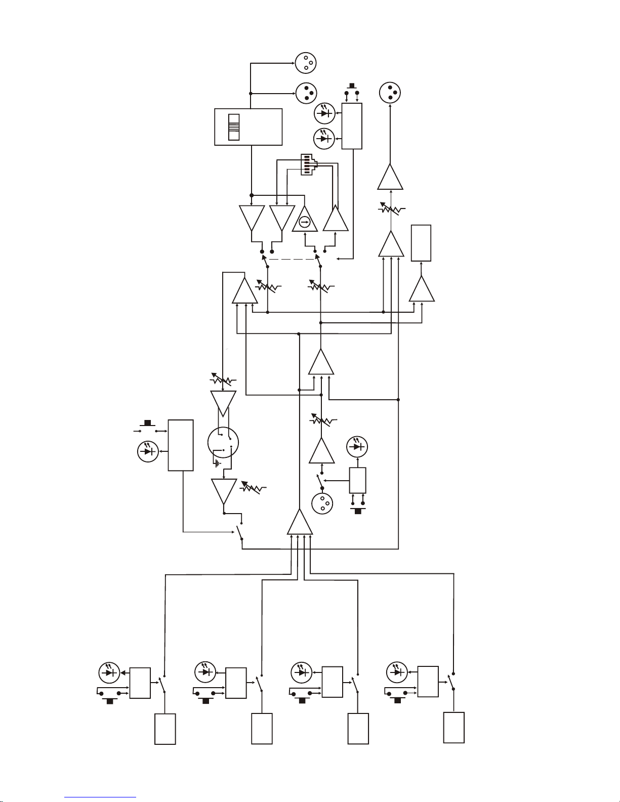
PORTABLE
STATION 1
CONNECT
RECEIVE
1
LOGIC
PORTABLE
STATION 2
CONNECT
LOGIC
RECEIVE
2
PORTABLE
STATION 3
CONNECT
LOGIC
RECEIVE
3
PORTABLE
STATION 4
CONNECT
RECEIVE
4
LOGIC
LOGIC
I/C
TEL
E
X
R
T
S
C
L
E
ARC
O
M
AUXILIARY
AUDIO
INPUT
XLR
FEMALE
ON/OFF
ON/O.M.
IN
INTERCOM
OUT
2 WIRE
INTERCOM
IN
RJ11
STYLE
4 WIRE
4 WIRE
2 WIRE
MALE
FEMALE
XLR
SELECT
LOGIC
INTERCOM
AUXILIARY
AUDIO
OUTPUT
XLR
MALE
OUT
TRANSMIT
MIC
GAIN
XLR
HEADSET
1
4
2
3
LOGIC
TALK
TALK
VOLUME
margaiD kcolB 007-RTB
1-2
Page 9
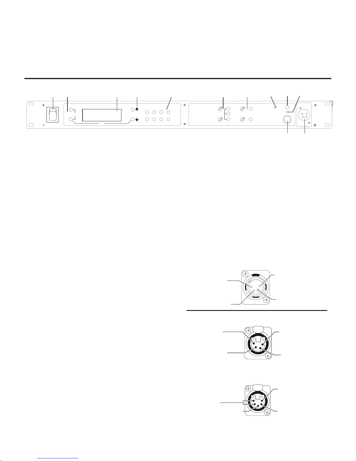
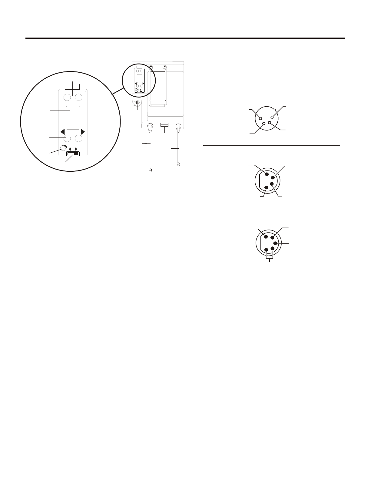
Con trols and Con nec tions - Front Panel
MIC GAIN
TALK/O.M.
VOLUME
ON/O.M.
ON/OFF
IN
OUT
AUXILIARY
2 WIRE
4 WIRE
SELECT
IN
OUT
PORTABLE STATION CONNECT
1 2
3
4
UP
DOWN
MENU
SET
RadioCom
ä
ClearScan
TM
COPY
1
2
3
4
5
6
7
8
9
10
11
12
INTERCOM
BTR-700
TALK
(1) Microphone
Shield (-)
(2) Microphone
Audio (+)
(3) Headphone
High (+)
(4) Headphone
Low (-)
(4) Headphone
Low (-)
(3) Headphone
High (+)
(1) Microphone
Shield (-)
(2) Microphone
Audio (+)
PUSH
(5) (4) Headphone
Low (-)
(3) Headphone
High (+)
(1) Microphone
Shield (-)
(2) Microphone
Audio (+)
PUSH
BTR-700 - Front Panel
1.
Power switch.
2. [Menu] and [Set] but tons – Used to se lect menus and set
op tions on the LCD.
3. Backlit Graph ics LCD (Liq uid Crys tal Dis play).
4. [Up] and [Down] but tons – Used to se lect base sta tion
op tions on the LCD.
5. Por ta ble Sta tion Con nect – But tons used to en able or
dis able the re spec tive re ceiver’s au dio. GREEN LED =
Au dio en abled, LED OFF = Au dio dis abled.
6. In ter com Con trols - Wired in ter com in ter face con trols.
Au dio in put and out put level con trols. 2-wire or 4-wire se lect but ton with green LED in di ca tor lights. Se lected LED
will change to RED if the in put lev els are too high.
Fig ure 1
Section
2
BTR-700 Base Sta tion
10.
Mi cro phone Gain – Ad justs the head set’s mi cro phone
gain. Ad justs so that the overmod light #9 flashes from
green to red on loud est speech.
11. Talk But ton – Press to en able the au dio path from the lo cal
head set. LED #9 will turn green when en abled. A quick
press and re lease latches but ton on. If the talk func tion is
latched on, press ing the talk but ton again will turn it off.
12. Lo cal Head set Con nec tor – Male XLR con nec tor for
Telex units, Fe male XLR con nec tor for RTS units. A dy namic or electret head set mi cro phone is au to mat i cally de tected.
Telex Units
7. Aux il iary Con trols - Wired aux il iary in ter face con trols.
Au dio in put and out put level con trols. GREEN LED =
Aux. in put en abled. LED will change to RED if the in put
lev els are too high.
8. Head set Vol ume – Con trols the vol ume to the head set
con nected to #12.
9. Talk/Overmod Light – LED is green when talk but ton
#11 is ac tive. A nor mal mic. gain set ting will cause the
LED to flash red on the loud est speech lev els. If the gain
is too high, the LED will be red at nor mal speech vol umes.
RTS Units
Fig ure 2
Lo cal Head set Wiring
2-1
Page 10

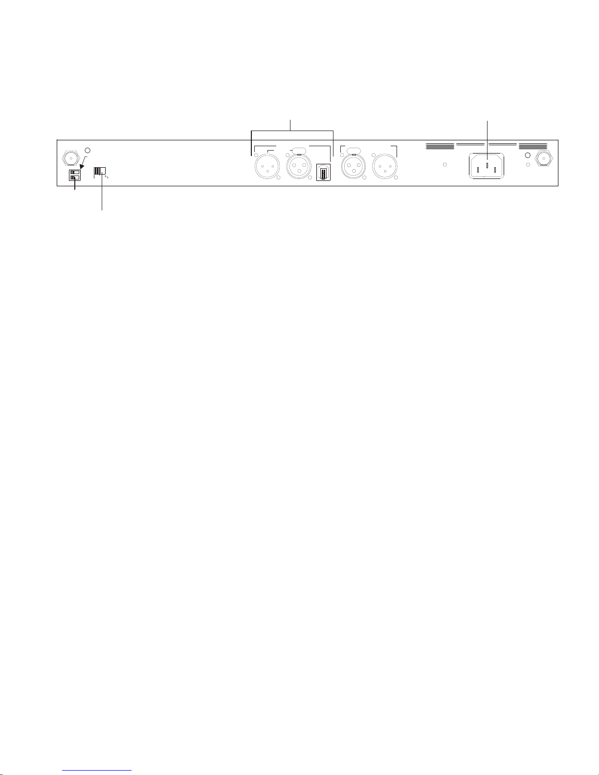
Con trols and Con nec tions - Rear Panel
RECEIVE
HIGH
ON
NORM
OFF
TRANSMIT
POWER
I/C
TELEX CLEARCOM
RTS
BTR-700
FCC ID: B5DM516
CANADA 1321231218A
INTERCOM
2 WIRE
L
O
O
P
T
H
R
U
4 WIRE
AUXILIARY AUDIO
INPUT OUTPUT
POWER
100-240 VAC 50-60 Hz
TRANSMIT
PUSHPUSH
1
2
3
4
5
6
7
8
TELEX COMMUNICATIONS INC.
MADE IN USA
BTR-700 - Rear Panel
1. Re ceive An tenna - Fe male “TNC” Con nec tor. Color band
on an tenna must match color dot on base sta tion.
2. Trans mit Power Switch – HIGH = Trans mit ter at full
power. NORMAL = Trans mit ter 10dB be low full power.
3. Trans mit ON/OFF Switch – Turns the trans mit ter on or off.
4. I/C Se lect Switch – Set to the ap pro pri ate 2-wire in ter com
type be ing in ter faced to the unit. Set to ei ther Telex, RTS
or Clear-Com®.
Fig ure 3
5. In ter com – In ter face to wired in ter com sys tem .
2-Wire – Male and Fe male 3 pin XLR con nec tors
wired in par al lel. The con nec tors are switched to the
ap pro pri ate in ter com con fig u ra tion via the I/C Se lect
Switch.
4-Wire – An RJ-11 type jack com pat i ble with “Ma trix” type in ter com sys tems.
6. Aux il iary In put/Out put – One 3 pin fe male XLR in put
con nec tor and one 3 pin male XLR out put con nec tor.
7. Power – IEC re cep ta cle. Ac cepts 100 – 240VAC, 50 – 60 Hz
8. Trans mit An tenna - Fe male “TNC” Con nec tor. Color
band on an tenna must match color dot on base sta tion.
2-2
Page 11

BTR-700
Spec i fi ca tions
Over all
RF Fre quency Range.........518 - 608 MHz, 614 - 740 MHz, 796 - 868 MHz in 18 MHz TX and RX bands
Power Re quire ments .......................................100-240 VAC, 50-60 Hz, IEC re cep ta cle
Tem per a ture Range ..............................................-4° F to 130° F (-20° C to 55° C)
Di men sions .............................19.00” W x 1.72” H x 14.00” D (48.3 cm x 4.4 cm x 35.6 cm)
Weight ...................................................................7 lbs 2 oz (3.24 kg)
TX An tenna ............................................1/2 Wave (sup plied), TNC Male Con nec tor
RX An tenna ............................................1/2 Wave (sup plied), TNC Male Con nec tor
FCC ID: .........................................................................B5DM516
Fre quency Re sponse..............................................................300Hz-8kHz
Four Wire In put ................................................Level Ad just able (2 Vrms typ i cal)
Four Wire Out put ...............................................Level Ad just able (2 Vrms typ i cal)
Telex In ter com....................In put/Out put Level Ad just able (1 Vrms typ i cal), Line im ped ance 300W
RTS In ter com .................In put/Out put Level Ad just able (0.775 Vrms typ i cal), Line Im ped ance 200W
ClearCom® In ter com.............. In put/Out put Level Ad just able (1 Vrms typ i cal), Line Im ped ance 200W
Aux il iary In put ......................................................Ad just able (2 Vrms typ i cal)
Aux il iary Out put ............................................Ad just able (2 Vrms typ i cal into 600W)
Mi cro phone in put sen si tiv ity .............................................................9mV
Lo cal Head set Out put ......................................40mW out put into 600W (1% Dis tor tion)
Trans mit ter
Type ......................................................Syn the sized Trans mit ter, 712 chan nels
Trans mit Power ..............................................50mW Max. (High), 5 mW (Nor mal)
Mod u la tion Type ........................................................................FM
De vi a tion .............................................................40 kHz (35 kHz Eu rope)
RF Fre quency Sta bil ity................................................................0.005%
Mod u la tion Lim iter ................................................Peak-Responding Com pres sor
Ra di ated Har monics & Spu ri ous ........................................Ex ceeds FCC spec i fi ca tions
Re ceiver
Type ..........Dual Con ver sion Super het ero dyne, four In de pend ent Syn the sized IFs, FM, 712 chan nels each
RF Sen si tiv ity........................................................<0.8 µV for 12 dB SINAD
Squelch Thresh old ..............................................................20 dB SINAD
IF Se lec tiv ity.................................................................3 dB at 230 kHz
Im age Re jec tion ...............................................................70 dB or better
Squelch Quieting......................................................................90 dB
RF Fre quency Sta bil ity................................................................0.005%
Dis tor tion ...............................................................<1% at full de vi a tion
2-3
Page 12

2-4 Blank
Page 13
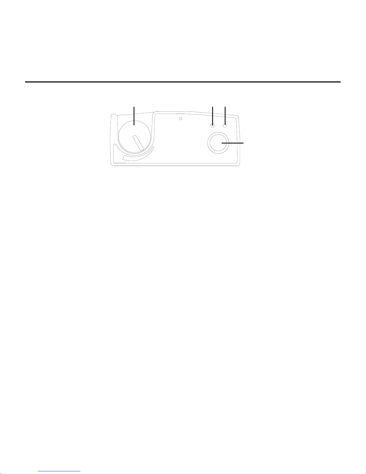
Con trols and Con nec tions - Top Panel
VOL
OFF
Telex
R
BAT/OM TALK
TALK
1
243
Section
3
TR-700 Beltpack
Fig ure 4
TR-700 Top Panel
1. On/Off & Vol ume Con trol – Turns the beltpack power
on and con trols head set vol ume.
2. Bat/Overmod Light – Light will flash once when unit is
turned on if the bat tery is good. If the light stays on, bat tery is low. If the light does not flash, bat tery is dead. A
nor mal microphone gain set ting will cause the LED to
flash at the be gin ning of most words at nor mal speech
levels. If the gain is too large, the LED will be red dur ing
the com plete word at nor mal speech lev els.
3. Talk Light – LED is on when the talk but ton is ac tive.
4. Talk but ton – Press to en able the au dio path from the lo -
cal head set microphone. The “TALK” LED, #3, will turn
red when en abled. A quick press and re lease latches the
talk function, un less latch ing has been dis abled in soft ware. Holding the but ton for over ½ a sec ond will cause
the au dio path to be en abled only for as long as the but ton
is held. If the talk function is latched on, press ing the talk
but ton again will turn it off.
3-1
Page 14
Con trols and Con nec tions - Rear Panel
(1) Microphone
Shield (-)
(2) Microphone
Audio (+)
(4) Headphone
Low (-)
(3) Headphone
High (+)
(1) Microphone
Shield (-)
(4) Headphone
Low (-)
(3) Headphone
High (+)
(2) Microphone
Audio (+)
MENU
SET
M
I
C
P
T
T
X
PT
T
A
LK
6
7
8
9
MENU
SET
M
I
C
P
T
TX
PT
T
AL
K
2
1
3
4
5
(1) Microphone
Shield (-)
(5) (4) Headphone
Low (-)
(3) Headphone
High (+)
(2) Microphone
Audio (+)
6. Head set Con nec tor – Male XLR con nec tor for Telex
units, Fe male XLR con nec tor for RTS units. A dy namic or
electret head set mi cro phone is au to mat i cally de tected by
the beltpack and a bias volt age sup plied if needed.
Telex Units
RTS Units
Fig ure 5
TR-700 Rear Panel/Con nec tor/An tennas
1. [MENU] and [SET] but tons – Used to se lect menus and
set op tions on the LCD.
2. LCD (Liq uid Crys tal Dis play)
3. [UP] and [DOWN] but tons – Used to se lect beltpack op -
tions on the LCD.
4. Mi cro phone Gain – Ad justs the head set’s mi cro phone
gain. Ad just so that the BAT/OM LED will flash at the be gin ning of most words at nor mal speech levels
5. Push-to-Talk/Push-to-Transmit Switch –
Push-to-Talk (PT TALK) – The trans mit ter is al ways
on. No au dio is sent un less the talk but ton is pressed.
Rec om mended po si tion.
Push-to-Transmit (PT TX) - The trans mit ter and au dio paths are off ex cept when the talk but ton is
pressed.
Fig ure 6
Head set Jack Wiring
7. Bat tery Latch – Press down to en able the bat tery pack to
be re leased. While the latch is held down, slide the bat tery
pack about 1/8 inch back, to ward the latch, un til it stops.
Then lift out.
8. Re ceive An tenna – Screw type ¼ wave re place able an tenna. The re ceiver an tenna is al ways the lon ger an tenna.
Color dot on the screw end of the an tenna must match
color dot on an tenna re cep ta cle.
9. Trans mit An tenna – Screw type ¼ wave re place able an tenna. Color dot on the screw end of the an tenna must
match color dot on an tenna re cep ta cle.
3-2
Page 15

TR-700
Spec i fi ca tions
RF Fre quency Range.........518 - 608 MHz, 614 - 740 MHz, 796 - 868 MHz in 18 MHz TX and RX bands
Power Re quire ments........................................6 “AA” Cells Al ka line (NiMH op tional)
Cur rent Draw ...................................................140 mA (Push-to-Talk, Talk On)
Tem per a ture Range ..............................................-4° F to 130° F (-20° C to 55° C)
Di men sions .................................3.75”W x 5.05”H x 1.65” D (9.5 cm x 12.8 cm x 4.2 cm)
Weight ......................................................16 oz (454g) with al ka line batteries
TX An tenna..........................................1/4 Wave (sup plied), Screw type, Replaceable
RX An tenna..........................................1/4 Wave (sup plied), Screw type, Replaceable
FCC ID: .........................................................................B5DM515
Fre quency Re sponse..............................................................300Hz-8kHz
Mi cro phone in put sen si tiv ity .............................................................7 mV
Lo cal Head set Out put ......................................40 mW out put into 600W (1% dis tor tion)
Trans mit ter
Type ...............................................................Syn the sized, 712 chan nels
Trans mit Power ..............................................50 mW Max. (auto-power reduction)
Mod u la tion Type ........................................................................FM
De vi a tion .............................................................40 kHz (35 kHz Eu rope)
RF Fre quency Sta bil ity................................................................0.005%
Mod u la tion Lim iter ................................................Peak-Responding Com pres sor
Ra di ated Har monics & Spu ri ous ........................................Ex ceeds FCC spec i fi ca tions
Re ceiver
Type ...............................Dual Con ver sion Super het ero dyne, Syn the sized, FM, 712 chan nels
RF Sen si tiv ity........................................................<0.7 µV for 12 dB SINAD
Squelch Thresh old .................................................20 dB SINAD (About 1.0 µV)
IF Se lec tiv ity.................................................................3 dB at 230 kHz
Im age Re jec tion ...............................................................70 dB or better
Squelch Quieting......................................................................90 dB
RF Fre quency Sta bil ity................................................................0.005%
Dis tor tion ...............................................................<1% at full de vi a tion
3-3
Page 16

3-4 Blank
Page 17

Un packing
Section
4
Ini tial Equip ment Set-Up
Un pack your RadioCom™ Sys tem. Be low are the items that
should come with your base sta tion and each belt pack.
Quan tity De scrip tion
BTR-700
1 BTR-700 Base Sta tion
1 Op er ating In struc tions
1 Power Cord
2 An tennas (one Trans mit and one Re ceive)
1 War ranty Card
1 Screwdriver
1 Warn ing Card
4 Rub ber feet
Con tact the ship per or your dealer im me di ately if any thing is
dam aged or miss ing. Fill out the reg is tra tion card and re turn it
to Telex to reg is ter the unit.
TR-700
Quan tity De scrip tion
1 TR-700 with Antennas
1 Bat tery pack
1 In struc tion Sheet
1 Screwdriver
1 War ranty Card
4-1
Page 18
An tenna Con nec tion
T
e
l
e
x
O
F
F
B
A
T
/
O
M
T
A
L
K
R
a
d
i
o
C
o
m
T
R
-
7
0
0
T
M
VOL
MIC GAIN
TALK/O.M.
VOLUME
ON/O.M.
ON/OFF
IN
OUT
AUXILIARY
2 WIRE
4 WIRE
SELECT
IN
OUT
PORTABLE STATION CONNECT
1 234
UP
DOWN
MENU
SET
RadioCom
ä
ClearScan
TM
COPY
INTERCOM
BTR-700
TALK
T
e
l
e
x
O
F
F
B
A
T
/
O
M
T
A
L
K
R
a
d
i
o
C
o
m
T
M
VOL
TR-700TR-700
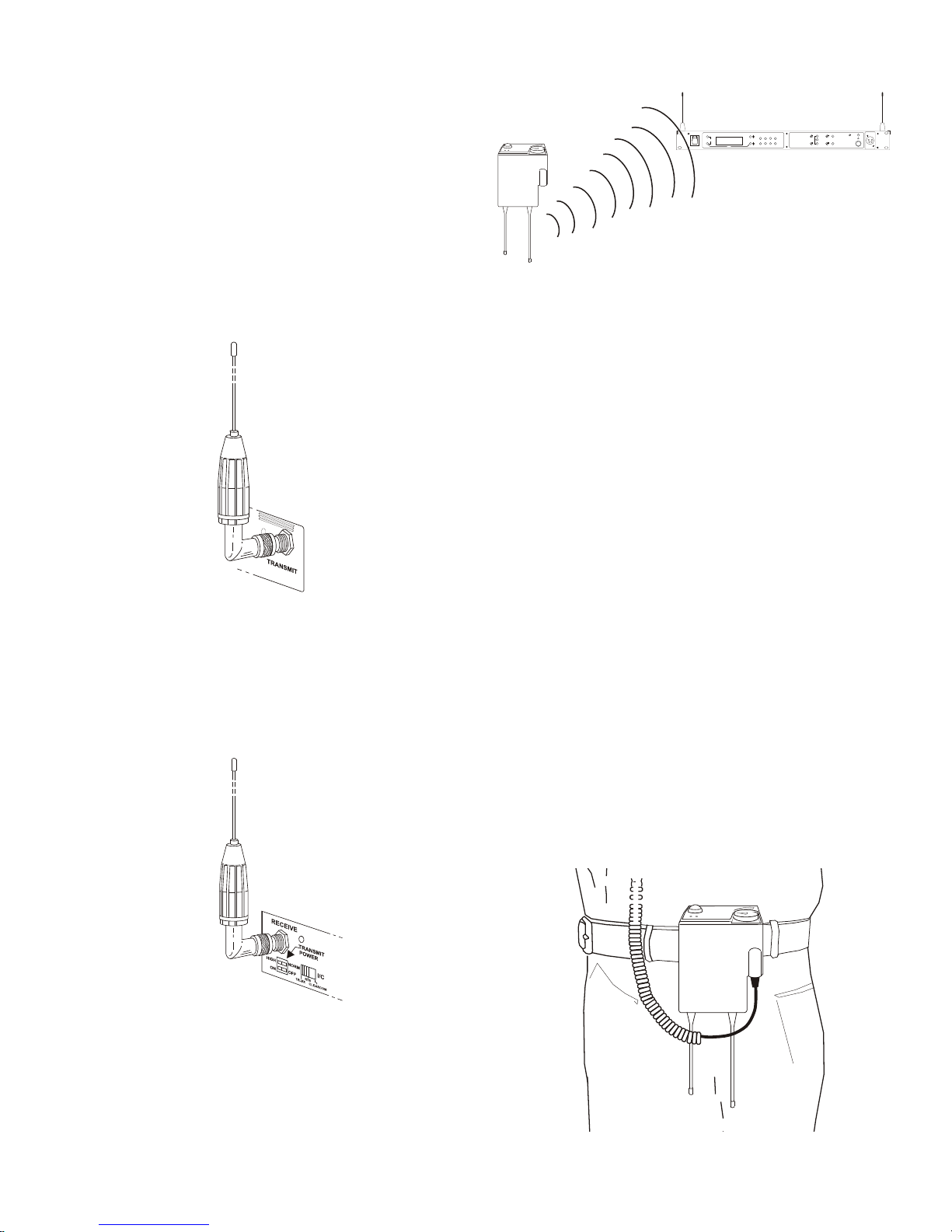
The base sta tion is sup plied with two (2) an ten nas. One
1/2-wave an tenna for Trans mit and one 1/2-wave for Re ceive.
The an ten nas have TNC male con nec tors.
The fre quency range of the an ten nas should match the re ceiver
and trans mit ter of the base sta tion. Match the color code on
the an tenna with the color code on the base sta tion.
At tach the transmit 1/2-wave an tenna to the an tenna in put re --
cep ta cle la beled “Trans mit” on the right side of the rear panel.
The an tenna should be ver ti cally aligned.
Fig ure 7
Attaching Trans mit 1/2-Wave An tenna
At tach the receive 1/2-wave an tenna to the an tenna in put re --
cep ta cle la beled “Re ceive” on the left side of the rear panel.
The an tenna should be ver ti cally aligned.
ANTENNAS SHOULD BE VERTICAL
Fig ure 9
Ver ti cally Po lar ized An tennas
Dis tance be tween An tennas
The dis tance be tween the base sta tion’s re ceive and trans mit
an ten nas is not ad just able when the an ten nas are con nected di --
rectly on the back of the unit.
The an ten nas can be remoted for better sig nal path. A Telex
coax as sem bly with re mote an ten nas may be re quired. See
“Ac ces sory” sec tion for or der ing in for ma tion.
NOTE: If your base sta tion is to be lo cated in a shielded rack
mount en clo sure or other poor RF lo ca tion, you must re mote
the 1/2-wave an ten nas with coax as sem blies. See “Ac ces sories
and Re place ment Parts” sec tion for remote mount ing hard --
ware.
An tenna Place ment
Proper an tenna place ment prob a bly has the most ef fect on
your TELEX Wire less In ter com Sys tem’s over all per for --
mance. The fol low ing sug ges tions will re sult in op ti mum per --
for mance.
Proper place ment of the beltpack can be crit i cal. The an ten nas
should be in the open. Bending the an ten nas up and plac ing
the beltpack in a pocket, etc., will re duce sys tem dis tance.
It is sug gested that the unit be worn on the belt or pocket with
both an tenna’s ver ti cal for best op er at ing range and per for --
mance.
Fig ure 8
Attaching Receive 1/2-Wave An tenna
An tenna Po lar iza tion
The Telex Wire less In ter com Sys tem is “Ver ti cally Po lar ized”.
This means both the trans mit ting and re ceiv ing an ten nas
should op er ate in the ver ti cal po si tion.
Fig ure 10
Proper Dress ing of the An tennas
4-2
Page 19
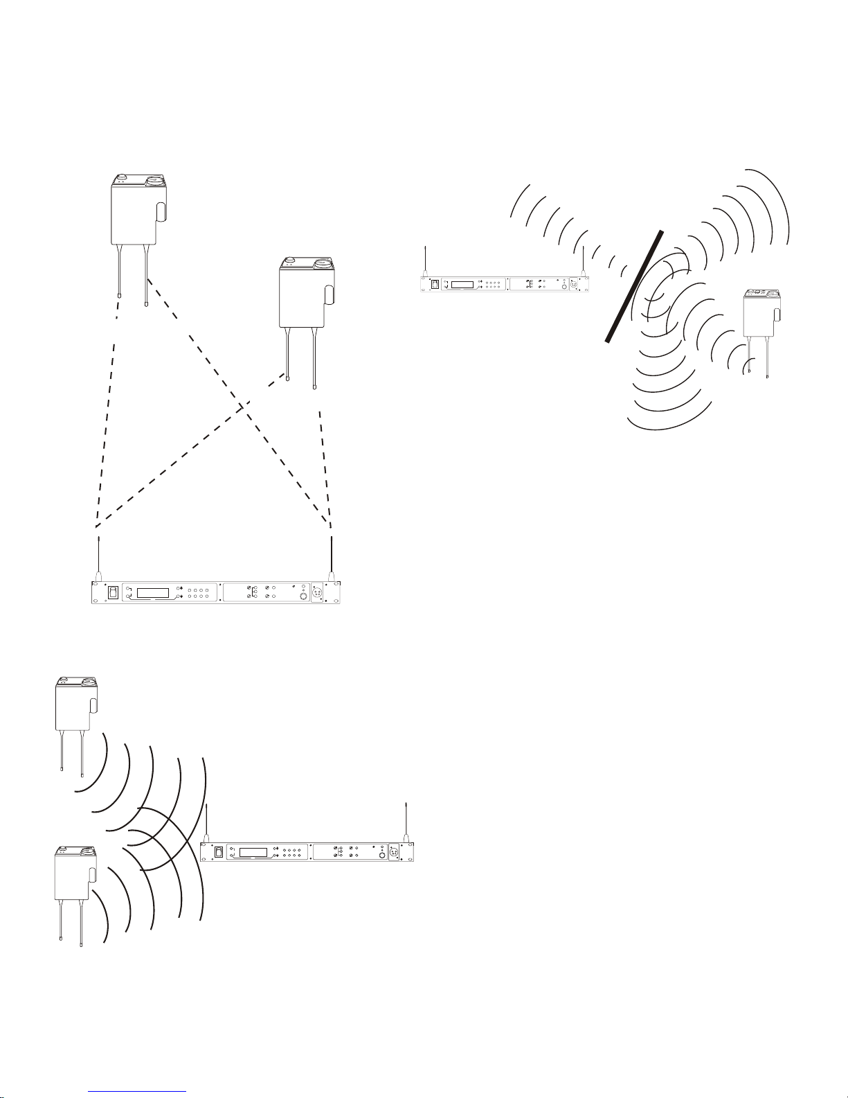
Keep the dis tance be tween the base sta tion and the beltpacks
700 FEET
100 FEET
T
e
l
e
x
O
F
F
B
A
T
/
O
M
T
A
L
K
R
a
d
i
o
C
o
m
T
R
-
7
0
0
T
M
VOL
T
e
l
e
x
O
F
F
B
A
T
/
O
M
T
A
L
K
R
a
d
i
o
C
o
m
T
R
-
7
0
0
T
M
VOL
MIC GAIN
TALK/O.M.
VOLUME
ON/O.M.
ON/OFF
IN
OUT
AUXILIARY
2 WIRE
4 WIRE
SELECT
IN
OUT
PORTABLE STATION CONNECT
1 234
UP
DOWN
MENU
SET
RadioCom
ä
ClearScan
TM
COPY
INTERCOM
BTR-700
TALK
T
e
l
e
x
O
F
F
B
A
T
/
O
M
T
A
L
K
R
a
d
i
o
C
o
m
T
R
-
7
0
0
T
M
VOL
T
e
l
e
x
O
F
F
B
A
T
/
O
M
T
A
L
K
R
a
d
i
o
C
o
m
T
R
-
7
0
0
T
M
VOL
MIC GAIN
TALK/O.M.
VOLUME
ON/O.M.
ON/OFF
IN
OUT
AUXILIARY
2 WIRE
4 WIRE
SELECT
IN
OUT
PORTABLE STATION CONNECT
1 234
UP
DOWN
MENU
SET
RadioCom
ä
ClearScan
TM
COPY
INTERCOM
BTR-700
TALK
T
e
l
e
x
W
T
A
A
B
O
F
F
B
A
T
/
O
M
T
A
L
K
R
a
d
i
o
C
o
m
T
R
-
8
0
0
T
M
VOL
SA
MIC GAIN
TALK/O.M.
VOLUME
ON/O.M.
ON/OFF
IN
OUT
AUXILIARY
2 WIRE
4 WIRE
SELECT
IN
OUT
PORTABLE STATION CONNECT
1 234
UP
DOWN
MENU
SET
RadioCom
ä
ClearScan
TM
COPY
INTERCOM
BTR-700
TALK
as short as pos si ble. The greater the dis tance, the weaker the
sig nal. Make sure the “sig nal paths” be tween the base sta tion
and beltpacks are un ob structed. You should be able to vis i bly
lo cate the base sta tion an ten nas at all times for best per for --
mance.
At tempting to op er ate the wire less in ter com sys tem through or
around walls, ceil ings, metal ob jects, etc. will re duce sys tem
range and per for mance.
Fig ure 13
Op er ating Sys tem Near Obstructions
DO NOT - mount the base sta tion 1/2-wave an ten nas on, or
next to metal, such as beams, walls with metal studs, equip --
ment racks, etc. This also ap plies to the an ten nas when as sem --
bled di rectly to the Base Sta tion. This will “de tune” the
Fig ure 11
Dis tance Be tween base sta tion and beltpack
an ten nas which can re sult in noise or loss of RF sig nal at the
Base Sta tion, see Fig ure 13.
Fig ure 12
Keeping Site Clear to An tenna
4-3
Page 20
T
elex
T
elex
T
elex
#1
#2
#3
MIC GAIN
TALK/O.M.
VOLUME
ON/O.M.
ON/OFF
IN
OUT
AUXILIARY
2 WIRE
4 WIRE
SELECT
IN
OUT
PORTABLE STATION CONNECT
1 234
UP
DOWN
MENU
SET
RadioCom
ä
ClearScan
TM
COPY
MIC GAIN
TALK/O.M.
VOLUME
ON/O.M.
ON/OFF
IN
OUT
AUXILIARY
2 WIRE
4 WIRE
SELECT
IN
OUT
PORTABLE STATION CONNECT
1 234
UP
DOWN
MENU
SET
RadioCom
ä
ClearScan
TM
COPY
MIC GAIN
TALK/O.M.
VOLUME
ON/O.M.
ON/OFF
IN
OUT
AUXILIARY
2 WIRE
4 WIRE
SELECT
IN
OUT
PORTABLE STATION CONNECT
1 234
UP
DOWN
MENU
SET
RadioCom
ä
ClearScan
TM
COPY
MIC GAIN
TALK/O.M.
VOLUME
ON/O.M.
ON/OFF
IN
OUT
AUXILIARY
2 WIRE
4 WIRE
SELECT
IN
OUT
PORTABLE STATION CONNECT
1 234
UP
DOWN
MENU
SET
RadioCom
ä
ClearScan
TM
COPY
MIC GAIN
TALK/O.M.
VOLUME
ON/O.M.
ON/OFF
IN
OUT
AUXILIARY
2 WIRE
4 WIRE
SELECT
IN
OUT
PORTABLE STATION CONNECT
1 234
UP
DOWN
MENU
SET
RadioCom
ä
ClearScan
TM
COPY
INTERCOM
BTR-700
TALK
INTERCOM
BTR-700
TALK
INTERCOM
BTR-700
TALK
INTERCOM
BTR-700
TALK
INTERCOM
BTR-700
TALK
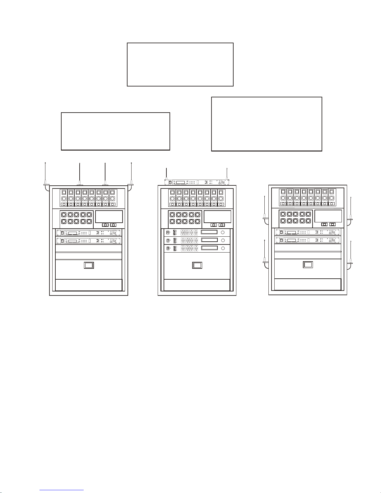
2. Placing the BTR on top of a
shelf or equip ment rack un ob structed with out remoting
the an ten nas is OK.
1. Placing BTRs in a shelf or
equip ment rack and us ing re mote an ten nas is OK.
3. Placing BTRs in a shelf or
equip ment rack with the an ten nas mounted on the back
of the BTR or the side of the
rack is BAD.
Im proving Re cep tion and In creasing
Range
Keeping the dis tance from the base sta tion and beltpack as
short, and un ob structed as pos si ble will pro duce the most re li --
able per for mance.
An tenna Placement
Fig ure 14
The base sta tion is sup plied with two an ten nas. This should
pro vide sat is fac tory sys tem per for mance in most ap pli ca tions.
Sys tem range can be en hanced by remoting the 1/2-wave an --
ten nas.
4-4
Page 21
Base Sta tion Set-up
RECEIVE
HIGH
ON
NORM
OFF
TRANSMIT
POWER
I/C
TELEX CLEARCOM
RTS
INTERCOM
2 WIRE
L
O
O
P
T
H
R
U
4 WIRE
AUXILIARY AUDIO
INPUT OUTPUT
POWER
100-240 VAC 50-60 Hz
TRANSMIT
PUSHPUSH
TRANSMIT
SWITCHES
INTERCOM
SWITCH
INTERCOM
INTERFACE
POWER CONNECTION
BTR-700
FCC ID: B5DM516
CANADA 1321231218A
TELEX COMMUNICATIONS INC.
MADE IN USA
Fig ure 15
Base Sta tion - Rear Panel
Lo ca tion
Lo cate the base sta tion with the front and rear of the unit ac --
ces si ble so that switches may be set and con nec tions made.
Place the transmit and re ceive an ten nas on the base sta tion.
Make sure the an tenna’s color band match the color dot near
each an tenna. See “An tenna In for ma tion” sec tion for more in --
for ma tion on choos ing a proper op er at ing lo ca tion.
Power Con nec tion
Plug the sup plied power cord into the unit. The base sta tion has
an IEC power re cep ta cle that ac cepts 100 – 240VAC, 50 – 60Hz.
The spe cific re cep ta cle type is an IEC 60320/C14. The cord it ac --
cepts is an IEC 60320/C13. These cords are com mon and avail --
able through many re tail hard ware/elec tronic stores if the cord is
lost.
Trans mit Switches
There are two switches lo cated on the lower left side of the rear
panel. The up per switch sets the trans mit power lev el to high or
nor mal. The lower switch turns the trans mit ter on or off.
Trans mit Power
Set the power level to nor mal if us ing the beltpacks at
close to me dium dis tances (<200 feet, 161m,
line-of-sight) from the base sta tion. Set the power level to
high if us ing the beltpacks at a dis tance (>200 feet, 161m,
line-of-sight) from the base sta tion.
On/Off
Set the trans mit ter switch to on for nor mal use. In the off
po si tion the base station transmitter is dis abled. Set ting
the switch to off will dis ables all the beltpacks from hear --
ing any one else or even their own sidetone.
4-5
Page 22

In ter com Switch
NC
AUDIO IN +
AUDIO OUT +
AUDIO OUT -
AUDIO IN -
NC
PIN 6 5 4 3 2 1
In ter com In ter face
The Radiocom™ wire less sys tem can be in ter faced to RTS
TW, Audiocom® (Telex), Clear-Com®, RTS ma trix and other
in ter com (I/C) sys tems. Set the In ter com switch on the rear of
the unit to the ap pro pri ate sys tem and con nect the sys tem to
the base sta tion. The in ter com chan nel on the rear of the base
sta tion has loop-thru male and fe male XLR con nec tions for
two-wire sys tems and a RJ-11 type jack for four-wire sys tems.
This switch only af fects the two-wire in ter com sys tems. The
func tions of the I/C XLRs change de pend ing on the in ter com
se lected. Please see Sec tion 11 for pinout in for ma tion of the
dif fer ent two-wire in ter com sys tems.
Telex (Audiocom®) and Clear-Com® in ter com sys tems re --
quire one ca ble for in ter com. This in ter fac ing is done through
the I/C 3 pin XLR con nec tors on the rear of the unit.
RTS TW in ter coms also only need to con nect one 3 pin ca ble
to one of the two in ter com XLR con nec tors. Two chan nels of
au dio are car ried on one ca ble for RTS. RTS chan nel 1 is
placed on the in ter com nor mally. Switch the rear panel I/C
switch to Clear-Com® to in ter face only to RTS au dio channel
2. Once again, leave it in RTS to in ter face to only RTS audio
Chan nel 1.
Four wire in ter com sys tems re quire only one ca ble for the in --
ter com to in ter face four wire in ter com to the base sta tion. This
in ter fac ing is done through the I/C RJ-11 type jacks on the
rear of the unit. See Fig ure 16 for the pinout of the RJ-11
jacks.
Fig ure 16
RJ-11 Type/ Four-wire Pinout
4-6
Page 23

T
e
l
e
x
O
F
F
B
A
T
/
O
M
T
A
L
K
R
a
d
i
o
C
o
m
T
R
7
0
0
T
M
VOL
T
e
l
e
x
O
F
F
B
A
T
/
O
M
T
A
L
K
R
a
d
i
o
C
o
m
T
R
7
0
0
T
M
VOL
T
e
l
e
x
O
F
F
B
A
T
/
O
M
T
A
L
K
R
a
d
i
o
C
o
m
T
R
7
0
0
T
M
VOL
T
e
l
e
x
O
F
F
B
A
T
/
O
M
T
A
L
K
R
a
d
i
o
C
o
m
T
R
7
0
0
T
M
VOL
MODEL PS15
POWER SUPPLY
O/N 9000678600
IMPEDANCE
SELECT
NORM
200
DUAL
400
OUTPUTS
J1, J2 CONNECT TO
J1 J2
TW INTERCOM SYSTEM COMPONENTS
REFER TO OPERATION MANUAL
AUDIO
COUPLING
CM1-CM2
J3
TIP-CH1
RING-CH2
SLEEVE-COM
RTS SYSTEMS, BURBANK CALIFORNIA MADE IN U.S.A.
FUSE
0.5A S8/120 VAC
CAUTION
FOR CONTINUED PROTECTION AGAINST FIRE
REPLACE ONLY WITH SAME TYPE FUSE.
CHN 1CHN 1
HEADSET
LINE
HEADSET
LINE
HEADSET
LINE
HEADSET
LINE
INTERCOM
POWER SUPPLY
RTS DISTRIBUTION
PANEL (TW5W)
BP-318
BP-350
BP-350
BP-318
BTR-700
TR-700s
(PS15)
RECEIVE
HIGH
ON
NORM
OFF
TRANSMIT
POWER
I/C
TELEX CLEARCOM
RTS
INTERCOM
2 WIRE
L
O
O
P
T
H
R
U
4 WIRE
AUXILIARY AUDIO
INPUT OUTPUT
POWER
100-240 VAC 50-60 Hz
TRANSMIT
PUSHPUSH
BTR-700
FCC ID: B5DM516
CANADA 1321231218A
TELEX COMMUNICATIONS INC.
MADE IN USA
RECEIVE
HIGH
ON
NORM
OFF
TRANSMIT
POWER
I/C
TELEX CLEARCOM
RTS
INTERCOM
2 WIRE
L
O
O
P
T
H
R
U
4 WIRE
AUXILIARY AUDIO
INPUT OUTPUT
POWER
100-240 VAC 50-60 Hz
TRANSMIT
PUSHPUSH
AUXILIARY
INTERFACE
BTR-700
FCC ID: B5DM516
CANADA 1321231218A
TELEX COMMUNICATIONS INC.
MADE IN USA
Fig ure 17
Ex am ple In ter face to an RTS TW Sys tem
Aux il iary In put/Out put
The in put and out put 3-pin aux il iary con nec tions are for sup --
ply ing ad di tional bal anced au dio into and re ceiv ing bal anced
au dio from the base sta tion. The in put and out put aux il iary
au dio is global. This means the in put and out put aux il iary au --
dio is placed on the base lo cal head set, beltpack(s) head sets
and any wired in ter com sys tem in ter faced to the base sta --
tion.
Base Sta tion - Rear Panel
A mod i fi ca tion doc u ment is avail able from Telex
Communications for those who wish to mod ify the base sta --
tion so that aux il iary in put au dio is heard only lo cally; base lo --
cal head set and beltpack(s) head sets.
4-7
Page 24

Beltpack Set-up
Bat tery In stal la tion
En sure that the On/Off vol ume con trol knob is turned off.
Press down and hold down the bat tery re lease latch, slide the
bat tery pack about 1/8 inch back, to ward the latch, un til it
stops. Then lift bat tery pack out. Re place bat ter ies as fol lows:
1. Open the bat tery pack by in sert ing
fin ger nail and lift ing.
2. Pull bat tery strap to re move low
or dead bat ter ies.
3. Load new bat ter ies fol low ing the
po lar ity as shown in bat tery case
4. Start load ing at the end of the case where
the strap is at tached to the case.
5. Be sure strap goes un der bat ter ies.
6. Tuck end of strap un der door
when plac ing the bat tery cover
back on the case.
WARNING
Do not place an al ka line TR bat tery
pack in any bat tery charger. Se vere
charger and bat tery pack dam age
may re sult.
Fig ure 18
Bat tery In stal la tion
4-8
Page 25

MENU
SET
M
I
C
P
T
T
X
PT
TA
L
K
MICROPHONE
GAIN CONTROL
TRANSMIT
SWITCH
HEADSET
CONNECTION
RECEIVE
ANTENNA
TRANSMIT
ANTENNA
BATTERY
RELEASE
LATCH
TR-700 Rear Panel
An tenna Con nec tion
The beltpack co mes with two de tach able, screw type, ¼ wave
an ten nas. To at tach the two an ten nas, screw into the re cep ta --
cles at the bot tom of the beltpack. The color dot on the screw
end of the an tenna must match the color dot on an tenna re cep --
ta cle. The lon gest an tenna is the re ceiver an tenna. It screws
into the left re cep ta cle if the beltpack is lay ing flat with the
bat tery com part ment face up and the an tenna re cep ta cles fac --
ing you. The other an tenna is the trans mit an tenna. New an --
tennas can be or dered if de sired, see the “Ac ces sories”
sec tion.
Fig ure 19
Head set Con nec tion
In sert the head set plug into the XLR con nec tor. See the head --
set pinout in the “TR-700 beltpack con trols and con nec tions”
sec tion if this is not a Telex head set. A dy namic or electret
head set mi cro phone is au to mat i cally de tected by the beltpack
and a bias volt age sup plied if needed.
Trans mit mode
The rear panel lo cated trans mit switch has the fol low ing two
modes:
Push-to-Talk (PT TALK) – Rec om mended po si tion –
The trans mit ter is al ways on. No au dio is sent un less the
talk switch is pressed.
Push-to-Transmit (PT TX) – The trans mit ter and au dio
paths are off ex cept when the talk switch is pressed.
4-9
Page 26

4-10 Blank
Page 27

Fol low ing the in struc tions fully to this point you have suc cess --
fully com pleted the fol low ing check list:
Lo cated the base sta tion prop erly.
❒
Con nected power to base sta tion.
❒
Con nected the 1/2-wave an ten nas to the base sta tion.
❒
Checked fre quency range of the an tennas with the fre quency of the base sta tion by cor rectly match ing color
codes.
Pre-Walk-Thru Check list
Con nected head sets to base sta tions (if needed) and all
beltpacks.
❒
Con nected the base sta tion to any aux il iary au dio, in ter com or ex ter nal P.A. sys tem.
❒
In stalled bat ter ies in the beltpack.
❒
Section
5
❒
❒
❒
❒
Con nected 1/4-wave an tenna to the beltpack. Checked
fre quency range of the an tennas with the fre quency of
the beltpack by cor rectly match ing color codes.
Base station trans mit power switches in the cor rect po si tions.
Trans mit mode switch on beltpack set correctly
Set wired in ter com type cor rectly.
If you missed any of the above in struc tions, go back
and com plete that in struc tion be fore go ing on.
❒
5-1
Page 28

5-2 Blank
Page 29

Fre quency Plan Over view
The BTR/TR-700 has 36 fac tory de fined fre quency groups
and 12 user-programmable fre quency groups. A Group de --
fines the base sta tion trans mit fre quen cy and thus the re ceive
fre quen cy on all the beltpacks. A Chan nel de fines a base sta --
tion re ceive fre quency and thus a beltpack trans mit frequency.
A base sta tion re ceive chan nel that does not have a fre quency
set for it will have a dash to the right of it on the Group/Chan --
nel se lect screen. De tails on set ting fre quen cies may be found
in the “BTR-700 Menu Struc ture” and “TR-700 Menu Struc --
ture” in struc tions in this sec tion.
Fac tory-Defined Groups
The 36 fac tory-defined groups were care fully cho sen to avoid
cer tain intermod prod ucts and var i ous other pos si ble sources
of in ter fer ence. The Groups are set and can not be changed.
There is a lim ited num ber of chan nels which can be chosen
from within these groups.
Section
6
System Op er a tion
Sys tem Quick Start
Fol low the list be low to quickly get a base sta tion and
beltpack(s) op er at ing. When com pleted the user should have a
base sta tion and 1 to 4 beltpacks up and run ning with full op er --
a tional abil ity. The base sta tion will be on Group 01A with its
four re ceiv ers on chan nels 01, 02, 03 and 04. Each beltpack
will be on Group 01A with a unique trans mit chan nel num ber
match ing one of the base sta tion re ceive chan nels.
1. Plug-in the base sta tion via the sup plied power cord and
con nect the an ten nas. The color dots on the base should
match the color rings on the an ten nas.
2. Base sta tion rear panel switches: Trans mit power set to
High and on.
3. En sure base sta tion rear panel IC switch matches at tached
wired in ter com sys tem. If used stand alone or con nected to
a 4-wire sys tem then IC switch po si tion is Not Ap pli ca ble.
The first 24 factory-defined groups (01A – 12B) are “pair”
groups that can be used for sin gle (up to 4 beltpacks) and dual
(up to 8 beltpacks) BTR-700 sys tems. They are ar ranged
01A, 01B, 02A, 02B…011B, 012A, 012B. A “pair” group,
like 1A and 1B, have dif fer ent base sta tion transmit fre quen --
cies, how ever, they both have the same eight base station re --
ceive chan nels from which to choose. Each chan nel rep re sents
a unique fre quency. For ex am ple, one BTR-700 could be set
on Group 02A and chan nels 01, 02, 03 and 04. The other
BTR-700 could be set on Group 02B chan nels 05, 06, 07 and
08. As long as the chan nels are dif fer ent, everything should
be fine.
The next 12 groups (13 – 24) are sin gle groups that primarily
are used for sin gle (up to 4 beltpacks) BTR-700 sys tems. The
num ber of chan nels from which to choose from in these
groups will vary from group to group.
User-Programmable Groups
The 12 user-programmable groups are ini tially empty. The
trans mit and re ceive fre quen cies are fully editable within these
groups. In fact, fac tory-defined groups may be cop ied to
user-programmable groups and then ed ited if de sired. See the
“BTR-700 Menu Struc ture” and “TR-700 Menu Struc ture” in --
struc tions in this sec tion for de tails on how to copy and edit
fre quen cies.
4. Press [MENU] as pow er ing-up the base sta tion. This will
place it on group 01A and set the re ceives on chan nels: 01,
02, 03, and 04.
5. Place the front panel IC “IN” and “OUT” level con trols in
the 12:00 o’clock po si tion. Check that front panel IC is in
2-wire for AudioCom (Telex), RTS - TW and
Clear-Com® wired sys tems, and 4-wire for RTS Ma trix
and stand-alone op er a tion.
6. Place bat ter ies in the beltpacks.
7. Re move the rear switch cover on the beltpacks. Set the
beltpack rear panel slide switch to push-to-talk (PT
TALK).
8. Press [MENU] as pow er ing-up each beltpack. This will
place the beltpack on group 01A with the chan nel 01
flash ing.
9. Use the [UP] and [DOWN] ar row but tons to change the
chan nel to match a channel on the base sta tion. Then press
[SET]. If leav ing on chan nel, just press [MENU]. Each
beltpack should have a unique chan nel num ber.
10. The group/chan nel on the beltpack should now match the
group and a re ceive chan nel on the base sta tion. Noth ing
should be flash ing on the beltpack screens.
11. Plug head sets into the beltpacks and set the mi cro phone
gain so the BAT/OM LED will flash at the be gin ning of
most words at nor mal speech lev els.
DONE.
6-1
Page 30

Base Sta tion Op er a tion
MIC GAIN
TALK/O.M.
VOLUME
ON/O.M.
ON/OFF
IN
OUT
AUXILIARYINTERCOM
2 WIRE
4 WIRE
SELECT
IN
OUT
PORTABLE STATION CONNECT
1 234
UP
DOWN
MENU
SET
RadioCom
ä
ClearScan
TM
COPY
POWER
PORTABLE STATION
CONNECT
INTERCOM
AUXILIARY
LOCAL
HEADSET
BTR-700
TALK
Base Sta tion - Front Panel
Power
If you have fol lowed the in struc tions in Sec tion 4, “Ini tial
Equip ment Set-Up”, you should now be ready to turn the base
sta tion on.
Set the base sta tion power switch to the on po si tion, by push --
ing the top of the switch.The in ter nal cool ing fan will start im --
me di ately and the LCD dis play and front panel in di ca tor lights
will come on in five or six sec onds.
Lo cal Head set
Talk But ton - Press to en able the au dio path from the lo cal
head set. The TALK/O.M. LED will turn green when au dio
is en abled. A quick press and re lease latches on the but ton.
If the talk function is latched on, press ing the talk but ton
again will turn it off. If the lo cal head set is not be ing used,
the talk but ton should be off. This keeps ad di tional noise
out of the sys tem.
Mi cro phone Gain - Ad justs the head set’s mi cro phone
gain. Ad just so the TALK/O.M. LED flashes from green
to red on loudest speech.
Vol ume - Ad just the vol ume to the head set by ro tat ing the vol --
ume con trol as re quired for a com fort able lis ten ing vol ume.
Por ta ble Sta tion Con nect
Se lect the au dio paths from the base sta tion’s four re ceiv ers that
you wish to en able. The cor re spond ing LED above the se lect
but ton is on when the au dio path is en abled. If a beltpack user
has their por ta ble sta tion con nect path off at the base, that user
will no lon ger hear their sidetone and their au dio will not be
passed to any one. The user will still be able to hear ev ery one.
The se lec tion is re tained in non-volatile mem ory, so it will
come-up where last left if the unit is power cy cled.
Al ways dis able un used au dio re ceive paths. This re duces the
chances that ex ter nal RF noise can get onto the au dio buses
via an open re ceiver.
In ter com
In ter com Se lect But ton - Press the [SE LECT] but ton to
choose be tween 2-wire or 4-wire in ter com sys tems. The
green LED will in di cate the cur rent mode of the in ter com
chan nel. If the base sta tion is con nected to a 2-wire sys --
tem, such as Audiocom (Telex), RTS TW or Clear-Com®,
set the in ter com to 2-wire. If it is con nected to a
four-wire sys tem, such as RTS Ma trix, set the in ter com to
4-wire. The se lec tion is re tained in non-volatile mem ory,
so it will come-up where last left if the unit is power cy --
cled.
In Level Con trol - Ad justs the au dio level of the wired
in ter com sys tem’s in put to the base sta tion.
Out Level Con trol - Ad justs the au dio level of the base
sta tion’s out put to the wired in ter com sys tem.
If the base sta tion is used stand-alone, no wired in ter com sys --
tem con nected, it must be set in the 4-wire mode. The 2-wire
mode re quires a wired in ter com sys tem or ap pro pri ate load be
con nected to the in ter com. If not loaded, a large gain in crease
will take place in the un load in ter com chan nel which may be
high enough to pro duce a loud “howl ing” sound.
Aux il iary
Aux il iary In put Se lect But ton - Press the [SE LECT]
but ton to turn on or off the aux il iary in put to the base sta --
tion. The se lec tion is re tained in non-volatile mem ory, so
it will come-up where last left if the unit is power cy cled.
In Level Con trol - Ad justs the au dio level of the wired
aux il iary sys tem’s in put to the base sta tion.
Out Level Con trol - Ad justs the au dio level of the base
sta tion’s out put to the aux il iary XLR plug.
The aux il iary out put is al ways avail able at the back panel out --
put XLR. It can not be switch on or off like the in put. Both the
in put and out put are bal anced au dio ports. Aux il iary in put and
out put au dio is global. See Sec tion 4 for more de tails.
6-2
Page 31

Dis play Con trast
V
D1101
FRONT
BACK
R1101
The LCD’s (Liq uid Crys tal Dis play) con trast is set from the
fac tory to a stan dard level. How ever it is pos si ble for the user
to ad just the con trast if de sired. The con trast con trol is in ter --
nal to the BTR-700 unit near the front panel. The cover must
be re moved for ac cess to this con trol. Please see Fig ure 20 for
the lo ca tion.
Fig ure 20
LCD Con trast
6-3
Page 32

BTR-700 Menu Structure
Telex
RadioCom
Operating Screen - Pg. 6-5
Power-Up Screen - Pg. 6-5
Group/Channel Select Screen - Pg. 6-6
[MENU]
Group/Frequency Select Screen - Pg. 6-7
[MENU]
Frequency Edit Screen - Pg. 6-8
[MENU]
(User-Programmed Only)
[MENU]
Action
[MENU]
No Action
[MENU]
+
[SET]
ClearScan
TM
C
l
e
ar
S
c
a
n
S
t
ar
t-
u
p
/
S
e
ar
c
h
S
c
r
e
e
n
-
Pg
.
6-
9
[MENU]
or
[SET]
ClearScan Result Screen - Pg. 6-9
[MENU]
SS
Group 25u
44
R1R1
Tx
Tx
Tx
22
33
On
TxTx
Group 25u
44
R1R1
Ch 01
Ch 02
Ch 03
Ch 04
22
33
Group 25u
44
R1R1
705.150
565.350
707.850
710.100
715.300
22
33
Group 25u
Freq Edit
44
Ch1Ch1
705.150
565.350
707.850
710.100
715.300
22
33
22
Group 03A
OK?=[SET]
Next
TM
C60001C60001
01 05
02 06
03
04 08
no
t
x
On
TxTx
TxTx
TxTx
SSB20001B20001
Main Screen Flowchart
The fol low ing con tains the base station menu struc ture and
ref er ences the pages in which fur ther de tail of that menu may
be found.
Other Spe cial Key Se quences:
Page
Lock out........................6-10
Copy .........................6-10
1st Use De fault .................6-10
Fac tory De fault ..................6-10
NOTE: Pressing [MENU] within a screen af ter ac tion
has oc curred es capes from that ac tion and places the
user at the cur rent screen. Any ed it ing that had been
done since [SET] had been pressed is aborted.
6-4
Page 33

Power-Up Screen
Telex
RadioCom
SS
TM
C60001C60001
B20001B20001
Group 03A
T1T1
44
R1R1
tx
On
Off
Tx
Tx
Operating Screen
22
33
TxTx
no
This screen is dis played only on power-up, first use de -
•
fault, and fac tory de fault.
The 1st up per right cor ner num ber dis plays the base’s soft -
•
ware re vi sion. The ver sion num ber in cre ments for
changes in op er a tional soft ware.
The 2nd up per right cor ner num ber dis plays the base’s
•
chan nel map (fre quency plan) ver sion. The ver sion num ber in cre ments for changes in the chan nel map.
Once the power-up screen is dis played, it will change to
•
the op er at ing screen af ter a few sec onds.
Op er ating Screen
Screen is dis played af ter power-up screen.
•
Power-Up Screen
Sys tem will re vert to this screen if no ac tiv ity is de tected
•
on the LCD dis play but tons af ter 3 min utes.
Screen dis plays cur rent sta tus of the sys tem.
•
Beltpack Ac tiv ity Code Def i ni tions:
no tx = No Beltpack Trans mit Car rier De tected
Off = Re ceiver is not se lected on front panel
Tx = Beltpack is on
6-5
Page 34

Group / Chan nel Se lect
Group 14
T1T1
44
R1R1
Ch 01
On
Ch 02
Ch 03
Ch 04
Group / Channel Select
22
33
TxTx
Group 14
T1T1
44
R1R1
Ch 01
On
Ch 02
Ch 03
Ch 04
22
33
T1T1
Group 15
T1T1
44
R1R1
Ch 01
On
Ch 02
Ch 03
Ch 04
22
33
Group 15
T1T1
44
R1R1
Ch 05
On
Ch 02
Ch 03
Ch 04
22
33
[SET]
[UP] / [DOWN]
[SET]
[UP] / [DOWN]
[SET]
Group 15
T1T1
44
R1R1
Ch 05
On
Ch 06
Ch 07
Ch 08
22
33
Group 15
T1T1
44
R1R1
715.000
569.700
716.700
719.700
721.600
22
33
[MENU]
[UP] / [DOWN]
[SET] (Last Rx Changed)
END
TxTx
TxTx
TxTx
TxTx
TxTx
The Group/Chan nel se lect screen al lows the user to change the
group and se lect from a pre-determined num ber of chan nels
on each re ceiver.
Hit [MENU] once to en ter the Group / Chan nel Se lect
•
Screen from the op er at ing screen.
Hit [SET] to en ter group edit. The group num ber will start
•
flash ing. If [SET] is hit again with out hit ting the ar rows,
the dis play will go to re ceive 01 chan nel edit. NOTE: A
chan nel that does not have a fre quency set for it will have
a dash to the right of it on the group/chan nel se lect screen.
The [UP] / [DOWN] ar rows will change the group num -
•
ber. Hit [SET] again to set the group that was flash ing.
Now the group num ber will stop flash ing and R1’s chan nel num ber will start to flash.
The [UP] / [DOWN] ar rows will change the re ceive chan -
•
nel num ber. Hit [SET] to set the chan nel that was se lected. Now the sec ond chan nel num ber will start to flash.
If [SET] is hit again with out hit ting the ar rows, the dis play will go to the next chan nel num ber.
Af ter the last re ceive chan nel is de cided upon, hit ting
•
[SET] will set that chan nel in the unit and start you over
at the be gin ning of the group/chan nel se lect screen with
noth ing flash ing.
Hitting [MENU] will take you to the group/fre quency se -
•
lect screen. NOTE: Hitting [MENU] af ter ac tiv ity has oc curred within the screen will re turn to the group/chan nel
se lect screen with noth ing flash ing. Any change that had
been done be fore the last [SET] was pressed will be
aborted.
Set ting two chan nels the same is not al lowed. If a chan nel
•
is al ready set on the screen, the user no lon ger has that
chan nel as an op tion to set into one of the other re ceiv ers.
6-6
Page 35

Group / Fre quency Se lect
Group 15
T1T1
44
R1R1
715.000
569.700
716.700
719.700
721.600
Group / Frequency Select
22
33
T1T1
Group 14
T1T1
44
R1R1
713.200
563.100
716.100
718.600
721.600
22
33
Group 14
T1T1
44
R1R1
563.100
22
33
Group 14
T1T1
44
R1R1
563.100
22
33
[UP] / [DOWN]
[SET]
[UP] / [DOWN]
[SET] (Last Rx Changed)
[UP] / [DOWN]
[SET]
716.100
718.600
721.600
704.200
704.700
708.300
709.500
704.200
Group 14
T1T1
44
R1R1
On
22
33
T1T1
TxTx
[MENU]
Tx
Tx
no tx
END
no tx
TxTx
TxTx
TxTx
TxTx
The Group/Fre quency se lect screen al lows a user to set the
group and se lect from a pre-determined num ber of fre quen cies
on each re ceiver. Each fre quency dis played on the right half of
the screen corresponds to a chan nel num ber in the
Group/Chan nel Screen.
Press [MENU] twice to go to the Group / Fre quency Se -
•
lect screen from the op er at ing screen. Hit [SET] to start
the group num ber flash ing.
Press the [UP] / [DOWN] ar rows to change the group
•
num ber. The fre quen cies listed will re flect what is cur rently in that group. Hitting [SET] will se lect the group
and start the se lect ing of pre de ter mined fre quen cies
within that group. The R1 fre quency will start flash ing.
NOTE: The group num ber sets the trans mit fre quen cies
of fac tory de fined groups and these are not editable. In
user-programmed groups these are editable from the fre quency edit screen.
Pressing the [UP] / [DOWN] ar rows will change the fre -
•
quency of “R1” to the pre-defined fre quen cies avail able.
Hitting [SET] will ac cept the change and start you ed it ing
the next chan nel. If you had not hit the ar row keys when
the fre quency was flash ing, but in stead hit [SET], you
would have skipped to the next fre quency to edit.
Af ter the last re ceive fre quency is de cided upon, hit ting
•
[SET] will save that last fre quency and start you over at
the be gin ning of the group/fre quency se lect screen with
noth ing flash ing.
Pressing [MENU] will take you to the op er at ing screen if
•
this is a fac tory-defined group. If within a user pro grammed group, you will be taken to the fre quency edit
screen. NOTE: Hitting [MENU] af ter ac tiv ity has oc curred within the screen will re turn to the group/fre quency edit screen with noth ing flash ing. Any change that
had been done be fore the last [SET] was pressed will be
aborted.
6-7
Page 36

Fre quency Edit
Group 25u
Freq Edit
T1T1
44
Ch1Ch1
705.150
565.350
707.850
710.100
715.300
22
33
TxTx
Group 27u
Freq Edit
T1T1
44
Ch1Ch1
705.150
567.800
707.850
710.100
715.300
22
33
TxTx
T1T1
Group 27u
Freq Edit
T1T1
1010
569.350
88
99
TxTx
[UP] / [DOWN]
[SET]
[UP] / [DOWN]
[SET]
720.550
721.350
721.900
718.550
Group 27u
T1T1
44
R1R1
569.350
22
33
TxTx
[SET] or [MENU]
(Last Ch Changed)
710.550
714.225
716.800
705.950
Ch7Ch7
END
(User-Programmed Groups Only)
This menu only oc curs for user-programmable groups or when
copy ing to a user-programable group. The Fre quency Edit
screen al lows the user to set the group trans mit fre quen cy and
re ceive chan nel fre quen cies of a user-programmable group.
Press [MENU] three times to go to the fre quency se lect
•
screen from the op er at ing screen. Press [SET] to start the
group num ber flash ing. This screen al lows the user to set
the group and fre quen cies of user-programmed groups
only.
Press the [UP] / [DOWN] ar rows to change the group
•
num ber. The fre quen cies listed will re flect what is cur rently in that group. Dashes will be dis played in any slots
that are not de fined yet. Pressing [SET] will se lect the
group and start the se lect ing of fre quen cies within that
group. The Tx fre quency will start flash ing.
Fre quency Edit
(User-Programmed Groups Only)
Pressing the [UP] / [DOWN] ar rows will change the fre -
•
quency of “Tx” in 25kHz steps. Pressing [SET] will ac cept the change and start you ed it ing Ch1. If you had not
hit the ar row keys when the fre quency was flash ing, but
in stead press [SET], you would have skipped to the next
fre quency to edit.
Af ter ed it ing the trans mit and the re ceive chan nel fre -
•
quen cies, press ing [SET] will save that last fre quency and
send you over to the be gin ning of the group/fre quency
select screen with noth ing flash ing. NOTE: Once the end
of the dis played chan nel list is reached, the last dis played
chan nel lo ca tion will scroll to al low the user to edit the re main ing chan nels.
Af ter ac tion has oc curred in the fre quency edit screen hit -
•
ting [MENU] will take you one menu back to the
group/fre quency se lect screen so that the user may see
what fre quen cies the base re ceiv ers are now on. If no ac tion had oc curred, then pressing [MENU] will take you to
the op er at ing screen. NOTE: Be sides a group change,
any ed it ing that oc curs within this screen to fre quen cies
DOES NOT take ef fect un til the user ex its the screen via
set ting the last chan nel or press ing [MENU].
6-8
Page 37

ClearScan
ClearScan
TM
Group 03A
OK?=[SET]
Next
01 05
02 06
03
04 08
Group 04b 01 05
OK?=[SET]
Prev
Next
06
03
04 08
[DOWN]
[SET]
Group 04b
44
R1R1
On
22
33
TxTx
Tx
Tx
Tx
no tx
END
TM
ClearScan
TM
ClearScan
and any set-up user-programmable groups in or der to find the
group with the high est num ber of clear re ceive chan nels. Af ter
about 20-30 sec onds, the group with the high est num ber of
clear re ceive chan nels will be dis played. The next best group
and so forth may be ac cessed with the [DOWN] and [UP] ar --
row but tons.
•
•
TM
per forms a fre quency scan of the fac tory -de fined
Press and hold [MENU] + [SET] for three sec onds to en ter ClearScanTM. The base sta tion will now start search ing
all groups for the ones with the great est num ber of re ceiver chan nels clear of in ter fer ence.
ClearScan
ter fer ence free re ceive chan nels. These clear chan nels are
dis played on the right half of the screen. Press [SET] to
place the base sta tion on this group and re turn to the op er at ing screen. The first four re ceive chan nels dis played
will be the ones set for the group. The [UP] / [DOWN]
but tons may be used to se lect the next best group and so
forth
TM
will dis play the group that has the most in -
6-9
Page 38

Spe cial Key Se quences
Lock out
Press [UP]+[DOWN] for 3 sec onds to lock or un lock the
•
base sta tion. Pressing [MENU] will still func tion to view
screens, but [SET] will no lon ger start any ed it ing.
ClearScan™, First use, Fac tory de fault are no lon ger ac ces si ble. The in ter com front panel 2-wire/4-wire se lec tion
is also locked into place. A pad lock icon will be dis played
on the sec ond line of the dis play to the far left as an in di ca tion that the base sta tion is locked out.
Copy
Press [SET]+[DOWN] for 3 sec onds to copy any cur -
•
rently dis played group to a user-programmable group.
Copy can be done from the group/chan nel se lect,
group/fre quency se lect or fre quency edit screen. Once
pressed, the words, “Copy to” are dis played on the screen
with the first empty user-programmable group flash ing. If
all the user-programmed groups were full, then the first
programable group is dis played. The [UP] or [DOWN]
but tons may be used to se lect a different user-programmable
group if de sired. Pressing [SET] pastes fre quen cies/chan nels to the group and take the user to the fre quency edit
screen with "Tx" flash ing.
1st Use De fault
Press [MENU] while turn ing on the base sta tion to en ter
•
the 1st use de fault setup screen. This places the unit on
group 01A with the four re ceiv ers set to chan nels 1- 4 of
the group. Any user-programmed fre quen cies that had
been en tered pre vi ously are re tained. If lock out had
been ac ti vated, the beltpack co mes up where it was last
left re gard less of [MENU] be ing pressed on power-up.
Fac tory De fault
Pressing all four but tons [MENU]+[SET]+[UP]+[DOWN]
•
at the same time for 3 sec onds places the unit on group
01A with the four re ceiv ers set to chan nels 1 – 4 of that
group. This is just like base sta tion 1st use de fault, ex cept
that all user-programmed fre quen cies that had been en -
tered pre vi ously are erased. This func tion may take sev eral sec onds. If lock out had been ac ti vated, the beltpack
co mes up where it was last left re gard less of these four
keys be ing pressed.
6-10
Page 39

Beltpack Op er a tion
VOL
OFF
Telex
R
BAT/OM TALK
TALK
POWER
LOCAL HEADSET VOLUME
MENU
SET
MI
C
PT
T
X
P
T
TAL
K
TALK
BUTTON
MICROPHONE
GAIN
BATTERY
CHECK
Fig ure 21
TR-700 - Top and Rear Panel
Power / Lo cal Head set Vol ume
Turn the beltpack power on by ro tat ing the knob CW. Ad just
the vol ume to the head set by ro tat ing the vol ume con trol as re --
quired for a com fort able lis ten ing vol ume.
Bat tery Check
When the beltpack power is turned on by ro tat ing the knob,
the BAT/OM LED will flash once if the bat tery is good. If the
LED stays on, the bat tery is low. If the LED does not flash,
the bat tery is dead.
Talk But ton
Press the talk but ton to en able the au dio path from the head set
mi cro phone. The TALK/OM LED will turn red when au dio is
en abled. A quick press and re lease latches the talk func tion
un less latch ing has been disabled. Holding the but ton for over
½ a sec ond will cause the au dio path to be en abled only for as
long as the but ton is held. If the talk func tion is latched on,
press ing the talk but ton again will turn it off. See the “Talk
But ton Latching/Non-Latching” instructions in Sec tion 6 to
learn how to en able/dis able latch ing of the talk but ton.
Mi cro phone Gain
Ad justs the head set’s mi cro phone gain. Ad just so the TALK/OM
LED flashes red at the be gin ning of most words at nor mal speech
lev els. If the in put is too large, the LED will be red dur ing the
com plete word at nor mal speech level. The peak-responding au --
dio lim iter in the beltpack is very tol er ant of high in put au dio lev --
els. Even when the mi cro phone gain is max i mized, and head set
vol ume re duced to make up for the louder au dio, the au dio will
still sound good and not clipped.
6-11
Page 40

TR-700 Menu Struc ture
[MENU]
S20001
C60001
03A 01
Power-Up Screen - Pg. 6-13
Group/Channel Screen - Pg. 6-14
GP CH
[MENU]
704.200
Transmit Screen - Pg. 6-15
TX
[MENU]
570.300
R1
Receive Screen - Pg. 6-16
Clr Scn
GP
04A Scn
GP
[MENU]
+
[SET]
ClearScan Search Screen - Pg. 6-17
ClearScan Result Screen - Pg. 6-17
[MENU]
or
[SET]
Beltpack Menu Struc ture
The fol low ing con tains the main beltpack menu struc ture and ref er --
ences the pages in which fur ther de tail of that menu may be found.
All beltpack fea tures and spe cial key se quences can only be done
from the group/channel screen.
Beltpack Fea ture En able/Dis able Menus:
Talk But ton Latching/Non-Latching...........6-18
Other Spe cial Key Se quences:
Lock out ................................6-18
1st Use De fault ...........................6-18
Fac tory De fault ..........................6-18
Page
Page
NOTE: Pressing [MENU] within a screen af ter ac tion has oc curred es capes
from that ac tion and places the user at the cur rent screen. Any ed it ing that
had been done since [SET] had been pressed is aborted.
6-12
Page 41

Power-Up Screens
END
S20001
C60001
03A 01
GP CH
The first screens dis played when the beltpack is pow ered
•
up are the soft ware and chan nel map ver sion screens.
The 1st screen dis played in di cates the beltpack’s soft ware
•
ver sion num ber. It is dis played for about one sec ond.
The 2nd screen dis played in di cates the beltpack’s chan nel
•
map (fre quency plan) ver sion num ber. It is dis played for
about one sec ond.
The fi nal screen dis played is the group/chan nel screen
•
Power-Up Screens
6-13
Page 42

Group / Chan nel Screen
03A 01
CH
03A 01
GP
03A 01
CH
03A 01
GP
CH
03A 02
GP
CH
03A 02
GP
CH
05b 02
GP
CH
05b 02
GP
[SET]
[UP]/[DOWN]
[SET]
then [SET] twice more
[UP]/[DOWN]
[SET]
END
The Group/Chan nel screen al lows the user to change the
group and se lect from a pre-determined num ber of trans mit
chan nels.
The screen dis played af ter the beltpack pow er-up screens.
•
Press [SET] to edit the chan nel num ber. The chan nel
•
num ber will start flash ing.
Group / Chan nel Screen
Use the [UP]/[DOWN] ar row but tons to change the chan -
•
nel num ber.
Press [SET] to place the beltpack on the chan nel se lected.
•
Once set is pressed, the beltpack trans mit ter will move to
that fre quency and noth ing will be flash ing. Now press
[SET] twice to en ter group edit.
Use the [UP]/[DOWN] ar row but tons to change the group
•
num ber.
Press [SET] to place the beltpack on the group se lected.
•
Once set is pressed, the unit re turns to the group/chan nel
dis play with noth ing flash ing.
Pressing [SET] once more will start the ed it ing se quence
•
over again. Pressing [MENU] dur ing the group edit will
end ed it ing and send the user back at the group/chan nel
screen with out any changes. This ap plies to chan nel ed it ing too.
6-14
Page 43

Trans mit Screen
[SET]
03A 03
GP CH
704.700
TX
706.500
TX
[UP]/[DOWN]
[SET] IS HELD DOWN
[SET] IS RELEASED
706.500
TX
END
704.700
TX
The Transmit screen al lows the user to set the beltpack trans --
mit fre quency. Fac tory-defined groups will al low only a set
num ber of pre-defined fre quen cies to be se lected.
User-programmable groups will al low the user to change the
fre quency in 25kHz steps.
Press [MENU] once from the group/chan nel screen to ar -
•
rive at the trans mit fre quency screen.
Press [SET] to edit the fre quency. The num ber will start
•
flash ing.
Use the [UP]/[DOWN] ar row but tons to change the fre -
•
quency.
Trans mit Screen
Press [SET] to place the beltpack on the fre quency se -
•
lected. If set is held down, dur ing that time the
group/chan nel is dis played so the user is aware of what
trans mit chan nel the unit has been placed. Once set is re leased, the unit re turns to the trans mit fre quency screen
with noth ing flash ing.
Pressing [SET] once more will start the ed it ing se quence
•
over again. Pressing [MENU] dur ing trans mit fre quency
edit will end ed it ing and send the user back to the trans mit
screen with out any changes.
6-15
Page 44

Re ceive Screen
554.250
[SET]
554.250
R1
R1
566.750
R1
[SET] IS HELD DOWN
27u
GP
[SET] IS RELEASED
END
566.750
R1
[UP] / [DOWN]
The Receive screen al lows the user to set the beltpack re ceive
fre quency. This cor re sponds to the base sta tion’s trans mit fre --
quency. In fac tory-defined groups re ceive is not change able.
User-programable groups will al low the user to change the
fre quency in 25 KHz steps.
Press [MENU] twice from the group/chan nel screen to ar -
•
rive at the re ceive fre quency screen.
(User-Programmable Groups Only) Press [SET] to edit
•
the fre quency. The num ber will start flash ing. Fac tory-defined groups can’t be changed; so press ing set will
do noth ing at this screen. User-programmed groups will
start flash ing and al low the user to change the fre quency
in 25kHz steps.
(User-Programmable Groups Only) Use the
•
[UP]/[DOWN] ar row but tons to change the fre quency.
Re ceive Screen
(User-Programmable Groups Only) Press [SET] to place
•
the beltpack on the fre quency se lected. If set is held
down, dur ing that time the group is dis played so the user
is aware of what group the unit has been placed. Once set
is re leased, the unit re turns to the re ceive fre quency
screen with noth ing flash ing.
(User-Programmable Groups Only) Pressing [SET] once
•
more will start the ed it ing se quence over again. Pressing
[MENU] dur ing re ceive fre quency edit will end ed it ing
and send the user back to the re ceive screen with out any
changes.
6-16
Page 45

ClearScan™
END
04b 01
GP CH
Clr Scn
GP
04b Scn
GP
[SET]
ClearScan™ per forms a fre quency scan of the fac tory-defined
and any set-up user-programmable groups in or der to find the
clear est group. Af ter about 30 sec onds, the clear est group is
dis played. A group is de fined by the re ceive fre quen cy. The
next best group and so forth may be ac cessed with the
[DOWN] and [UP] ar row but tons.
Press and hold [MENU] + [SET] for three sec onds to en -
•
ter ClearScan™. The beltpack will now start search ing for
the clear est groups. The group sym bol will flash in di cat ing the beltpack is scan ning for clear groups.
ClearScan™ will scan all groups. It will then dis play the
•
1st group it came to that had the clear est re ceive chan nel.
The [UP] / [DOWN] but tons may be used to se lect the
next best group and so forth. Hit [SET] to place the
beltpack on this group and re turn to the group/chan nel
screen.
ClearScan™
6-17
Page 46

Talk But ton Latch on/Latch off
l on
HOLD [SET] AND PRESS [TALK]
END
03A 01
GP CH
RELEASE [SET]
CONTINUE TO HOLD [SET]
AND PRESS [TALK] AGAIN
t
l oFF
t
Press and hold [SET] then press the [TALK] but ton to
•
show the Talk But ton Latch/Non-Latching screen. The
cur rent set ting of the fea ture is dis played on the LCD dis play.
While con tin u ing to hold [SET] press [TALK] again to
•
tog gle the dis play from on to off or back. Re lease the
[SET] but ton to ac cept the cur rent dis played set ting and
re turn to the Group/Chan nel screen.
Spe cial Key Se quences
Lock out
Press [UP]+[DOWN] for 3 sec onds to lock or un lock the
•
beltpack. The words “Loc on” will be dis played when the
fea ture is ac ti vated, “Loc oFF” will be dis played when the
beltpack is un locked. Pressing [MENU] will still func tion
to view screens, but [SET] will no lon ger start any ed it ing. ClearScan™, First use, Fac tory de fault and talk but ton latch on/latch off are no lon ger ac ces si ble.
1st Use De fault
Press [MENU] while turn ing on the beltpack to en ter the
•
1st use de fault setup screen. This places the unit on group
01A with chan nel 01 flash ing. Any user-programmed
fre quen cies that had been en tered pre vi ously are re tained. The beltpacks must now be set to dif fer ent trans -
mit chan nels us ing the [UP]/[DOWN] but tons. Then
[SET] is hit to place the units on those chan nels. If lock out had been ac ti vated, the beltpack co mes up where it
was last left re gard less of [MENU] be ing pressed on
power-up.
Fac tory De fault
Pressing all four but tons [MENU]+[SET]+[UP]+[DOWN]
•
at the same time for three sec onds places the unit on
group 01A with chan nel 01 flash ing, just like beltpack 1
use de fault, ex cept the all user-programmed fre quen cies
that had been en tered pre vi ously are erased. Af ter the
but tons are re leased, it still may take sev eral sec onds for
the beltpack to re set. The beltpacks must now be set to
dif fer ent trans mit chan nels us ing the [UP]/[DOWN] but tons. Then [SET] is hit to place the units on those chan nels. If lock out had been ac ti vated, the beltpack co mes up
where it was last left re gard less of these four keys be ing
pressed.
st
6-18
Page 47

Section
7
Sys tem Walk-Thru
Now that you have suc cess fully “set-up” your Telex Wire less
Inter com Sys tem and turned on any aux il iary equip ment, you
are ready to test the over all per for mance by “Walking” the
Telex sys tem through the ar eas in which you will be us ing it.
Be fore you be gin your walk-thru, check the fol low ing:
Beltpack Bat tery Check.
❒
Set mi cro phone gain in both the beltpack(s) and the
❒
❒
❒
❒
base sta tion.
The base sta tion and beltpack(s) are on the same group
and the beltpack(s) are on their own unique transmit
chan nels that match the base sta tion re ceive chan nels
Check that the talk but ton is en gaged. The talk LED
will be il lu mi nated.
In ter com Level “IN” and “OUT” are set to an ap pro pri ate level.
The “sys tem walk-thru” can de tect prob lem of weak sig nal
strength caused by:
Poor an tenna lo ca tion
•
Wrong an tenna for re ceiver and/ or trans mit ter
•
RF “Trou ble Spots”
•
Op er ating dis tance be yond sys tem ca pa bil ity
•
Old or used bat ter ies in the TR-700
•
Un der nor mal con di tions the base sta tion’s dis play will in di cate
a beltpack sta tus. “Weak Sig nal” con di tion will re sult in “no tx”
be ing dis played on the base sta tion’s re ceiver for that beltpack.
In 99% of all in stances you will set up your Telex Wire less In --
ter com Sys tem, walk it through the area of in ter est and
achieve error-free per for mance. If in the rare in stance your
Telex sys tem does not “pass” dur ing your walk-thru eval u a --
tion, re fer to the sec tion of this man ual which deals with Sys --
tem Trou ble shooting.
Auxiliary Level “IN” and “OUT” are set to an ap pro -
❒
pri ate level (if used).
7-1
Page 48

7-2 Blank
Page 49

Section
8
Trou ble shooting
Re read the sec tions of this manual to make sure you have
com pleted sys tem set-up prop erly.
PROBLEM SOLUTION
DISTORTION - System’s audio quality seems distorted
at medium to high input levels.
HISS - System seems to produce a “hiss” which is
undesirable.
LOW OUTPUT - System produces a low output level.
FEEDBACK - Moving around area of use produces
“squeal” or “howl” in various locations using ext.
speakers.
DROPOUTS - When moving around the area of use there
seems to be locations where the signal “swooshes” or
completely disappears.
If you are un able to solve the prob lem, con tact the dealer from
whom you purchased the sys tem for as sis tance.
Reduce microphone gain by adjusting microphone gain
control.
Check the gain setting on all beltpacks and the base. They
may be too low or too high. Check to make sure you are
still well within range of the base station
Check the gain setting on both the beltpacks and the base.
They may be too low.
Reduce the gain settings on both the beltpacks and the
base. They may be too high.
Make sure both antennas on the base and beltpack are
connected and follow the location suggestions. Change the
location of the base unit and antennas or avoid the bad
areas with the remote beltpacks.
INTERFERENCE - System picks up signals other than
wireless intercoms.
NO AUDIO from BASE or BELTPACK headsets.
Make sure that all the Telex beltpack(s) are on. If there are
any unused receivers at the base, turn the audio off from
those receivers by deselecting the appropriate “Portable
Station Connect” button.
If problems persist with the beltpack on, you will probably
need to change the group. Make sure the base and
beltpack match after any Group/Channel change.
Check Transmitter switch on base and beltpack. Check
talk LED to make sure is is on. Make sure beltpack
batteries are OK.
8-1
Page 50

8-2 Blank
Page 51

Fre quency In ter ac tion
OM THRESHOLD
USER'S VOICE
NOISE
SOUND LEVEL, RMS
OM THRESHOLD
USER'S VOICE
NOISE
SOUND LEVEL, RMS
Section
9
Tech Tips
Un for tu nately, ra dio fre quency (RF) chan nels can not be ran --
domly se lected for use in ra dio de vices. They must be se lected
to avoid known fre quen cies in use, FCC re stric tions on the lo --
ca tion of de vices, and even in ter fer ence be tween your own RF
de vices. The fac tory de fined fre quen cies (Groups 01A-24) se --
lected by Telex for this RadioCom™ sys tem are cho sen to
min i mize pos si ble in ter fer ence.
Mi cro phone Gain Ad just ment
The mi cro phone gain con trols on the base sta tion and beltpack
are set to mid-levels by the fac tory. In most cases this set ting
will work fine and only on loud speech will the
overmodulation (OM) in di ca tor light. How ever, in en vi ron --
ments where the back ground noise is loud or the user has a
strong/quiet voice, the gain con trol will need to be ad justed. In
Fig ure 22 the gain is set cor rectly. The user’s root-mean-square
(RMS) sound level is well be low the OM thresh old and only
on peaks does his or her voice flash the OM in di ca tor light.
Fig ure 23 dis plays the same gain set ting as in Fig ure 22 but
brought into a high noise en vi ron ment. The user’s voice now
lights the OM in di ca tor all the time he or she speaks due to the
higher noise plus the user speak ing louder. The re sult on the
sys tem is dis tor tion on louder speech. The mi cro phone gain
must be re duced. The same ap plies to a user with a pow er ful
voice. If some one sets the sys tem mic gain to their voice and
user has a much stron ger voice, then the gain will need to be
re duced, even if the back ground noise is the same.
Al ways re mem ber to set the mi cro phone gain based on the sit --
u a tion and lo ca tion in which the equip ment will be used. If the
equip ment is used on the field dur ing a foot ball game, set the
gain based upon a loud sta dium, NOT the quiet sta dium 2
hours be fore a game. If a pro duc tion stu dio user has a quiet
voice, set the gain to their voice and NOT the stage hand’s
loud voice who helped set up the sys tem.
Fig ure 22
Low Noise En vi ron ment
Mi cro phone Gain Set Cor rectly
Fig ure 23
High Noise En vi ron ment
Mi cro phone Gain Set Too High
9-1
Page 52

9-2 Blank
Page 53

Section
10
Bat tery Information
Im proper bat tery se lec tion, use, in stal la tion and care are the
cause of nu mer ous wire less sys tem fail ures.
Al ka line Bat teries: Al ka line bat ter ies such as Mallory’s
DURACELL® or Eveready’s EN ER GIZER® pro vide the
most re li able op er a tion in wire less trans ceiv ers.
The use of low cost car bon-zinc bat ter ies is NOT rec om --
mended.
Nickel-Metal Hy dride Bat teries: These bat ter ies can save
you money in the long run, as they can be re charged. Typ i cal
bat tery life is about 70-80% of the length of time al ka line bat --
ter ies last.
Bat tery Life:
TR-700
Al ka line, 12-14 Hours
Nickel Metal Hy dride, 9-12 Hours
WARNING:
Do not place an al ka line TR bat tery pack in any bat tery
charger. Se vere charger and bat tery pack dam age may re sult.
En er gizer® is a reg is tered trade mark of Un ion Car bide Cor po ra tion.
Duracell® is a reg is tered trade mark of Duracell Inc.
10-1
Page 54

10-2 Blank
Page 55

2
COMMON
1
3
AUDIO 1 PLUS POWER
AUDIO 2
MALE
2
COMMON
1
3
AUDIO ( - ) PLUS POWER
AUDIO ( + ) PLUS POWER
MALE
2
COMMON
1
3
POWER
AUDIO
MALE
RTS
In put Im ped ance:...............................................................200W
Out put Level:.............................................0.775 Vrms nom i nal
Bridging Im ped ance:.......................................................>10kW
Call Sig naling:
Send: ...................................20kHz ±100 Hz, 240 mVrms
Re ceive: .............................20kHz ±800 Hz, 100 mVrms
Power Volt age: ............................................28.0 VDC nom i nal
AudioCom/Telex
In put Im ped ance: ..............................................................300W
Out put Level:.................................................1.0 Vrms nom i nal
Bridging Im ped ance: ......................................................>10kW
Call Sig naling:
Send: .....................................20kHz ±100 Hz, 05 mVrms
Re ceive: .............................20kHz ±800 Hz, 100 mVrms
Section
11
In ter com Sys tems Spec i fi ca tions
Power Volt age: ............................................24.0 VDC nom i nal
Clear-Com
In put Im ped ance:...............................................................200W
Out put Level:.................................................1.0 Vrms nom i nal
Bridging Im ped ance:.......................................................>10kW
Call Sig naling:
Send:................................................................12 ±3 VDC
Re ceive: ...............................................4 VDC Min i mum
Power Volt age: ............................................30.0 VDC nom i nal
11-1
Page 56

11-2 Blank
Page 57

MICROPHONE STAND
MOUNTING
Section
T
elex
Te l x
e
ALP-450
THIS END TOWARD TRANSMITTER
12
Ac ces sories and Re place ment Parts
ALP-600
450-900 MHz Bi-Directional Log Pe ri odic An tenna In cludes
mount ing hard ware and 10 feet (3 me ters) of co ax ial ca ble with
TNC Con nec tors
P N. 878896
ALP-450
450-900 MHz Log Pe ri odic An tenna
In cludes mount ing hard ware and 10 feet (3
me ters) co ax ial ca ble with TNC con nec tors
Or der No. 71147000
An tenna Ca bles
Spe cial low loss an tenna ca bles with TNC Con nec tors
Model No. Length Order No.
CXU-10 10 Ft. (3 meter) 690419
CXU-25 25 Ft. (7.6 meter) 71151-025
CXU-50 50 Ft. (15 meter) 71151-050
CXU-75 75 Ft. (23 meter) 71151-075
CXU-100 100 Ft. (30 meter) 71151-100
1/2-Wave An tenna
AB-2
Bracket for 1/2 wave An tenna
with 10 ft. of coax-
PN 71138000
BTR Power Cords
NorthAmerica .................................................. 550024013
U.K. ....................................................................550024002
Eu ro pean ...........................................................550024000
Aus tra lian ..........................................................550024018
BTR In ter com Dummy Load
Telex type...........................................................PN 878935
RTS type............................................................PN 878990
TR LCD/ switch cover
....................................PN 450364
BP-700 TR Bat tery pack, al ka line
(bat ter ies not in cluded)..................................PN 71315-000
BP-700NM TR Nickel Metal Hy dride
Bat tery pack ...............................................PN 71315-001
BC-700NM4
U.S./Canada........71315400
Four Slot “Smart” Charger
with Four Nickel Metal
Euro ....................71315401
Hy dride Bat tery Packs
U.K.. ....................71315402
Base Sta tion’s 1/2 - Wave An tennas
Model No. Part No. Band Color Fre quency C6 A2 B4 G9
CLA-1 870658-1 Blue 520-564.9 MHz Tx
CLA-2 870658-2 Yel low 565-614.9 MHz
CLA-3 870658-3 Red 615-659.9 MHz Rx
CLA-4 870658-4 White 560-689.9 MHz Rx
CLA-5 870658-5 Green 690-724.9 MHz Rx
CLA-8 870658-8 Pur ple 796-865 MHz Tx/Rx
CLA-10 870658-10 Tan 470-506 MHz
CLA-11 870658-11 Pink 515-548 MHz Tx
CLA-12 870658-12 Brown 542-575 MHz Tx
BC-700NM
U.S./Can ada........71315100
Single Slot “Smart” Charger
Euro ....................71315101
with Nickel Metal Hy dride
Bat tery Pack
U.K.. ....................71315102
Beltpack’s 1/4-wave an tenna
879220-1 Vi o let 425.0-488.0 MHz
879220-2 Black 485.0-553.9 MHz Rx Rx
879220-3 Yel low 554.0-635.9 MHz Rx
879220-4 Green 636.0-725.9 MHz Tx Tx Tx
879220-5 Red 726.0-826.0 MHz Rx
879220-6 Blue 826.0-930.0 MHz Tx
12-1
Part No. Color Dot Fre quency C6 A2 B4 G9
Page 58

12-2 Blank
Page 59

Section
Cus tomer Ser vice In for ma tion
Cus tomer Ser vice In for ma tion
If your re ceiver or trans mit ter should need ser vic ing, please con tact:
Cus tomer Ser vice De part ment
TELEX COM MU NI CA TIONS, INC.
8601 East Cornhusker High way,
Lin coln, Ne braska 68507-9702 U.S.A.
Phone: (402) 467-5321 or 1-800-553-5992
All claims of de fect or short age should be sent to the above ad dress. When re turn ing items for ser vice,
you must pro vide date and proof of pur chase, such as a copy of the sales re ceipt, to es tab lish war ranty.
A let ter should be in cluded out lin ing all symp toms and claimed de fects. In for ma tion on how the equip ment was in stalled and used is very help ful. Please in clude your phone num ber and re turn ad dress in
case our ser vice tech ni cians need to con tact you.
13
Units that have been mod i fied can not be ac cepted for re pair.
In clude all in for ma tion re quested by the Ser vice De part ment. Then pack the unit as fol lows:
Check the unit to see that all parts and screws are in place. Then wrap it in heavy pa per or put it in a plas tic bag. If the orig i nal car ton is not avail able, place the unit in a strong car ton that is at least six inches big ger in all three di men sions than the unit. Fill the car ton equally around the unit with re sil ient pack ing
ma te rial (shred ded pa per, foam, etc.). Seal it with gummed pa per tape, tie it with a strong cord, and ship
it by pre paid ex press, United Par cel Ser vice or in sured par cel post to the Telex Ser vice De part ment.
It is very im por tant that the ship ment be well-packed and fully in sured. Dam age claims must be set tled
be tween you and the car rier and this can de lay re pair and re turn of the unit to you.
Telex re serves the right to make changes in de sign and im prove ment on its prod uct with out as sum ing
any ob li ga tion to in stall the same on any of its prod ucts pre vi ously man u fac tured. Fur ther Telex re serves
the right to ship new and/or im proved prod ucts which are sim i lar to the form, fit and func tion of prod ucts orig i nally or dered.
13-1
Page 60

13-2 Blank
Page 61

Section
14
Soft ware Li cense
End-User Li cense Agree ment for Telex
IM POR TANT - Please red this doc u ment care fully be fore us ing this prod uct.
THIS DOC U MENT STATES THE TERMS AND CON DI TIONS UPON WHICH TELEX COM MU NI CA TIONS,
INC. (the “COM PANY”) OF FERS TO LI CENSE THE IN STALLED SOFT WARE OR PRO GRAM (the “SOFT WARE”) FOR USE WITH THE PRO DUCT IN WHICH IT WAS IN STALLED. YOU ARE AGREEING TO BE COME BOUND BY THE TERMS OF THIS AGREE MENT. IF YOU DO NOT AGREE TO THE TERMS OF THIS
AGREE MENT, DO NOT USE THIS PRO DUCT. PROMPTLY RE TURN THE PRO DUCT TO THE PLACE
WHERE YOU OB TAINED IT FOR A FULL RE FUND.
The in stalled soft ware as sup plied by the Com pany is li censed, not sold, to you for use only un der the terms of this li cense, and the Com pany re serves all rights not ex pressly granted to you. You own the prod uct or other me dia on or in
which the Soft ware is orig i nally or sub se quently re corded or fixed, but the Com pany re tains own er ship of all cop ies of
the Soft ware it self.
®
Soft ware
1. Li cense: This li cense al lows you to use the Soft ware for in ter nal pur poses only on a sin gle prod uct in which it was in -
stalled.
2. Re stric tions: (a) You may not mar ket, dis trib ute or trans fer cop ies of the Soft ware to oth ers or elec tron i cally trans fer
or du pli cate the soft ware. YOU MAY NOT RE VERSE EN GINEER, DECOMPILE, DIS AS SEM BLE, MODIFY,
ADAPT, TRANS LATE, RENT, LEASE OR LOAN THE SOFT WARE OR CRE ATE DE RIV A TIVE WORKS
BASED ON THE SOFT WARE OR ANY AC COM PANYING WRITTEN MA TE RIALS. (b) The Soft ware and the
ac com pa ny ing writ ten ma te ri als are copy righted. Un au tho rized copy ing of the Soft ware, in clud ing por tions thereof or
the writ ten ma te ri als, is ex pressly for bid den. (c) You un der stand that the Com pany may up date or re vise the Soft ware
and in so do ing in curs no ob li ga tion to fur nish such up dates to you.
3. Limited War ranty: The com pany does not war rant that the op er a tion of the Soft ware will meet your re quire ments or
op er ate free from er ror. The com pany DIS CLAIMS ALL OTHER WAR RANTIES AND CON DI TIONS EITHER
EX PRESS OR IM PLIED, IN CLUDING THE WAR RANTIES OF MER CHANT ABIL ITY, FIT NESS FOR A PAR TIC U LAR PUR POSE AND NON-INFRINGEMENT OR THIRD PARTY RIGHTS.
4. Limited Li a bil ity: The li a bil ity of the com pany for any claims aris ing out of this Li cense based upon the Soft ware, re gard less of the form of ac tion, shall not ex ceed the greater of the li cense fee for the Soft ware or $50.
14-1
Page 62

14-2 Blank
Page 63

Certification In for ma tion
FCC LI CENSING
The Telex BTR-700 and the TR-700 Trans mit ter/Re ceiver are Type Ac cepted un der United States Fed eral
Com mu ni ca tions Com mis sion Part 74. Li censing of Telex equip ment is the User’s re spon si bil ity and
licensibility de pends on the user’s clas si fi ca tion, us ers ap pli ca tion, and fre quency se lected. Telex strongly
urges the user to con tact the ap pro pri ate tele com mu ni ca tions au thor ity for any de sired clar i fi ca tion.
CAU TION: Changes or mod i fi ca tions made by the user could void the user’s au thor ity to op er ate the
equip ment.
Man da tory Safety In struc tions
to Base Sta tion In stallers and Users
1. Use only man u fac turer or dealer sup plied an tenna.
An tenna Min i mum Safe Dis tance: 20 cm
An tenna Gain: zero dBd ref er enced to a di pole.
Section
15
2. The FED ERAL COM MU NI CA TIONS COM MIS SION has adopted a safety stan dard for hu man ex po sure
to RF (Ra dio Fre quency) en ergy, which is be low the OSHA (Oc cu pa tional Safety and Health Act) lim its.
3. An tenna Mount ing: The an tenna sup plied by the man u fac turer or ra dio dealer must not be mounted at a
lo ca tion such that dur ing ra dio trans mis sion, any per son or per sons can come closer than the above in di cated min i mum safe dis tance to the an tenna i.e. 20 cm.
4. To com ply with cur rent FCC RF Ex po sure lim its, the an tenna must be in stalled at or ex ceed ing the min i mum safe dis tance shown above, and in ac cor dance with the re quire ments of the an tenna man u fac turer or
sup plier.
5. Base Sta tion In stal la tion: The an tenna should be fixed-mounted on an out door per ma nent struc ture. RF
Ex po sure com pli ance must be ad dressed at the time of in stal la tion.
6. An tenna sub sti tu tion: Do Not sub sti tute any an tenna for the one sup plied or rec om mended by the man u fac turer or ra dio dealer. You may be ex pos ing per son or per sons to harm ful ra dio fre quency ra di a tion.
You may con tact your ra dio dealer or the man u fac turer for fur ther in struc tions.
7.
WARNING: Main tain a sep a ra tion dis tance from the an tenna to per son(s) of at least 20cm.
You, as the qual i fied end-user of this ra dio de vice must con trol the ex po sure con di tions of by stand ers to
en sure that the min i mum sep a ra tion dis tance (above) is main tained be tween the an tenna and nearby per sons for sat is fy ing RF Ex po sure com pli ance.
The op er a tion of this trans mit ter must sat isfy the re quire ments of the Oc cu pa tional/Con trolled Ex po sure
En vi ron ment for work-related use. Trans mit only when per son(s) are at least the min i mum dis tance from
the prop erly in stalled, ex ter nally mounted an tenna.
Ver sions of the BTR-700 and TR-700 which dis play the "CE" sym bol on the unit are cer ti fied to
ETSI EN 300 454-2, ETSI EN 301 489-9 and EN 60950 stan dards. These units con form to
Eu ro pean Un ion di rec tives, el i gi ble to bear CE mark ing.
OTHER CER TIF I CA TIONS
15-1
Page 64

15-2 Blank
Page 65

Section
16
Limited War ranty
Limited War ranty
(Valid United States and Can ada Only)
TELEX Com mu ni ca tions, Inc. (”Telex”) war rants to the user, who orig i nally pur chased the se ri al ized prod uct de liv ered with this card, that the prod uct will be free from de fects in ma te rial and work man ship for the fol low ing pe ri ods
af ter such date of pur chase. Ma te rial 36 months, work man ship 36 months. Mi cro phones, ear phones, neckloops, ca bles and con nec tors are war ranted for ninety days. Telex will, at its op tion, re pair or re place free of charge such de fec tive prod ucts sub ject to the fol low ing con di tions:
1. De liv ery of the prod uct or parts post age pre paid to the Telex dealer, au tho rized ser vice fa cil ity or fac tory.
2. De ter mi na tion by Telex that a de fect ex ists and is cov ered by lim ited war ranty. De fects due to al ter ation, re pair by un -
au tho rized per sons, in ser tion of non-Telex parts, mis use, ac ci den tal dam age, use of the equip ment for pur poses other
than those for which it was de signed, and the like, are not cov ered by this lim ited war ranty and re pairs thereof will be
sub ject to nor mal ser vice charges.
3. Re pairs and re place ment parts are cov ered un der this lim ited war ranty only for the un ex pired term of the orig i nal lim ited war ranty.
4. Prod ucts pur chased from un au tho rized deal ers are not war ranted.
5. You must fill out and re turn the prod uct war ranty card to reg is ter the pur chase date of se ri al ized items. A copy of the
bill of sale show ing the date of pur chase must ac com pany all war ranty work.
THIS LIMITED WAR RANTY IS EX PRESSLY IN LIEU OF ANY EX PRESS OR IM PLIED WAR RANTY, IN --
CLUDING ANY IM PLIED WAR RANTY OR MER CHANT ABIL ITY OR FIT NESS FOR A PAR TIC U LAR PUR --
POSE WHICH EX TENDS BE YOND THE TERM HEREOF. THE REM EDIES PRO VIDED BY THIS LIMITED
WAR RANTY ARE THE ONLY REM EDIES AVAIL ABLE TO ANY PER SON. NO PER SON HAS ANY AU THOR --
ITY TO BIND TELEX TO ANY REP RE SEN TA TION OR WAR RANTY OTHER THAN THOSE PRO VIDED BY
THIS LIMITED WAR RANTY. TELEX SHALL NOT BE LI A BLE FOR ANY IN CI DEN TAL OR CON SE QUEN --
TIAL DAM AGES CAUSED BY FAIL URE OR OTH ER WISE OF THE PRO DUCT.
Some states do not al low ex clu sions or lim i ta tions of in ci den tal or con se quen tial dam ages or lim i ta tions on how long
an im plied war ranty lasts, so the lim i ta tions or ex clu sions herein may not ap ply to you. This war ranty gives you spe --
cific le gal rights, and you may also have other rights which vary from state to state.
16-1
Page 66

16-2 Blank
Page 67

Page 68

TELEX COM MU NI CA TIONS, INC.
PN 803290-2 REV C MAY 2003 Made in U.S.A.
12000 Port land Ave. South, Burnsville, MN 55337.
•
 Loading...