

Telex RadioCom BTR-200 II, BTR-200B II, RadioCom TR-200, RadioCom TR-200P, RadioCom BTR-200B II Operating Instructions Manual
Page 1
Telex
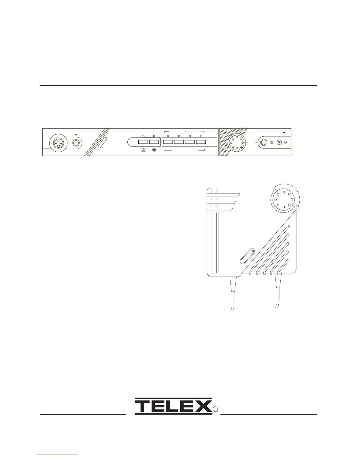
Operating Instructions
Headset
Power
X
E
L
E
T
Ext Intercom Aux Audio
RadioCom
ä
Portable Stations CarrierStatus
1
2
3
Portable Station Connect
4
Headset
Controls
Volume
X
E
L
E
T
BTR-200 II
Mic On Push Twice to Latch
PROFESSIONAL
WIRELESS
INTERCOM SYSTEM
TR-200, TR-200P,
BTR-200 II, BTR-200B II
-1-
R
Page 2

TABLE OF CONTENTS
INTRODUCTION..............................................................................................................................1
GENERAL DESCRIPTION............................................................................................................1
TR-200 BASE STATION TRANSCEIVER.....................................................................................3
TECHNICAL INFORMATION ......................................................................................................3
SPECIFICATIONS ..................................................................................................................3
FEATURES..............................................................................................................................4
CONTROLS AND CONNECTIONS..............................................................................................5
FRONT PANEL.......................................................................................................................5
REAR PANEL .........................................................................................................................6
TR-200 BELT-PACK TRANSCEIVER...........................................................................................9
TECHNICAL INFORMATION ......................................................................................................9
SPECIFICATIONS ..................................................................................................................9
FEATURES............................................................................................................................10
CONTROLS AND CONNECTIONS............................................................................................10
EXTERNAL CONTROLS ...................................................................................................10
INTERNAL CONTROLS .....................................................................................................12
EQUIPMENT SET-UP....................................................................................................................13
UNPACKING ................................................................................................................................13
ANTENNA INFORMATION .......................................................................................................13
ANTENNA CONNECTIONS ...............................................................................................13
ANTENNA POLARIZATION..............................................................................................14
DISTANCE BETWEEN ANTENNAS .................................................................................14
ANTENNA PLACEMENT ...................................................................................................15
IMPROVING RECEPTION/INCREASING RANGE..........................................................16
BTR-200 SET-UP..........................................................................................................................17
LOCATION............................................................................................................................17
INTERNAL INTERCOM SWITCHES.................................................................................17
RACK MOUNTING..............................................................................................................19
LOCAL HEADSET CONNECTION ....................................................................................21
HEADSET MIC SELECT SWITCH.....................................................................................21
TRANSMIT SWITCH...........................................................................................................21
INTERCONNECTION TO A HARD-WIRED INTERCOM...............................................22
AUXILIARY AUDIO CONNECTION.................................................................................23
POWER CONNECTION.......................................................................................................23
DUMMY LOAD....................................................................................................................23
TR-200 SET-UP.............................................................................................................................24
HEADSET CONNECTION ..................................................................................................24
DYNAMIC/ELECTRET MIC SWITCH ..............................................................................24
BATTERY INSTALLATION ................................................................................................25
-i-
Page 3

TABLE OF CONTENTS (CONT.)
PRE-WALK-THRU CHECKLIST ................................................................................................26
SYSTEM OPERATION ..................................................................................................................27
BTR-200 OPERATION .................................................................................................................27
POWER..................................................................................................................................27
LOCAL HEADSET VOLUME.............................................................................................27
PUSH TO TALK/LOCK TO TALK SWITCH......................................................................27
TR-200 OPERATION ....................................................................................................................28
POWER..................................................................................................................................28
BATTERY CHECK ...............................................................................................................28
HEADSET VOLUME ...........................................................................................................28
PUSH TO TALK/PUSH TO TRANSMIT SWITCH ............................................................28
BATTERY REMOVAL .........................................................................................................29
ENABLING AUDIO .....................................................................................................................30
PORTABLES .........................................................................................................................30
WIRED INTERCOM.............................................................................................................30
AUXILIARY..........................................................................................................................30
SETTING SYSTEM GAIN LEVELS ...........................................................................................31
ADJUSTING GAIN...............................................................................................................31
BTR-200 BASE STATION ....................................................................................................31
TR-200 PORTABLE ..............................................................................................................31
INTERCOM GAIN................................................................................................................32
AUXILIARY GAIN...............................................................................................................32
SYSTEM WALK-THRU .................................................................................................................33
TROUBLE SHOOTING .................................................................................................................34
BATTERY INFORMATION ..........................................................................................................35
GENERAL.....................................................................................................................................35
BC-4 BATTERY CHARGER........................................................................................................35
RECOMMENDED HEADSETS ....................................................................................................36
ACCESSORIES ...............................................................................................................................38
WARRANTY SERVICE INFORMATION...................................................................................40
FCC INFORMATION.....................................................................................................................41
-ii-
Page 4
INTRODUCTION
GENERAL DESCRIPTION
This manual covers the BTR-200, BTR-200II,
and the BTR-200B II Base Stations and the
TR-200 and TR-200P Portable Transceivers
(referenced as BTR-200 and TR-200 unless
otherwise specified.)
The Telex Models BTR-200 and TR-200 were
specifically designed to provide the user with a
highly flexible wireless two-way communica
tion system with the capability of interface
with a wired intercom system and other auxil
iary audio.
ANT
HEADSET
MICROPHONE
TR-200
TRANSMITTER
RF CARRIER
F
RF CARRIER
F
ANT
-
-
SIGNAL
SIGNAL
SIGNAL
SIGNAL
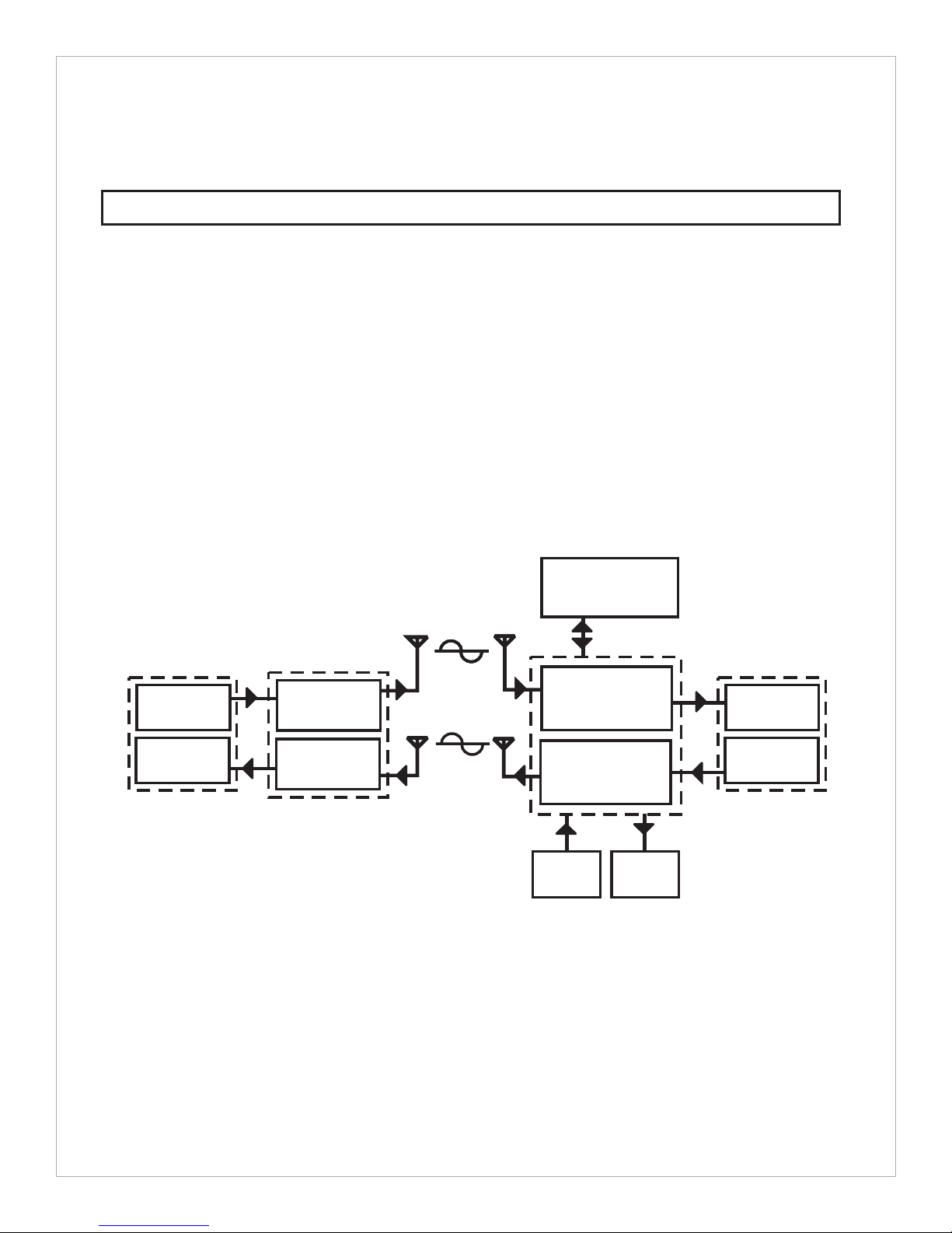
At the BTR-200 operator’s command, the
remotes may communicate with each other,
with a wired intercom system or with an auxil
iary system. The BTR-200 Base Station with
its one transmit and four receive channels was
designed to operate in full duplex (simulta
neous two-way communications) with up to
four TR-200 Belt Pack transceivers (one trans
mit and one receive channel) See block dia
gram in figure 1.
WIRED
INTERCOM
ANT
ANT
BTR- 200
HEADSET
FM
ANT
ANT
RECEIVER
REC1REC2REC3REC
4
EARPHONE
-
-
-
-
EARPHONE
RECEIVER
R CARRIER
F
SIGNAL
TRANSMITTER
AUXILIARY
INPUT
Figure 1
Block Diagram of System
-1-
AUXILIARY
OUTPUT
MICROPHONE
Page 5

The system operates on selected frequencies
within the 150-216 MHz band.
The BTR-200 system is fully compatible with
a number of other wired intercom manufactur
ers units. See the BTR-200 Setup Section for
additional information.
The Telex Model’s TR-200 and TR-200P
Belt-pack Transceivers, are designed with one
transmit and one receive channel.
The TR-200 Transceiver operates in the con
tinuous transmit mode with the audio, to talk,
activated by a switch. As many as four TR-200
belt-pack transceivers can operate in a fully
duplex network with one Telex Model
-
BTR-200 or BTR-200 II Base Station.
The TR-200P Transceiver operates in the
Push-to-transmit mode (the transmit and talk
function are activated together). Any number
of TR-200P transceivers can be used in a
half-duplex network with one BTR-200 or
BTR-200 II Base Station. Operate only one
transmitter at a time. Attempting to use two
transmitters simultaneously on the same chan
nel will cause interference.
-
-
-2-
Page 6

BTR-200 BASE STATION TRANSCEIVER
TECHNICAL INFORMATION
SPECIFICATIONS BTR-200
Input Power ........................................................................13.0 VAC RMS/300 mA with supplied adaptor
or filtered 12 to 14 VDC/300 mA source
Intercom Output ..........50 mV (Low) or 330 mV (Hi) RMS into 300 ohm load typical (at rated deviation)
Intercom Input (Gain Minimum)................................................300 mV RMS typical (for rated deviation)
Auxiliary Output ............................................430 mV RMS into 600 ohm load typical (at rated deviation)
Auxiliary Input (Gain Maximum) ................................................60 mV RMS typical (for rated deviation)
Local Headset Input .............................................................................................2 mV RMS input nominal
1.5 mV RMS input at compression (Dynamic)
Local Headset Output....................................................................32 mV maximum output into 600 ohmst
Temperature Range .......................................................................................-4°F to 130°F (-20°C to 55°C)
Dimensions....................................................................................................15.75” W x 1.75” H x 10.5” D
(40 cm x 4.5 cm x 26 cm)
Weight ......................................................................................................................................4.5 lbs (2 kg)
Transmit
RF Frequency Range...............................................................................................................150-216 MHz
RF Frequency Stability ......................................................................................Crystal Controlled, 0.005%
RF Power Output ..................................................................................................................50 mW Typical
Modulation..................................................................................................................FM, 3 KHz deviation.
115 micro-seconds Pre-emphasis
Transmit Antenna ..........................................................................................................5/8-wave (supplied)
SO239 connector on chassis
Modulation Limiter .......................................................................................................Internal Compressor
Modulation Frequency Range ...................................................................................300 to 5000 Hz ±2 dB
Radiated Harmonics and Spurious Emissions.................................................................................-45 dBC,
Exceeds FCC Specifications
FCC...................................................................................................Type Accepted Under Parts 90 and 74
-3-
Page 7

SPECIFICATIONS BTR-200 (Cont.)
Receive
RF Frequency Range..............................................................................................................150-216 MHz
RF Frequency Stability ......................................................................................Crystal Controlled, 0.005%
Type..................................................................................................Dual conversion superheterodyne, FM
RF Sensitivity.......................................................................................Less than 0.5 µV for 12 dB SINAD
IF Selectivity...............................................................................3 dB at 30 kHz (4 pole Monolythic Filter)
Image Rejection .....................................................................................................................65 dB or better
Squelch Quieting..................................................................................................................................90 dB
Squelch Threshold ..............................................................................................................1.0 µV (Internal)
Signal-to-Noise Ratio...........................................................................................................................90 dB
Receive Antenna ............................................................................................................5/8-wave (supplied)
SO239 connector on chassis
Distortion .......................................................................................................Less than 1% at Rated Output
FCC .....................................................................................................................Notification Under Part 15
FEATURES
Intercom connections with the ability to in-
The Telex Model BTR-200 is a Base Station
with one transmitter and four receivers. It is
designed for portable two way communication
with the capability for interface to other audio
systems. Features include:
·
terface with most wired intercom systems.
·
RF LED indicator for each portable station.
·
An extremely flexible unit that has the capability to communicate at one time with
any number of the available portable sta
tions (up to four) or wired stations (inter
com and/or other audio source).
·
Powered by an external AC wall supply
(supplied), via the power jack on the rear
of the unit. It can also be powered by any
filtered 12 to 14 VDC/300 mA source or
13.0 VAC RMS 300 mA source.
·
All metal case for superior shielding.
·
-
-
-4-
Molded front panel for aesthetic appeal
along with functionability .
·
Table or single height rack mountable.
Page 8
CONTROLS and CONNECTIONS
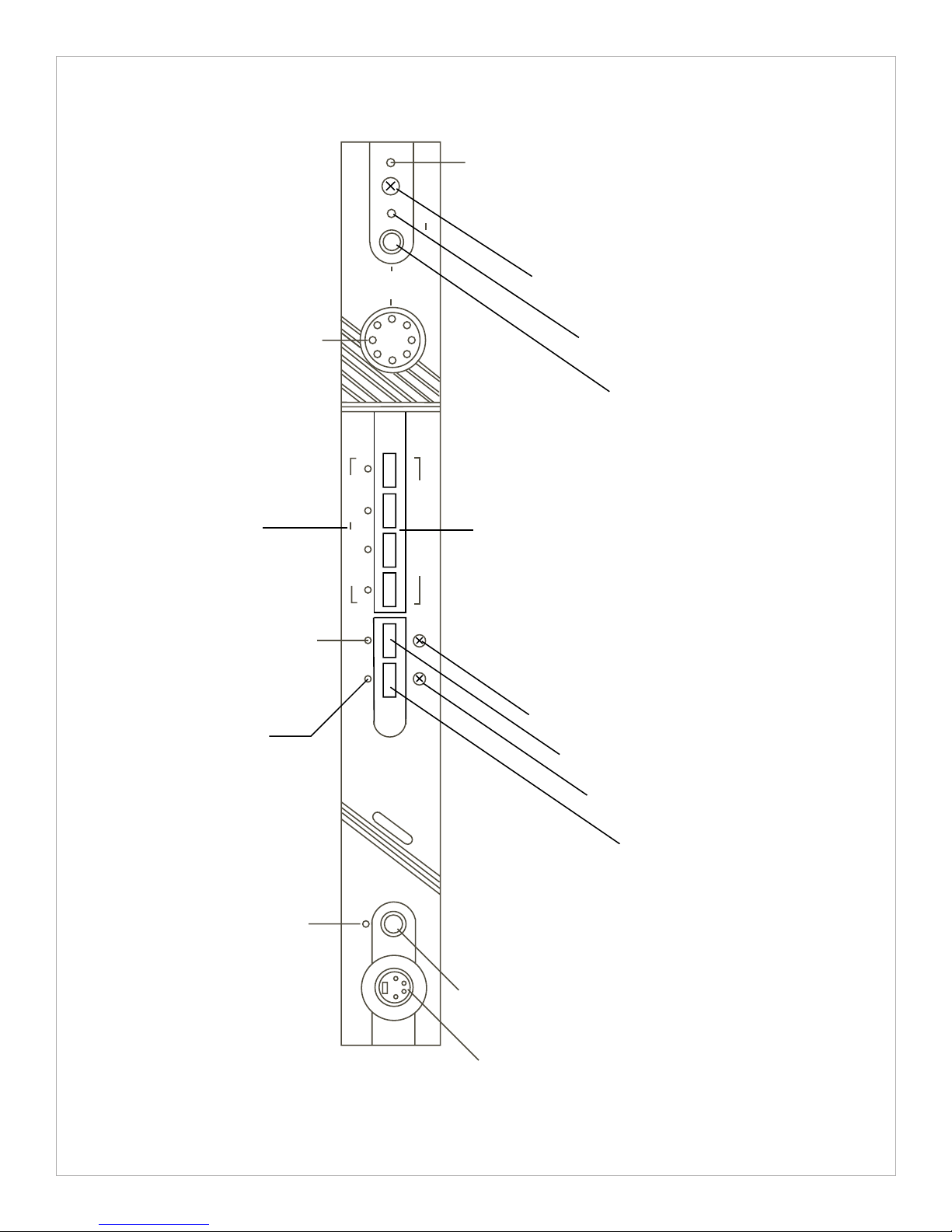
FRONT PANEL ( Refer to Figure 3)
Power ON/OFF Switch: Push this switch
once toturn power ON; push it again to turn the
power OFF.
Power ON Indicator: The Power ON Indica
tor is illuminated when the Power ON/OFF
Switch is pushed in the ON Position. It re
mains illuminated while the Transceiver ison.
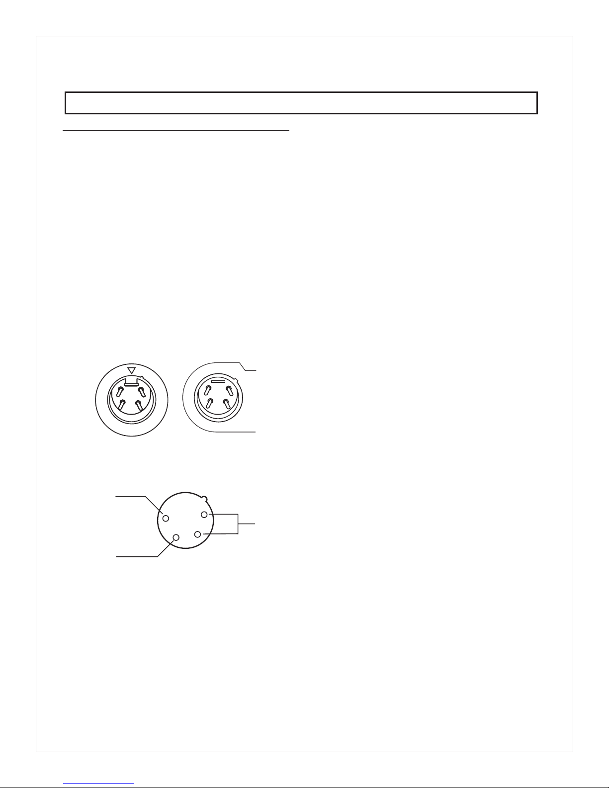
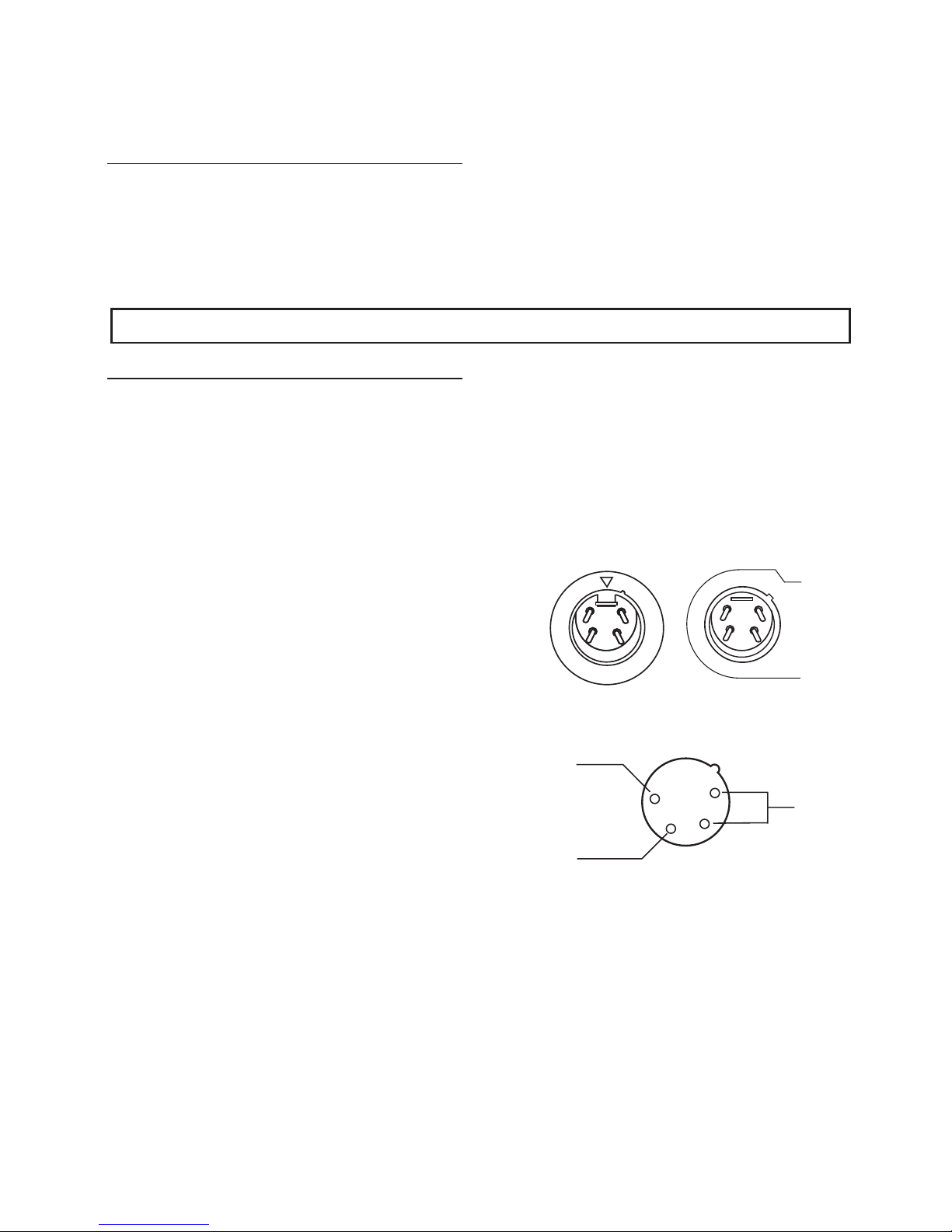
Local Headset Connector: 4 Pin XLR Con
nector for Input/Output. The headset jack will
accept 6 different Telex Model Headsets. See
“Recommended Headset” Section in back of
manual for more information. Compatible with
other intercom headsets with four pin XLR
connectors that are wired as shown in Figure 2.
MALE CONNECTORS
BTR-200/TR-200
MICROPHONE
SHIELD (-)
HEADPHONE
BALANCED
AUDIO
OUT
MICROPHONE
AUDIO (+)
1
4
3
2
Mic On-Push-to-Talk/Lock-to-Talk Switch:
Enables the local headset microphone audio
function.
NOTE: DOES NOT control base station RF
transmit.
Local Push-to-Talk Indicator: Will be illumi
nated whenever the talk function is on.
Local Microphone Gain Control and
Overmodulation Indicator: A screwdriver
adjustable control is provided to control the in
put level of the local headset mic. This input is
protected from overloads by means of a gain
compressor whoseoperation is signaled by the
gain LED indicator.
Portable Enable Switches and Indicators:
When in the “IN” position, the Enable
switches allow the user of the corresponding
portable unit to be heard by others connected
to the system. When in the “OUT” position,
the respective portable will be muted, but this
portable will still be able to hear all other selected remotes and interfaces. The indicators
normally show the presence of a portable
transceiver in use on the channel correspond
ing to that indicator.
-
-
-
Figure 2
Headset XLR Connector Wiring
Local Headset Volume: Adjusts volume to
Local Headset. DOES NOT AFFECT MICRO
PHONE GAIN.
-
-5-
Page 9

Ext Intercom Switch, Level Control, and In
dicator: This switch enables the wired inter
com interface when “IN”, and disables it when
“OUT”. For RTS intercoms, the “IN” position
is channel A and the “OUT” position is chan
nel B. A screwdriver adjustable control is pro
vided to control the input level of the wired
intercom.
Auxiliary Audio Enable Switch, Level Con
trol, and Indicator: The switch enables and
disables the Auxiliary interface when “IN” and
“OUT”, respectively. The function of the level
control here is the same as that described for
the intercom.
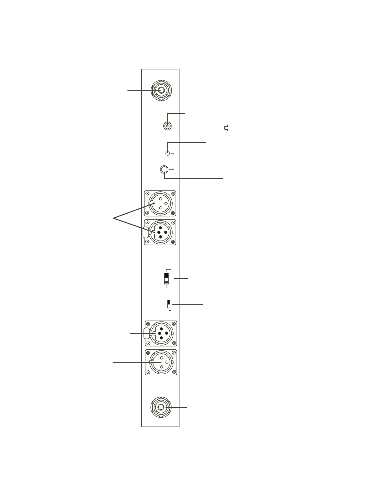
REAR PANEL (Refer to Figure 4)
Transmit Antenna Connector: Connect
5/8-wave antenna (supplied) to this connector.
Antenna color should match connector dot on
BTR-200.
Receive Antenna Connector: Connect
5/8-wave antenna (supplied) to this connector.
Antenna color should match connector dot on
BTR-200. See “Antenna Information” section
for assembly information.
Headset Microphone Select Switch: This
-
switch allows the user to select either an
Electret or Dynamic microphone. This switch
is factory preset to DYN Position.
NOTE: All Telex headsets that are used with
this intercom are dynamic type microphones.
Intercom Connectors: Connections to inter
face the BTR-200 with a wired intercom sys
-
tem.
Auxiliary Output/Input Connectors: Can be
used for 2-way (four wire) input and output to
the BTR-200 or as a simplex input or output.
Typical uses are 4 wire low level intercom’s,
tape recorders, public address inputs or out
puts, or when operating two BTR-200 units simultaneously.
Power Jack: For external AC wall supply
adaptor (supplied) or any filtered 12 to 14
VDC/300 mA source, or 13.0 VAC RMS/300
mA source.
Speaker Jack: Allows the user to connect an
external speaker (8 ohms minimum) to the
unit.
-
-
-
Transmit Switch: Slide switch that allows the
operator to select one of three transmit modes.
In the “OFF” position, the transmitter is always
off. This mode may be used if the base if func
tioning solely as a monitor. In the “CONT” po
sition, the transmitter is always on. This
continuous mode is recommended over the
“REMOTE” mode. In the “REMOTE” posi
tion, the transmitter is enabled only when one
or more portables are active.
Speaker Gain Control: Screwdriver adjust
able. Adjust the gain control clockwise to in
crease speaker gain or counterclockwise to
decrease speaker gain.
-
NOTE: Leave setting counterclockwise if no
speaker is attached.
-
-6-
-
-
Page 10
BTR-200 II
LOCAL HEADSET VOLUME
INDICATOR
LOCAL MIC
OVERMODULATION
Mic On Push Twice to Latch
Headset
Controls
Volume
LOCAL MIC GAIN CONTROL
LOCAL PUSH-TO-TALK INDICATOR
MIC ON PUSH-TO-TALK/
LOCK-TO-TALK SWITCH
4
3
PORTABLE CARRIER INDICATORS
AUXILIARY ENABLE
INTERCOM
INDICATOR
POWER ON
INDICATOR
Portable Stations Carrier Status
Aux Audio
2
1
Portable Station Connect
ENABLE SWITCHES TO RECEIVE
PORTABLE TRANSMITTERS
Figure 3
INDICATOR
Ext Intercom
Front Panel BTR-200
AUXILIARY LEVEL CONTROL
AUXILIARY ENABLE SWITCH
X
E
L
E
T
INTERCOM LEVEL CONTROL
INTERCOM ENABLE SWITCH
Power
Headset
POWER ON-OFF SWITCH
LOCAL HEADSET CONNECTOR
-7-
Page 11
RECEIVE
Receive Antenna
INTERCOM CONNECTORS
ANTENNA CONNECTOR
TELEX COMMUNICATIONS, INC.
FCC I.D. B5DBTR-200 MADE IN U.S.A..
Intercom
Intercom
PUSH
Intercom
Power
Loop-Thru
Loop-Thru
Input
Transmit
Gain
Jack
300 mA
AC/DC 13.O.V.
Speaker
Remote
Off
Cont
Elt
MIN.)
POWER JACK
SPEAKER GAIN CONTROL
SPEAKER / LOCAL MONITOR ( 8
Figure 4
Rear Panel BTR-200
TRANSMITTER SWITCH
AUXILIARY OUTPUT CONNECTOR
AUXILIARY INPUT CONNECTOR
Auxiliary
PUSH
Transmit Antenna
Audio Input
Headset Mic
Auxiliary
Dyn
Audio Output
TRANSMIT ANTENNA
CONNECTOR
-8-
HEADSET MIC SELECT SWITCH
Page 12

TR-200 BELT-PACK TRANSCEIVER
TECHNICAL INFORMATION
SPECIFICATIONS TR-200
Overall
Power Requirements ......................................................................6AA cells (Alkaline, NEDA, MN 1500)
Nickel Cadmium Optional
Current Drain ..........................................................................................................................typical 65 mA
Temperature Range .......................................................................................-4°F to 130°F (-20°C to 55°C)
Dimensions......................................................................................................4.25” W x 4.125” H x 2.0” D
(108mm x 105mm x 51 mm)
Weight.................................................................................................................13 oz (369g) with batteries
Transmit Antenna...................................................................................................1/4-wave wire (attached)
Receive Antenna ....................................................................................................1/4-wave wire (attached)
Transmit
RF Frequency Range...............................................................................................................150-216 MHz
RF Frequency Stability ......................................................................................Crystal Controlled, 0.005%
RF Power Output ..................................................................................................................50 mW Typical
Modulation ..............................................................................................................FM, 5000 Hz deviation,
115 micro-seconds Pre-emphasis
Modulation Limiter .......................................................................................................Internal Compressor
Modulation Frequency Range................................................................................300 to 5000 Hz +/_2 dB
Microphone Audio Input.....................................................................................................30 to 3500 ohms
Microphone Input Sensitivity .......................................................................2 mV Dynamic, 4 mV Electret
Radiated Harmonics and Spurious Emissions.................................................................................-45 dBC,
Exceeds FCC Specifications
FCC...................................................................................................Type Accepted Under Parts 90 and 74
RF Frequency Range...............................................................................................................150-216 MHz
RF Frequency Stability.............................................................................Crystal Controlled, 0.005% Type
RF Sensitivity........................................................................................Less than 0.5 µV for 12 dB SINAD
IF Selectivity...............................................................................................3 dB at 30 kHz (Ceramic Filter)
Image Rejection .....................................................................................................................70 dB or better
Squelch Quieting..................................................................................................................................90 dB
Squelch Threshold ..............................................................................................................3.0 µV (Internal)
Signal-to-Noise Ratio...........................................................................................................................90 dB
Audio Output .............................................................................................32 mW into 600 ohms (Headset)
Distortion .......................................................................................................Less than 1% at Rated Output
FCC .....................................................................................................................Notification Under Part 15
Receive
Dual Conversion Superheterodyne, FM
-9-
Page 13
FEATURES
Lightweight, small size and is
·
self-contained.
2 separate antennas, one for transmit, the
·
other for receive.
CONTROLS AND CONNECTIONS
Push-to-Talk with Lock-to-Talk feature
·
switch for the TR-200 and
Push-to-Transmit with Lock-to-Transmit
feature for the TR-200P.
EXTERNAL CONTROLS (Refer To Figure 6)
Volume OFF/ON Control: This thumbwheel
control serves as both an off/on switch and as a
volume control.
Low Battery and Overmodulation Indicator
LED:
Low Battery Indicatorœ: Part of the battery check circuit. When the power switch is
placed in the “ON” position the LED will
flash one time if the battery is good. A poor
battery will cause the LED to illuminate
continuously and a bad or unusable battery
will not cause any illumination at all.
Overmodulation Indicator: Uses the same
LED as the low battery indicator. During the
talk mode, if the microphone gain is too
high, the LED will illuminate when talking.
Push-To-Talk/Lock-To-Talk Switch: For
Model TR-200, this switch enables the talk
function. For Model TR-200P, this switch en
ables the transmit and audio function and oth
erwise operates as described for TR-200.
Headset Jack: A four pin XLR connector for
Input/Output. The headset jack will accept six
different Telex Model Headsets. See “Recom
mended Headset” Section for more informa
tion. Compatible with other intercom headsets
with four pin XLR connectors that are wired as
shown in Figure 5.
MALE CONNECTORS
BTR-200/TR-200
MICROPHONE
SHIELD (-)
4
3
2
-
-
MICROPHONE
AUDIO (+)
1
HEADPHONE
BALANCED
AUDIO
OUT
-
-
Talk LED Indicator: (Labeled “talk”) Will be
illuminated whenever the talk function on the
TR-200 or transmit function on the TR-200P is
enabled.
Figure 5
Headset XLR Connector Wiring
-10-
Page 14
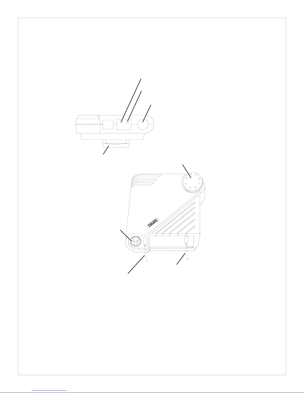
LOW BATTERY / OVERMODULATION
INDICATOR LED
TALK LED INDICATOR
PUSH-TO-TALK/
LOCK-TO-TALK SWITCH
bat/
ovmod
BELT CLIP
HEADSET JACK
talk
talk
VOLUME OFF/ON CONTROL
R
RECEIVE ANTENNA
TRANSMIT ANTENNA
Figure 6
External Controls, TR-200
-11-
Page 15

DYNAMIC / ELECTRET
ACCESS TO MICROPHONE
SWITCH
FCC ID: B5DTR200
S/N:
P/N:70681-
BATTERY COMPARTMENT
MADE IN U.S.A.
MIC
E
GAIN CONTROL
D
INTERNAL CONTROLS (Refer To Figure 7)
Belt Clip: Combination Belt Clip/Battery
Cover. Access to Battery Compartment, Micro
phone Gain Control and Dynamic/Electret
Switch is accomplished by removal of belt clip
via a quick release 1/4 turn fastener.
Microphone Gain Control: Screwdriver ad
justable by removing belt clip and prying out
the small rubber plug to the right of the screw
boss.
Figure 7
Internal Controls, TR-200
Dynamic/Electret Switch: This switch allows
selection of “D” when using a Dynamic Micro
phone or "E" when using an Electret Micro
-
phone.
NOTE: All Telex headsets that are used with
this intercom are dynamic microphones. Unit
is shipped in the “D” position.
-
Battery Compartment: Holds 6 AA batteries
in a removable battery holder (supplied).
-12-
-
-
Page 16

EQUIPMENT SET-UP
UNPACKING
Unpack your BTR-200 and TR-200 System. If
there are any damages or shortages, refer to the
“Warranty Service Information" section in this
manual.
ANTENNA INFORMATION
ANTENNA CONNECTIONS
The BTR-200 is supplied with two (2) anten
nas. One 5/8-wave antenna for Transmit and
one 5/8-wave for Receive.
To insure that the frequency range of the anten
nas match the receiver and transmitter of the
BTR-200, match the color code on the antenna
with the color code on the BTR-200.
-
Assemble the 5/8-wave antenna by screwing
the three sections into one another as shown in
Figure 8. All three sections of the BTR-200
5/8-wave antennas must be used. Leaving out a
section will result in reduced distance capability.
DO DON’T
Attach the receive 5/8-wave antenna to the antenna input receptacle labeled “Receive Antenna” on the right side of the rear panel via
the supplied connectors. Attaching the angled
connector to the base station receptacle first,
then attaching the straight connector, as shown
in Figure 9, will prevent antenna sway.
Figure 8
5/8-wave Antenna Assembly
Figure 9
Attaching 5/8-wave Antenna
-13-
Page 17

Attach the transmit 5/8-wave antenna to the
antenna input receptacle labeled “Transmit An
tenna” on the left side of the rear panel. The
antenna should be vertically aligned.
DISTANCE BETWEEN ANTENNAS
The distance between the BTR-200 Receive
and Transmit antennas is not adjustable when
the antennas are connected directly on the back
of the unit.
The antennas can be remoted for better signal
path. A Telex coax assembly is required. See
“Accessory” section for order information.
NOTE: If your BTR-200 transceiver is to be
located in a shielded rack mount enclosure or
other poor RF location, you must remote the
5/8-wave antennas with coax assemblies.
Figure 10
Transmit Antenna Receptacle
ANTENNA POLARIZATION
The Telex Wireless Intercom System is “Vertically Polarized". This means both the transmit-
ting and receiving antennas should operate in
the vertical position.
Headset
E
L
E
T
Power
X
E
L
E
T
PortableStations Carrier Status
ExtIntercom Aux Audio
4
2
1
X
PortableStationConnect
3
BTR-200II
Headset
Controls
Volume
MicOn PushTwiceto Latch
Figure 11
Vertically Polarized Antennas
-14-
Page 18

ANTENNA PLACEMENT
Proper antenna placement probably has the
most effect on your TELEX Wireless Intercom
System’s overall performance. The following
suggestions will result in optimum perfor
mance.
Proper placement of the TR-200 can be criti
cal. The trailing antennas should “dangle”
freely. “Wadding” the antennas up and placing
the TR-200 in a pocket, etc., will reduce sys
tem distance.
It is suggested that the unit be worn on the belt
or pocket with both antenna’s hung vertically
for best operating range and performance.
Keep the distance between the base (BTR-200)
and the belt packs (TR-200) antennas as short
as possible. The greater the distance, the
weaker the signal. However, the portables
should be a minimum distance of 10 feet from
the base station and each other for best perfor
mance.
-
X
E
L
E
T
-
700 FEET
Headset
PortableStations CarrierStatus
ExtIntercom AuxAudio
1
X
E
L
E
T
PortableStationConnect
Power
X
E
L
E
T
100 FEET
BTR-200II
4
2
3
Headset
Controls
Volume
MicOnPush Twice to Latch
AS DISTANCE INCREASES, SIGNAL
STRENGTH
DECREASES
Figure 13
Distance Between BTR-200 and TR-200
-
X
E
L
E
T
Figure 12
Proper Dressing of the Antennas
Make sure the “signal paths” between the
BTR-200 and remotes are unobstructed. You
should always be able to visibly locate the an
tennas at all times, for best performance.
X
E
L
E
T
Headset
X
E
L
E
T
SIGNAL REACHES
ANTENNA AT FULL
STRENGTH WITH NO
OBSTRUCTIONS
PortableStations CarrierStatus
ExtIntercom AuxAudio
4
2
1
3
X
E
L
E
T
Power
PortableStationConnect
Volume
Figure 14
Keeping Site Clear to Antenna
-15-
-
BTR-200II
Headset
Controls
MicOn Push Twice to Latch
Page 19

Attempting to operate the wireless intercom
system through or around walls, ceilings, metal
objects, etc. will reduce system range and per
formance.
DO NOT - mount the BTR-200 5/8-wave an
tennas on, or next to, metal such as beams,
-
walls with metal studs, equipment racks, etc.
This also applies to the antennas when assem
bled directly to the BTR-200. This will “de
tune” the receiving antenna which can result in
noise or loss of RF signal at the BTR-200. See
Figure 16.
-
-
-
Headset
PortableStations CarrierStatus
ExtIntercom AuxAudio
1
X
E
L
E
T
Power
BTR-200II
4
2
3
Headset
Controls
PortableStationConnect
Volume
MicOn Push Twice to Latch
SIGNAL REFLECTION OFF A METAL OBSTRUCTION
CAUSES REDUCED SIGNAL AND “MULTIPATH”
Figure 15
Operating System Near Obstructions
1. Placing the unit on top of a
2. Placing the unit on top of a
shelf or equipment rack and
remoting the receive antenna
is OK.
1
IMPROVING RECEPTION AND IN
CREASING RANGE
X
E
L
E
T
Keeping the distance from the base (BTR-200)
and the belt packs (TR-200) as short , and un
obstructed as possible will produce the most
reliable performance.
The BTR-200 is supplied with two antennas.
This should provide satisfactory system performance in most applications. System range can
be enhanced by remoting the 5/8-wave receive
antenna.
shelf or equipment rack unobstructed without remoting
the receive antenna is OK.
2
-
-
3. Placing the unit on top of
a shelf or equipment rack
and mounting the
remoted receive antenna
on the side of the shelf or
equipment rack is BAD.
3-BAD
Headset
PortableStations CarrierStatus
ExtIntercom AuxAudio
4
1
2
3
X
E
L
E
T
Power
Headset
Controls
PortableStationConnect
Volume
MicOn Push Twice to Latch
BTR-200II
Headset
Power
PortableStations CarrierStatus
ExtIntercom AuxAudio
1
X
E
L
E
T
BTR-200II
4
2
3
Headset
Controls
PortableStationConnect
Volume
MicOn Push Twice to Latch
Headset
Power
PortableStations CarrierStatus
ExtIntercom AuxAudio
1
X
E
L
E
T
PortableStationConnect
BTR-200II
4
2
3
Headset
Controls
Volume
MicOn Push Twice to Latch
Figure 16
Receive Antenna Placement
-16-
Page 20

BTR-200 SET-UP
LOCATION
Locate the BTR-200 transceiver on a level sur
face with the rear of the unit facing you. See
“Antenna Information” section for more infor
mation on choosing a location.
INTERNAL INTERCOM SWITCHES
Intercom Dip Switch: Located in the inside of
the unit is a DIP Switch. This switch will have
to be set for the wired intercom unit you will
be using. The switch is factory set for interfac
ing with Telex Audiocom wired intercom
units. See Table 1 if you will be using an RTS
or Clearcom wired intercom system.
SWITCH POSITION
123456789
Telex Audiocom ON ON OFF ON OFF ON OFF OFF ON
To change the switch positions you will need
to remove the cover on the BTR-200. Remove
three #6-32 x 3/8" screws on both sides of the
unit. Remove four #4-40 x 3/16" screws on the
top front and loosen three #4-40 x 3/16"
screws on the back of the unit. The cover will
slide off.
Reference Figure 17 for switch positions.
Change the switch positions as indicated in the
-
chart depending on the wired intercom system
you will be using. After setting this switch, set
the High/Low switch as shown in the next sec
tion and then replace cover and secure with the
hardware previously removed.
-
RTS OFF OFF ON OFF ON OFF ON ON OFF
Clearcom ON OFF ON ON OFF OFF OFF ON ON
Table 1
Dip Switch Positions For Wired Intercom Terminations
9
FRONT
O
F
R
Figure 17
Dip Switch
N
O
3
2
1
N
T
8
7
6
5
4
-17-
Page 21

High/ Low Switch: Along with setting the
DIP switch inside the unit to correspond to the
wired intercom you have selected to use, you
must also set the “High/Low” switch. This
switch is also located inside the BTR-200 as
shown in Figure 18.
Switch See
Setting Detail
Telex
AudioCom High A
RTS High A
For the correct setting corresponding to your
wired intercom unit see Table 2. The switch is
factory set for use with Telex AudioCom or
RTS wired intercoms.
SEE DETAIL A AND B
LOW
HIGH
Clearcom Low B
Table 2
HIGH
LOW
Detail A
High Setting
FRONT
HIGH
Figure 18
Location of High/Low Switch
-18-
LOW
Detail B
Low Setting
Page 22

RACK MOUNTING
Install BTR-200 in Rack Enclosure: To rack
mount the BTR-200 base transceiver do the
following:
Place the rack mount brackets (supplied) on ei
ther side of the unit and insert three #6-32 x
3/8" screws for each bracket. Tighten the
screws securely.
-
Remove the two #6-32 x 3/8" screws on each
side of the transceiver as shown in Figure 19.
X
E
L
E
T
Insert the BTR-200 into your 19" rack enclo
sure and insert four (4) #10-32 x 3/8" Phillips
pan head screws (supplied) in each corner of
the rack mount brackets and secure to your en
closure.
REMOVE SCREWS
(TYPICAL BOTH SIDES)
-
-
Attaching Brackets For Rack Mounting
#6-32X3/8
Figure 19
-19-
Page 23

Remoting Antennas: It will be necessary to
remote both the transmit and receive antennas
on the BTR-200 when it is rack mounted.
Connect the coax cable assembly (not sup
plied), to the back of the receive antenna re
ceptacle and remote the 5/8-wave antenna. The
antenna can be attached to either a wall mount
bracket or a microphone stand bracket (not
supplied). See “Accessory” section for order
information.
You will also need to remote the transmit an
tenna in the same manner. Connect a coax ca
ble assembly to the transmit antenna
receptacle. Remote the 5/8-wave antenna, by
attaching the antenna to one of the brackets
(not supplied).
-
-
-
Headset
X
E
L
E
T
Power
ExtIntercom Aux Audio
PortableStations Carrier Status
1
PortableStationConnect
4
2
3
BTR-200II
Headset
Controls
Volume
MicOn PushTwiceto Latch
Remoting Antennas When Rack Mounted
Figure 20
-20-
Page 24

LOCAL HEADSET CONNECTION
Insert the headset/microphone into the 4 pin
XLR connector on the front panel. See the mi
crophone connection diagram (Figure 2) if
other than a Telex Headset is used.
HEADSET MICROPHONE SELECT
SWITCH
If the headset you are using has an Electret mi
crophone, the local microphone select switch
must be in the “ELT” position (Electret). This
switch is located on the rear panel. A +5 volt
bias is available at the microphone plug for
electret use.
-
TO HEADSET
OR HANDSET
X
E
L
E
T
Figure 21
-
Connecting Headset to the BTR-200
Headset Mic
If you are using a headset with a dynamic mi
crophone, place the local microphone select
switch in the “DYN” position (Dynamic).
NOTE: FOR PROPER OPERATION YOU
MUST MATCH THE TYPE OF MICRO-
PHONE YOU ARE USING WITH THE DYNAMIC/ELECTRET SWITCH LOCATED
ON THE REAR OF THE UNIT.
TRANSMIT SWITCH
Allows the operator to select three different
types of transmitting modes; continuous trans
mitter, transmitter off, or remote transmitter.
For most operations, place the transmitter
switch in the “CONT” position (Continuous
mode).
In the Continuous mode the transmitter
therefore will be on at all times regardless of
whether the portables are on or not.
-
Dyn
Elt
Figure 22
Headset Microphone Select Switch
-
Transmit
Cont
Off
Remote
In the Remote mode, the only time the base
can transmit is when a portable unit is turned
on.
In the Off mode the BTR-200 base station
will not transmit to the remote belt-packs.
This mode might be used if the base is to be
a monitor station only.
Figure 23
Transmit Switch
-21-
Page 25

INTERCONNECTION TO A HARD-WIRED
INTERCOM SYSTEM
The RADIOCOM wireless system can be inte
grated into Telex intercom systems and most
existing wired intercom systems including RTS
and Clearcom.
EXTERNAL
SPEAKER
Connect the intercom cable to the back of the
BTR-200. There are two intercom connections
on the back of the unit, one being a male con
nector, the other a female connector, connected
in parallel with each other. Either works as an
input or output.
BINAURAL
BELTPACK
BINAURAL
BELTPACK
-
LOCAL MONITOR
BELTPACK
Headset
X
E
L
E
T
Power
INTERCOM
ExtIntercom Aux Audio
PortableStations Carrier Status
2
1
PortableStation Connect
IN OUT
3
AUX
4
BTR-200 II
Headset
Controls
Volume
BTR-200
MicOn PushTwiceto Latch
PA SYSTEM
ANOTHER BTR 200
OR OTHER AUDIO INPUT
TR-200 TR-200
X
E
L
E
T
X
E
L
E
T
TR-200
X
E
L
E
T
TR-200
X
E
L
E
T
Figure 24
Typical Interface to Wired System
-22-
Page 26

PUSH
XXXX
XXXX
PUSH
I/C
PUSH
XXXX
XXXX
Figure 25
Connecting Two BTR-200 Together
CONNECTING AUXILIARY AUDIO SYSTEM
Connect the BTR-200 to your auxiliary audio
via the Auxiliary input/output receptacles on
the rear of the unit or when two BTR-200 are
used as a system.
Connect the first BTR-200 to the second
BTR-200 by using two short male to female
XLR type cables (not supplied). See Figure 25.
Note that the stations need to be on different
frequencies.
POWER CONNECTION
PUSH
I/C
DUMMY LOAD
In the case where a wired intercom will not be
used with the BTR-200, it is important that the
dummy load (supplied) be installed. The
dummy load should be plugged into the “Intercom Loop-Thru” connector.
NOTE: If this is not set up properly, an annoy
ing squeal may result that may cause damage
to the ears.
POWER
AC/DC 13 OV 300mA
BTR 200
-
Insure the Power ON/OFF Switch on the front
of the BTR-200 is in the “OFF” position. Con
nect the supplied AC power supply cord to the
receiver at the socket labeled “POWER”. Con
nect the power supply unit to an AC outlet sup
plying 105 to 125 VAC, 60 Hz.
-
-
-
-23-
TO
AC
OUTLET
U
Figure 26
Connecting the Power Supply
Page 27

TR-200 SET-UP
HEADSET CONNECTION
Insert the headset/microphone into the connec
tor on the bottom of the unit. See the headset
connection diagram (Figure 5) if unit other
than Telex is used.
R
TO HEADSET
DYNAMIC/ELECTRET SWITCH
If the headset you are using has an Electret mi
crophone, the dynamic/electret switch must be
in the “E” position (Electret). This switch is
accessible by removing the belt clip and re
moving the battery holder. A +5 volt bias is
available at the microphone plug for electret
use.
If you are using a headset with a dynamic mi
crophone, place the dynamic/electret switch in
the “D” position (Dynamic).
NOTE: FOR PROPER OPERATION YOU
MUST MATCH THE TYPE OF MICROPHONE YOU ARE USING WITH THE DYNAMIC/ELECTRET SWITCH LOCATED
INSIDE THE BATTERY COMPARTMENT.
-
-
-
Figure 27
Connecting Headset
FCC ID: B5DTR200
S/N:
P/N:70681-
ELECTRET DYNAMIC
MADE IN U.S.A.
MIC
E
D
Figure 28
Dynamic/Electret Switch
-24-
Page 28

BATTERY INSTALLATION
Insure that the OFF/ON Volume control knob
is turned OFF. Access the battery compartment
by removing the belt clip on the back of the
unit. Release the 1/4 turn fastener located on
the back of the belt clip and remove belt
clip/cover.
REMOVE BELT CLIP
Remove the battery holder from the box. Insert
six (6) AA batteries in the holder, paying close
attention to polarities of the batteries.It may be
necessary to turn the batteries with the thumb
and forefinger the first few times the batteries
are inserted into the battery holder to insure
good positive contact. Insert the holder into the
case and replace the belt clip/battery cover and
engage the 1/4 turn fastener.
Figure 29
Battery Installation
-25-
Page 29

PRE-WALK-THRU CHECKLIST
Following the instructions fully to this point
you have successfully competed the following
checklist:
Set internal intercom switch to cor
respond with the wired intercom.
Located the BTR-200 transceiver
properly.
Connected power to BTR-200 trans
ceiver.
Connected the 1/4-wave and
5/8-wave antenna to the BTR-200.
Check frequency range of the antenna matching the frequency of the
BTR-200 by correctly matching
color codes.
Set Dynamic/Electret switches in
both BTR-200 and TR-200
Set transmit switch on BTR-200.
-
-
If you missed any of the above instructions, go
back and complete that instruction before going on.
Connected headsets to BTR-200 and
all TR-200’s
Connected the BTR-200 to any
auxiliary audio, intercom or exter
nal speaker.
Installed batteries in the TR-200
Remote Transceiver.
-
-26-
Page 30

SYSTEM OPERATION
BTR-200 OPERATION
POWER
If you have followed the instructions until this
point, you should now be ready to turn both the
TR-200 and the BTR-200 “ON”.
Place the power switch on the BTR-200 in the
“ON” position. The red power on indicator
LED should illuminate.
OFF
Figure 30
Power ON/OFF - Volume Control Knob
LOCAL HEADSET VOLUME
Adjust the volume control on the BTR-200 by
rotating theVolume control either clockwise or
counterclockwise as required for comfortable
listening volume.
INCREASES
VOLUME
Volume
LOCAL HEADSET VOLUME
Figure 31
Volume Control - BTR-200
PUSH TO TALK/LOCK-TO-TALK SWITCH
To enable the talk function on the BTR-200,
press and hold down on the talk button and begin talking. Releasing the talk button will discontinue the microphone audio. For
continuous talk, quickly press the talk button
twice. This enables the talk function as long as
you want. To release the talk function press the
talk button once more and the talk function
will cease.
NOTE: The talk LED will be illuminated
whenever the talk function is activated.
TALK LED
BTR-200 II
Mic On Push Twice to Latch
PUSH TO TALK
LOCK TO TALK SWITCH
Figure 32
Push-to-Talk/Lock-to-Talk Switch
-27-
Page 31

TR-200 OPERATION
POWER
You should now be ready to turn the TR-200
“ON”. Rotate the OFF/ON Volume Control
Switch on the TR-200 counterclockwise to turn
the unit on.
BATTERY CHECK
As you rotate the OFF/ON Volume Control
knob clockwise to turn the unit on, note that
the battery LED (labeled bat/ovmod) should
flash one time on good batteries. Poor batteries
will cause the LED to be illuminated continu
ously and a bad or unusable battery will not
cause any illumination at all.
bat/
talk
ovmod
PUSH TO TALK/PUSH TO TRANSMIT
To enable the talk function on the Model
TR-200 press and hold down on the talk button
and begin talking. Releasing the talk button
will discontinue the microphone audio. For
continuous talk, quickly press the talk button
twice. This locks on the talk function. To re
lease the talk function press the talk button
once. Note that the TR-200 transmits any time
that the power is on.
-
For the Model TR-200P, the switch enables
both the transmit and audio functions and oth
erwise operates as described for the TR-200.
NOTE: The talk LED will be illuminated
whenever the talk function is activated.
-
-
Figure 33
Low Battery andOvermodulation
Indicator LED
HEADSET VOLUME
After batteries have been checked, adjust the
volume control by rotating the control as re
quired for comfortable listening volume.
ON/ INCREASES
VOLUME
ON / OFF SWITCH AND
VOLUME CONTROL
X
E
L
E
T
Figure 34
Power ON/OFF - Volume Control -TR-200
talk
talk
PUSH-TO-TALK/LOCK-TO-TALK SWITCH
-
Figure 35
Push-to-Talk/Lock-to-Talk Switch
-28-
Page 32

BATTERY REMOVAL
To remove the battery holder from the case to
change batteries, follow the instructions as be
fore for removing the cover. Pull the pull-bale
strap on the holder, the holder should come
out. Some models will not have the pull bale.
If the pull bale is not present on the battery
holder, turn the unit over with the battery
holder facing downward. Give the case a slight
shake into the palm of your hand, the holder
should fall out.
REMOVE BELT CLIP
NOTE: For maximum uninterrupted service it
is suggested that new 1.5 volt alkaline AA bat
teries (Mallory MN1500 or equivalent) be in
stalled prior to each use. Avoid “shelf worn” or
“economical” batteries. Operation from heavy
duty nickel-cadmium batteries is also permissi
ble, at the expense of operating time. (NEDA
10015 or equivalent). Typical life of fresh alka
line batteries with the TR-200 is approximately
24 hours maximum, 8-10 hours is typical of
fully charged nickel-cadmium batteries.
NOTE: Nickel-cadmium batteries can be
charged right in the holder using the Telex
BC-4 Battery Charger. Refer to “Battery Infor
mation” Section.
-
-
-
-
-
Figure 36
Battery Removal
-29-
Page 33

PORTABLE TRANSCEIVERS
ENABLING AUDIO
Select the TR-200 portables that will be on line
with the BTR-200. Push in the portable enable
switches that correspond to the frequencies of
the TR-200 remotes that you will be using. The
frequencies of the portable stations 1,2,3, and
4, are listed on the bottom of the BTR-200.
The Portable Carrier LED will illuminate when
the remote on that frequency is turned on. The
indicators may also light in response to outside
interference on that channel or to
intermodulation arising from portables being
used at too close a distance to the base. To pre
vent these sources from creating undesirable
noise, all unused channels should be switched
out.
INTERCOM SWITCH
The intercom switch in the front of the unit
will act as an enabling switch when the unit is
being used with either a Telex Audiocom wired
intercom or Clearcom wired intercom.
When using a RTS system wired intercom the
switch will act as a channel selector switch for
selecting of either Channel A or Channel B.
AUXILIARY
The AUX Switch on the front of the BTR-200
will enable any auxiliary audio that will be
used.
-
Ext Intercom Aux Audio
Enable Switches
Portable Stations Carrier Status
1
Portable Station Connect
Figure 37
-30-
2
3
4
Page 34

SETTING SYSTEM GAIN LEVELS
ADJUSTING GAIN
The gain may need to be adjusted for various
audio conditions. The overmodulation LED
will indicate when the gain is too high. If the
LED is illuminated when you are talking, the
gain is too high and will need to be decreased.
If the LED does not flash at all, and the audio
is low, the gain may need to be increased. An
occasional flash of the overmodulation indica
tor is fine.
If the transmitted audio is too high or to low,
the gain control potentiometer will need to be
adjusted. Using a plastic screwdriver (sup
plied), adjust the control clockwise to increase
the gain or counterclockwise to decrease the
gain. Note that the gain can also be adjusted by
changing the spacing between the microphone
and your mouth.
BTR-200 BASE STATION
The microphone overmodulation indicator for
the BTR-200 headset can be found on the right
side of the front panel. The microphone gain
control potentiometer is located to the left of
the indicator.
TR-200 PORTABLE
The overmodulation circuitry in the TR-200
uses the same LED as the low battery circuitry.
If modulation is too high this LED will illumi
nate when talking.
If the gain needs to be adjusted, remove the
belt clip on the rear of the unit and pry out the
small rubber plug to the right of the screw
boss. This will reveal the microphone gain
control potentiometer. Once adjusted, replace
the rubber plug.
-
INCREASE
TELEX
BTR-200 II
DECREASE
Mic On Push Twice to Latch
OVERMODULATION
INDICATOR
REMOVE BELT CLIP
Figure 38
Adjusting Microphone Gain -BTR-200
INCREASE
DECREASE
GAIN
CAUTION
DO NOT remove
this plug or attempt
to adjust. This beltpack
has been precisely tuned
and any attempt to alter
this adjustment will result
in a non-operational unit.
REMOVE THIS RUBBER
PLUG FOR ACCESS TO
THE MICROPHONE GAIN
CONTROL
Figure 39
Adjusting Microphone Gain -TR-200
-31-
Page 35

INTERCOM GAIN
AUXILIARY GAIN
If the audio volume, at the intercom, is too
high, the LED will be illuminated when the
person on the intercom is talking. Decrease the
gain until the LED does not illuminate while
talking at normal volume. Occasional flashing
of the LED is allowable.
OVERMOD
INDICATORS
If the audio volume, at the auxiliary output, is
too high, the Aux LED will be illuminated
when the person on the auxiliary is talking.
Decrease the auxiliary gain until the auxiliary
LED does not illuminate while talking at nor
mal volume. Occasional flashing of the auxil
iary LED is allowable. The auxiliary indicator
has three states: OFF, HALF BRIGHT, AND
FULL BRIGHT. When the switch is “OUT”,
the indicator is OFF. When the switch is “IN”
it becomes HALF BRIGHT, and when the in
put compressor operates it becomes FULL
BRIGHT.
-
-
-
Ext Intercom Aux Audio
GAIN
CONTROLS
Figure 40
Auxiliary Gain Controls
-32-
Page 36

SYSTEM WALK-THRU
Now that you have successfully “set up” your
TELEX Wireless Intercom System and turned
on any auxiliary equipment you are ready to
test the overall performance by “Walking” the
TELEX system through the areas in which you
will be using it.
Before you begin your walk-thru check the fol
lowing:
TR-200 Battery Check.
Set microphone gain in both the TR200 and the BTR-200.
Check the push-to-talk switch is
engaged in the Lock-to-talk position.
LED will be illuminated.
Only portable units to be used are enabled at the Base.
The “system walk-thru” can detect problems of
weak signal strength caused by:
Under normal conditions the portable carrier
indicator LEDs on the BTR-200 should always
be lit when portables are transmitting. “Weak
Signal” conditions will result in flashing of the
Carrier LED.
In 99% of all instances you will set up your
TELEX Wireless Intercom System, walk it
through and achieve error-free performance. If
in the rare instance your TELEX System does
not “pass” during your walk-thru evaluation,
refer to the last section of this manual which
deals with System Troubleshooting.
·
Poor antenna location
·
Wrong antenna for receiver and/or trans
mitter.
·
RF “Trouble Spots”
·
Operating distance beyond system
capability.
·
Old or used batteries in the TR-200
-
-33-
Page 37

TROUBLESHOOTING
Reread the sections of this manual to make sure
you have completed system set-up properly
PROBLEM SOLUTION
DISTORTION - System’s audio quality
seems distorted at medium to high input lev
els.
HISS - System seems to produce a “hiss”
which is undesirable.
LOW OUTPUT - System produces a low
output level.
FEEDBACK - Moving around area of use
produces “squeal” or “howl” in various locations using ext. speakers.
DROPOUTS - When moving around the area
of use there seems to be locations where the
signal “swooshes” or completely disappears.
If you are unable to solve the problem, con
tact the dealer from whom you purchased the
system for assistance.
Reduce microphone gain by adjusting
microphone gain control.
-
Check the gain setting on all beltpacks and
the base. They may be too low.
Check the gain setting on both the beltpacks
and the base. They may be too low.
Reduce the gain settings on both the
beltpacks and the base. They may be too
high.
Make sure both antennas on the base are
connected and follow the location suggestions. Change the location of the base unit
and antennas or avoid the bad areas with the
remote beltpacks.
-
INTERFERENCE - System picks up signals
other than wireless Intercoms.
NO AUDIO from BASE or BELTPACK
headsets.
Make sure Telex TR-200 beltpack is turned
on - this will usually eliminate the interfer
ing signal. If not using a beltpack, make sure
the corresponding enable switch at the base
is disengaged.
If problems persist with the TR-200 beltpack
on, you will probably need to have your sys
tem’s frequency changed to another channel.
Check Transmitter switch on base, use
CONT or REMOTE position. Check
push-to-talk function - is the switch ON.
-34-
-
-
Page 38

BATTERY INFORMATION
GENERAL
Improper battery selection, use, installation
and care are the cause of numerous wireless
system failures.
Alkaline Batteries: Alkaline batteries such as
Mallory’s DURACELL or Eveready’s ENER
GIZER provide the most reliable operation in
wireless transceivers. The use of low cost car
bon-zinc batteries is NOT recommended.
BC-4 BATTERY CHARGER
Remove the battery holder from the TR-200.
NOTE: The BC-4 is not supplied with the
TR-200. See “Accessory” Section for ordering
information.
CAUTION
DO NOT ATTEMPT TO CHARGE
ANY ALKALINE BATTERIES WITH
THIS CHARGER. THIS CHARGER IS
TO BE USED WITH NICKEL CAD
MIUM BATTERIES USED IN THE
TR200 BATTERY HOLDER ONLY.
-
Nickel-Cadmium Batteries: These batteries
can save you money in the long run, as they
can be recharged, but they can also cause dis
appointing wireless performance. Typical bat
tery life is one fourth or less of the alkaline
battery. If you want to use rechargeable
nickel-cadmium batteries you must select a
heavy duty nickel-cadmium (NEDA 10015 or
equivalent)
Full charge of the battery pack is obtained after
14 to 16 hours. A full charge will last 8 to 10
hours.
Extensive over-charging may damage or destroy the batteries. Please ensure the charging
time does not exceed 16 hours.
-
-
Snap the terminal connector onto the battery
holder and plug the charger into a 110 Volt out
let.
ENERGIZER® is a registered trademark of Union Carbide Corpora
tion.
DURACELL® is a registered trademark of Duracell Inc.
-
Figure 41
BC-4 Battery Charger
-
-35-
Page 39

RECOMMENDED HEADSETS
V-Series
Catalog No. for V-200 Double sided headphone ...................................................... 300027-000
Catalog No. for V-210 Single sided headset with boom ............................................300027-001
Catalog No. for V-220 Double sided headset with boom...........................................300027-002
Earphone Frequency Response .............................................................................10 Hz - 20 kHz
Earphone Input Sensitivity ....................................................................................90dB @ 1 mW
Microphone Frequency Response
Dynamic (MB-11) ............................................................................... 50 Hz - 15 kHz
Electret (MB-12) ................................................................................. 20 Hz - 20 kHz
Microphone Input Sensitivity (re: 1 volt/mbar)
Dynamic (MB-11)...........................................................................................................-87 dB
Electret (B-12) ................................................................................................................-84 dB
Impedance
Earphones:..................................................................Mono 150 or 600
W; Stereo 75 or 300 W
Microphones ...................................................................................................................150 W
Size H-W-D..............................................................8" (203 mm) x 9" (228 mm) x 4" (102 mm)
Weight
V-200 double-sided headphone:........................................................... 14 ounces (396 grams)
V-210 single-sided headset: ...............................................................10.5 ounces (298 grams)
V-220 double-sided headset: ...............................................................15.5 ounces 439 grams)
PH-1
Catalog No....................................................................................................................64438-005
Earphone Type .....................................................................................................Dynamic/Single
Earphone Impedance ......................................................................................................150 ohms
Earphone Frequency Response ................................................................................50-15,000 Hz
Earphone Output ................................................................................................................105 dB
Microphone Type................................................................................Dynamic Noise Cancelling
Microphone Impedance..................................................................................................150 ohms
Microphone Frequency Response............................................................................100-8,000 Hz
Microphone Output ......................................................................-83 re: 1V/microbar (.071 mV)
Cable Length....................................................................................................6 ft. (1.8 m) coiled
Cable Connector.............................................................................................Female XLR-4 type
PH-2
Catalog No....................................................................................................................64437-006
Earphone Type .............................................................................................Dynamic/Dual/Mono
Earphone Impedance ......................................................................................................150 ohms
Earphone Frequency Response ................................................................................50-15,000 Hz
Earphone Output ................................................................................................................105 dB
Microphone Type................................................................................Dynamic Noise Cancelling
Microphone Impedance..................................................................................................150 ohms
Microphone Frequency Response............................................................................100-8,000 Hz
Microphone Output ......................................................................-83 re: 1V/microbar (.071 mV)
Cable Length....................................................................................................6 ft. (1.8 m) coiled
Cable Connector.............................................................................................Female XLR-4 type
± 3 dB
± 3 dB
-36-
Page 40

RECOMMENDED HEADSETS CONT.
PH-4
Catalog No....................................................................................................................70340-000
Earphone Type .............................................................................................Dynamic/Dual/Mono
Earphone Impedance ......................................................................................................150 ohms
Earphone Frequency Response ................................................................................50-15,000 Hz
Earphone Output ..................................................................................................................98 dB
Microphone Type................................................................................Dynamic Noise Cancelling
Microphone Impedance..................................................................................................200 ohms
Microphone Frequency Response............................................................................50-10,000 Hz
Microphone Output ......................................................................-89 re: 1V/microbar (.035 mV)
Cable Length...............................................................................................................5 ft. (1.5 m)
Cable Connector.............................................................................................Female XLR-4 type
PH-8
Catalog No....................................................................................................................70415-001
Earphone Type......................................................................................................Dynamic/Mono
Earphone Impedance ......................................................................................................150 ohms
Earphone Frequency Response ................................................................................50-15,000 Hz
Earphone Output ..................................................................................................................98 dB
Microphone Type................................................................................Dynamic/Noise Cancelling
Microphone Impedance..................................................................................................200 ohms
Microphone Frequency Response............................................................................50-10,000 Hz
Microphone Output ......................................................................-89 re: 1V/microbar (.035 mV)
Cable Length....................................................................................................5 ft. (1.5 m) coiled
Cable Connector.............................................................................................Female XLR-4 type
PH-10
Catalog No....................................................................................................................70470-003
Earphone Type .............................................................................................Dynamic/Dual Mono
Earphone Impedance ......................................................................................................150 ohms
Earphone Frequency Response ................................................................................50-15,000 Hz
Earphone Output ................................................................................................................105 dB
Microphone Type................................................................................Dynamic Noise Cancelling
Microphone Impedance..................................................................................................150 ohms
Microphone Frequency Response............................................................................100-8,000 Hz
Microphone Output ......................................................................-83 re: 1V/microbar (.071 mV)
Cable Length....................................................................................................6 ft. (1.8 m) coiled
Cable Connector.............................................................................................Female XLR-4 type
-37-
Page 41

ACCESSORIES
Wall Mount Bracket - For vertical 5/8-wave
antenna.
Order No. 63906-000
Microphone Stand Bracket Assembly - For
mounting vertical 5/8-wave antennas on micro
phone stand.
Order No. 63907-000
25’ Coax Cable
Order No. 63901-000
Vertical 5/8-Wave Antenna - Screw apart for
easy storing.
For Order Information please contact
the Dealer.
-
BC-4 Battery Charger - For charging
nickel-cadmium battery used in the TR-200
Order No. 70741-00
4’ Coax Cable
Order No. 63901-001
AC Power Supply
12 Volt, 60 HZ - Order No. 730279-000
Headsets
PH-1 Order No. 64438-005
PH-2 Order No. 64437-006
PH-4 Order No. 70340-000
PH-8 Order No. 70415-001
PH-10 Order No. 70470-003
Headset Extension Cable - Male and Female
XLR-4 type connectors
HE-15 15 foot cable Order No. 92925-000
HE-30 30 foot cable Order No. 92925-001
-38-
Page 42

ACCESSORIES CONT.
V-Series Headsets
V-200 Double sided headphone
Order No. 300027-000
V-210 Single sided headset with boom
Order No. 300027-001
V-220 Double sided headset with boom
Order No. 300027-002
Microphone Cartridges
MB-1 Supercardioid dynamic
Order No. 300028-000
MB-12 Supercardioid Electret
Order No. 300028-001
Cord Assemblies
CA-10 XLR-3 Male & 1/4" 5’ straight cord
w/Power Supply & PTC for electret
Order No. 300029-007
CA-11 XLR-3 Male & 1/4" 5’ str. cord
w/PTC switch for dynamic
Order No. 300029-011
CA-12 Carbon amp w/PTT/PTC & 1/4"
ring-tip-sleeve connector
Order No. 300029-012
CA-20 XLR 4 Female 5’ cord
Order No. 300029-001
CA-22 XLR-5 Male 5’ cord
Order No. 300029-000
CA-30 XLR-5 Female 5’ cord
Order No. 300029-004
CA-33 XLR-5 Male 5’ cord
Order No. 300029-005
CA-40 Sony mini 4-conductor 1/8" 5’ cord
Order No. 300029-006
CA-50 1/4" Mono 5’ cord
Order No. 300029-003
CA-60 1/4" Stereo 5’ cord
Order No. 300029-003
CA-70 Pig Tail 5’ cord
Order No. 300029-002
CA-80 1/8 mini stereo 5’ cord
Order No. 300029-0
-39-
Page 43

CUSTOMER SERVICE INFORMATION
If your receiver or transmitter should need servicing under the warranty, please contact:
Customer Service Department
TELEX COMMUNICATIONS, INC.
8601 East Cornhusker Highway,
P.O. Box 5579,
Lincoln, Nebraska 68505-5579 U.S.A.
Phone: (402) 467-5321 or 465-7021
All claims of defect or shortage should be sent to the above address. When returning items
for service, you must provide date and proof of purchase, such as a copy of the sales re
ceipt, to establish warranty. A letter should be included outlining all symptoms and claimed
defects. Information on how the equipment was installed and used is very helpful. Please
include your phone number and return address in case our service technicians need to contact you.
Units that have been modified cannot be accepted for repair.
Include all information requested by the Service Department. Then pack the unit as follows:
-
Check the unit to see that all parts and screws are in place. Then wrap it in heavy paper or
put it in a plastic bag. If the original carton is not available, place the unit in a strong carton
that is at least six inches bigger in all three dimensions than the unit. Fill the carton equally
around the unit with resilient packing material (shredded paper, foam, etc.). Seal it with
gummed paper tape, tie it with a strong cord, and ship it by prepaid express, United Parcel
Service or insured parcel post to the Telex Service Department.
It is very important that the shipment be well-packed and fully insured. Damage claims
must be settled between you and the carrier and this can delay repair and return of the unit
to you.
Telex reserves the right to make changes in design and improvement on its product without
assuming any obligation to install the same on any of its products previously manufac
tured. Further Telex reserves the right to ship new and/or improved products which are
similar to the form, fit and function of products originally ordered.
-40-
-
Page 44

FCC INFORMATION
The Telex Models BTR-200 and TR-200 transceivers are Type Accepted
under United States Federal Communications Commission Parts 90 and 74.
Licensing of Telex equipment is the user’s responsibility and licensability
depends upon the user’s classification, user’s application, and frequency se
lected. Telex strongly urges the user to contact the appropriate telecommu
nications authority before ordering and choosing frequencies.
CAUTION: Changes or modifications made by the user could void the
user’s authority to operate the equipment.
-
-
-41-
Page 45

NOTE: This manual is also used for RTS versions 2110/2105 intercom system with different
head-phone connectors. Please use the Figure below to replace Figures 2 and 5 in this manual.
MICROPHONE
SHIELD (-)
HEADPHONE
BALANCED
AUDIO
OUT
4
3
1
2
MICROPHONE
AUDIO (+)
MICROPHONE
HEADPHONE
5
4
1
2
3
AUDIO
OUT
(MONO)
FEMALE CONNECTORS
RTS 2110/2105
5
4
3
HEADPHONE
COMMON
1
2
SHIELD (-)
MICROPHONE
AUDIO (+)
-42-
Page 46

TELEX COMMUNICATIONS, INC. 12000 Portland Ave. South, Burnsville, MN 55337, U.S.A.
PN 802210 -3 OCT 1997 Made in U.S.A
R
 Loading...