

Page 1
®
Telex
User Instructions
®
Listen
Call
3
Talk
ES4000A
Listen
Call
Listen
6
Talk
Call
Listen
5
Talk
Call
4
Talk
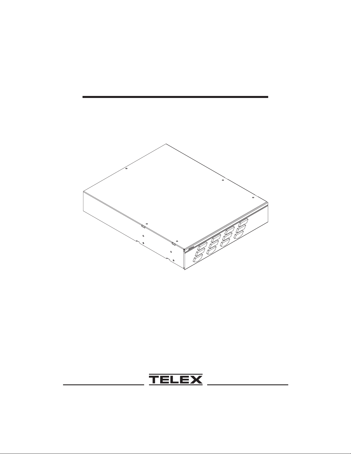
Model ES4000A
Intercom Expansion Station
®
Audiocom
Intercom Systems
®
Page 2

FCC Statement
This equipment uses and can radiate radio frequency energy that may cause interference to radio communications if not installed in accordance with this manual. The equipment has been tested and found to comply with the limits of a
Class A computing device pursuant to Subpart J, Part 15 of FCC Rules which
are designed to provide reasonable protection against such interference when operated in a commercial environment. Operation of this equipment in a residential
area may cause interference which the user (at his own expense) will be required
to correct.
This product meets Electromagnetic Compatibility Directive 89/336/EEC.
Introduction.
Thank you for purchasing the Audiocom ES4000A Intercom Expansion Station.
We hope the many design features of this product will satisfy your intercommunication requirements for many years to come. To get the most out of the
ES4000A, please take a few moments to look through this booklet before using
the Intercom Expansion Station for the first time.
2
Page 3

Table of Contents
Description .............4
Features ..............5
Installation .............7
Unpacking ............7
Configuration Pre-check..........7
Mounting Configurations .........10
Connection Notes ...........13
Cables.............22
Power-Up ............25
Sidetone Adjustments ..........25
Operation .............25
Specifications ............26
Factory Service and Parts Information .......29
3
Page 4
Audiocom®
Description
The ES4000A is an Expansion Station for the US2000A User Station. It interfaces 4
additional intercom channels to the US2000A, and it provides talk, listen and call but-
tons for the 4 additional channels. There are also 4 additional program inputs on the
back of the ES4000A, 1 for each added channel. Up to 4 ES4000A Expansion Stations
may be connected to the US2000A to add up to 16 channels (18 channels total). The
ES4000A typically utilizes the US2000A microphone and speaker (or microphone
headset) for communication with the added channels. The ES4000A also has individual
speaker outputs for independent monitoring of one or more of the 4 channels if desired.
The US2000A / ES4000A combination can be used as a simple, multi-channel inter-
com user station. In this configuration, the program inputs (and possibly the P Aoutput
of the US2000A) are most likely not used, and the station operator has only talk, listen
and call capability. It is also possible that advanced features of the US2000A, such as
Mic Kill Send, might be turned off. Alternatively,the US2000A / ES4000A can be
used as a master station. In this application, one or more program inputs and the PA
output may be connected, and the program signals to the intercom channels can be
turned on or off from the US2000A. Additionally, the Mic Kill Send feature can be en-
abled, and microphones on any channels may then be turned off from the US2000A.
+
12-15 VDC
®
Listen
Call
Talk
EXP
-
EXP
IN
OUT
54 9876
Listen
Call
Talk
3
321
3
4
4
SPEAKERS
LINE LEVEL
1 VRMS
5
6
Listen Listen
Call Call
Talk Talk
56
PROGRAM
INPUTS
BAL-OUT
UNBAL-IN
Telex
TELEX COMMUNICATIONS, INC.
Minneapolis, MN U.S.A.
PGM VOLUME
3456
ES4000A
®
CHANNEL 3-6 OUTPUTS
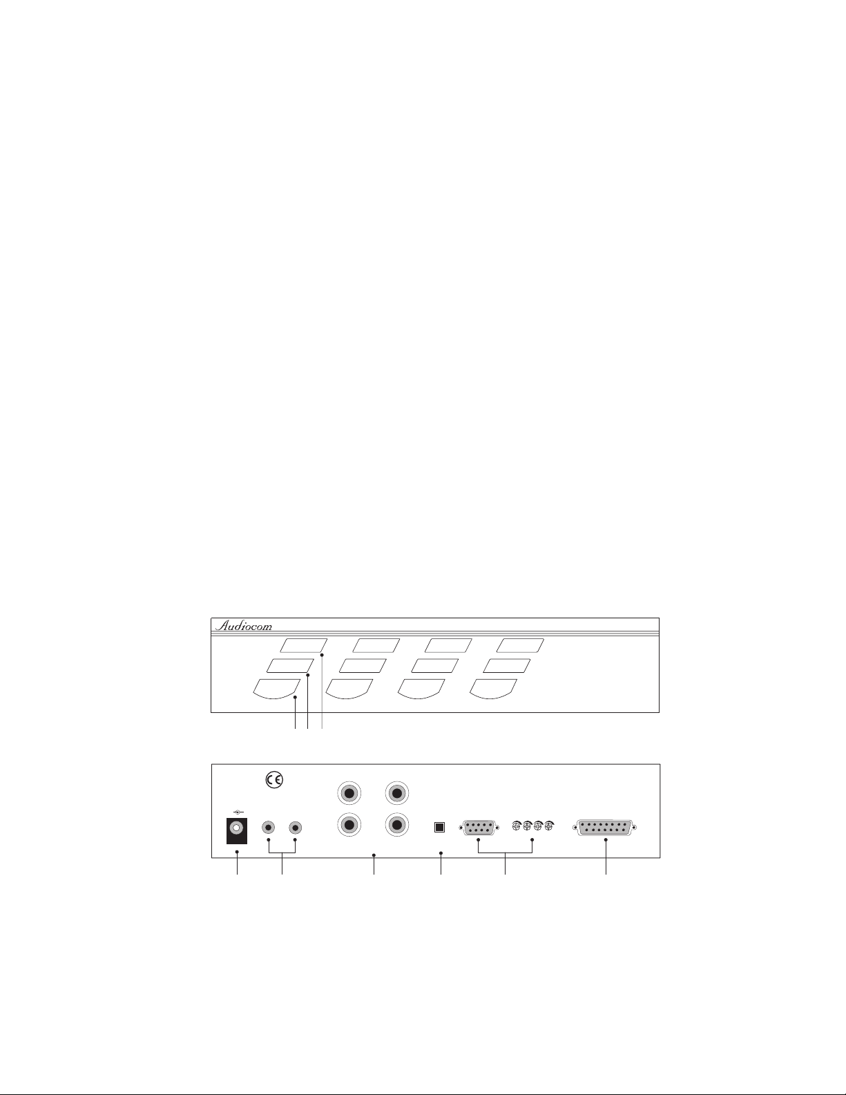
Figure 1. ES4000A Reference View (See numbered features on next page)
4
Page 5

Features
1. Intercom Talk Keys: Momentary or latching (hands-free) operation possible.
2. Call Keys: Used to call intercom channels and to indicate incoming calls.
3. Intercom Listen Keys: Momentary or latching operation possible.
4. Local Power Jack: The ES4000A can be powered from the intercom channels
via the CHANNEL 3-6 OUTPUTS connector (9). Alternatively, an optional
PS-L wall-pack accessory may be used to power the ES4000A from an AC out-
let. When power is sensed at the local power jack, the ES4000A automatically
disconnects from channel power. This means more channel power is available
for additional belt packs.
Important: The Local Power Jack only provides power to the ES4000A: it can-
☞
not be used to power the intercom system.
5. EXP IN and EXP OUT Connectors: The EXP IN connector receives the micro-
phone audio signal from the US2000A, and it sends the monaural mix of the
four ES4000A channels to the US2000A speaker or headset. The EXP OUT con-
nector connects to the EXP IN connector of an additional ES4000A. Up to 4
ES4000A Expansion Stations may be daisy chained with the EXP IN and EXP
OUT connectors. An EXP IN/OUT cable is supplied with each ES4000A.
6. SPEAKERS: Usually, the listen mix of all 4 ES4000A channels is sent to the
US2000A speaker or headset via the EXP IN connector. Alternatively, speakers
may be connected to one or more of the speaker outputs of the ES4000A.
7. BAL / UNBAL Switch: This selector switch sets the ES4000A for compatibility
with either Audiocom or Clear-Com* channel connector pin-outs, channel
power requirements, and call signaling requirements.
8. Program Inputs Connector and Trimmers: Each intercom channel has its own
program input and level adjust trimmer. For each program input, there is an inter-
* Brand names mentioned are the property of their respective companies.
5
Page 6
Audiocom®
nal jumper which routes the program either to the intercom channel only, or to
both the intercom channel and the US2000A headset or speaker (default setting).
Additionally, the program signal to the intercom channel may be turned on or
off via the US2000A front panel programming. There is also an internal program interrupt DIP switch which selects either automatic program interrupt
when the station operator activates a channel's talk key, or no program interrupt
during talk. The ES4000A program inputs connector may be broken out to common 3-pin XLR audio cables using an optional XP-4PGM Breakout Panel.
9. CHANNEL 3-6 OUTPUTS Connector: This connector provides the intercom channel audio input and output connections, as well as operating power when the
ES4000A is being powered from the intercom channels. Depending on the application, this connector can connect to either a PS4000 Power Supply, or to an
XP-ES4000 Breakout Panel. Examples of both connections are providedinthewiring diagrams which follow. A channel output cable is supplied with each ES4000A.
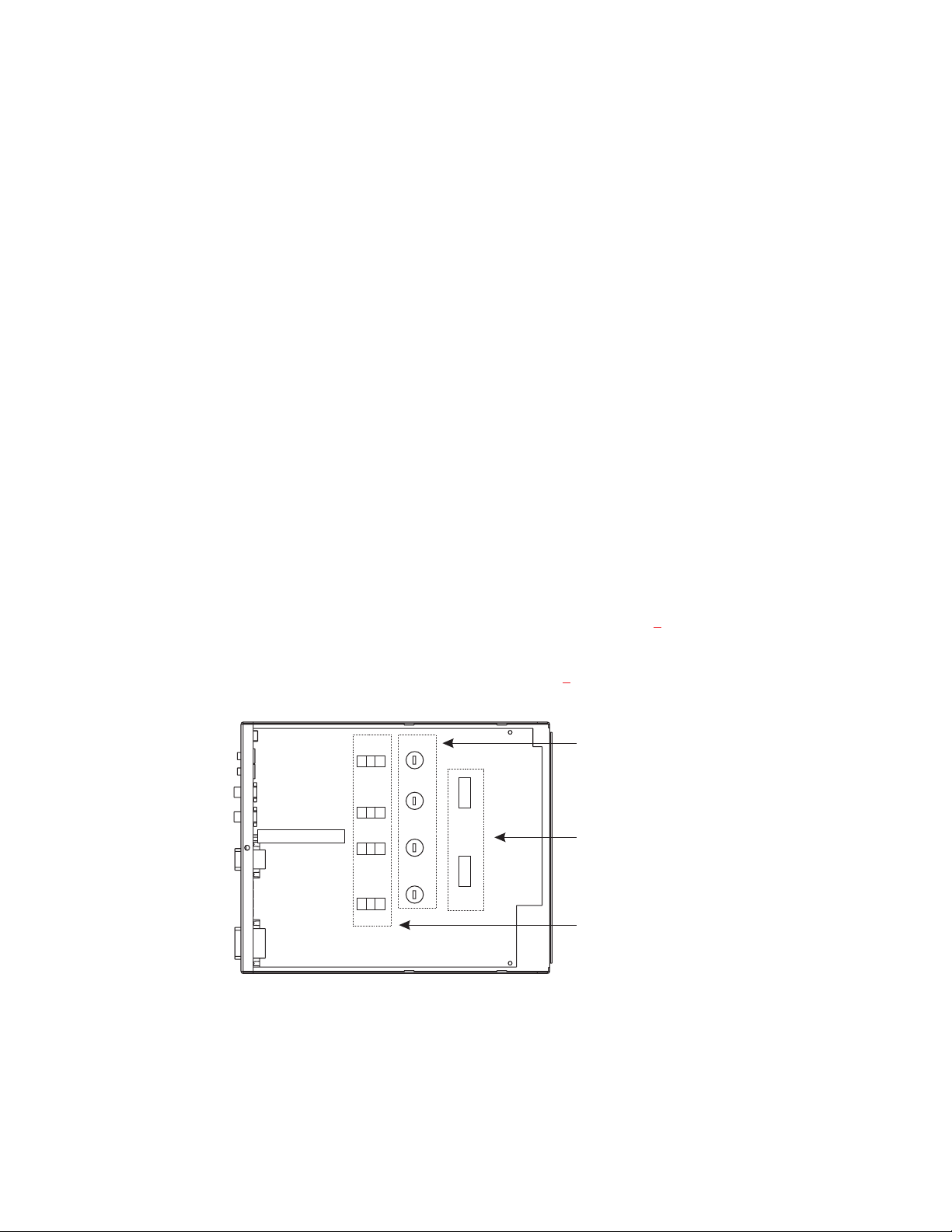
10. Configuration Switches, Jumpers and Sidetone Controls (Figure 2
). These let
you customize the operation of the ES4000A to match your intercom system requirements. See “Configuration Pre-check”, page 7, for details.
Ch 6
J21
3 2 1
Ch 5
SW2
BAL/UNBAL
J18
3 2 1
J16
3 2 1
J15
3 2 1
Ch 4
Ch 3
SW3
SW1
Figure 2. Locations of configuration switches, jumpers, and sidetone controls.
(Top cover removed.)
Sidetone Trimmers
DIP Switches
Program Listen Jumpers
6
Page 7

Installation
Unpacking
The ES4000A is supplied with the following items. Contact the shipper or your
Audiocom dealer immediately if anything is damaged or missing. Detach and fill out
the registration card and return it to Telex to properly register your intercom station.
Quantity Description
1 ES4000A Expansion Station
1 Warranty and registration card
1 User Instructions
2 Termination Plug
1 EXP IN/OUT Cable, with 1/8-inch (3.5 mm) phone plugs
1 CHANNEL OUTPUT Cable, with 15-pin connectors
4 Rubber feet (apply to bottom of ES4000A for desktop use)
Configuration Pre-check
Before making connections, read the configuration notes that follow, and make sure
that all switches and jumpers are properly set for your intended usage. Locations of
configuration switches and jumpers are shown in Figure 2
and jumpers require internal access. If access is required, remove one screw from the
top cover and 3 screws from each side.
. Only the DIP switches
DIP Switches
DIP switches and their default settings are listed in Table 1, page 8. The following
paragraphs provide additional details.
Program Interrupt DIP Switches
Each intercom channel has a dedicated program input. These can be used to feed
background music, mix-minus audio (for broadcasting usage) etc. to the intercom
channels. If external program sources will be connected to the ES4000A, you have a
choice of whether or not you want the program audio to interrupt (shut off) on the intercom channel while the US2000A/ES4000A station operator is talking.
7
Page 8
Audiocom®
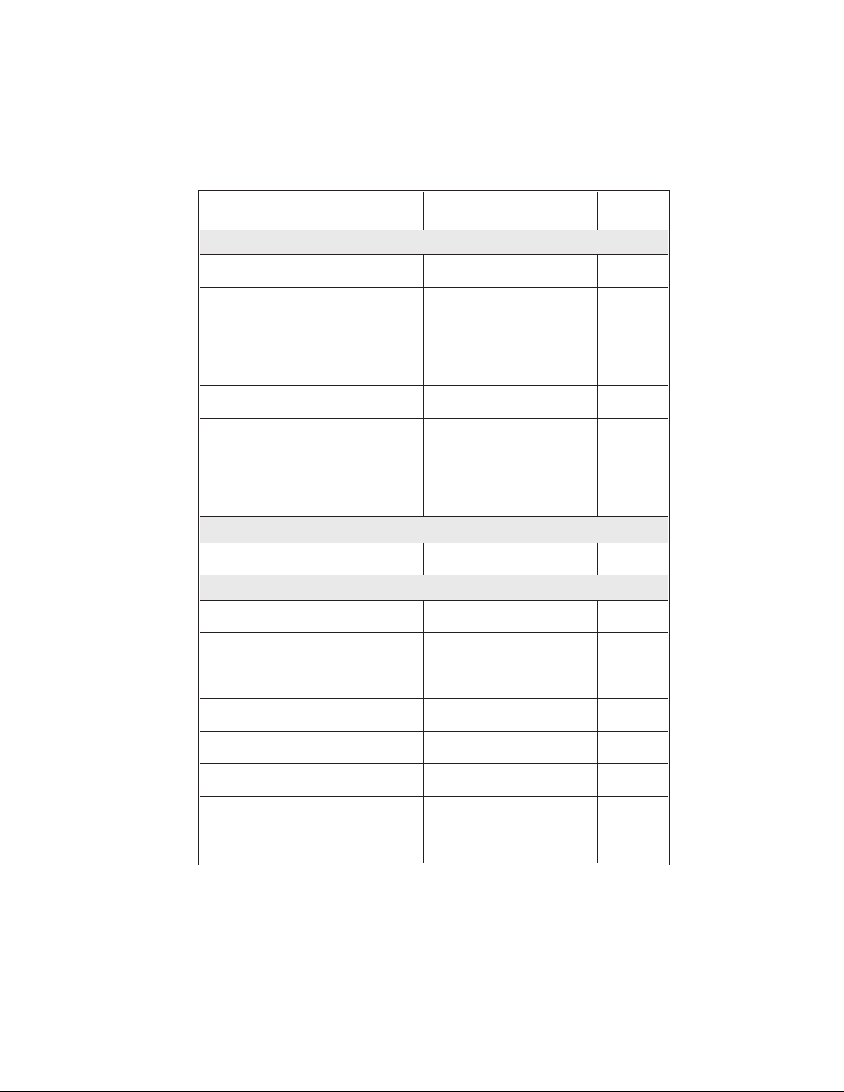
Table 1. Configuration Switch Settings
Switch
Number
SW1-1 Program Interrupt, Ch 6
SW1-2 Program Interrupt, Ch 5
SW1-3 Program Interrupt, Ch 4
SW1-4 Program Interrupt, Ch 3
SW1-5 Audiocom Call Send, Ch 3*
SW1-6 Audiocom Call Receive, Ch 3*
SW1-7 Audiocom Call Send, Ch 4*
SW1-8 Audiocom Call Receive, Ch 4*
Audiocom or Clear-Com
Description Settings Default
DIP Switch SW1 (Internal)
Push-button Switch SW2 (BAL-UNBAL Switch on Back Panel)
operation
DIP Switch SW3 (Internal)
On (Closed): Enabled
Off (Open): Disabled
On (Closed): Enabled
Off (Open): Disabled
On (Closed): Enabled
Off (Open): Disabled
On (Closed): Enabled
Off (Open): Disabled
On (Closed): Enabled
Off (Open): Disabled
On (Closed): Enabled
Off (Open): Disabled
On (Closed): Enabled
Off (Open): Disabled
On (Closed): Enabled
Off (Open): Disabled
Out: Audiocom (Balanced)
In: Clear-Com (Unbalanced)
Setting
Off
Off
Off
Off
On
On
On
On
Out
SW3-1 Audiocom Call Send, Ch 5*
SW3-2* Audiocom Call Receive, Ch 5*
SW3-3 Audiocom Call Send, Ch 6*
SW3-4 Audiocom Call Receive, Ch 6*
SW3-5* Not used
SW3-6* Not used
SW3-7* Not used
SW3-8* Not used
These switches apply only when the BAL/UNBAL switch on the back panel (SW2) is set to
*
the BAL position for Audiocom usage.When the switch is set to the UNBAL position, call
send and receive are always enabled.
On (Closed): Enabled
Off (Open): Disabled
On (Closed): Enabled
Off (Open): Disabled
On (Closed): Enabled
Off (Open): Disabled
On (Closed): Enabled
Off (Open): Disabled
On (Closed): N/A
Off (Open): N/A
On (Closed): N/A
Off (Open): N/A
On (Closed): N/A
Off (Open): N/A
On (Closed): N/A
Off (Open): N/A
8
On
On
On
On
Don’t care
Don’t care
Don’t care
Don’t care
Page 9
Audiocom Call Send and Receive DIP Switches
By default, all channels of the ES4000A can send and receive Audiocom call signals.
You can disable call send or call receive capability for selected channels if desired.
When the BAL / UNBAL switch on the back panel is set to the UNBAL position
☞
(for use with a Clear-Com Intercom System) the call send and call receive DIP
switches have no effect. Call send and call receive are always on for Clear-Com
usage.
Balanced/Unbalanced Switch (SW2)
This switch must be set to the balanced (BAL) position for use with an Audiocom
Intercom System. Set the switch to the unbalanced (UNBAL) position when using
the US2000A / ES4000A with a Clear-Com Intercom System.
Direct Program Listen Enable / Disable Jumpers
By default, each program input can be heard by intercom stations on the corresponding intercom channel. (This can be turned on or off for each program input via the
US2000A front panel programming. See "Turning the Program Inputs On and Off"
in the Operation section of the US2000A User Instructions.) Additionally, all program signals can be heard directly in the US2000A speaker or headset, and each program is output at the corresponding speaker jack on the back of the ES4000A. To
disable direct program listening for a program input, reset the appropriate jumper as
shown in Table 2. Locations of the jumpers are shown in Figure 2, page 6.
Table 2. Direct Program Listen Enable / Disable Jumpers
Jumper Description Settings for All Jumpers
J15 Program 3 direct to Headset or Speaker
J16 Program 4 direct to Headset or Speaker
J18 Program 5 direct to Headset or Speaker
J21 Program 6 direct to Headset or Speaker
Pins 2&3 Shorted: Enable
Pins 1&2 Shorted: Disable
9
Page 10
Audiocom®
Sidetone Trimmers
These trimmers are normally adjusted after all components are connected, and they
can be accessed through the bottom cover (Figure 15). Refer to the US2000A User
Manual for the sidetone adjustment procedure.
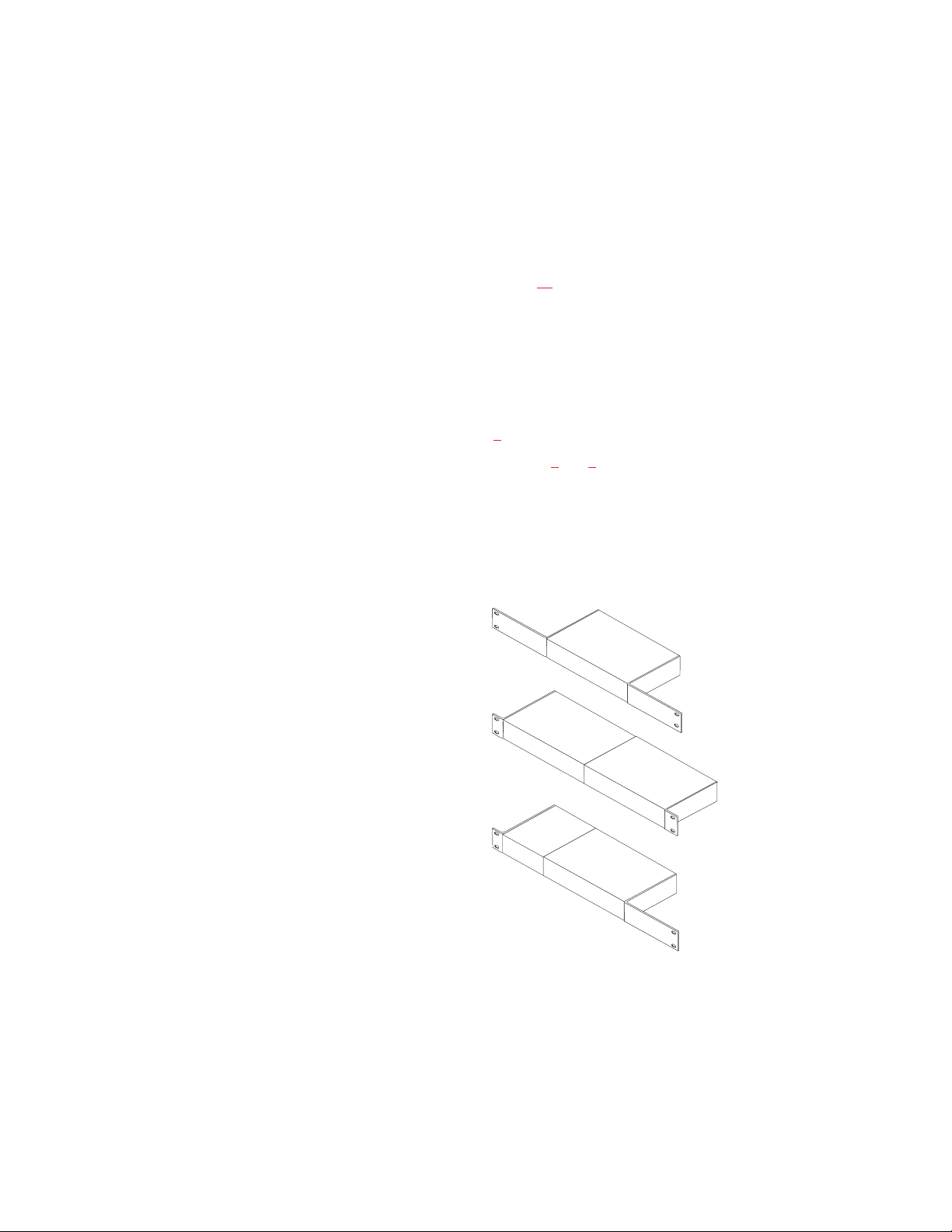
Mounting Configurations
The ES4000A can be used on a desktop, or it can be rack mounted. For desktop use,
install the 4 rubber feet supplied with the ES4000A. For rack mounting, use optional
Audiocom RMK Rack Mount Kits (Figure 3
). Many configurations are possible
when using the kits. Examples are shown in Figures 4 and 5.
When rack mounting components, you may not be able to access the sidetone
☞
trimmers after the components have been mounted. In this case, you can position
the components in the rack and make all required connections. Then, adjust the
sidetone trimmers before installing and tightening all rack mount screws.
RMK-S Single-Unit Rack Mount Kit
for one 1/2-rack wide Audiocom
component*
RMK-D Dual-Unit Rack Mount Kit
for two 1/2-rack wide Audiocom
components*
RMK-M Multi-Unit Rack Mount Kit
for mixed 1/2-rack and 1/4-rack
wide Audiocom components.Mounts
one 1/2-rack wide unit with 1/4-rack wide
components, or 3 1/4-rack wide components.
* 1/2-rack wide components:US2000A, ES4000A, PS2000L, SPS2000A,
PS4000, PS-X, SPK-2000. 1/4-rack wide components: SS-1000
Figure 3. Audiocom RMK Rack Mount Kits.
10
Page 11

BACK OF RACK
FRONT OF RACK
PS4000 (CH7 -10POWER)
®
PS-4000
1
3
Reset
2
4
11
XP-USPG
XP-4PGM XP-4PGM
BOP-1000 WITH 1 XP-USPG AND 1 XP-4PGM
SPARE
SPS2000A (CH1/2 POWER)
®
1
Combine
2
Isolate
®
Volume
Headset
Vox
Panel Mic
Volume
AllTalk
Mic Kill
PA
Listen Listen
Call Call
Talk Talk
12
US2000A (CH 1/2)
PS4000 (CH3 -6POWER)
SPS2000A
US2000A
Reset
®
®
Listen
Call
Call
Talk
Talk
3
®
Listen
Call
Call
Talk
Talk
3
Listen
4
Listen
4
Listen Listen
Call Call
Talk Talk
56
Listen Listen
Call Call
Talk Talk
56
PS-4000
1
3
Reset
2
4
ES4000A
ES4000A
2 ES4000A'S
(CH 3-6 AND CH 7-10)
Figure 4. Typical Rack Mount Configuration for a 10-Channel Master Speaker Station with Minimum Power Supply
Configuration. The SPS-2000A provides power for channels 1 and 2, and also provides the listening speaker for all 10 chan-
nels. A microphone must be connected to the US2000A for talk on the 10 channels. Each PS4000 provides power for 4 intercom channels and also interfaces an ES4000A to the intercom channels. The XP-USPG interfaces 2 external program inputs to
the US2000A, and also interfaces the US2000A to an external PA system. Each XP-4PGM interfaces 4 external program
sources to an ES4000A. Connections and further details for this configuration are shown in Figure 6
. Note: An additional rack
space is shown between the two PS4000 power supplies. This may be required to prevent power supply overheating when the
ambient air temperature is high.
Page 12

12
BACK OF RACK
FRONT OF RACK
PS2000L (CH5 POWER) PS2000L (CH6 POWER)
®
PS2000L (CH3 POWER) PS2000L (CH4 POWER)
®
PS2000L
1
Combine
Reset
2
Isolate
PS2000L
1
Combine
Reset
2
Isolate
®
Combine
2
Isolate
®
Combine
2
Isolate
Audiocom®
PS2000L
1
Reset
PS2000L
1
Reset
BOP-1000 WITH 1 XP-USPG, 1 XP-4PGM, AND 1 XP-ES4000
XP-USPG XP-4PGM
XP-ES4000
SPS2000A (CH1 POWER) PS2000L (CH2 POWER)
®
®
Volume
Headset
Mic Kill
Vox
PA
Panel Mic
AllTalk
Volume
1
Combine
2
Isolate
Listen Listen
Call Call
Talk Talk
12
SPS2000A
US2000A
Reset
®
Combine
2
®
Listen
Listen
Call
Call
Talk
Talk
3
4
Listen Listen
Call Call
Talk Talk
56
Isolate
PS2000L
1
Reset
ES4000A
US2000A ES4000A
Figure 5. Typical Rack Mount Configuration for a 6-Channel Master Speaker Station with Maximum Power Supply
Configuration. Each channel has a separate power supply, and the SPS-2000A on channel 1 also provides the listening
speaker for all 6 channels. A microphone must be connected to the US2000A for talk on the 6 channels. The XP-USPG
interfaces 2 external program inputs to the US2000A, and also interfaces the US2000A to an external PA system. The
XP-4PGM interfaces 4 external program sources to the ES4000A. The XP-ES4000 interfaces 4 of the PS2000L power supplies
to the 4 channels of the ES4000A. The connection between the US2000A and the ES4000A, as well as the connections of the
XP-USPG and XP-4PGM, are shown in Figure 6
power supply connections for the ES4000A are shown in Figure 9
. The power supply connections for the US2000A are shown in Figure 7. The
. Note: Additional rack spaces are shown between the rows
of power supplies. This may be required to prevent power supply overheating when the ambient air temperature is high.
Page 13

Connection Notes
Typical connections for the US2000A, ES4000A and various power supplies are
•
shown starting with Figure 6, page 14. Select the configuration which most
closely matches your intended usage.
The US2000A and ES4000A normally draw operating power from the intercom
•
channel power supplies (SPS2000A, PS2000L, etc.). Alternatively, you can use
optional PS-L Wall-pack Power Supplies. If you are using PS-L Wall-packs,
connect them to the 12-15 VDC jacks on the back panels of the US2000A and
ES4000A. When PS-L Wall-packs are used, the US2000A / ES4000A will not
draw power from the intercom channel power supplies, leaving more power for
belt packs.
Important: The PS-L power supply only provides power for the station that it is
☞
connected to. You cannot use a PS-L to power the intercom channels!
• Never connect more than 1 SPS2000A, PS2000L, or PS4000 Power Supply to
the same intercom channel. This will cause poor audio quality and increased
noise. Typically, all power supplies are located at a central location, such as a
central master station. This lets the central master station operator turn off the
intercom system when it is not being used.
•
Termination Plugs: The ES4000A is supplied with 2 termination plugs for special applications where 1 or more channels are unpowered. Figures 12, page 20
and 13, page 21 show examples of how to use these plugs. If all of your intercom channels will be powered from an SPS2000A, PS2000L, or PS4000 power
supply, the termination plugs are not needed.
13
Page 14

Audiocom®
PGM
PGM
2 IN
9 109
CH 1-2
XP-USPG
PGM
6 IN
9 99
CH 3 - 6
XP-4PGM
PGM
10 IN
1 IN
PGM
5 IN
PGM
9 IN
PGM
4 IN
PGM
8 IN
PA
OUT
FRONT
BACK
PGM
3 IN
9
FRONT
BACK
7
PGM
7 IN
CH 1-2
SPS2000A
100-240VAC 60/50 HZ
US2000A
PROGRAM
INPUTS
+
-
P.A.
12-15VDC
7
8
5
CH 3-6
PS4000
ES4000A
EXP
+
-
IN
12-15VDC
SPEAKER
INPUT 1
®
INPUT 2
CHN 1
CHN 2
VOL
PGM 2
CLASS 2WIRING 2A 24VDC
1
CHN 2
1
CAT.NO.9000-7336-00 MADE IN USA
CHN 3 CHN 4
MADE IN USA
TO BELT PACKS
AND REMOTE
MASTER STATIONS
CH 1
CH 2
CH 3
CH 4
CH 5
CH 6
CH 7
CH 8
CH 9
CH 10
111111
LINE LEVEL
1VRMS
4
SPEAKERS
LINE LEVEL
1VRMS
EXP
OUT
1
BAL - OUT
UNBAL - IN
PUSH PUSH
VOL
PGM 1
CHN 1
1
2
1
1 1
CHN 1 CHN 2
CONNECTTO ES-4000
6
SPEAKERS
3
5
EXP
4
6
OUT
BAL-OUT
UNBAL-IN
LINE LEVEL
1VRMS
®
Telex
PROGRAM
INPUTS
PGMVOLUME
CAN 3-6 OUTPUTS
3456
9 999
CH 7 - 10
XP-4PGM
FRONT
BACK
5
CH 7-10
PS4000
ES4000A
EXP
+
-
EXP
IN
OUT
12-15VDC
CAT.NO.9000-7336-00 MADE IN USA
CHN 3 CHN 4
CHN 1 CHN 2
CONNECTTO ES-4000
CLASS 2WIRING 2A 24VDC
6
SPEAKERS
3
5
4
6
BAL-OUT
LINE LEVEL
UNBAL-IN
1VRMS
®
Telex
PROGRAM
INPUTS
PGMVOLUME
CAN 3-6 OUTPUTS
3456
Note: For further information about the cable numbers, see page 22.
7
5
TO ANOTHER ES4000A
Figure 6. Central master station with simple power supply configuration. This
10-channel station provides all of the channel power and program input connections
for the intercom system. This configuration should only be used at one point in the
intercom system. It is ideal for smaller intercom systems with fewer remote intercom
stations. For optional power configurations that permit more stations, see Figures 7
through 10. Note: The SPS2000A power supply includes a speaker and is typically
used for intercom listening, with a gooseneck microphone connected to the
US2000A for talk-back. Alternatively, a headset with a microphone may be used. In
this case, no speaker is needed, and a PS2000L power supply may therefore be
used in place of the SPS2000A.
14
Page 15

SPS2000A
Channel 1 Power and
All-Channel Speaker
Combine / Isolate Switch
set to Combine
SPEAKER
INPUT 1
®
100-240VAC 60/50 HZ
INPUT 2
CHN 1
LINE LEVEL
1VRMS
PS2000L
Channel 2 Power
Combine / Isolate Switch
set to Combine
CHN 2
MADE IN USA
100-249VAC 60/50 HZ
®
CHN1
CHN2
MADEIN USA
1
PROGRAM
+
12-15VDC
4
INPUTS
-
1
SPEAKERS
LINE LEVEL
1VRMS
2
EXP
P.A.
OUT
BAL - OUT
UNBAL - IN
PUSH PUSH
VOL
VOL
PGM 2
PGM 1
CHN 1
CHN 2
1
Note:
US2000A Internal
Note: For further information about the cable numbers, see page 22.
1
To ½ of stations
on channel 1
1 1 1
To ½ of stations
on channel 1
To ½ of stations
on channel 2
Figure 7. Maximum Power Configuration for Channels 1 and 2. This power supply configuration should only be used at one point in channels 1 and 2. Typically, it
is set up at the central master station. This configuration permits about twice as
many remote stations on channels 1 and 2 than the configuration shown in Figure
. Note: A PS2000L may be substituted for the SPS2000A for headset-only opera-
6
tion.
DIP switches set
for monaural
operation (default)
To ½ of stations
on channel 2
15
Page 16

Audiocom®
Note: For further information about the cable numbers, see page 22.
BACK
XP-ES4000
TO US2000A
EXP IN CONNECTOR
5
EXP
+
-
IN
12-15VDC
EXP
OUT
CH 3-6
ES4000A
SPEAKERS
5
3
6
4
LINELEVEL
1VRMS
PROGRAM
INPUTS
BAL-OUT
UNBAL-IN
5
TOTHE EXP IN CONNECTOR
OF ANOTHER ES4000A
6
PGMVOLUME
3456
Telex
®
CAN3-6 OUTPUTS
FRONT
PUSH PUSH PUSH
1
100-249VAC 60/50 HZ
®
1
1
1
1
PUSH
TO REMOTE MASTER
STATIONS AND BELT PACKS
1
1
1
CHN1
CLASS2 WIRING 1.5A 24VDC
CHN2
MADEIN USA
100-249VAC 60/50 HZ
PS2000L Power Supplies
Combine / Isolate switches set to Isolate
CH 6
CH 5
CH 4
CH 3
CH 3CH 6 CH 5 CH 4
®
CHN1
CHN2
CLASS2 WIRING 1.5A 24VDC
MADEIN USA
Figure 8. Intermediate Power Configuration for Channels 3-6 (or 7-10, 11-14,
etc.). This power supply configuration should only be used at one point in each
group of 4 channels. Typically, it is set up at the central master station. It permits
about twice as many remote stations on the 4 channels than is possible with the
power supply configuration shown in Figure 6
.
16
Page 17

TO US2000A
EXP IN CONNECTOR
Note: For further information about the cable numbers, see page 22.
XP-ES4000
5
EXP
+
-
IN
12-15VDC
EXP
OUT
CH 3-6
ES4000A
SPEAKERS
5
3
6
4
LINELEVEL
1VRMS
®
Telex
PROGRAM
INPUTS
PGMVOLUME
CAN3-6 OUTPUTS
3456
BAL-OUT
UNBAL-IN
5
BACK
TOTHE EXP IN CONNECTOR
OF ANOTHER ES4000A
6
FRONT
PUSH PUSH PUSH
1
1
1
1
PUSH
TO 1/2 OF REMOTE
MASTER STATIONS
OR BELT PACKS
CH 6
CH 5
CH 4
CH 3
1
1
1
1
TO 1/2 OF REMOTE
CH 6
100-249VAC60/50 HZ
®
CH 5
100-249VAC60/50 HZ
CH 4
PS2000L Power Supplies
Combine / Isolate Switches
set to Combine
CHN1
CLASS2 WIRING 1.5A 24VDC
100-249VAC60/50 HZ
®
CH 3
CHN2
MADEIN USA
CHN1
CHN2
®
100-249VAC60/50 HZ
MADEIN USA
CHN1
CLASS2 WIRING 1.5A 24VDC
CHN2
MADEIN USA
®
CHN1
CLASS2 WIRING 1.5A 24VDC
CLASS2 WIRING 1.5A 24VDC
MASTER STATIONS
OR BELT PACKS
1
1
1
CHN2
MADEIN USA
CH 6
CH 5
CH 4
1
CH 3
Figure 9. Maximum Power Configuration for Channels 3-6 (or 7-10, 11-14, etc.).
This power supply configuration should only be used at one point in each group of
4 channels. Typically, it is set up at the central master station. It permits about four
times as many remote stations on the 4 channels than is possible with the power
supply configuration shown in Figure 6
.
17
Page 18

Audiocom®
Note: For further information about the cable numbers, see page 22.
BACK
XP-ES4000
TO US2000A
EXP IN CONNECTOR
5
EXP
+
-
IN
12-15VDC
EXP
OUT
CH 3-6
ES4000A
SPEAKERS
5
3
6
4
LINELEVEL
1VRMS
PROGRAM
INPUTS
BAL-OUT
UNBAL-IN
5
TOTHE EXP IN CONNECTOR
OF ANOTHER ES4000A
6
PGMVOLUME
3456
Telex
®
CAN3-6 OUTPUTS
FRONT
PUSH PUSH PUSH
1
1
CH 5
and
CH 6
100-249VAC60/50 HZ
®
CHN1
CHN2
CLASS2 WIRING 1.5A 24VDC
PS2000L Power Supply
Combine / Isolate switch set to Isolate
CH 4
100-249VAC60/50 HZ
PS2000L Power Supplies
CH 3
Combine / Isolate switches
set to Combine
MADEIN USA
1
1
1
1
PUSH
CH 6
CH 5
CH 4
CH 3
TO 1/2 OF REMOTE
MASTER STATIONS
AND BELT PACKS ON
CH 3 AND CH 4.
1
1
TO ALL REMOTE
MASTER STATIONS
AND BELT PACKS ON
CH 5 AND CH 6.
TO 1/2 OF REMOTE
MASTER STATIONS
AND BELT PACKS
ON CH 3 AND CH 4
®
100-249VAC60/50 HZ
CHN1
CLASS2 WIRING 1.5A 24VDC
1
CHN2
MADEIN USA
®
CHN1
CHN2
CLASS2 WIRING 1.5A 24VDC
MADEIN USA
CH 4
1
CH 3
Figure 10. Mixed Intermediate and Maximum Power Configuration for
Channels 3-6 (or 7-10, 11-14, etc.). This power supply configuration should only be
used at one point in each group of 4 channels. Typically, it is set up at the central
master station. In this example, channels 3 and 4 have about twice the capacity of
channels 5 and 6, while channels 5 and 6 have about twice the capacity as the configuration shown in Figure 6
.
18
Page 19

TO ADDITIONAL REMOTE
MASTER STATIONS
1
SPEAKERS
LINELEVEL
1VRMS
2
EXP
OUT
+
-
12-15VDC
OR BELT PACKS
VOL
PGM1
BAL-OUT
CHN1
UNBAL-IN
CH 3-6
ES4000A
SPEAKERS
3
5
EXP
EXP
4
6
IN
OUT
LINELEVEL
1VRMS
1
1
PUSH PUSH
VOL
PGM2
CHN2
PROGRAM
INPUTS
PGMVOLUME
3456
BAL-OUT
UNBAL-IN
Telex
CH 1
CH 2
®
CAN3-6 OUTPUTS
CH 1
CH 2
PS-L
-
+
12-15VDC
FROM MASTER STATION
OR BELT PACK
SPK2000
INPUT1
INPUT2
BAL
BACK
4
®
1
1
XP-ES4000
CH 1-2
US2000A
PROGRAM
INPUTS
+
-
P.A.
12-15VDC
5
6
CH 6
CH 5
CH 4
CH 3
FRONT
PUSH PUSH PUSH
1
1
1
1
FROM MASTER STATION
OR BELT PACK
BACK
XP-ES4000
1
1
1
PUSH
1
TO ADDITIONAL REMOTE
MASTER STATIONS
OR BELT PACKS
5
CH 7-10
ES4000A
SPEAKERS
3
5
EXP
+
-
EXP
IN
OUT
12-15VDC
PROGRAM
4
6
BAL-OUT
LINELEVEL
UNBAL-IN
1VRMS
CH 6
CH 5
CH 4
CH 3
®
Telex
INPUTS
PGMVOLUME
CAN3-6 OUTPUTS
3456
6
CH 10
CH 9
CH 8
CH 7
FRONT
PUSH PUSH PUSH
1
1
1
1
FROM MASTER STATION
OR BELT PACK
1
1
1
PUSH
1
TO ADDITIONAL REMOTE
MASTER STATIONS
OR BELT PACKS
Note: For further information about the
cable numbers, see page 22.
CH 10
CH 9
CH 8
CH 7
Figure 11. Typical remote 10-channel master station or user station. This intercom station can have the same functionality as the central master station shown in
Figure 6. Alternatively, you can disable some of the advanced features, such as Mic
Kill, program inputs, etc. This will limit the station’s functionality to be a common
user station with multi-channel talk/listen capability.
19
Page 20

Audiocom®
TO US2000A
EXP IN CONNECTOR
Note: For further information about the cable numbers, see page 22.
XP-ES4000
BACK
FRONT
PUSH PUSH PUSH
1
1
TERMINATION
PLUGS
PUSH
5
EXP
+
-
IN
12-15VDC
EXP
OUT
CH 3-6
ES4000A
SPEAKERS
3
5
4
6
LINELEVEL
1VRMS
®
Telex
PROGRAM
INPUTS
PGMVOLUME
CAN3-6 OUTPUTS
3456
BAL-OUT
UNBAL-IN
5
TOTHE EXP IN CONNECTOR
OF ANOTHER ES4000A
6
1
1
WET LINES TO 1/2 OF REMOTE
MASTER STATIONS OR BELT PACKS ON
CHANNELS 5 AND 6
1
1
DRY LINESTO REMOTE STATIONS
ON CHANNELS 3 AND 4
CH 6
CH 5
CH 3
CH 4
CH 6
100-249VAC60/50 HZ
CH 5
PS2000L Power Supplies
Combine / Isolate Switches
®
100-249VAC60/50 HZ
CHN1
CLASS2 WIRING 1.5A 24VDC
CHN2
MADEIN USA
®
CHN1
CHN2
CLASS2 WIRING 1.5A 24VDC
MADEIN USA
1
1
CH 6
CH 5
WET LINES TO 1/2 OF REMOTE
MASTER STATIONS OR BELT PACKS ON
CHANNELS 5 AND 6
set to Combine
Figure 12. Using the termination plugs supplied with the ES4000A for mixed
wet- and dry-line operation. In this example, channels 5 and 6 are powered from
a PS2000L Power Supply (wet lines), while channels 3 and 4 are operated without
power (dry lines). Any remote station connected to channel 3 or 4 must supply its
own power. For example, a US2000A that is powered by a PS-L Power Supply
could be connected to channels 3 and 4. The advantage of dry-line operation is
that intercom stations may be operated over a much greater distance.
20
Page 21

SPK2000
4
-
+
12-15VDC
INPUT1
INPUT2
BAL
PS-L PS-L
®
PS-L
CH 1-2 US2000A
PROGRAM
INPUTS
1
SPEAKERS
LINELEVEL
+
-
1VRMS
2
EXP
P.A.
OUT
12-15VDC
5
CH 3-6 ES4000A
3
EXP
+
-
EXP
4
IN
OUT
12-15VDC
TERMINATION
CH 1
CH 2
PLUGS
1
1
+
12-15VDC
PUSH
VOL
PGM1
BAL-OUT
CHN1
UNBAL-IN
SPEAKERS
5
PROGRAM
INPUTS
6
BAL-OUT
LINELEVEL
UNBAL-IN
1VRMS
PGM2
PGMVOLUME
3456
PUSH
VOL
CHN2
®
Telex
CAN3-6OUTPUTS
SPK2000
4
-
INPUT1
INPUT2
BAL
®
PS-L
CH 1-2 US2000A
PROGRAM
INPUTS
1
SPEAKERS
LINELEVEL
+
-
1VRMS
2
EXP
P.A.
OUT
12-15VDC
5
CH 3-6 ES4000A
3
EXP
+
-
EXP
4
IN
OUT
12-15VDC
1
1
PUSH
VOL
PGM1
BAL-OUT
CHN1
UNBAL-IN
SPEAKERS
5
PROGRAM
INPUTS
6
BAL-OUT
LINELEVEL
UNBAL-IN
1VRMS
VOL
PGM2
PGMVOLUME
3456
Telex
PUSH
CHN2
®
CAN3-6OUTPUTS
CH 1
CH 2
21
BACK
XP-ES4000
PS-L
6
BACK
XP-ES4000
PS-L
6
1
1
FRONT
PUSH
PUSH
PUSH
PUSH
1
1
1
1
CH 3
CH 4
CH 5
CH 6
TERMINATION PLUGS
FRONT
PUSH
PUSH
PUSH
PUSH
1
1
TO ADDITIONAL
LOCALLY POWERED
INTERCOM STATIONS
Note: Forfurther information about the cable numbers, see page 22
.
Figure 13. Using termination plugs for all dry-line connection. In this example, all components use local power supplies,
and no power is supplied on the intercom channels. All stations may be operated over a much greater distance than is possible when using powered channels. Important: there should only be one termination plug used in each channel.
CH 6
CH 5
CH 4
CH 3
Page 22

Audiocom®
Cables
The numbers below correspond to the cable numbers in the connection drawings on
the previous pages.
1. 1-channel intercom cable. Sold separately. Use Telex "ME" cables, below. Or,
build per Figure 14.
ME-25: 25' (7.6 m) cable with Male and Female 3-pin XLR connectors.
ME-50: 50' (15.2 m) cable with Male and Female 3-pin XLR connectors.
ME-100: 100' (30.4 m) cable with Male and Female 3-pin XLR connectors.
2. 2-channel intercom cable. Sold separately. Use Telex "ME /2" cables, below. Or,
build per Figure 14
ME-25/2: 25' (7.6 m) cable with Male and Female 6-pin XLR connectors.
ME-50/2: 50' (15.2 m) cable with Male and Female 6-pin XLR connectors.
ME-100/2: 100' (30.4 m) cable with Male and Female 6-pin XLR connectors.
3. Y adapter cable. Sold separately. Use Telex CA-23-16. Or, build per Figure 14.
4. 3 ft (0.91 m) speaker cable with RCA plugs. One supplied with each SPS2000A,
SPK-1000, and SPK-2000.
5. 18" (457 mm) EXP IN/OUT cable, stereo miniplug to stereo miniplug. One supplied with each ES4000A.
6. 18" (457 mm) CHANNEL OUTPUT cable, 15-pin Male Dsub to 15-pin Female
Dsub. One supplied with each ES4000A.
7. Shielded patch cable, 9-pin Male Dsub to 9-pin Female Dsub. Customer local
purchase: available at Radio Shack, etc. Note: All pins must be connected
straight through: do not use an RS232 computer cable!
8. Shielded patch cable, stereo miniplug to stereo miniplug. Customer local pur-
.
chase. Available at Radio Shack, etc.
22
Page 23

9. Shielded audio cable. Must have male 3-pin XLR connector at one end for connection to the XP-USPG or XP-4PGM program inputs. Pin-out for program inputs is as follows:
Pin 1: common
Pin 2: + program input
Pin 3: - program input
10. Shielded audio cable. Must have male 3-pin XLR connector at one end for connection to the XP-USPG PA output. Pin-out for PA output is as follows:
Pin 1: common
Pin 2: + PA output
Pin 3: - PA output
23
Page 24

Audiocom®
TYPICAL 1-CHANNEL CABLEWIRING
33
22
1
Shield Shield
CableType:22AWG Stranded, 2-PairTwisted-wire, with Shield
Connector Type: 3-Pin XLR Audio (Neutrik or Switchcraft)
Pin 1: Common
Channel Audio / Power
Pin 2:
Pin 3: Channel Audio / Power
: Earth ground
Shield
44
33
66
55
1
Shield Shield
CableType:22AWG Stranded, 3-PairTwisted-wire, with Shield
Connector Type: 6-Pin XLR Audio (Neutrik only, not compatible with 6-pin Switchcraft)
Pin 1: Channel 1 & 2 Common
Pin 2: No connection
Pin 3: Channel 1 Audio / Power
Pin 4: Channel 1 Audio / Power
Pin 5: Channel 2 Audio / Power
Pin 6: Channel 2 Audio / Power
Shield
: Earth ground
3
2
Ch1
1
Case
3
2
Ch2
1
Shield
Pair 1
Pair 2
1 (Both wires)
*
Denotes twisted pair.
Denotes shield.
TYPICAL 2-CHANNEL CABLEWIRING
Pair 1
Pair 2
Pair 3
Denotes twisted pair.
Denotes shield.
“Y”CABLE WIRING
Pair 1
Pair 2
Pair 3
1 (Both wires)
4
3
6
5
1 (Both wires)
Shield
*
Use second drain wire if available, or add an extra section of wire.
*
Standard cables are generally constructed using a male connector at one end and a
female connector at the other end.This allows several cables to be interconnected to
create longer cable runs.
also typically provide both a male and female Neutrik connector for each intercom
channel.This permits loop-through connection of several intercom stations using the
standard cables.
each channel. Audiocom wallplates use male Neutrik connectors.
Audiocom power supplies use a 3-pin male Neutrik connector for
Audiocom master stations, speaker stations and belt packs
Figure 14. Audiocom intercom cable wiring diagrams
24
Page 25

Ch 3
Sidetone
Ch 4
Sidetone
Ch 5
Sidetone
Ch 6
Sidetone
Figure 15. Sidetone Trimmer Access on Bottom of ES4000A
Power-Up
The ES4000A channels power-up identically to channels 1 and 2 of the US2000A.
Refer to the US2000A User Instructions for all power-up information.
Sidetone Adjustments
Use the sidetone adjustment procedure as described in the US2000A User Instructions, except substitute channel 3, channel 4, etc. The locations of the ES4000A sidetone trimmers are shown in Figure 15
.
Operation
The ES4000A channels operate identically to channels 1 and 2 of the US2000A. Refer to the US2000A User Instructions for all operating information.
25
Page 26

Audiocom®
Specifications
General
Power Requirements:
Voltage:
Phantom Power:24 VDC nominal (12 to 30 VDC)
Local Power (with PS-L Wall-pack Power Supply or equivalent):14 to 15 VDC
Current: 65 mA, quiescent;150 mA maximum
Dimensions: 1.75" (44.5 mm) high, 8.25" (209.6 mm) wide, 10.0" (250 mm) deep
Environmental Requirements:
Storage: -20°C to 80°C;0% to 95% humidity, non-condensing
Operating: -15°C to 60°C;0% to 95% humidity, non-condensing
Intercom Channels, Balanced Mode (BAL / UNBAL switch set to BAL position)
Output Level:1 Vrms nominal
Input Impedance: 300 ohms
Bridging Impedance: greater than 10,000 ohms
Sidetone: -40 dB, 35 dB adjustable range
Call Signaling:
Send: 20 kHz ±100 Hz, 0.47 Vrms ± 2dB
Receive:20 kHz ±800 Hz, 100 mVrms
Mic-Kill Frequency:
Send: 24 kHz ±100 Hz, 0.5 Vrms ± 2dB
Receive:24 kHz ±800 Hz, 100 mVrms
Noise Contribution: less than -70 dB
Common Mode Rejection Ratio: greater than 50 dB
Intercom Channel, Unbalanced Mode (BAL / UNBAL switch set to UNBAL position)
Output Level:1 Vrms ±10%
Input Impedance: 150 ohms
Bridging Impedance: 10,000 ohms ±5%
Sidetone: -40 dB, 35 dB ±10% adjustable range
Call Signaling:
Send: 11 ±2 VDC
Receive:4 VDC
Speaker Output
Level:1.0 Vrms, ±2 dB (0 dB nominal)
Impedance: 1000 ohms nominal
Program Input
Voltage Gain Adjustment Range (program Input to channel output, with 100 mVrms input): 25
±3 dB (2.6 Vrms maximum, unit is factory-set to 1.0 Vrms)
Input Impedance: Balanced, 75 Kohm ±10%; unbalanced, 38 Kohm ±10%
26
Page 27

Frequency Response
EXP IN to/from Channel, EXP IN to/from EXP OUT, Channel to Speaker: 200 Hz to 8 kHz
+1/-3 dB
Total Harmonic Distortion: Less than 0.5 %
Connector Pin-outs
12-15 VDC Jack
Connector Type: 2.0 mm DC jack
Internal pin: + 12 to 15 VDC
External Ring: Common
EXP IN Jack
Connector Type: 1/8" (2.0 m) stereo phone jack
Tip: Listen input
Ring: Talk output
Sleeve:Common
EXP OUT Jack
Connector Type: 1/8" (2.0 m) stereo phone jack
Tip: Talk output
Ring: Listen input
Sleeve:Common
SPEAKER Jacks
Connector Type: RCA Phono jack
Tip: Speaker output high
Sleeve:Common
PROGRAM INPUTS Connector
Connector Type: DB9F Female, 9-pin D-subminature
Pin 1: Common
Pin 2: Channel 3 program in low
Pin 3: Channel 4 program in low
Pin 4: Channel 5 program in low
Pin 5: Channel 6 program in low
Pin 6: Channel 3 program in high
Pin 7: Channel 4 program in high
Pin 8: Channel 5 program in high
Pin 9: Channel 6 program in high
27
Page 28

Audiocom®
CHANNEL 3-6 OUTPUTS Connector
Connector Type: DB15F Female, 15-pin D-subminature
Pin 1: Channel 3 intercom audio input/output high
Pin 2: Channel 3 intercom audio input/output low
Pin 3: Common
Pin 4: Channel 5 intercom audio input/output high
Pin 5: Channel 5 intercom audio input/output low
Pin 6: Common
Pin 7: Common
Pin 8: Common
Pin 9: Common
Pin 10: Channel 4 intercom audio input/output high
Pin 11: Channel 4 intercom audio input/output low
Pin 12: Common
Pin 13: Channel 6 intercom audio input/output high
Pin 14: Channel 6 intercom audio input/output low
Pin 15: Power (30 VDC)
28
Page 29

Factory Service and Parts Information
When returning equipment for repair include your return address, telephone number
and proof of date of purchase, along with a description of the problem.*
The address for Audiocom equipment returns and parts information is:
Service Department
Telex Communications, Inc.
West 1st Street
Blue Earth, Minnesota 56013 U.S.A.
Telephone: (507) 526-3205
(Collect calls not accepted)
Warranty Repairs - If in warranty, no charge will be made for the repairs. Equipment
returned for warranty repair must be sent prepaid and will be returned prepaid.
Non-Warranty Repairs - Equipment that is not under warranty must be sent prepaid
to Telex. If requested, an estimate of repair costs will be issued prior to service. After
your approval and completion of the repairs, the equipment will be returned on a collect basis. Collect charges may be avoided by sending a signed check for payment in
full along with your signed estimate approval form (shipping charges are included in
the estimate).
* For sales / technical support and system design contact:
Pro Audio Sales Department
Telex Communications, Inc.
12000 Portland Avenue South
Burnsville, Minnesota 55337 U.S.A.
Telephone: (952) 884-4051
(Collect calls not accepted)
29
Page 30

Audiocom®
Notes
30
Page 31

Notes
31
Page 32

Addendum
Document Affected: ES4000A User Instructions, Publication Number
9350-7551-000 Rev. A
Addendum Number: 1
General Instructions: Use this addendum with Revision A of the user instruc-
tions. This information will be included in Revision B.
Page 6, item 6: The description should be 18" (457 mm) CHANNEL OUTPUT
cable, 15-pin Male Dsub to 15-pin Male Dsub. One supplied with each
ES4000A.
Pages 16-21: All cables labeled with number 6 should be labeled with number
11. The description for cable number 11 is 18" (457 mm) CHANNEL OUTPUT
cable, 15-pin Male Dsub to 15-pin Female Dsub. One supplied with each
XP-ES4000.
Notes:
•
When you are connecting an ES4000A to a PS4000 Power Supply, use the
CHANNEL OUTPUT cable that is supplied with the ES4000A (cable 6).
•
When you are connecting the ES4000A to an XP-ES4000, use the
CHANNEL OUTPUT cable that is supplied with the XP-ES4000 (cable
11). The CHANNEL OUTPUT cable that is supplied with the ES4000A is
not used.
®
Page 33

®
TELEXCOMMUNICATIONS,INC.12000 Portland Ave.So.,Burnsville,MN55337 U.S.A.
9350-7551-000Rev.B,8/00
 Loading...