

Page 1
Telex
Operating Instructions
ENG-1
Portable Receiver
R
Page 2

Table of Contents
Page
GENERAL INFORMATION ...................................................................... 1
FREQUENCY SELECTION....................................................................... 2
ENG-1 PORTABLE RECEIVER ................................................................ 2
Receiver Specifications: ENG-1 ...............................................................3
Features......................................................................................................4
Power and Battery Requirments.............................................................4
DC Power “dc input” Jack..................................................................... 4
Line Output Jack.....................................................................................4
Power ON\OFF.......................................................................................5
Line Output Control .............................................................................. 5
Squelch Control................................................................... ...................6
Headphone “PHONES” Level Control ..................................................6
Headphone “PHONES” Jack................................................................. 6
Low Battery Indicator............................................................................ 6
TX ON Indicator....................................................... ..............................6
TX Overload Indicator........................................................................... 7
Antenna...................................................................................................7
Belt Clip..................................................................................................7
ENG-1 Set-up.............................................................................................7
Power\Low Battery Indication ...............................................................7
Antenna...................................................................................................8
Audio Output..........................................................................................9
Interference.............................................................................................9
FCC INFORMATION ................................................................................18
WARRANTY SERVICE INFORMATION................................................19
-i-
Page 3

GENERAL INFORMATION
Individual accessories are available to add to your wireless system.
3.5mm Mono Plug to 3.5mm Mono plug ...........71094-000
3.5mm Mono Plug to 1/4" mono phone plug .....71095-000
3.5mm Stereo Plug to XLR Male plug ...............71096-000
RC-10 Carrying Case..........................................71077-000
The ENG-1 receiver is designed to operate with all Telex brand VHF
transmitters, but only one transmitter at a time can be used.
TheTelexENG-1 receiverfeatures a singlechannel crystalcontrolled
operation. The receiver utilizes a single intermediate frequency. This
combination produces highly stable operation with s uperior
interference rejection.
-1-
Page 4

FREQUENCY SELECTION
As with any radio device, interference can occur at any time. The
severity of interference varies with the distance to the interfering
station. In order to determine whether your selected frequency has
minimum interference, Telex recommends that you first temporarily
install the receiver only, in your proposed setting, and monitor the
channel for interference, as described in the ENG-1 PORTABLE
RECEIVER section of this manual.
ENG-1 PORTABLE RECEIVER
The ENG-1 receiver is an economical portable receiver intended for
wireless speech reception. The receiver features compact
construction and user friendly operation. The ENG-1 features both
balanced and unbalanced output for interface to any audio system.
Additional features include a headphone output, a squelch level
control, audio level control, headphone level control, and a flexible
molded VHF antenna.
-2-
Page 5
Receiver Specifications: ENG-1
RF Frequency Range ................................................165 to 216 MHz
RF Sensitivity ..............................0.65 µV Typical for 12 dB SINAD
Audio Output Level.............................0 dBm to -40 dBm, adjustable
Audio Frequency Response...............................50-15,000 Hz +/-3dB
Signal-to-Noise Ratio .................................................................90 dB
Distortion .......................................................................Less than 2%
Input Power.................9V Alkaline, Duracell MN1604 or equivalent
Battery Life (Alkaline) ........................................................6-8 Hours
External DC ...................8 to 24 VDC, No battery Charge Capability
-3-
Page 6

Features
Power a nd Battery Requirements: The receiver is normally
powered by a 9V alkaline battery (Mallory MN 1604 or equivalent)
or by a heavy duty nickel-cadmium, 8.4 volt rechargeable battery,
(Telex Part Number 63912-000). For maximum uniterrupted service,
Telex recommends that a fresh battery be installed prior to use.
Average life on an alkaline battery is 6-8 hours and 1 1/2-2 hours per
charge on a nickel-cadmium (nicad) battery.
The ENG-1 portable receiver may also be powered by any filtered 8
to 24 VDC source via the DC power jack located on the side of the
unit.
CAUTION
The DC input is not intended for recharging NiCad
batteries.
DC Power “dc input” Jack: 1.1mm I.D.,
3.5mm O.D., Shaft 9mm
Line Output Jack: 3.5mm O.D. male,
Stereo Jack
-4-
Page 7

Power ON\OFF: A slide switch allows the user to switch power On
or Off.
Line Output Control: This control allows the user to adjust the
volume or output level of the receiver audio to the line or auxilliary
device input.
-5-
Page 8

Squelch Control: This control allows the user to squelch (reject)
minor noise or interference that might exist on a channel in your area.
CAUTION
This control is factory set for average conditions. If the
control is fully advanced, short range or excessive
drop-outs can occur.
Headphone“PHONES” LevelControl: Thiscontrol allows the user
to adjust the volume or output level of the monitoring headset audio.
The control is factory set for typical headset output level.
CAUTION
If the ENG-1 Receiver is powered by external batteries
that are also common with other auxilliary equipment,
connecting the phones jack to the auxilliary jack can
cause damage to the ENG-1 Receiver.
Headphone “PHONES” Jack: 3.5mm O.D. Male, Mono Jack.
NOTE
Telex reccommends that a 32 to 600 ohm headset be
used.
LowBatteryIndicator: Ayellow LEDflasheswhen powerisapplied
to indicate a good battery. Lights when the battery is low.
TX ON Indicator: A green LED displays when the ENG-1 is
receiving a transmitted signal.
-6-
Page 9

TX Overload Indicator: A red LED displays when the modulation
(Audio Output) of the transmitter used is to high. Refer to the
“Audio/Gain Adjustment” of your transmitter for proper setting.
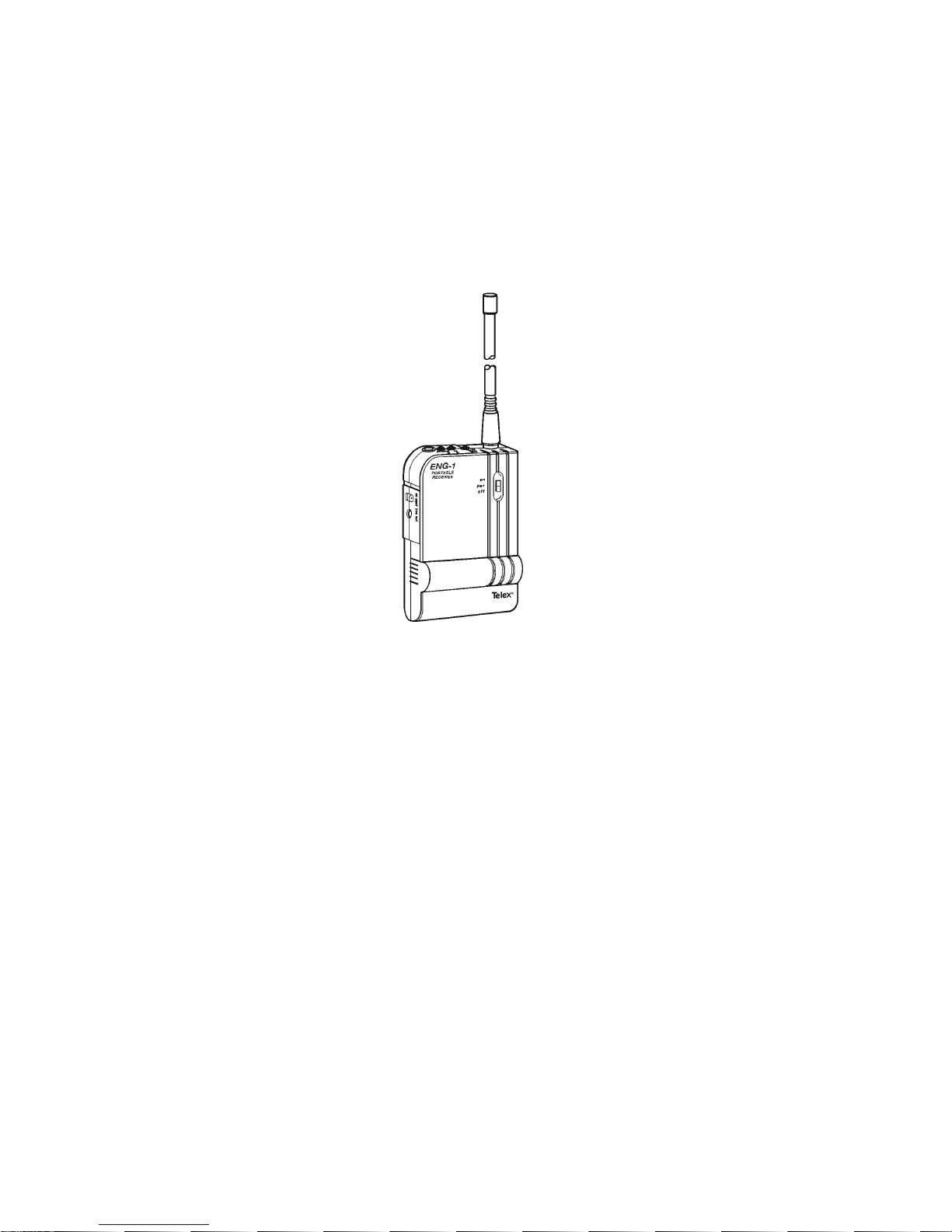
Antenna: A molded VHF antenna is supplied with the ENG-1. This
antenna is matched to the receiver frequency of your unit.
CAUTION:
DO NOT Grip the antenna whileattached to the ENG-1
case. Using the Antenna as a “Handle” may cause
damage to the ENG-1 Receiver.
BeltClip: The beltclip canbe removed forapplication ofthe supplied
“adhesive backed Velcro: for application to a camera or other
equipment.
ENG-1 Set-up
Power\LowBatteryIndication: Install a fresh alkalinebattery in the
ENG-1receiveror connect theENG-1toany filtered 8-24VDCsource
via the DC jack on the side of the unit. Turn the receiver power on.
Note that the low battery (yellow) LED should flash on. If the battery
LED stays illumunated, this indicates a weak battery. If the battery
LED does not come on at all, the battery is dead.
-7-
Page 10

Antenna: Screw the antenna (hand tighten) onto the receiver.
For best performance, place the unit in “Clear and Visible” sight of
the transmitter.
Audio Output: Insert a 3.5mm O.D. plug into the Line Output jack
on the side of the ENG-1. Adjust the Line Output control located in
the battery compartment, to the desired level output your system
requires.
-8-
Page 11

Interference:As with any radiodevice, interference can occurat any
time. There are basically two types of interference, mild and severe.
Before usingthe ProStar System,Telexrecommends thatyou monitor
the channel for interference. To do so, install your ENG-1 receiver
only, in the desired location. DO NOT turn on any other receiver or
transmitter at this time.
TheProStar systemis shippedpre-adjustedfor theaverage installation
and will normally not require any further adjustment.
Mild interference will cause the ENG-1 receiver’s “tx on” green LED
to be on or flicker, along with audible noise. This type of interference
can usually be “squelched out” by advancing the squelch control
located inside the battery compartment, clockwise until the LED goes
off. If the squelch controlcannot cause the LEDto go off,check to see
if a transmitter has been accidentally left on.
CAUTION:
Advancing the squelch control too far can result in short
operating range.
Severe interference will cause the “tx on” green LED to stay on all the
time. Audible interference can be present or if the interfering signal is
simply a “carrier”, no audio will be heard. If the squelch control is
advanced full on and the “tx on” light is still lit, the interference is
severe and an alternate frequency/channel should be used.
If the interference is mild, a reduction in the level of interference can
often be had by simply moving the receiver to a different location.
Monitor the channel periodically for interference.
NOTE: If, after adjusting the ENG-1 or Telex transmitter and the
audio is weak, or distorted, this would indicate a level mismatch
beween the ENG-1 and the amplifier/mixer. This problem must be
corrected at the amplifier/mixer.
-9-
Page 12

FCC INFORMATION
The Telex Model ENG-1 receiver has notification under Part 15 of
the Federal Communications Commission. Licensing of Telex
equipmentisthe user’sresponsibilityandlicensabilitydepends upon
the user’s classification, and frequency selected. Telex strongly
urges the user to contact the appropriate telecommunications
authority before ordering and choosing frequencies.
CAUTION
Any changes or modifications made to the above
equipment could void the user’s authority to operate the
equipment.
-10-
Page 13

WARRANTY SERVICE INFORMATION
If your receiver or transmitter should need servicing under the warranty, please
contact:
Warranty Service Department
TELEX COMMUNICATIONS, INC.
8601 East Cornhusker Highway,
P.O. Box 5579,
Lincoln, Nebraska 68505-5579 U.S.A.
Phone: (402) 467-5321 or 465-7021
All claims of defect or shortage should be sent to the above address.
When returning items for service, you must provide date and proof of
purchase, such as a copy of the sales receipt, to establish warranty. A
letter should be included outlining all symptoms and claimed defects.
Informat
include your phone number and return address in case our service technicians
need to contact you.
Units that have been modified cannot be accepted for repair.
Include all information requested by the Service Center. Then pack the unit as
follows:
Check the unit to see that allparts and screws are in place. Then wrap it in heavy
paper or put it in a plastic bag. If the original carton is not available, place the
unit in a strong carton that is at least six inches bigger in all three dimensions
than the unit. Fill the carton equally around the unit with resilient packing
material (shredded paper, excelsior, etc.). Seal it with gummed paper tape, tie
it with a strong cord, and ship it by prepaid express, United Parcel Service or
insured parcel post to the Hy-Gain Service Center.
ionon how theequipmentwas installed and used isveryhelpful. Please
It is very important that theshipment be well-packedand fully insured. Damage
claims must be settled between you and the carrier and this can delay repair and
return of the unit to you.
Telex reserves the right to make changes in design and improvement on its
product without assuming any obligation to install the same on any of its
products previously manufactured. Further Telex reserves the right to ship new
and/or improved products which are similar to the form, fit and function of
products originally ordered.
-11-
Page 14

TELEX COMMUNICATIONS, INC. • 9600 Aldrich Ave. So., Minneapolis, MN 55420
PN 802371-1 24 MAY 1995
R
 Loading...