

Page 1
®
Telex
User Instructions
Listen
Call
Listen
Talk
Call
Listen
™
Talk
Call
Listen
Talk
Call
Talk
EMS4000
RESET
5
3
6
4
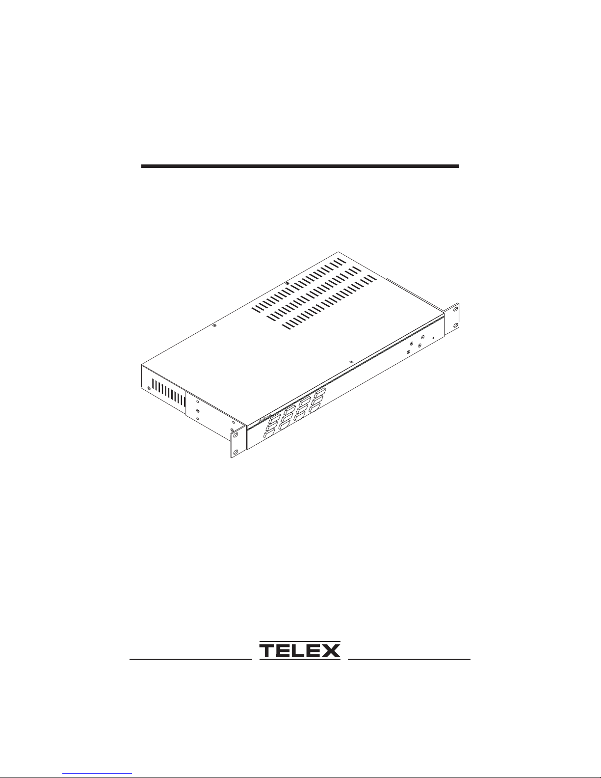
Model EMS4000
Four-channel Expansion Master
Station and Power Supply
Audiocom
®
Intercom Systems
®
Page 2

FCC Statement
This equipment uses and can radiate radio frequency energy that may cause in
terference to radio communications if not installed in accordance with this man
ual. The equipment has been tested and found to comply with the limits of a
Class A computing device pursuant to Subpart J, Part 15 of FCC Rules which
are designed to provide reasonable protection against such interference when op
erated in a commercial environment. Operation of this equipment in a residential
area may cause interference which the user (at his own expense) will be required
to correct.
This product meets Electromagnetic Compatibility Directive 89/336/EEC.
-
Introduction.
Thank you for purchasing the Audiocom EMS4000 Four-channel Expansion
Master Station and Power Supply. We hope the many design features of this
product will satisfy your intercommunication requirements for many years to
come. To get the most out of the EMS4000, please take a few moments to look
-
-
through this booklet before using the Intercom Expansion Station for the first
time.
2
Page 3

Table of Contents
Description .............4
Features ..............5
Installation .............7
Unpacking ............7
Configuration Pre-check ..........7
Mounting Configurations .........10
Connection Notes ...........14
Cables .............14
Power-Up ............15
Sidetone Adjustments ..........15
Operation .............15
Specifications ............16
Factory Service and Parts Information .......18
3
Page 4
Audiocom®
Description
The EMS4000 adds four powered intercom channels to an MS2000 Master Station,
and it provides talk, listen and call buttons for the added channels. Up to 4 EMS4000
Expansion Master Stations may be connected to the MS2000 to add up to 16 chan
-
nels (18 channels total). The MS2000 microphone is used to talkback to the
EMS4000 channels, and the MS2000 speaker is typically used for listening. How
-
ever, there are also separate speaker jacks on the back panel of the EMS4000 for in
dependent monitor speakers, if desired. There are also 4 additional program inputs
on the back of the EMS4000, 1 for each added channel.
The MS2000 / EMS4000 combination can be used as a simple, multi-channel intercom
user station. In this configuration, the program inputs (and possibly the PA output of
the MS2000) are most likely not used, and the station operator has only talk, listen and
call capability. It is also possible that advanced features of the MS2000, such as Mic
Kill Send, might be turned off. Alternatively, the MS2000 / EMS4000 can be used as a
master station. In this application, one or more program inputs and the PA output may
be connected, and the program signals to the intercom channels can be turned on or off
from the MS2000. Additionally, the Mic Kill Send feature can be enabled, and micro-
phones on any channels may then be turned off from the MS2000.
-
®
Listen
Call
3456
Talk
123
100-240VAC 60/50 HZ
6 7 8 9 10 11
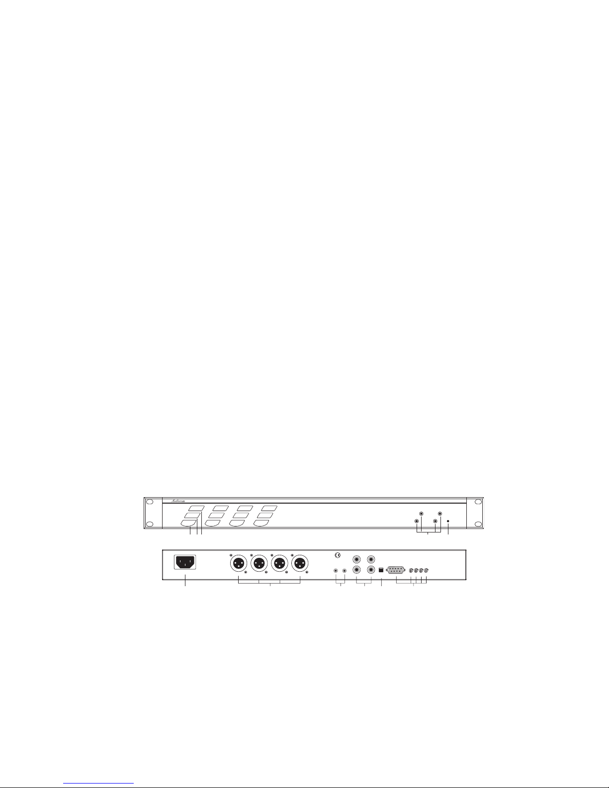
Figure 1. ES4000A Reference View (See numbered features on next page)
4
Listen
Listen
Call
Call
Talk
Talk
CHN3 CHN4 CHN5 CHN6
Listen
Call
Talk
CLASS2 WIRING 1.5 A 24 VDC
EXPINEXP
EMS4000
345
6
Reset
45
SPEAKER
5
3
OUT
4
LINE LEVEL
1VRMS
PROGRAM
INPUTS
6
BAL-OUT
UNBAL-IN
PGMVOL
3456
TELEX COMMUNICATIONS,INC.
MADE IN USA
Page 5

Features
1. Intercom Talk Keys: Momentary or latching (hands-free) operation possible.
2. Call Keys: Used to call intercom channels and to indicate incoming calls.
3. Intercom Listen Keys: Momentary or latching operation possible.
4. Channel Power Status Indicators: The indicators are green for normal operation
and change to red if there is a short circuit or overload condition on a power out
put line. If an indicator turns red, either disconnect the corresponding channel
connector or turn off the intercom system and locate the problem before resum
ing operation
5. Reset Button: Used to resume normal operation after an overload condition has
been corrected.
6. Universal AC Power Connector: Accepts a variety of international power cord
types.
7. Intercom Channel Connectors: These connectors provide the power and audio
connections for each of the 4 intercom channels.
8. EXP IN and EXP OUT Connectors: The EXP IN connector receives the micro-
phone audio signal from the MS2000, and it sends the monaural mix of the four
EMS4000 channels to the MS2000 speaker or headset. The EXP OUT connector
connects to the EXP IN connector of an additional EMS4000. Up to 4 EMS4000
Expansion Master Stations may be daisy chained with the EXP IN and EXP
OUT connectors. An EXP IN/OUT cable is supplied with each EMS4000.
-
-
9. SPEAKERS: Usually, the listen mix of all 4 EMS4000 channels is sent to the
MS2000 speaker or headset via the EXP IN connector. Alternatively, speakers
may be connected to one or more of the speaker outputs of the EMS4000.
10. BAL / UNBAL Switch: This selector switch sets the EMS4000 for compatibility
with either Audiocom or Clear-Com* channel connector pin-outs, channel
power requirements, and call signaling requirements. Important! The internal
switches S200 and S600 must be set the same as the back panel BAL/UNBAL
switch.
* Brand names mentioned are the property of their respective companies.
5
Page 6
Audiocom®
11. Program Inputs Connector and Trimmers: Each intercom channel has its own
program input and level adjust trimmer. For each program input, there is an inter
nal jumper which routes the program either to the intercom channel only, or to
both the intercom channel and the MS2000 headset or speaker (default setting).
Additionally, the program signal to the intercom channel may be turned on or
off via the MS2000 front panel programming. There is also an internal program
interrupt DIP switch which selects either automatic program interrupt when the
station operator activates a channel's talk key, or no program interrupt during
talk. The EMS4000 program inputs connector may be broken out to common
3-pin XLR audio cables using an optional XP-4PGM Breakout Panel.
-
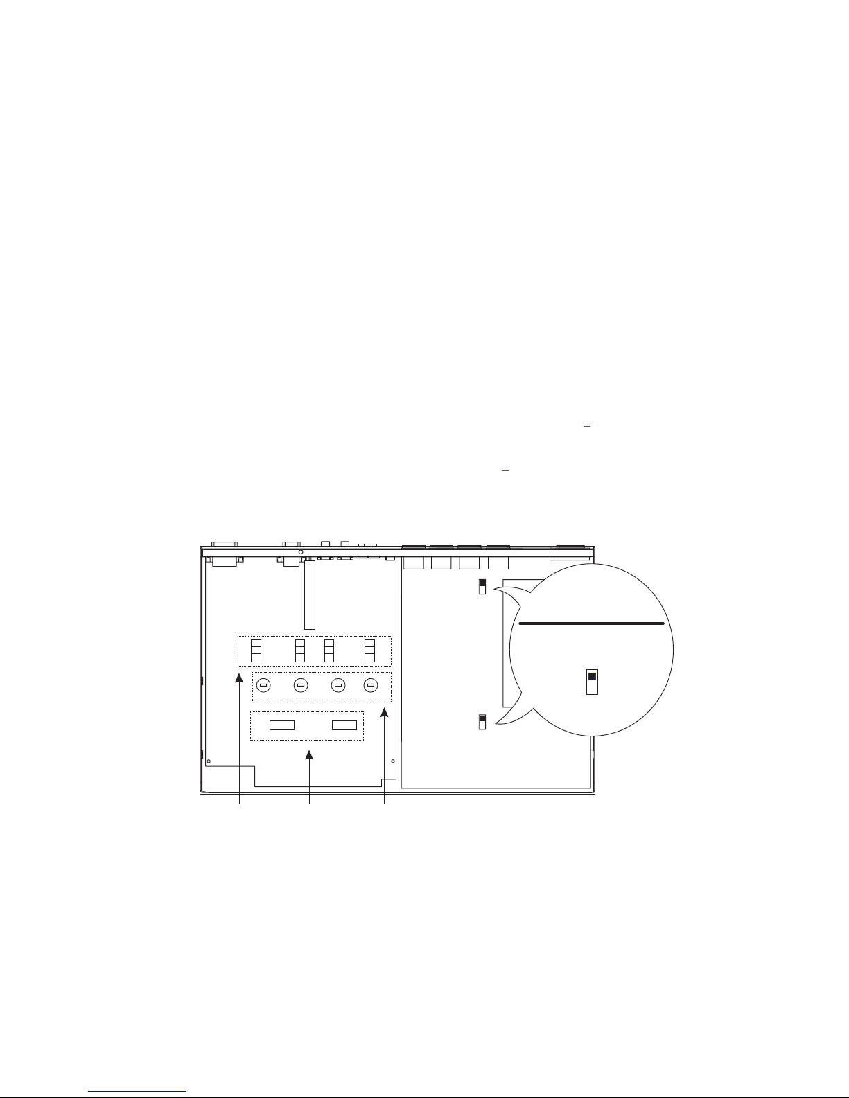
12. Configuration Switches, Jumpers and Sidetone Controls (Figure 2
). These let
you customize the operation of the EMS4000 to match your intercom system re
quirements. See “Configuration Pre-check”, page 7
BAL / UNBAL
SW2
321
J18
Ch 5
321
J21
Ch 6
Sidetone
Trimmers
Program
Listen
Jumpers
321
J15
Ch 3
SW1
DIP Switches
321
J16
Ch 4
SW3
, for details.
S600
S200 & S600
MUST BE SET THE SAME
AS SW2 ON THE BACK PANEL.
FACTORY SETTING BAL
(AUDIOCOM)
S200
UNBAL
(CLEAR-COM)
BAL
-
Figure 2. Locations of configuration switches, jumpers, and sidetone controls.
(Top cover removed.)
6
Page 7

Installation
Unpacking
The EMS4000 is supplied with the following items. Contact the shipper or your
Audiocom dealer immediately if anything is damaged or missing. Detach and fill out
the registration card and return it to Telex to properly register your intercom station.
Quantity Description
1 EMS4000 Expansion Master Station and Power Supply
1 Warranty and registration card
1 User Instructions
1 EXP IN/OUT Cable, with 1/8-inch (3.5 mm) phone plugs
2 Rack Mount Cosmetic Covers
WARNING
The following instructions are for use by qualified personnel
only. To avoid electric shock, do not remove the cover un
less you are qualified to do so.
AVERTISSEMENT
Les instructions qui suivent s'adressent uniquement a un
technicien qualifie. Pour evite des chocs electriques, ne pas
ouvrir le boitier, a moins d'y entre habilite.
Configuration Pre-check
Before making connections, read the configuration notes that follow, and make sure
that all switches and jumpers are properly set for your intended usage. Locations of
configuration switches and jumpers are shown in Figure 2
. Only the DIP switches
and jumpers require internal access. If access is required, remove 3 screws from the
top cover and 3 screws along the bottom edge from each side.
DIP Switches
DIP switches and their default settings are listed in Table 1, page 8. The following
paragraphs provide additional details.
7
Page 8

Audiocom®
Table 1. Configuration Switch Settings
Switch
Number
SW1-1 Program Interrupt, Ch 6
SW1-2 Program Interrupt, Ch 5
SW1-3 Program Interrupt, Ch 4
SW1-4 Program Interrupt, Ch 3
SW1-5 Audiocom Call Send, Ch 3*
SW1-6 Audiocom Call Receive, Ch 3*
SW1-7 Audiocom Call Send, Ch 4*
SW1-8 Audiocom Call Receive, Ch 4*
Important! All three switches must be set the same. Factory default is Balanced.
SW2 Audiocom or Clear-Com
S200
S600
SW3-1 Audiocom Call Send, Ch 5*
SW3-2 Audiocom Call Receive, Ch 5*
SW3-3 Audiocom Call Send, Ch 6*
SW3-4 Audiocom Call Receive, Ch 6*
SW3-5 Not used
SW3-6 Not used
SW3-7 Not used
SW3-8 Not used
Audiocom or Clear-Com
Description Settings Default
DIP Switch SW1 (Internal)
On (Closed): Enabled
Off (Open): Disabled
On (Closed): Enabled
Off (Open): Disabled
On (Closed): Enabled
Off (Open): Disabled
On (Closed): Enabled
Off (Open): Disabled
On (Closed): Enabled
Off (Open): Disabled
On (Closed): Enabled
Off (Open): Disabled
On (Closed): Enabled
Off (Open): Disabled
On (Closed): Enabled
Off (Open): Disabled
Balanced (BAL) - Unbalanced (UNBAL) Operation
operation
operation
DIP Switch SW3 (Internal)
Out: Audiocom (Balanced)
In: Clear-Com (Unbalanced)
BAL: Audiocom
UNBAL: Clear-Com
On (Closed): Enabled
Off (Open): Disabled
On (Closed): Enabled
Off (Open): Disabled
On (Closed): Enabled
Off (Open): Disabled
On (Closed): Enabled
Off (Open): Disabled
On (Closed): N/A
Off (Open): N/A
On (Closed): N/A
Off (Open): N/A
On (Closed): N/A
Off (Open): N/A
On (Closed): N/A
Off (Open): N/A
Setting
Off
Off
Off
Off
On
On
On
On
Out (BAL)
BAL
On
On
On
On
Don’t care
Don’t care
Don’t care
Don’t care
These switches apply only when the BAL/UNBAL switches SW2 (back panel), S200 and
*
S600 (both internal) are set to the BAL position for Audiocom usage (see Figure 2
the switches are set to the UNBAL position, call send and receive are always enabled.
8
). When
Page 9

Program Interrupt DIP Switches
Each intercom channel has a dedicated program input. These can be used to feed
background music, mix-minus audio (for broadcasting usage) etc. to the intercom
channels. If external program sources will be connected to the EMS4000, you have a
choice of whether or not you want the program audio to interrupt (shut off) on the in
tercom channel while the MS2000A/EMS4000 station operator is talking.
Audiocom Call Send and Receive DIP Switches
-
By default, all channels of the EMS4000 can send and receive Audiocom call sig
nals. You can disable call send or call receive capability for selected channels if de
-
-
sired.
Balanced/Unbalanced Switches
The switches are located on the back panel ( SW2) and internal (S200 & S600).
These switches must be set to the balanced (BAL) position for use with an
Audiocom Intercom System. Set the switches to the unbalanced (UNBAL) position
when using the MS2000A / EMS4000 with a Clear-Com Intercom System. All
switches must be set the same.
Direct Program Listen Enable / Disable Jumpers
By default, each program input can be heard by intercom stations on the correspond-
ing intercom channel. (This can be turned on or off for each program input via the
MS2000 front panel programming. See "Turning the Program Inputs On and Off" in
the Operation section of the MS2000 User Instructions.) Additionally, all program
signals can be heard directly in the MS2000 speaker or headset, and each program is
output at the corresponding speaker jack on the back of the EMS4000. To disable di
rect program listening for a program input, reset the appropriate jumper as shown in
Table 2
. Locations of the jumpers are shown in Figure 2, page 6.
-
Table 2. Direct Program Listen Enable / Disable Jumpers
Jumper Description Settings for All Jumpers
J15 Program 3 direct to Headset or Speaker
J16 Program 4 direct to Headset or Speaker
J18 Program 5 direct to Headset or Speaker
J21 Program 6 direct to Headset or Speaker
Pins 2&3 Shorted: Enable
Pins 1&2 Shorted: Disable
9
Page 10
Audiocom®
Audiocom / RTS Select Jumpers.
These internal jumpers (W102 through W802) are for special applications which are
not applicable to the EMS4000. Leave the jumpers in the factory default position
(pins 2 & 3 shorted).
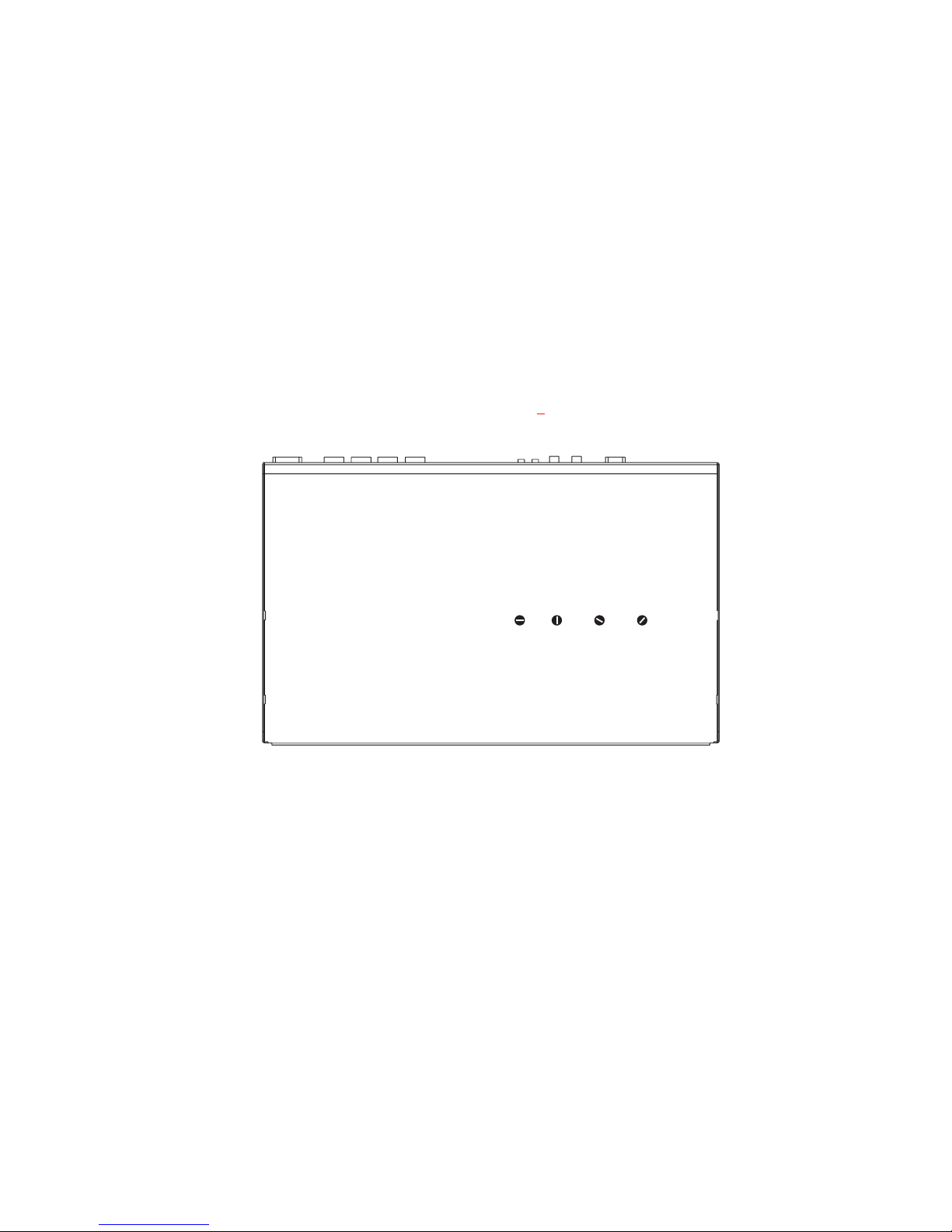
Sidetone Trimmers
These trimmers are normally adjusted after all components are connected, and they
can be accessed through the bottom cover (Figure 3
). Refer to the MS2000 User
Manual for the sidetone adjustment procedure.
Ch 5
Sidetone
Ch 6
Sidetone
Figure 3. Sidetone Trimmer Access on Bottom of ES4000A
Sidetone
Ch 3
Sidetone
Ch 4
Mounting Configurations
The EMS4000 mounts in a standard 19 inch equipment rack and is 1 rack unit high.
Install the 2 supplied rack mount cosmetic covers when installing the EMS4000 in
the rack.
When rack mounting components, you may not be able to access the sidetone
☞
trimmers after the components have been mounted. In this case, you can position
the components in the rack and make all required connections. Then, adjust the
sidetone trimmers before installing and tightening all rack mount screws.
10
Page 11

PGM
OANO
000
2IN
9 109
PGM
1IN
PA
OUT
Note: For further informa
tion about the cable num
bers, see page 14
.
-
-
CH 1-2
XP-USPG
PGM
PGM
5IN
6IN
9 99
CH 3 - 6
XP-4PGM
PGM
PGM
9IN
10 IN
9 999
CH 7 - 10
XP-4PGM
7
7
PGM
4IN
FRONT
PGM
8IN
FRONT
FRONT
BACK
PGM
3IN
9
BACK
PGM
7IN
BACK
CH 1-2
MS2000
100-240VAC60/50 HZ
TELEXCOMMUNICATIONS,INC.
PUSH
®
Telex
MADEINUSA
CHN1/ 2 CHN1/ 2
8
5
CH 3-6
EMS4000
1 1
1
100-240VAC60/50 HZ
CH 7-10
EMS4000
100-240VAC60/50 HZ
CHN3 CHN4 CHN5 CHN6
CLASS2WIRING 1.5 A 24 VDC
11
1
CHN3 CHN4 CHN5 CHN6
CLASS2WIRING 1.5 A 24 VDC
7
PROGRAM
INPUTS
SPEAKERS
LINELEVEL
1VRMS
EXP
P.A.
OUT
PUSH
2
VOL
PGM1
1
BAL-OUT
CHN1
UNBAL-I N
1
TO TW-7W SPLITTERS
(FOR HOME RUN CONNECTION)
OR TO A STRING OF
INTERCOM STATIONS
(DAISY CHAIN CONNECTION)
1
5
3
EXPINEXP
(FOR HOME RUN CONNECTION)
(DAISY CHAIN CONNECTION)
PROGRAM
OUT
INPUTS
6
4
BAL-OUT
LINELEVEL
UNBAL-IN
1VRMS
TO TW-7W SPLITTERS
OR TO A STRING OF
INTERCOM STATIONS
1
5
3
EXPINEXP
PROGRAM
OUT
INPUTS
6
4
BAL-OUT
LINELEVEL
UNBAL-IN
1VRMS
VOL
PGM2
1
PGMVOL
3456
PGMVOL
3456
PUSH
CHN2
TELEXCOMMUNICATIONS, INC.
MADEIN USA
TELEXCOMMUNICATIONS, INC.
MADEIN USA
CH 1
CH 2
CH 3
CH 4
CH 5
CH 6
CH 7
CH 8
CH 9
CH 10
5
Note: A BOP-1000 Rack Mount Plate may
be used to rack mount 4 XP-4PGM or
XP-USPG breakout panels.
Figure 4. Master station with multiple EMS4000 Expansion Stations. This con
figuration provides all of the channel power and program input connections for
10-channel intercom station. It also interfaces the PA jack of the MS2000 to a stan
dard, 3-pin XLR audio cable. Note: The MS2000 includes a speaker and is typically
used for intercom listening, with a gooseneck microphone connected to the
MS2000 for talk-back. Alternatively, a headset with a microphone may be used.
T
5
THER EMS4
-
-
11
Page 12

Audiocom®
O
S
EGM MIC
FRONT VIEW
TM
®
Listen
Call
3456
Talk
100-240VAC60/50 HZ
100-240VAC 60/50 HZ
Volum e
Listen
Call
Talk
®
Telex
TELEXCOMMUNICATIONS, INC.
MADEIN USA
Vox
Headset
PA
PanelMic
AllTalk
Listen
Call
Talk
CHN3 CHN4 CHN5 CHN6
CLASS2 WIRING 1.5 A 24VDC
Listen Listen
MicKill
Call Call
Talk Talk
12
MS2000
Listen
Call
Talk
EMS4000
BACK VIEW
PUSH
CHN1 / 2 CHN1 / 2
PROGRAM
MS2000
1
Combine
2
Isolate
EMS4000
6
PUSH
CHN2
TELEXCOMMUNICATIONS, INC.
MADEIN USA
Reset
Reset
Volum e
345
INPUTS
2
SPEAKERS
LINELEVEL
1VRMS
1
EXP
P.A.
OUT
5
3
EXPINEXP
OUT
4
LINELEVEL
1VRMS
PUSH
VOL
PGM1
BAL- OUT
CHN1
UNBAL- IN
1 1
5
PROGRAM
INPUTS
6
BAL-OUT
UNBAL-IN
VOL
PGM2
PGMVOL
3456
CH 1 CH 2 CH 3 CH 4 CH 5 CH 6
ADDITIONAL INTERCOMSTAT ION
T
Figure 5. 6 Channel Daisy Chain Configuration This configuration adds four ad
ditional channels to the MS2000. All intercom channels will be monitored through
the MS2000 internal speaker.
12
Note: For further informa
tion about the cable num
bers, see page 14
-
-
.
-
Page 13

FRONT VIEW
SSHO
OSS
Note: For further informa
tion about the cable num
bers, see page 14
.
-
-
TM
Volum e
®
Listen
Listen
Call
Call
3456
Talk
Talk
BACKVIEW FOR HOME-RUN CONNECTION
TELEXCOMMUNICATIONS, INC.
MADEIN USA
100-240VAC60/50 HZ
100-240VAC60/50 HZ
TW-7W
1 11111 1
CH 3
Headset
MicKill
Vox
PA
PanelMic
Talk Talk
AllTalk
Listen
Listen
Call
Call
Talk
Talk
CHN1 & 2 CHN1& 2
CLASS2WIRING 1.5A 24VDC
CHN3 CHN4 CHN5 CHN6
CLASS2 WIRING1.5 A 24 VDC
1*
MS2000
Listen Listen
Call Call
12
EMS4000
PROGRAM
INPUTS
SPEAKERS
2
LINELEVEL
1VRMS
1
EXP
P.A.
BAL- OUT
OUT
MADEIN USA
UNBAL- IN
5
5
3
EXPINEXP
OUT
6
4
LINELEVEL
1VRMS
TW-7W
1 11111 1
CH 5
MS2000
1
Combine
2
Isolate
EMS4000
345
6
TELEXCOMMUNICATIONS,INC. MADE IN USA
PUSH
CHN2
TELEXCOMMUNICATIONS, INC.
MADEIN USA
Reset
Reset
TO ADDITIONAL
TW-7W SPLITTERS
CH 1
CH 2
Volum e
PUSH
VOL
VOL
PGM1
PGM2
CHN1
1
1
PROGRAM
INPUTS
PGMVOL
BAL-OUT
3456
UNBAL-IN
1*
TW-7W
1 11111 1
CH 4
TO ADDITIONAL INTERCOM STATIONS
* KEEP CABLES FROM MS2000 TO
TW-7W A
Figure 6. 6 channel Home-run configuration: With a headset connected to the
front panel of the MS2000 the DIP switches must be set to monaural operation (de
fault setting) so that all intercom channels are heard in the monaural headphones
(binaural headphone operation is not supported). Refer to the MS2000 User
Instructions “Monaural or Binaural Operations DIP Switches”.
1*
1 11111 1
RT ASP
IBLE.
TW-7W
CH 6
1*
Note: A BOP-1000 Rack
Mount Plate may be
used to mount 2 TW-7W
splitters.
-
13
Page 14

Audiocom®
Connection Notes
Typical connections for the MS2000/EMS4000 are shown starting with Figure 4
page 11
. Select the configuration which most closely matches your intended usage.
,
Cables
The numbers below correspond to the cable numbers in the connection drawings on
the previous pages.
1. 1-channel intercom cable. Sold separately. Use Telex "ME" cables, below. Or,
build per Figure .
ME-25: 25' (7.6 m) cable with Male and Female 3-pin XLR connectors.
ME-50: 50' (15.2 m) cable with Male and Female 3-pin XLR connectors.
ME-100: 100' (30.4 m) cable with Male and Female 3-pin XLR connectors.
2. 2-channel intercom cable. Sold separately. Use Telex "ME /2" cables, below.
Or, build per Figure .
ME-25/2: 25' (7.6 m) cable with Male and Female 6-pin XLR connectors.
ME-50/2: 50' (15.2 m) cable with Male and Female 6-pin XLR connectors.
ME-100/2: 100' (30.4 m) cable with Male and Female 6-pin XLR connectors.
3. Y adapter cable. Sold separately. Use Telex CA-23-16. Or, build per Figure .
4. 3 ft (0.91 m) speaker cable with RCA plugs. One supplied with each SPS2000A,
SPK-1000, and SPK-2000.
5. 18" (457 mm) EXP IN/OUT cable, stereo miniplug to stereo miniplug. One sup
plied with each ES4000A.
6. 18" (457 mm) CHANNEL OUTPUT cable, 15-pin Male Dsub to 15-pin Male
Dsub. One supplied with each ES4000A.
7. Shielded patch cable, 9-pin Male Dsub to 9-pin Female Dsub. Customer local
purchase: available at Radio Shack, etc. Note: All pins must be connected
straight through: do not use an RS232 computer cable!
8. Shielded patch cable, stereo miniplug to stereo miniplug. Customer local pur
-
chase. Available at Radio Shack, etc.
14
-
Page 15

9. Shielded audio cable. Must have male 3-pin XLR connector at one end for con
nection to the XP-USPG or XP-4PGM program inputs. Pin-out for program in
puts is as follows:
Pin 1: common
Pin 2: + program input
Pin 3: - program input
-
-
10. Shielded audio cable. Must have male 3-pin XLR connector at one end for con
nection to the XP-USPG PA output. Pin-out for PA output is as follows:
Pin 1: common
Pin 2: + PA output
Pin 3: - PA output
11. 18" (457 mm) CHANNEL OUTPUT cable, 15-pin Male Dsub to 15-pin Female
Dsub. One supplied with each XP-ES4000A.
Power-Up
Plug in the power cord. The EMS4000 channels power-up identically to channels 1
and 2 of the MS2000. Refer to the MS2000 User Instructions for all power-up infor-
mation. The MS2000 and EMS4000 can be powered up in any order.
Sidetone Adjustments
Use the sidetone adjustment procedure as described in the MS2000 User Instruc
tions, except substitute channel 3, channel 4, etc. The locations of the MS4000
sidetone trimmers are shown in Figure 3
.
-
Operation
-
The EMS4000 channels operate identically to channels 1 and 2 of the MS2000. Re
fer to the MS2000 User Instructions for all operating information.
-
15
Page 16

Audiocom®
Specifications
General
Power Requirements:
AC Input: 100-240 VAC, 50/60 Hz
Channel Power: 24 VDC nominal (12 to 30 VDC) 65 to 150 mA
Local Power (with PS-L Wall-pack Power Supply or equivalent): 14 to 15 VDC
Current: 65 mA, quiescent; 150 mA maximum
Dimensions: 1.75" (44.5 mm) high, 19" (483 mm) wide, 10.31" (261.9 mm) deep
Weight: approximately 4.5lb (2kg)
Environmental Requirements:
Storage: -20°Cto80°C; 0% to 95% humidity, non-condensing
Operating: -15°Cto60°C; 0% to 95% humidity, non-condensing
PROGRAM INPUTS Connector
Input Level: 100mV maximum
Voltage Gain: 25 ±3 dB
Output Level (to intercom channel): 1.0 Vrms nominal, 2.3 Vrms max.
Input Impedance: 75 kohm
Common Mode Rejection: Greater than 50 dB
Connector Type: DB9F Female, 9-pin D-subminiature
Pin 1: Common
Pin 2: Channel 3 program in low
Pin 3: Channel 4 program in low
Pin 4: Channel 5 program in low
Pin 5: Channel 6 program in low
Pin 6: Channel 3 program in high
Pin 7: Channel 4 program in high
Pin 8: Channel 5 program in high
Pin 9: Channel 6 program in high
Intercom Channels, Balanced Mode (All BAL / UNBAL switches set to BAL position)
Output Level: 1 Vrms nominal
Input Impedance: 300 ohms
Bridging Impedance: greater than 10,000 ohms
Sidetone: -40 dB, 35 dB adjustable range
Call Signaling:
Send: 20 kHz ±100 Hz, 0.5 Vrms ± 10%
Receive: 20 kHz ±800 Hz, 100 mVrms
Mic-Kill Frequency:
Send: 24 kHz ±300 Hz, 0.5 Vrms ± 10%
Detect: 24 kHz ±800 Hz, 100 mVrms
Noise Contribution: less than -70 dB
Common Mode Rejection Ratio: greater than 50 dB
16
Page 17

Connector type: One XLR-3M for each channel.
Balanced Configuration Pinouts
Pin 1: Common
Pin 2: Intercom audio low and +24 VDC input
Pin 3: Intercom audio high and +24 VDC input
Intercom Channel, Unbalanced Mode (All BAL / UNBAL switches set to UNBAL position)
Output Level: 1 Vrms ±10%
Input Impedance: 150 ohms
Bridging Impedance: greater than 10,000 ohms ±5%
Call Signaling:
Send: 11 ±3 VDC
Receive: 4 VDC minimum
Connector Type: Uses the same connectors as for balanced mode, above, but with pinouts
modified by BAL/UNBAL switch on back panel as follows:
XLR-3 Unbalanced Configuration Pinouts
Pin 1: Common
Pin 2: +24 VDC input
Pin 3: Intercom audio high
Expansion Input/Output
Connector Type: 1/8" (2.0 m) stereo phone jack
Tip: Talk output
Ring: Listen input
Sleeve: Common
17
Page 18

Audiocom®
Factory Service and Parts Information
When returning equipment for repair include your return address, telephone number
and proof of date of purchase, along with a description of the problem.*
The address for Audiocom equipment returns and parts information is:
Service Department
Telex Communications, Inc.
West 1st Street
Blue Earth, Minnesota 56013 U.S.A.
Telephone: (507) 526-3205
Toll Free: 800-218-2412
Fax: (507) 526-2295
Warranty Repairs - If in warranty, no charge will be made for the repairs. Equipment
returned for warranty repair must be sent prepaid and will be returned prepaid.
Non-Warranty Repairs - Equipment that is not under warranty must be sent prepaid
to Telex. If requested, an estimate of repair costs will be issued prior to service. After
your approval and completion of the repairs, the equipment will be returned on a col-
lect basis. Collect charges may be avoided by sending a signed check for payment in
full along with your signed estimate approval form (shipping charges are included in
the estimate).
* For sales / technical support and system design contact:
Pro Audio Sales Department
Telex Communications, Inc.
9600 Aldrich Avenue South
Minneapolis, Minnesota 55420 U.S.A.
Telephone: (612) 884-4051
Toll Free 800-392-3497
Fax: 800-323-0498
18
Page 19

This page left blank intentionally
19
Page 20

TELEX COMMUNICATIONS, INC. 9600 Aldrich Ave. So., Minneapolis, MN 55420 U.S.A.
9350-7673-000 Rev. A 2/2000
®
 Loading...