

Page 1
®
Te l e x
User Instructions
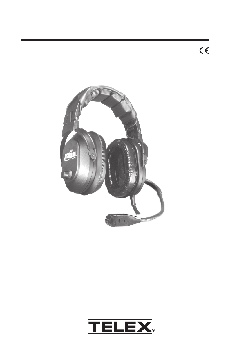
Echelon
100 Headset
Page 2
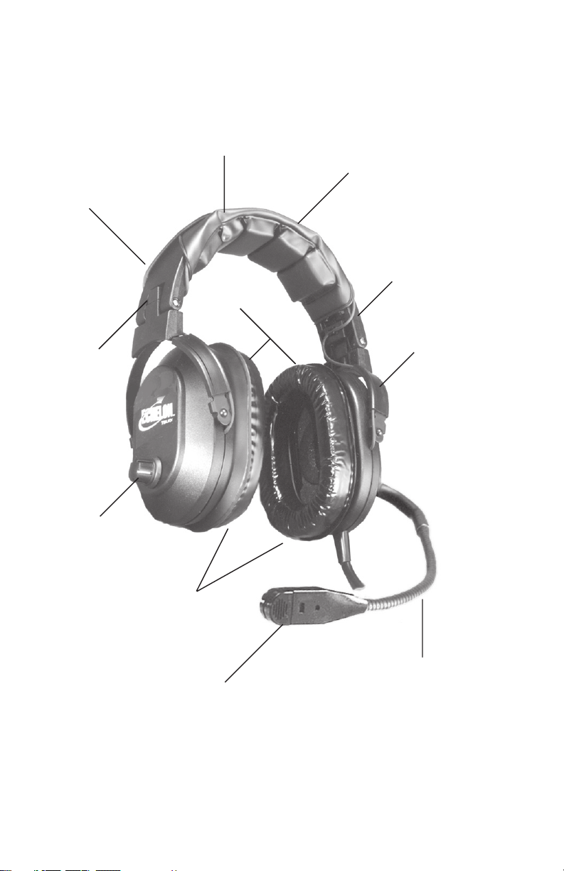
Detented Sliders
Adjust to
Any Size Head
Tension
Adjust Knob
Volume Control
Unique
Design
Replaceable
Ear Cushions
Replaceable
Wide Head Pad
Earcups Pivot on
Two Planes to
Conform to Wearer
Patented Ball and Socket
Jointed Boom Rotates
Overhead for Mic
Placement on Either
Side of Head
Replaceable
Ear Cushions
Noise Canceling
Electret Microphone
Flexible Boom Permits
Precise Mic Placement
Echelon 100 Reference View
Figure 1
Page 1
Page 3

GENERAL DESCRIPTION
The Telex Echelon 100 is a medium-weight noise-reduction headset with amplified,
noise-canceling, electret microphone.
DESIGN FEATURES
(See Figure 1)
Comfortable foam-filled headband pad and ear cushions. The headband pad
evenly distributes the headset weight, with no pressure points, for maximum
wearer comfort. The ear cushions combine comfort and light weight with excellent
acoustic seal. An outer urethane layer ensures long life. Gel-filled ear cushions
are also available for this headset for users who prefer this type. All cushions are
field-replaceable.
Boom Microphone: The boom arm features a sealed ball-and-socket joint and
flexible boom for precise microphone placement on any head size. The boom
rotates overhead for microphone placement on either side of the head. The
microphone cartridge features a noise-canceling electret element. The cartridge
snaps on and off for easy replacement. The microphone amplifier is in the
microphone cartridge. It operates on current supplied by the aircraft radio via the
microphone jack. The amplifier output level is adjustable through an opening in
the earcup.
Cordage: The microphone cordage is protected inside the boom arm. Shielded
wire throughout the headset protects against RFI and EMI. Strain-reliefs on all
cords provide maximum durability.
Page 2
Page 4

OPERATION
Headband Pressure Adjustments
There are three pressure settings. Increasing the pressure will improve the seal
between the earcup and the head for greater noise reduction. To change the
pressure setting, remove the headset and fold the earcup inward as shown, then
rotate the adjustment knob to the desired setting. Repeat for both earcups. Both
sides of the headband should be set to the same pressure setting to keep the
headband properly centered on the head.
HIGH MEDIUM LOW
Boom Microphone Placement
1. Rotate the entire boom overhead to
wear the microphone on either the
right or left side of the head.
2. For best noise canceling, position the
microphone as close to the mouth
as possible and speak in a normal
voice. (See figure 3)
3. When the microphone is not in use,
it may be swung slightly away from
the mouth.
Figure 2
Figure 3
Page 3
Page 5
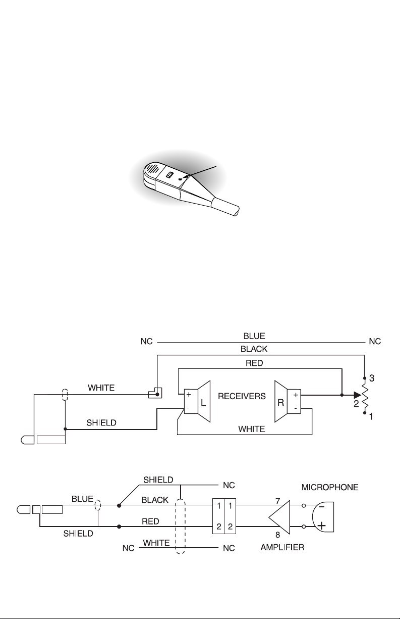
Microphone Gain Adjustment
The microphone gain has been factory-adjusted to the nominal level required for FAA
certification, and it should normally not require readjustment. Readjustment by a
qualified avionics technician is recommended. To access the gain trimmer, insert a
small flat-blade screwdriver through the access hole in the mic assembly. Clockwise
rotation of the trimmer increases gain.
MIC GAIN
ADJUSTMENT
ACCESS
Figure 4
Echelon Wiring Diagram
Page 4
Page 6

Exploded View Parts List (See Figure6)
.oNmetI.oNtraPnoitpircseDytQ
1001-480007edis-mooB,yssApucraE1
2401-480007edis-mooBnoN,yssApucraE1
3001-580007tfeL,revoC1
4101-580007thgiR,revoC1
9000-301008yssArevieceR2
01000-631008yssAenohporciM1
11200-684007yssAmooB1
91000-18307potSmooB1
02000-700007flaHllaB2
12100-490007gnirpSllaB1
22031-47006yssAdroC-Y1
52400-65815gL"4/1x02-4#,etitsalP,wercS1
62030-65815gL"2/1x02-4#,etitsalP,wercS4
72200-041007reniLpuC2
82000-141007revoCrevieceR2
92200-54195tunoDmaoF2
33400-451008yssAdnabdaeH1
43100-431007pilCdroC,noisurtxE2
53100-354007bonKpmalC2
63100-891008dapdaeH1
73700-65436feileRdneB1
83300-720008maoF,noihsuCriaP1
93000-510055•82,droCdaehrevORA
04900-13145lortnoCemuloV,retemoitnetoP1
14100-53435bonKCV1
24000-968007trikSbonK1
34000-71565tresnIbonK1
3000535J
Page 5
Page 7

boom (11) . Place boom stop (19) into slot
on boom (11) . Push inside ball half (20) to hold
boom stop (19) into place. Orient ball half (20)
with cup assembly so that boom will swing
over but not under the earcup assembly (1).
1 NOTE: Slip outside ball (20) around
Figure 6
Page 6
Page 8

SPECIFICATIONS
Receivers:
Type: Dynamic
Frequency Response: 100 Hz - 3.5 kHz
Sensitivity: 95 dB SPL minimum (1 kHz, 1 mW input)
Impedance (at 1 kHz): 150 ohms (receivers wired in parallel)
Microphone and Amplifier:
Element Type: Noise-canceling electret
Frequency Response: 100 Hz - 3.5 kHz
Sensitivity: -48 ±6 dB (ref:1 V/ µbar at 1 kHz with 12 Vdc supply voltage and
470-ohm DC , 150ohm AC load).
Matching Impedance: 50-600 ohms
Gain Adjustment Range: ± 5 dB (clockwise rotation increases gain)
Operating Voltage (supplied by aircraft radio): 8-16 volts dc
Cordage:
Straight Y-cord, 5.5 ft (1.67 m)
Connectors:
PJ-068 equivalent plug for radio mic jack; PJ-055 equivalent plug for radio phone
jack
Weight:
Effective Head Weight: Approximately 15 oz. (425g)
Color: Black
ORDERING INFORMATION
(See Exploded View Parts List for a complete listing of replacement parts)
Headset ...................................................................... Catalog no. 300535-100
Thin-skin foam ear cushions (set of two) .................... Catalog no. 800027-003
Gel-filled ear cushions (set of two) .............................. Catalog no. 800027-002
Head pad .................................................................... Catalog no. 800198-001
Microphone cartridge .................................................. Catalog no. 800136-000
Microphone windscreen ................................................. Catalog no. 57012-001
Model PT-300 Portable Push-To-Talk Switch* ............... Catalog no. 63966-000
* For aircraft without a push-to-talk switch, a portable push-to-talk switch must
be used.
Page 7
Page 9

38109-810 Rev C 7/02
 Loading...