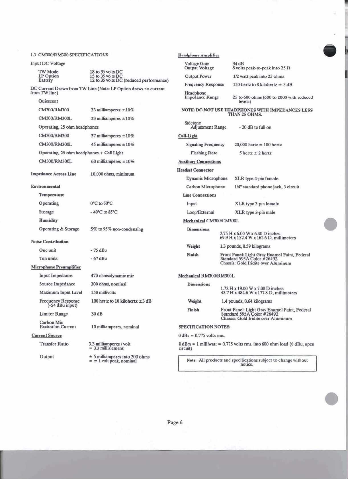
Headset Receptacle: XLR type 4 pin female / Carbon Microphone: 1/4 blanket standard phone insert
Weight (CM300): 69.9 H x 152.4 W x 162.6 D mm; Weight: 1.3 kg 1.59 Power amplifier (T4850): Dimensions Portable: Weight 4 pounds
Measurements Suspenders: 1.72 H x 19.00 W x 7.00 D inches等 (430 mm H x 482.6 mm W x 178 mm D); Weight: 1.4 kg
Coating Applied: Light grey enzyme paint federal standard bow Gold iridite trên aluminum
Frequently Asked Questions
Q: The CM300/RM300 is intercom system compatible with?
A: The CM300/RM300 is intercom system cooperates with full duplex type conference line intercom.
Q: Can a conference line be used by how many users?
A: No more than 75 users are able to connect on one line for a TM conference call.
Q: What Bos II SS profile is supplied the CM300 / RM300?
A: The power supply requirement of the CM300 is connected to 18 to 35 volts DC. ON the other hand, RM 300’s voltage is 15 to 35 volts DC.
Q: Which headsets are compatible with the CM300/RM300?
A: The CM300/RM300 interfaces with both the dynamic and carbon microphone-type of headsets.
Q: What is the optimum temperature for the CM300/RM300?
A: The operating temperature range is from 0 degrees to 60 degrees Celsius.
Q: How is the audio volume regulated on CM300/RM300?
A: CM300/RM300 integrates a volume control knob that modulates the volume in the Headset.
Q: Discuss the features of CM300/RM300.
A: Dual listen, program input, three channels operative, unswitched microphone output, and localized power supply are among the provided features.
Q: Which microphone and headset connectors are suitable?
A: The CM300/RM300 are equipped with the XSLR type 4 pin female connectors for dynamic microphones and quarter inch standard phone jacks for carbon microphones.
User Manual
Page 1
USER
I
MODEL CM300
Console Mount User Station
MANUAL
I
I
MODEL RM300
Rack Mount User Station
I
RTSTM
9350-2643-00
Rev
E
2/01
Page 2
PROPRIETARY NOTICE
The
RTS product information and design disclosed herein
were
originated
by and
are
the property of Telex
Communications, Inc. Telex reserves all patent,
proprietary design, manufacturing, reproduction, use and
sales rights thereto, and to any
except to the extent rights
dcle disclosed therein.
are
expressly
granted
to others.
COPYRIGHT NOTICE
CUSTOMER SUPPORT
Technical questions should
Customer Service Department
RTSfl'elex
12000
Portland Avenue South
Bumsville,
Telephone:
Fax:
(800) 323-0498
be
directed
MN
55337
(952) 884-4051
to:
U.S.A.
Co yright
rigKts reserved. Reproduction in whole or
1994
by Telex Communications, Inc.. All
in
part without
prior written permission from Telex is prohibited.
PATENT NOTICE
This
equipment contains and uses a desi
United States Patent No.
4,358,644:
Sowce for a Multi-terminal Intercom".
employs a two-wire to four-wire
convemr.
embodied in
"A
Elatera1 Current
Ibis
design
UNPACKING AND INSPECTION
Immediately upon recei of the equipment, inspect the
shipping
discrepancies or damage. Should there be
freighi company and t6e dealer at once.
contamer and g e contents carefully for an
anv. noti& the
WARRANTY INFORMATION
RTS products are warranted by Telex Communications.
Inc. to be
for a period of
The sole
to provide,
remedy covered defects appearing in
pre aid
mahnctim or failure
including unreasonable M negligent operation, abuse,
accident, failure to follow
Manual or
associated equi ment, attee at modificadon'and repair
not authorized
with
covered
free
from defects in materials and workmanship
three
years from the
date
of sale.
oblieatim of Telex durine the wamw oeriod is
whout charge,
to
Telex. This waifanty
pans
caused
&d labor necekky to
products
does
not wver any defect,
bevond the
,
~~~-
returned
conhol
insmctions in the Service
tbe
User Manual. defective or imomner
chei
gy Telex,
serial numbers remov
by
this warranty.
shlp mg damage.
e!
or effaced
Products
are
of
Telex.
..
....
not
RETURN SHIPPING INSTRUCTIONS
PROCEDURE FOR RETURNS
If a repair is necessary, contact the dealer where this unit
was purchased.
If
rc
air throu h the dealer is not possible, obtain a
R&N
DO
TO
OBTAINING A
Be
phdne 'number,i person to conkct kgarding the re 'air,
the
pmb em and send number(s).
SHIPPING TO MANUFACTURER FOR REPAIR OR
ADJUSTMENT
All
unitedparcel Service br the best available shipper.
.,
prepaid. The equipment should be shipped in
Dackine carton:
container that 1s rigid
container is used, the equipment should
paper and surrounded with at least four inches o
ixielsior or similar shock-ahsorbine
shi
incrude the Return Authorization.
A&ORIZATION
Customer Service
from:
Depamnent
Telex Communications, Inc.
Telephone:
Fax:
NOT
RETURN ANY
THE
FACTORY WITHOUT
oreoared
to
(877) 863-41 69
(800) 323-0498
EQUIPMENT
DIRECTLY
FlRST
RETURN
mvide the comoanv name. address.
AUTHORIZATION.
type and qgntity of equipment, a description ofthe
shi~ments of RTS ducts should
ifthat
is not available: -use anv suitable
and
of adequatesize. If-a substitute
be
made via
be
wra
material.
the
original
pped
All
in
ments must be sent to the follo&ng addrcss and must
To obtain warranty service, follow the
"Procedure For
for Repair or
Renuns" and "Shipping to Manufacturer
Adjusrment".
procedures entitled
This warranty is the sole and exclusive ex rcss warranty
respect
to
given with
of
the user to determine before purchase
RTS ducts. It is
l!
e resbonsibilitv
that
[hi's prod~~i
is suitable for the user's intended purpose.
WARRANTY.
NEITHER TELEX NOR
THE
DEALER
WHO SUS
RTS PRODUCTS IS LIABLE FOR INCIDENTAL OR
ANY
CONSEQUENTIAL DAMAGES OF
KIND.
Factory Service Department
Telex
Communicabons, Incorporated
West 1st Street
Earth,
MN
56013
Blue
Upon completion of any repair the equipment will
U.S.A.
be
returned vla United Parcel Service or specified shipper
collect.
Page 3
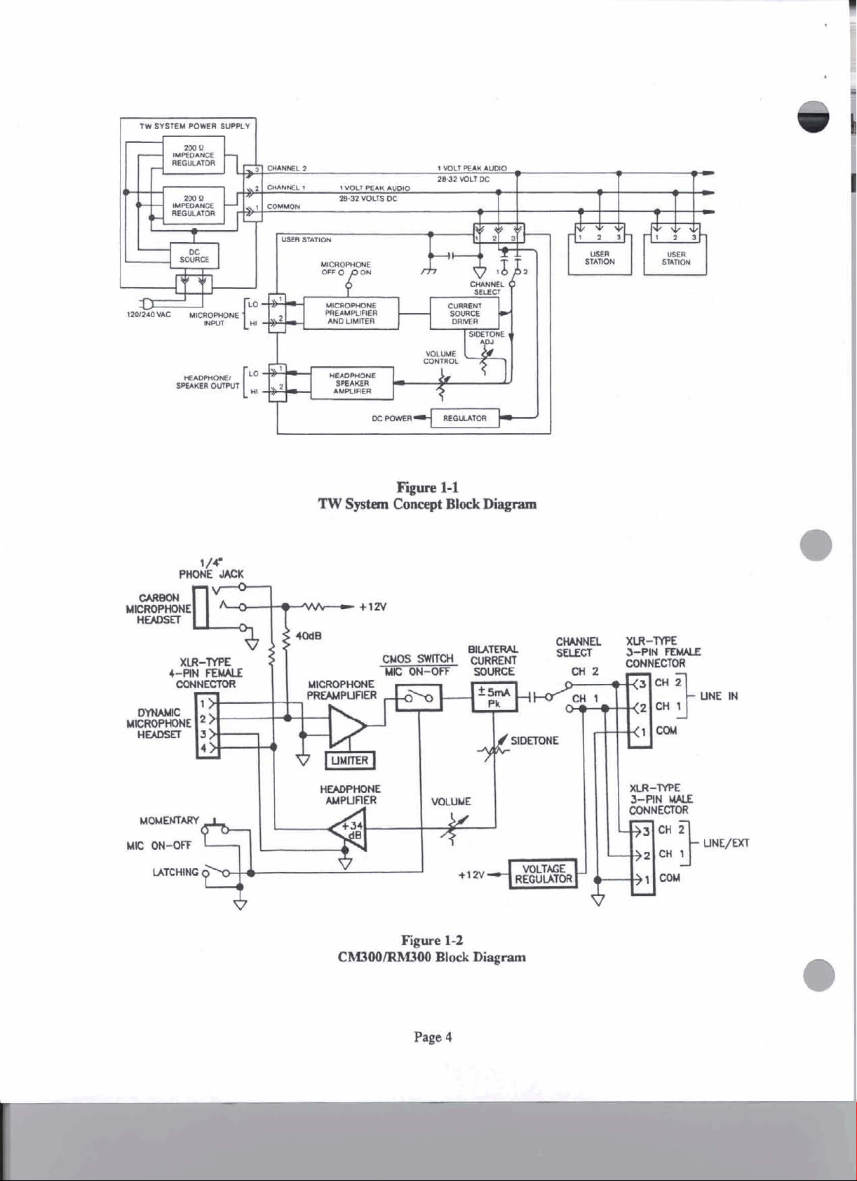
Figure
CM3001RMUW)
1-2
Block
Disgram
Page 4
1.1
DESCRIPTION
The Model CM3W
intercom
two-chmd
designed
intercom
Confereuce
A
people to
conf-
user
station.
intmom
to
he
system.
Line
talk
used
IntMcom
line
intercom
and
listrn
is
a console mount, twhl
The
Model
user
station. The
in a
full
Svstem (Figure
on
a single chaaael.
RMUX)
duplex, wafermce
sysIem
is
a
user
1-1)
allows a
rack
station
group
On
mnmt,
line
of
this
is
c~,allusersanlistrnwhe~anreormmotbsr
users
are
share
Full
talking (eonf&g). Up to 75
the
same
duplex
dermc8
@on
line
allows
(or
two
confcrma
way conversation
usns
bus).
csn
at
the~time,thatis,oneuser~~tassond
The
CM3W/RM3W, with
usertotheinintaoomsystem.
using
the
head& (or a
umnector (optbdly five or
uneeds
"mifour
switch,
select switch.
momentary
tight
to
~011tmIs:
the
momntary
microphone switch
button.
the
type
cable.
the
volum anmoll,
On
a
hedset,
Tbeusertdksandlirtms
hmdsst).
systsm
microphone switch,
the
The
six
pin).
The
using
me
a
CM3w/RM3w
the
latching
Model CM3W/RM300L,
is
replaced
intcrhces
headset
a
umnects
CM3W/RM3W
the
conductor
microphone
md
the
with
hurmn
to
wataiU6
chanael
the
the all
Volume Control
The
volum wntrol on the CM3WlRM3W
range to
ent noise variation, variations in
tivity.
the
headphone amplifier
In
othm
the talker's microphone to
listmas to
condition,


 Loading...