

Page 1
CIA-1000 CALL INDICATOR ASSEMBLY USER INSTRUCTIONS
bbbbbbbbbbbbbbbbbbbbbbbbbbbbbbb
ddddddddddddddddddddddddddddddd
aaaaaaaaaaaaaaaaaaaaaaaaaaaaaaa
ccccccccccccccccccccccccccccccc
bbbbbbbbbbbbbbbbbbbbbbbbbbbbbbb
ddddddddddddddddddddddddddddddd
aaaaaaaaaaaaaaaaaaaaaaaaaaaaaaa
ccccccccccccccccccccccccccccccc
Telex
Channel Select
1
2
CIA-1000
Power
CIA-1000 Call Indicator Assembly
(Top light version for desktop usage.)
General Description
The CIA-1000 Call Indicator Assembly connects to an
Audiocom or RTS TW intercom channel and provides
an attention-getting indicator light for cueing and
paging. The light can be activated by any call button on
the channel. Relay contacts are also included for
activation of an external device along with the light.
The CIA-1000 top-light version can be placed on a
desktop, or mounted on a wall. The front-light version can
be rack mounted with optional Audiocom rack mounts.
Features
■
Choice of red or amber light.
■
Available with top- or front-mounted light. The top-light
version is ideal for desktop or wallmount use. The
front-light version is suitable for rack mounting.
■
Systemselectcontrolforcompatibility with Audiocomor
RTS TW Intercoms.
■
Channel select control for TW channel 1 or 2 select.
■
Line and Loop connectors permit connection within a
chain of intercom stations.
■
AC powered, includes PS-L wallpack (same wallpack as
used for US2000A, ES4000A, SPK-2000).
■
Spring-clampterminals for relayoutput,with normal-open
(NO), common (C) and normal-closed (NC) contacts.
■
Rack-mountable with optional Audiocom rack mount
hardware. Occupies ½-wide rack space.
■
Available in Audiocom black or RTS gray.
528
Telex
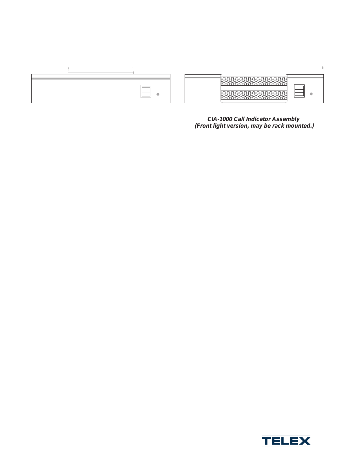
CIA-1000 Call Indicator Assembly
(Front light version, may be rack mounted.)
Specifications
Power Requirements: 12 to 15 VDC, 65 to 150 mA
(supplied by PS-L wallpack)..
Call Detect Frequency: 20 kHz (compatible with
Audiocom and RTS TW call signaling).
Relay
Type: SPDT, with Common (C), Normal-open (NO)
and Normal-closed (NC) contacts.
Contact Ratings: 0.5A at 120 VAC; 1A at 24 VDC;
0.3A at 60 VDC.
Dimensions: 2" (51 mm) high (top-mounted light) 1.75”
(44.5 mm) high (front-mounted light) x 8.25” (209.6 mm)
wide x 5.25” (133.4 mm) deep.
Environmental: 0°C to 50°C; 0% to 95% humidity,
non-condensing.
Package Contents
CIA-1000 Call Indicator Assembly
PS-L Wall-pack Power Supply
User Instructions
Warranty Registration: Fill out and return.
Channel Select
1
2
560
CIA-1000
Power
Telex Communications, Inc. 9600 Aldrich Ave. South, Minneapolis, MN 55420 Tel: 612-884-4051 Fax: 612-884-0043
© Telex Communications, Inc. 1999 9350-7658-000 Rev A, 10/99
Email: pro.sound@telex.com Home Page http://www.telex.com
®
Page 2
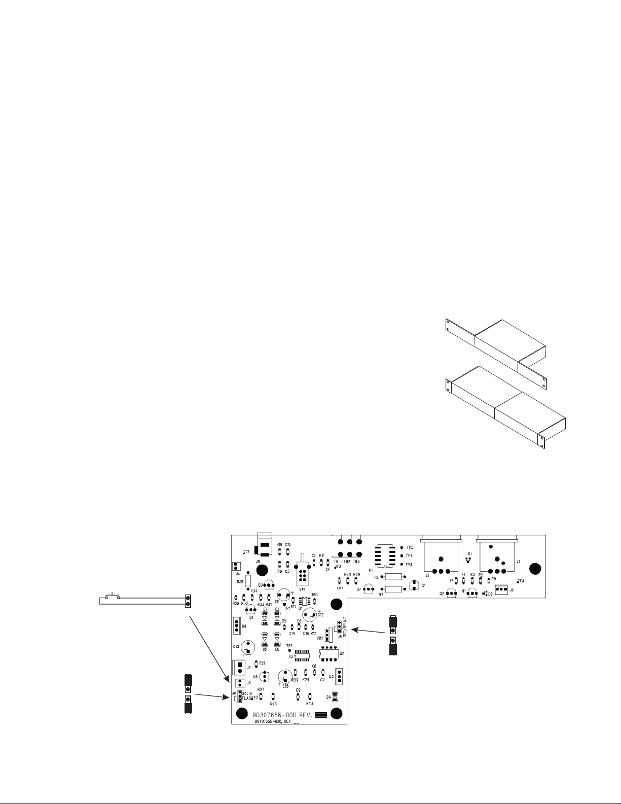
Circuit Board Configuration Jumpers
Installation
To change the jumper settings, remove the top cover.
J6: Call Light Configuration
Jumper on pins 1-2: Light flashes during call
(default-typical setting).
Jumper on pins 2-3: Light stays lit during call.
J8: Relay Configuration
Jumper on pins 1-2: Normal Open (NO) contacts closed
continuously during call (default-typical setting).
Jumper on pins 2-3: Relay contacts toggle at flash rate
during call.
External Switch
Normally, the CIA-1000 indicator light and relay are
actuated by call signals on the intercom channel. The
CIA-1000 may also be modified to actuate the light and
relay using an external, user-supplied switch. See Figure
for location of the switch connector.
1. Plug the supplied PS-L Power Supply into an AC wall
outlet and into the
12-15 VDC
power jack on the
back of the CIA-1000.
2. Set the
System Select
switch to the "in" position for
Audiocom or the "out" position for RTS TW.
3. Set the
Channel Select
switch:
• Audiocom, the position of the switch does not
matter.
• RTS TW intercom system: select either channel 1
or channel 2 as desired.
4. Connect the CIA-1000 to an intercom channel like
any other intercom station.
RMK-S Single-Unit Rack Mount Kit
for one 1/2-rack wide Audiocom
component*
Mounting
The CIA-1000 can be wall mounted using the slotted holes
in the bottom of the case.
The front-light version can be installed in an equipment
rack using optional Audiocom rack mounts.
J5: EXTERNAL SWITCH
J6: CALL LIGHT OPERATION
On continuously during call
RMK-D Dual-Unit Rack Mount Kit
for two 1/2-rack wide Audiocom
components*
Audiocom Rack Mount Kits
J8: RELA YOPERATION
Toggle during call
On continuously during call
Flash during call
602
Location of Jumpers and External Switch Connector
2
 Loading...