

Page 1
CDR-1000
OPERATING INSTRUCTIONS
SUPPLEMENT
Page 2

TABLE OF CONTENTS
1. Quick System Setup .........................SeeSection 1 in the main RE-1 Instructions
2. System Description............................................................2
3. Detailed Component Description .................................................3
4. Detailed Description of Unique CDR-1000 Features
1. Headset Port...........................................................4
2. Audio Output...........................................................4
3. Antenna Connections and Chaining .........................................4
4. RE-OneLink PC Monitoring and Control......................................5
5. Trouble Shooting Guide ........................................................6
6. Specifications ................................................................6
7. Certifications.................................................................7
8. Accessories for CDR-1000 ......................................................7
Section 1 Quick Setup
See Section 1 of main RE-1 Operating Instructions
Section 2 System Description
The CDR-1000 Wireless Microphone system
combines frequency agility and ease of use like no
other. The RE-1 transmitters and receivers operate
over a 24MHz bandwidth in the UHF portion of the
spectrum. The high quality audio circuitry and
advanced Radio Frequency (RF) signal processing
offer broadcast quality signal-to-noise and audio
clarity.
CDR-1000 Features Include:
•
Advanced ClearScan technology for selecting
clear channels and inter-modulation free groups.
•
USB Port for monitoring and controlling the
receiver from a PC.
•
Integrated antenna splitter and output jacks
•
Adjustable Balanced Line Level and fixed Mic
Level XLR output jack.
•
Headphone jack on front panel for monitoring and
setup.
•
Internal power supply with universal input.
•
960 Radio Channels, user programmable or
factory installed.
•
LCD Displays for ease of viewing.
•
Patented DSP Phase Diversity System.
•
Front Panel Power ON/OFF Switch.
•
Quadruple Tuned Ceramic Resonator front end for
superior interference rejection.
•
Triple ceramic filters in 2nd I.F for adjacent
channel rejection..
•
Double Tuned Quadrature circuit for low audio
distortion.
•
Permanent Flash Memory for frequency/system
storage.
•
Front Panel Software Control of Squelch settings
•
Double Squelch (Amplitude and Tone) system
prevents false squelch.
•
Lockout feature to prevent accidental channel
changes
•
Sound Check mode to speed walk testing and
provide tangible results.
•
SAW Filter 1st I.F for out of band rejection.
-1-
Page 3
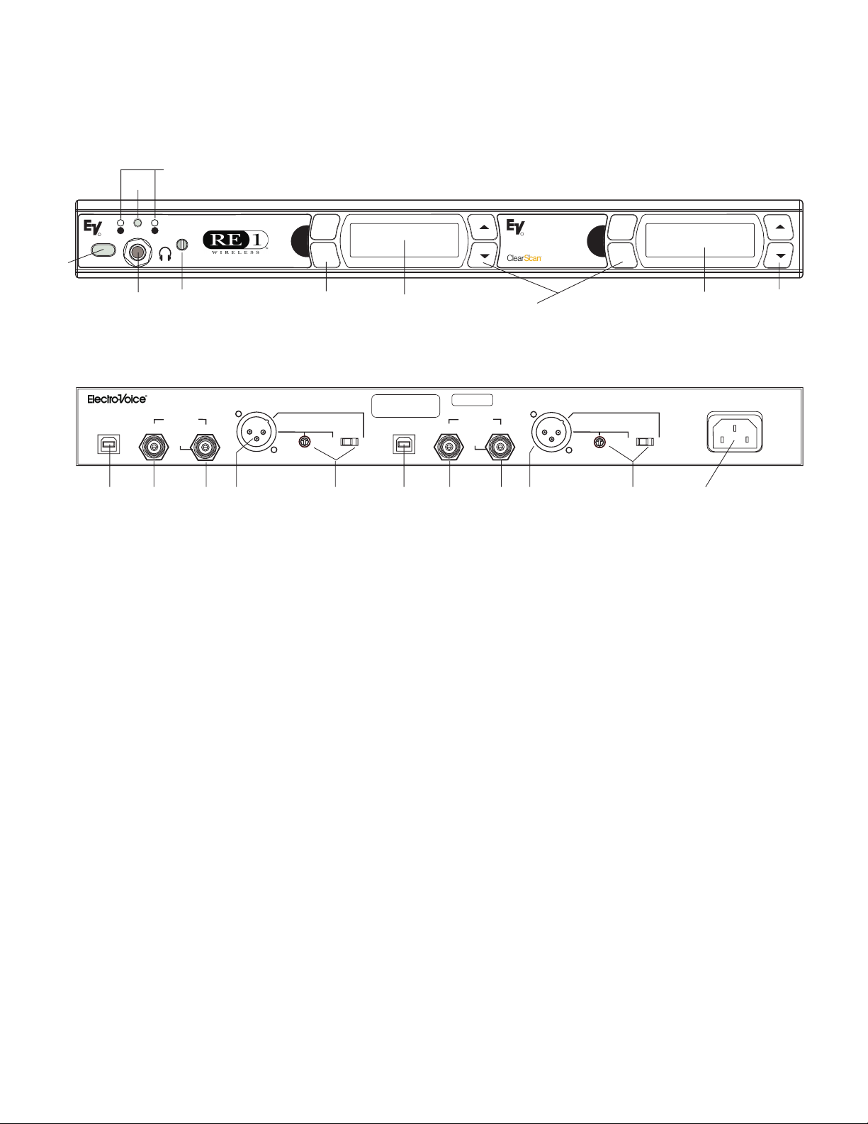
Section 3 Detailed Component Descriptions
CDR-1000 RECEIVER CONTROLS, CONNECTORS AND INDICATORS
2d
2c
1 2
R
power
1
2a
2b
menu
1
set
4
3
Figure 1
Front Panel CDR-1000 Receiver
OUT
ANTENNA
PATENTNO. 6,256,484
IN
15 Vdc
150 mA
Out
AUDIO 2
LINE
LEVEL
LINE MIC
PROGRAM 1
CDR-1000
DUAL RECEIVER
MADE IN U.S.A.
PROGRAM 2
10 9 8 6 7 10 9 8
Figure 2
Rear Panel CDR-1000 Receiver
1. Power ON/OFF
2. Headphone Monitoring
a. ¼ Inch Stereo Jack
b. Headset Volume Control
c. Receiver Select Button
d. Selected Receiver Indicator LEDs
3. Graphical Display (2)
a. Channel Display
b. Battery Strength Indicator
c. Diversity Indicator
d. RF Strength of Signal Indicator
e. Audio Level Indicator
4. Display Control Buttons (Menu/Set/Up/Down) (2 Sets)
5. Power Connector
6. Balanced Mic/Line Level XLR Audio Output (2)
7. Mic/Line Switch and Line Level Adjustment (2)
8. TNC Antenna Input Connectors (2) with 15Vdc (150mA) output on center pin
9. TNC Antenna Output Connectors (2) with factory installed “Dummy” loads (2)
10. USB Program Connector (2)
OUT
ANTENNA
15 Vdc
150 mA
Out
R
RE-1 CDR-1000
Featuring
menu
2
set
4
IN
LINE MIC
AUDIO 1
LINE
LEVEL
67
3
90-260 VAC 50-60Hz
POWER
5
4
-2-
Page 4

Section 4 Detailed Description of Unique CDR-1000 Features
Headset Operation
1. With the transmitters and receivers setup and
operating (see Sections 1 and 3 in the main RE-1
Operating Instructions), plug stereo headphones
into the 1/4inch jack on the front panel.
2. The Selected Receiver LED will indicate receiver 1
is being monitored. Press the Receiver Select
button once to change from Receiver 1 to 2.
3. Press the Receiver Select button once more and
both indicator LEDs will light. You can now listen to
both receivers.
4. Pressing the Select button once more cycles back
to Receiver 1.
Audio Output
1. The CDR-1000 is equipped with a balanced XLR
output for each receiver that can be switched
between a fixed microphone level (-10dBV) and an
adjustable line level (8mV – 0.775V RMS).
2. The CDR-1000 is equipped with a left and right
antenna output jack. These jacks can be used to
connect up to 3 CDR-1000 (6 receivers) to two
antennas without any additional equipment. DO
NOT remove “dummy” loads unless connecting to
another CDR-1000.
LPA500
R
UHF
LOGPERIODIC ANTENNA
THISEND TOWARDTRANSMITTER
CDR-1000
DUALRECEIVER
MADEIN U.S.A.
PROGRAM2
CDR-1000
DUALRECEIVER
MADEIN U.S.A.
PROGRAM2
CDR-1000
DUALRECEIVER
MADEIN U.S.A.
PROGRAM2
PATENTNO.6,256,484
ANTENNA
OUT
IN
12Vdc
150mA
Out
PATENTNO.6,256,484
ANTENNA
OUT
12Vdc
150mA
Out
PATENTNO.6,256,484
ANTENNA
OUT
12Vdc
150mA
Out
LINE MIC
LINE
AUDIO2
LEVEL
IN
LINE MIC
LINE
AUDIO2
LEVEL
IN
LINE MIC
LINE
AUDIO2
LEVEL
ANTENNA
OUT
IN
12Vdc
150mA
Out
PROGRAM1
PROGRAM1
PROGRAM1
AUDIO1
ANTENNA
OUT
IN
12Vdc
150mA
Out
AUDIO1
ANTENNA
OUT
IN
12Vdc
150mA
Out
AUDIO1
R
THISEND TOWARDTRANSMITTER
LINE MIC
LINE
LEVEL
LINE MIC
LINE
LEVEL
LINE MIC
LINE
LEVEL
LPA500
UHF
LOGPERIODIC ANTENNA
90-260VAC 50-60 Hz
POWER
90-260VAC 50-60 Hz
POWER
90-260VAC 50-60 Hz
POWER
Figure 3
Antenna Chaining
2. For microphone level operation place the Mic/Line
switch in the Mic position. The level adjustment will
have no effect on the output in the Mic setting.
3. For adjustable balanced line level operation place
the Mic/Line switch in the Line position. The level
adjustment will now affect the output.
Antenna Connections
1. The Antenna input connection includes a 15Vdc
source to power the UAA-500 UHF antenna
amplifier for long coax runs and covering large
performance areas.
NOTE: The two flexible ½ wave antennas included
with the CDR-1000 can be remote mounted. For an
additional 5dB gain use the LPA500B log periodic
directional antenna.
3. Figure 3 shows the connection diagram for 3
CDR-1000 units.
4. Up to 12 CDR-1000 units can be operated with just
two antennas with the optional APD4 antenna
distribution unit (see Figure 4).
-3-
Page 5

LPA500
R
UHF
LOGPERIODIC ANTENNA
THISEND TOWARDTRANSMITTER
LPA500
R
UHF
LOGPERIODIC ANTENNA
THISEND TOWARDTRANSMITTER
RE-OneLink PC Software
1. Software to monitor and control the CDR-1000 receivers
from a PC through the USB port is available at
www.electrovoice.com
ments are:
. Minimum system require-
CDR-1000
DUALRECEIVER
MADEIN U.S.A.
PROGRAM2
CDR-1000
DUALRECEIVER
MADEIN U.S.A.
PROGRAM2
CDR-1000
DUALRECEIVER
MADEIN U.S.A.
PROGRAM2
CDR-1000
DUALRECEIVER
MADEIN U.S.A.
PROGRAM2
CDR-1000
DUALRECEIVER
MADEIN U.S.A.
PROGRAM2
CDR-1000
DUALRECEIVER
MADEIN U.S.A.
PROGRAM2
CDR-1000
DUALRECEIVER
MADEIN U.S.A.
PROGRAM2
CDR-1000
DUALRECEIVER
MADEIN U.S.A.
PROGRAM2
CDR-1000
DUALRECEIVER
MADEIN U.S.A.
PROGRAM2
CDR-1000
DUALRECEIVER
MADEIN U.S.A.
PROGRAM2
CDR-1000
DUALRECEIVER
MADEIN U.S.A.
PROGRAM2
CDR-1000
DUALRECEIVER
MADEIN U.S.A.
PROGRAM2
OUTPUTA
1
OUT
OUT
OUT
OUT
OUT
OUT
OUT
OUT
OUT
OUT
OUT
OUT
PATENTNO.6,256,484
ANTENNA
12Vdc
150mA
Out
PATENTNO.6,256,484
ANTENNA
12Vdc
150mA
Out
PATENTNO.6,256,484
ANTENNA
12Vdc
150mA
Out
PATENTNO.6,256,484
ANTENNA
12Vdc
150mA
Out
PATENTNO.6,256,484
ANTENNA
12Vdc
150mA
Out
PATENTNO.6,256,484
ANTENNA
12Vdc
150mA
Out
PATENTNO.6,256,484
ANTENNA
12Vdc
150mA
Out
PATENTNO.6,256,484
ANTENNA
12Vdc
150mA
Out
PATENTNO.6,256,484
ANTENNA
12Vdc
150mA
Out
PATENTNO.6,256,484
ANTENNA
12Vdc
150mA
Out
PATENTNO.6,256,484
ANTENNA
12Vdc
150mA
Out
PATENTNO.6,256,484
ANTENNA
12Vdc
150mA
Out
234
IN
AUDIO2
IN
AUDIO2
IN
AUDIO2
IN
AUDIO2
IN
AUDIO2
IN
AUDIO2
IN
AUDIO2
IN
AUDIO2
IN
AUDIO2
IN
AUDIO2
IN
AUDIO2
IN
AUDIO2
LINE MIC
LINE
LEVEL
LINE MIC
LINE
LEVEL
LINE MIC
LINE
LEVEL
LINE MIC
LINE
LEVEL
LINE MIC
LINE
LEVEL
LINE MIC
LINE
LEVEL
LINE MIC
LINE
LEVEL
LINE MIC
LINE
LEVEL
LINE MIC
LINE
LEVEL
LINE MIC
LINE
LEVEL
LINE MIC
LINE
LEVEL
LINE MIC
LINE
LEVEL
INPUTA
1
PROGRAM1
PROGRAM1
PROGRAM1
PROGRAM1
PROGRAM1
PROGRAM1
PROGRAM1
PROGRAM1
PROGRAM1
PROGRAM1
PROGRAM1
PROGRAM1
POWEROUT
23
15VDC
POWER
4
15VAC/DC
ANTENNA
OUT
IN
12Vdc
150mA
Out
ANTENNA
OUT
IN
12Vdc
150mA
Out
ANTENNA
OUT
IN
12Vdc
150mA
Out
ANTENNA
OUT
12Vdc
150mA
Out
ANTENNA
OUT
12Vdc
150mA
Out
ANTENNA
OUT
12Vdc
150mA
Out
ANTENNA
OUT
IN
12Vdc
150mA
Out
ANTENNA
OUT
IN
12Vdc
150mA
Out
ANTENNA
OUT
IN
12Vdc
150mA
Out
ANTENNA
OUT
IN
12Vdc
150mA
Out
ANTENNA
OUT
IN
12Vdc
150mA
Out
ANTENNA
OUT
IN
12Vdc
150mA
Out
OUTPUTB
IN
4
32
1.3A
LINE MIC
LINE
AUDIO1
LEVEL
LINE MIC
LINE
AUDIO1
LEVEL
LINE MIC
LINE
AUDIO1
LEVEL
IN
IN
IN
LINE MIC
LINE
AUDIO1
LEVEL
LINE MIC
LINE
AUDIO1
LEVEL
LINE MIC
LINE
AUDIO1
LEVEL
LINE MIC
LINE
AUDIO1
LEVEL
LINE MIC
LINE
AUDIO1
LEVEL
LINE MIC
LINE
AUDIO1
LEVEL
LINE MIC
LINE
AUDIO1
LEVEL
LINE MIC
LINE
AUDIO1
LEVEL
LINE MIC
LINE
AUDIO1
LEVEL
1
90-260VAC 50-60 Hz
90-260VAC 50-60 Hz
90-260VAC 50-60 Hz
90-260VAC 50-60 Hz
90-260VAC 50-60 Hz
90-260VAC 50-60 Hz
90-260VAC 50-60 Hz
90-260VAC 50-60 Hz
90-260VAC 50-60 Hz
90-260VAC 50-60 Hz
90-260VAC 50-60 Hz
90-260VAC 50-60 Hz
INPUTB
Windows 2000
512 Mbytes of RAM
POWER
POWER
POWER
POWER
POWER
POWER
POWER
POWER
POWER
POWER
POWER
POWER
One USB port
USB Hubs for controlling multiple receivers
CD-ROM Drive
2 Mbytes of hard drive memory
Figure 4
Antenna Chain with APD4
.
-4-
Page 6

Section 5 Trouble Shooting Guide
Problem Possible Causes Solutions
Receiver audio output cable is
No (or low) Audio with good RF
signal and Audio indicatiors on
receiver display
disconnected or connected to
the wrong receiver.
Audio Output in Mic position or
line level adjustment low
Low RF Signal
For more trouble shooting information see Section 6 in the main Operating Manual.
antennas connected to output
instead of input jack.
Repair, replace cable or connect
cable to the correct receiver.
Adjust audio output (See Audio
Output section)
Connect antennas to the input
jack.
Section 6 CDR-1000 Receiver Specifications
Receiver Type .......................................................Synthesized PLL
Frequency Range (RF) ............................................ABand 680 - 704 MHz
B Band 722 - 746 MHz
D Band 798 - 822 MHz
E Band 841 - 865 MHz
H Band 740 - 752 MHz
T Band 794 - 806 MHz
Number of Channels.............................................>900possible channels
Programmable in 25 kHz steps
Modulation ...............................................................+/-40kHz
Diversity ...............................................DSPPosi-Phase™ True Diversity
RF Sensitivity ................................................<0.8mVfor12dBSINAD
Image Rejection..............................................................>60dB
Squelch .....................................................Tone Code plus Amplitude
Ultimate Quieting ...........................................................>100dB
FCC Certification................................................Approved under Part 15
Power Requirements ...............................................15VAC,750mA max
Antenna Output DC Power (center pin) .....................................15VDC, 150mA
Operating Temperature ........................................-7ºto49ºC(20º to 120º F)
Dimensions: ............................................1.72 in. H x 16 in. W x 10.25 in. D
43.7mm H x 408 mm W x 261.4 mm D
Audio Parameters
Frequency Response ................................................30–15kHz +/- 2dB
Fixed Mic Level Balanced Output ..........................-10dBV(max@40kHzdeviation)
Line Level Balanced Output .................................adjustable 8 mV to 0.755V RMS
Distortion..............................................<0.5% (ref 1kHz, 40kHz deviation)
Signal-to-Noise Ratio .........................................................>110dB
Dynamic Range .............................................................>100dB
-5-
Page 7

Section 7 Certification
CERTIFICATIONS
(Depending on frequency selected and country of operation)
CDR-1000 Receiver, CSH-1000 Transmitter, CSB-1000 Transmitter
Certified to ETSI EN 300 422-2 and ETSI EN 301 489-3, Conforms to European Union directives, eligible to bear CE
marking as per the R&TTE Directive. Certified for use in Canada under RSS 123 Issue 1.
The CDR-1000 is authorized under United States Federal Communications Commission, Part 15.
The CSH-1000 and CSB-1000 are Type Accepted under United States Federal Communications Commission, Part
74.
Licensing of this equipment is the user’s responsibility and is determined by the user’s classification, the
user’s application, and frequency selected. The user should contact the appropriate telecommunications
authority for any desired clarification. Any changes or modifications made to the aforementioned
equipment, by the user, could void the user’s authority to operate the equipment.
Section 8 Accessories
ACCESSORIES AND PARTS for CDR-1000
MODEL # ORDER #
UHF Wideband Antenna Amplifier (520 – 806 MHz) UAA-500 7186400
½ WAVE FLEXIBLE Rx ANTENNA (680-860 MHz) FA-1 860031
-6-
Page 8

TELEX COMMUNICATIONS, INC.•12000 Portland Ave. South, Burnsville, MN 55337.
PN AUG 2002 Made in U.S.A.
 Loading...