

Page 1

Care and Feeding of Telex Radio Dispatch Systems
C-6200 Setup
Entering the Setup Mode
Setup of the C-6200 is almost entirely done using a web browser. The first step required during setup
is to assign the Ethernet and Mask addresses to the C-6200. This is done through the front panel. To
enter the front panel setup mode, press and hold MUTE-F16-GRP.
Setting the System Clock
Pressing PROG1 from the top-level setup menu will open the screen to set the internal Real Time
Clock. PROG1 selects the Edit option that allows setting of the actual minutes and hours. PROG2
sets AM or PM., PROG3 selects 12 or 24-hour mode, PROG4 returns to the previous setup screen.
The clock can also be directly setup by pressing MUTE-F16-C1. This key sequence bypasses the
PIN number and the main setup screen.
Setting the PIN number
The Pin number is used to prevent unauthorized modification of operation parameters. When a PIN
number is set, the C-6200 will prompt for it before allowing entry into the setup mode. The webbased setup for the C-6200 also has provision for a user password; it is the same four-digit value as
the PIN number entered from this menu option. Selecting PROG3 from the main menu will cause
the C-6200 to prompt for the new PIN number twice. If both are entered identically, the new PIN
number will take affect.
Phase 4 Design, Inc.
Dave Grant / dgrant@hostnw.net
425.402.7308
11/5/2010 Page 1 of 18
Page 2
Care and Feeding of Telex Radio Dispatch Systems
C-6200 Setup
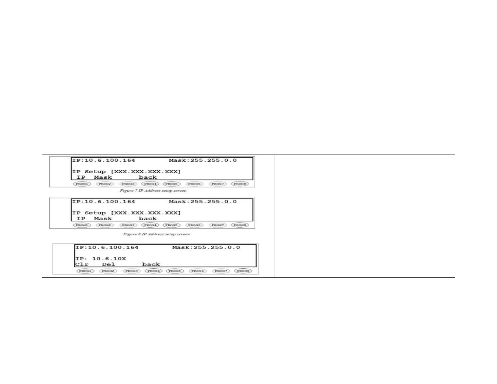
Setting the basic IP information
As was mentioned before, all other parameters are setup by using a browser such as Netscape or
Internet Explorer. Before connecting to the console with the browser, an IP address and Mask that is
compatible with the users existing network must be set. Figure 7 shows the screen selected when
PROG2 is pressed from the main setup screen. See your network administrator to determine the
proper values. The following keys are used to enter the IP dotted quad once PROG1 or PROG2 is
pressed.
DTMF 0-9: The DTMF digits allow entry of the specific
numbers .
DTMF A: DTMF digit A is the decimal point used in
dotted quad PROG4: The “back” key is pressed when the
dotted quad has been entered.
PROG1: The “Clr” function clears the current entered
value and starts over.
PROG2: The “Del” function deletes the last entered
number.
Once these values have been set, the unit must be
reset for them to take affect. It is now possible to
connect to the C-6200 with a computer and web browser.
Phase 4 Design, Inc.
Dave Grant / dgrant@hostnw.net
425.402.7308
11/5/2010 Page 2 of 18
Page 3

Care and Feeding of Telex Radio Dispatch Systems
C-6200 Backplane connections
C-6200 Setup
Battery backup:
The Auxiliary power input (3-Pin terminal block) is a diode-protected +12V input used for battery
backup. Pin (E) is also connected to the chassis allowing for positive grounding of the unit.
Phase 4 Design, Inc.
Dave Grant / dgrant@hostnw.net
425.402.7308
11/5/2010 Page 3 of 18
Page 4

Care and Feeding of Telex Radio Dispatch Systems
C-6200 Setup
Auxiliary Speaker:
The DB9 SPKR/FS connector has Selected, Unselected and Crosspatch audio outputs for driving
external 8-ohm speakers.
Footswitch:
The DB9 SPKR/FS connector provides footswitch and ground connections. This input acts as a
console PTT when it is shorted to ground.
Auxiliary Audio Input:
The DB25 AUX connector provides AUX Audio Input and PTT. Pulling PTT to ground activates the
Audio Input line for transmitting. This input is a high impedance capacitance coupled input.
Record Output
The DB25 AUX connector has Selected, Unselected and Crosspatch audio via 600ohm transformer
output for connection to a voice-logging recorder.
Phase 4 Design, Inc.
Dave Grant / dgrant@hostnw.net
425.402.7308
11/5/2010 Page 4 of 18
Page 5

Care and Feeding of Telex Radio Dispatch Systems
C-6200 Setup
Auxiliary Relay Output:
The DB25 AUX connector provides connection to the AUX relays, depending on the setting of the
AUX button in the tech mode, this output is a relay closure that can be used for whatever purpose is
required.
Auxiliary DB25 Connector:
Phase 4 Design, Inc.
Dave Grant / dgrant@hostnw.net
425.402.7308
11/5/2010 Page 5 of 18
Page 6

Care and Feeding of Telex Radio Dispatch Systems
C-6200 Setup
6200TCRD - Line Ports 1-9:
The C-6200 can accommodate up to 18-lines, in multiples of two. The nine-line connectors are on
the rear of the unit and are standard DB25 connectors for TCRD and RJ-12 for PCRD. The pin-outs
of the connectors appear below.
Phase 4 Design, Inc.
Dave Grant / dgrant@hostnw.net
425.402.7308
11/5/2010 Page 6 of 18
Page 7

Care and Feeding of Telex Radio Dispatch Systems
C-6200 Setup
Cross-mute
When a parallel console operator keys a microphone in the same room, the cross-mute function
mutes the receive audio path of the other parallel consoles. This prevents any unwanted audio loops
that would occur causing a loud squeal on the paralleled speakers. Feedback may be avoided by
muting the receive audio of the line card which is in parallel with a transmitting line card. This may
be accomplished by connecting pins 12 (line 1) or 6 (line 2) of each of the consoles to be crossmuted. Pin 21 must be connected to provide a common ground and place J15 (line 1) or J14 (line 2)
into the “A” position. Note: The intercom function will not work between cross-muted consoles.
Phase 4 Design, Inc.
Dave Grant / dgrant@hostnw.net
425.402.7308
11/5/2010 Page 7 of 18
Page 8
Care and Feeding of Telex Radio Dispatch Systems
C-6200 Setup
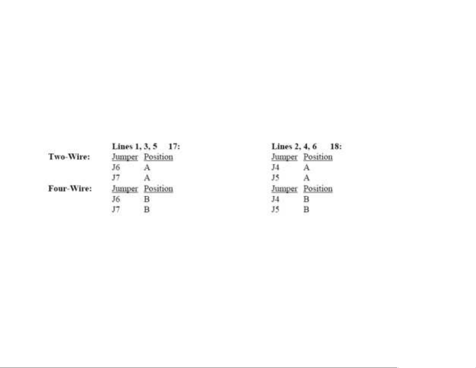
Two-Wire/Four-Wire Mode
Each Line Card comes standard with a jumper selectable two or four-wire option. Note: The Line
Cards are shipped in the four-wire mode. Two-wire mode is accomplished by the following jumper
positions:
The RX pairs are now on pins 11 and 22 (line 1), 5 and 16 (line 2) on the connector. The TX pairs
are on pins 10 and 23 (line 1), 4 and 17 (line 2) of the connector. Once transmit and receive paths are
separated, the impedance of each side must be set.
Phase 4 Design, Inc.
Dave Grant / dgrant@hostnw.net
425.402.7308
11/5/2010 Page 8 of 18
Page 9

Care and Feeding of Telex Radio Dispatch Systems
C-6200 Setup
RX Side Settings
The RX side is jumper selectable for 600 or 10k ohm impedance. In 4 Wire mode, If only one
console is on the line (no parallel consoles) then place J10 (Line 1) or J8 (Line 2) in the A position
for a 600 Ohm line impedance. If more than one console is on one line, then place J10 (Line 1) or J8
(Line 2) on ONE console in the A position and all other consoles in the B position. Each console
added to the system will result in line loss. The following chart gives an indication as to how much
loss can be expected. The first console in the system is set for an impedance of 600 ohms out
(approximately). Each console added to the system thereafter is set for an impedance of 10k ohms.
As the chart indicates on the following page, the more consoles bridged on the line, the lower the
line impedance and the greater the loss in audio level.
Level adjustment can be made to the receive audio by entering the tech mode on a per line basis.
TX Side Settings
Phase 4 Design, Inc.
Dave Grant / dgrant@hostnw.net
425.402.7308
11/5/2010 Page 9 of 18
Page 10

Care and Feeding of Telex Radio Dispatch Systems
C-6200 Setup
The C-6200 TX output circuitry has a DPDT relay that is used to connect and disconnect the TX
output transformer from the TX line based on PTT status. This allows a very large number of
consoles to be attached to the line in parallel, because only the transmitting unit will be directly
connected to the line. When not transmitting, the DPDT relay is connected to 600 ohms or open
circuit depending on the number of console connected in parallel to the line. If only one console is
attached, this unit should have J9 (Line 1) or J3 (Line 2) in the “A” position. This makes it the
effective master and terminates the line with 600 ohms. If there are more than one console connected
in parallel, one console should be designated as the master by placing J9 (Line 1) or J3 (Line 2) in
the “A” position and the remaining consoles should be designated as a slave and should have J9
(Line 1) or J3 (Line 2) placed in the “B” position. In this manner, the impedance looking back into
the parallel configuration of consoles is still 600 ohms.
Phase 4 Design, Inc.
Dave Grant / dgrant@hostnw.net
425.402.7308
11/5/2010 Page 10 of 18
Page 11
Care and Feeding of Telex Radio Dispatch Systems
C-6200 Setup
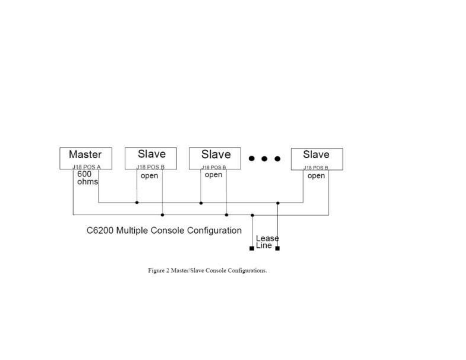
Figure 2 shows a basic configuration, the C-6200 could also be the master in this configuration.
NOTE: If any of the consoles connected in parallel are not C-6200’s, then all the C6200’s should be
configured as slaves. Additionally, J18 (Line 1) or J17 (Line 2) should be used as a TX line
impedance correction if there are consoles other than the C-6200 connected in parallel. J18 (Line 1)
or J17 (Line 2) position “B” adds another 600ohms to the output TX line. J18 (Line 1) or J17 (Line
2) Position “A” is straight through.
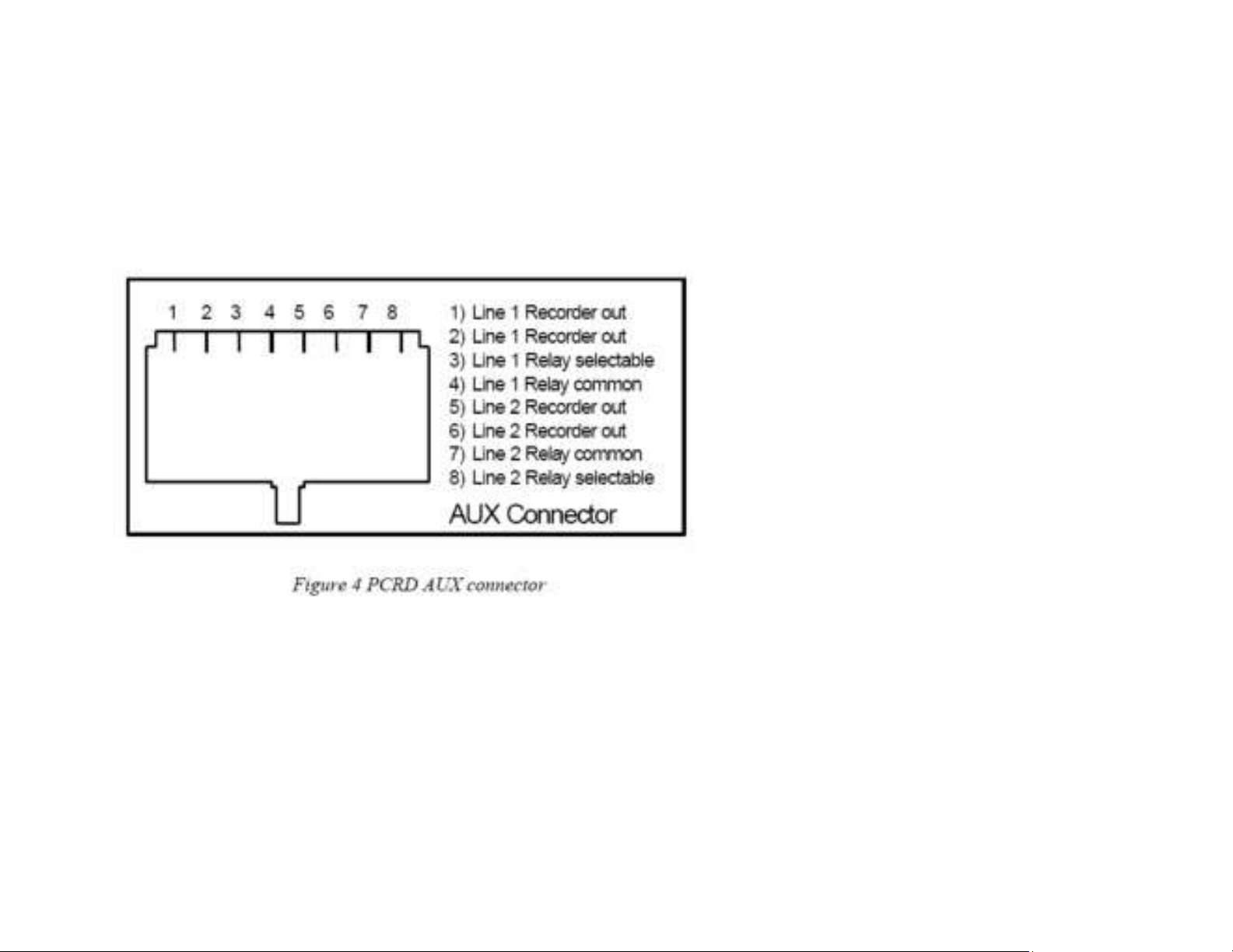
Aux Connector:
Phase 4 Design, Inc.
Dave Grant / dgrant@hostnw.net
425.402.7308
11/5/2010 Page 11 of 18
Page 12
Care and Feeding of Telex Radio Dispatch Systems
C-6200 Setup
A RJ-45 connector is provided for auxiliary functions per line, recorder out and relay
closure. See Figure 4
Phase 4 Design, Inc.
Dave Grant / dgrant@hostnw.net
425.402.7308
11/5/2010 Page 12 of 18
Page 13

Care and Feeding of Telex Radio Dispatch Systems
C-6200 Setup
Transmit Path:
The transmit path begins at the microphone of your choice and ends with the transmit line card jack.
Microphone adjustments
There are three microphone inputs to the C-6200. A gooseneck connector is provided for on the front
of the console and is default with the front panel PTT. Two inputs are accessible from the rear of the
unit. One is a four-wire connector and the other is a six-wire connector. The four-wire connector will
accept either a handset or headset. The six-wire connector will accept desk microphone. All
connectors may be used at the same time. Transmit audio from the six-wire connector is blocked
only when the PTT of the four-wire connector is active. The gooseneck, handset/headset and the
desk microphone inputs go through dedicated preamplifier stages and CODEC’s are then connected
to the DSP by the PTT source. In setting the microphone levels the goal is to adjust the preamps so
that nominal voice levels through both microphones (if two are being used simultaneously) are of
equal level at the input of the CODEC’s . The following procedures will guide you through the
tuning process:
Phase 4 Design, Inc.
Dave Grant / dgrant@hostnw.net
425.402.7308
11/5/2010 Page 13 of 18
Page 14

Care and Feeding of Telex Radio Dispatch Systems
C-6200 Setup
Adjusting the handset/headset microphone levels
Make a vocal tone into the handset and adjust RV4 for approximately 2V Peak to peak at TP11. The
sidetone level can be adjusted from within the tech mode. Speak into the handset and listen to the
earpiece. You should hear a portion of your voice being routed back to the earpiece.
Adjusting the desk microphone level
Make a vocal tone into the desk microphone at the distance you expect the operator to be positioned
and adjust R188 on the Backplane PCB for 2Vp-p at TP1. The output of the compressor circuit U31
can be adjusted by RV3 for approximately 2V Peak to peak at TP5.
Adjusting the gooseneck microphone level
Make a vocal tone into the gooseneck microphone at the distance you expect the operator to be
positioned and adjust R191 on the Backplane PCB for 2 Vp-p at TP3. The output of the compressor
circuit U30 can be adjusted by RV1 for approximately 2V Peak to peak at TP4.
Phase 4 Design, Inc.
Dave Grant / dgrant@hostnw.net
425.402.7308
11/5/2010 Page 14 of 18
Page 15

Care and Feeding of Telex Radio Dispatch Systems
C-6200 Setup
Line Card Transmit Path Adjustment
Once the microphone audio has been digitized, the DSP will first route it through a 2175Hz notch
filter to remove 2175Hz components from the voice. This is done to make sure that no component of
the microphone audio will interfere with the 2175Hz hold tone. At the output of the notch filter the
microphone audio is summed together with the last of the signaling components. From this point the
total transmit audio mix is sent to the DAC and then to the individual output drivers of the Line
Cards.
Transmit Level Adjustment
The transmit level is setup using software potentiometers to adjust the levels of the transmit audio.
Calibration of the TX lines will vary depending on system variables as well as the number of
consoles found in parallel on the line. The tech can use an alert tone set to continuous as a test tone
of given amplitude for this alignment.
Transmit Monitor
The four-wire transmit monitor provides a portion of the transmit audio to the receive path. This
allows the console operator to listen to the transmissions of parallel consoles. To set this level have a
parallel console operator intercom on the line to be set. Adjust R95 (line 1) and R87 (line 2) until the
level is comfortable in the handset/headset earpiece or the speaker.
Phase 4 Design, Inc.
Dave Grant / dgrant@hostnw.net
425.402.7308
11/5/2010 Page 15 of 18
Page 16

Care and Feeding of Telex Radio Dispatch Systems
C-6200 Setup
Receive Path
The Receive path begins at the input to the line card and ends with a speaker or earpiece. There are
very few adjustment that need to be made to the receive path. The DSP will detect and compensate
for most variations in audio levels.
7.3.1 Line Activity Monitor (LAM) / Squelch Control
The green LED under each Release Button will blink when activity is on the line. The default level
for the C-6200 console to trigger the LAM is -10dBm. The trigger point can be changed within the
tech mode. Note that the LAM can be used as a squelch circuit. The Select and Unselect audio paths
may be independently controlled by the LAM. Both options can be configured in tech mode.
Master Recorder Outputs
Three 600 ohm balanced notched audio outputs are provided for the use with an external recorder.
Select, Unselect and Crosspatch outputs are provided; the Selects actual audio sent is the sum of
Microphone and selected receive audio.
Phase 4 Design, Inc.
Dave Grant / dgrant@hostnw.net
425.402.7308
11/5/2010 Page 16 of 18
Page 17

Care and Feeding of Telex Radio Dispatch Systems
C-6200 Setup
Auxiliary Speaker Outputs
The auxiliary speaker outputs can be used to drive additional external speakers, Select, Unselect and
Crosspatch outputs are provided.
Earth Ground
While Telex-Vega recommends that the unit be tied to earth ground though the AUX power
connector on the back of the unit. It is imperative that chassis ground to tied to some fixed reference
for proper operation of the unit. The line filtering is dependent on a solid ground to function
correctly.
Phase 4 Design, Inc.
Dave Grant / dgrant@hostnw.net
425.402.7308
11/5/2010 Page 17 of 18
Page 18

Care and Feeding of Telex Radio Dispatch Systems
C-6200 Setup
Line Card Installation
Installing and removing line cards can be completed in the field by qualified personnel. The steps for
this process are listed below.
1) Remove power from the console.
2) Remove the flathead screws holding the top of the case to the bottom chassis. A Phillips
screwdriver will be required. Also remove the screws holding the rear cover.
3) The case top should be removed in a vertical direction, once the case top is clear of the bottom, set
the top on its sides to the right of the case. Sufficient cable length is available for this without
disconnection of cables.
4) Remove the hole cover for the line card position you wish to install
5) Insert the card into the slot making sure that that the DB25 jack is flush with the back of the C-
6200.
6) Place the top back on, first making sure that all connections of the cable assy. are connected.
7) Replace all screws removed in the first step.
An exploded view of the case can be found with the schematics and parts placement drawings.
Phase 4 Design, Inc.
Dave Grant / dgrant@hostnw.net
425.402.7308
11/5/2010 Page 18 of 18
 Loading...