

Page 1

C-2000 and C-2000HS
Technical Manual
F.01U.174.927 Rev 03 09/2011
Page 2

PROPRIETARY NOTICE
CONTACT INFORMATION
The product information and design disclosed herein were
originated by and are the property of Bosch Security Systems, Inc.
Bosch reserves all patent, proprietary design, manufacturing,
reproduction, use and sales rights thereto, and to any article
disclosed therein, except to the extent rights are expressly granted
to others.
COPYRIGHT NOTICE
Copyright 2011 by Bosch Security Systems, Inc. All rights
reserved. Reproduction, in whole or in part, without prior written
permission from Bosch is prohibited.
*All other trademarks are property of their respective owners.
**MOTOROLA and the Stylized M logo are registered in the U.S.
Patent and Trademark Office.
WARRANTY NOTICE (LIMITED)
For warranty and service information, refer to www.telex.com/
warranty.
FACTORY SERVICE CENTER
Factory Service Center
Bosch Security Systems, Inc.
Radio Dispatch Products
8601 East Cornhusker Highway
Lincoln, Nebraska, 68507
Sales:
Phone ...........................................................(800) 752-7560
Fax................................................................(402) 467-3279
E-mail................................... TelexDispatch@us.bosch.com
Customer Service Repair:
E-mail...................................... repair.lincoln@us.bosch.com
Phone.............................................................(800) 553-5992
Technical Support:
Knowledge Database ..http://knowledge.boschsecurity.com/
Live Chat ..................... www.telex.com/us/dispatch/support
E-mail ................ TelexDispatchtechsupport@us.bosch.com
Web ..........................................................................www.telex.com
CLAIMS
No liability will be accepted for damages directly or indirectly
arising from the use of our materials or from any other causes. Our
liability shall be expressly limited to replacement or repair of
defective materials.
WARNING
This is a Class A product. In a domestic environment this product
may cause radio interference in which case the user may be
required to take adequate measures.
Do not open the unit. No user serviceable parts are contained
within. Bosch cannot be responsible for damage. If the unit is
opened, the warranty can be voided.
Page 3

Table
of
Contents
INTRODUCTION......................................................................................................................... 5
Overview.................................................................................................................................................. 5
Features ....................................................................................................................................................6
C-2000HS Features ............................................................................................................................................. 6
C-2000 Features .................................................................................................................................................. 6
Display Character Description ............................................................................................................................ 6
Hardware Overview .................................................................................................................................7
C-2000 Console ................................................................................................................................................... 7
Line Interface ...................................................................................................................................................... 7
Controls and Indicators ............................................................................................................................7
Front Panel ...............................................................................................................................................7
Common Controls and Indicators ............................................................................................................8
Volume Control ................................................................................................................................................... 8
Panel PTT Push button ........................................................................................................................................ 8
DTMF Keypad .................................................................................................................................................... 8
Dual Seven-Segment Display .............................................................................................................................. 8
Function Buttons Up-Down ................................................................................................................................ 8
Transmit LED ...................................................................................................................................................... 8
Monitor ................................................................................................................................................................ 8
Intercom (IC) ....................................................................................................................................................... 8
Rear Panel Connections ...........................................................................................................................9
Rear Panel Ports .................................................................................................................................................. 9
Power Jack ....................................................................................................................................................... 9
Line Port ........................................................................................................................................................... 9
Auxiliary Audio Input ...................................................................................................................................... 9
Auxiliary Speaker ............................................................................................................................................ 9
Battery Backup ............................................................................................................................................... 10
Earth Ground .................................................................................................................................................. 10
Data Port ........................................................................................................................................................ 10
Specifications .........................................................................................................................................10
INSTALLATION 11
Line Setup and Description ....................................................................................................................11
Introduction ....................................................................................................................................................... 11
Feature Description ........................................................................................................................................... 12
Crossmute ....................................................................................................................................................... 12
Supervisor Function ....................................................................................................................................... 12
Relay Contact Closure For Local Control ...................................................................................................... 13
2-Wire/4-Wire Mode ...................................................................................................................................... 13
RX Side Settings ............................................................................................................................................... 13
TX Side Settings ............................................................................................................................................ 14
Page 4

Transmit Monitor ........................................................................................................................................... 14
Level Adjustments ............................................................................................................................................. 14
Transmit Side Adjustments ............................................................................................................................14
Reference Description.................................................................................................................................... 14
Mic Input level Adjustment ............................................................................................................................... 15
TX Output Level Adjust ................................................................................................................................. 15
Transmit Monitor Setup ................................................................................................................................. 15
RX Level Adjustment ....................................................................................................................................15
SETUP .........................................................................................................................................17
Setup Mode ............................................................................................................................................17
Entering Setup Mode ......................................................................................................................................... 17
Exiting Setup Mode ...........................................................................................................................................18
Maneuvering Through Setup Mode .................................................................................................................. 18
Setup Mode Control Keys .............................................................................................................................. 18
Setup Mode Philosophy ................................................................................................................................. 18
Setup Mode Navigation Overview ................................................................................................................. 20
Setup State 0 PIN Number Entry/Idle ............................................................................................................21
Setup State 1 PIN Number Change ................................................................................................................21
Setup State 2 Guard/Hold Tone Frequency ................................................................................................... 21
Setup State 3 Guard Tone Level .................................................................................................................... 22
Setup State 4 Guard Tone Duration ...............................................................................................................22
Setup State 5 Hold Tone Level ......................................................................................................................22
Setup State 6 Hold Tone PTT Hang Time ..................................................................................................... 23
Setup State 7 Function Tone Level ................................................................................................................ 23
Setup State 8 Function Tone Duration ........................................................................................................... 23
Setup State 9 Single/Dual Function Tone Mode ............................................................................................ 24
Setup State 10 Function Tone Frequency ...................................................................................................... 24
Setup State 11 Monitor Frequency Select ...................................................................................................... 26
Setup State 12 DTMF Keypad Enable/Disable/Enable (without PTT) ......................................................... 26
Setup State 13 DTMF Tone Level .................................................................................................................26
Setup State 14 DTMF Hang Timer ................................................................................................................27
Setup State 15 MIC AGC Enable/Disable ..................................................................................................... 27
Setup State 16 RX AGC Enable/Disable ....................................................................................................... 27
Setup State 17 Main Speaker with Handset Enable/Disable ..........................................................................28
Setup State 18 SF Mode Enable/Disable (Special Software Option) ............................................................ 28
Setup State 19 Aux Speaker Enable/Disable .................................................................................................28
Setup State 20 Function Tone Enable/Disable ...............................................................................................29
Setup State 21 Crossmute Output Enable/Disable .........................................................................................29
Setup State 22 Min Speaker Level Enable/Disable ........................................................................................29
Setup State 23 Handset Mic Level ................................................................................................................. 30
Setup State 24 Deskmic Level .......................................................................................................................30
Setup State 25 Aux Input Port Level .............................................................................................................. 30
Setup State 26 Panel Microphone Input Level ............................................................................................... 31
Setup State 27 RX Line Jack Level ................................................................................................................ 31
Setup State 28 TX Line Jack Level ................................................................................................................ 31
Setup State 29 Clone Mode ............................................................................................................................ 32
Clone Mode Overview ................................................................................................................................... 33
Setup State 30 Full Duplex Mode Enable/Disable .........................................................................................33
Setup State 31 Handset Enable/Disable .........................................................................................................33
Setup State 32 Auto-Monitor Enable/Disable ................................................................................................34
Setup State 33 Tone/Local Mode ...................................................................................................................34
Page 5

Setup State 34 Squelch Level ......................................................................................................................... 34
Setup State 35 Squelch Enable/Disable ......................................................................................................... 35
Setup State 36 Squelch Hang Time ................................................................................................................ 35
Setup State 37 TX Monitor Enable/Disable ................................................................................................... 35
Setup State 38 Tone Detector Threshold ....................................................................................................... 36
Setup State 39 Headset Enable/Disable ......................................................................................................... 36
Setup State 40 TX Delay Period .................................................................................................................... 37
Setup State 41 Desk Microphone Enable/Disable ......................................................................................... 37
Setup State 42 Ring Type Select (Special Software Option) ......................................................................... 37
Setup State 43 EMSTEL Enable/Disable (Special Software Option) ............................................................ 38
Setup State 44 DTMF Sequence Entry .......................................................................................................... 38
Setup State 45 Ring Duration (Special Software Option) .............................................................................. 39
Setup State 46 DTMF Sequence Enable/Disable ........................................................................................... 40
Setup State 47 Function Tone Launch Delay ................................................................................................. 40
Setup State 48 Parallel Update Enable/Disable ............................................................................................. 40
Setup State 49 Alert Tone Enable/Disable ..................................................................................................... 41
Setup State 50 Alignment Tone On/Off 41
C-6200 Worksheet .................................................................................................................................42
Page 6

Page 7

CHAPTER 1
Introduction
Overview
The C-2000 is a full featured single-channel, multi-format, and self-contained desktop radio control console. Its sleek and
modern look compliments any surrounding.
The C-2000 is a DSP (Digital Signal Processor) based design, allowing easy field programmability using the
DTMF (Dual Tone Multi-Frequency) keypad on the front of the console. Unlike other manufacturers’ equipment, no
additional software is required to program the C-2000 console. Modifications and enhancements can generally be made
through software changes only. If the user determines they require a special feature enhancement, please contact the Radio
Dispatch Sales Department for cost and feasibility.
Initial line level adjustments are made via potentiometers allowing for ease of installation. Should additional adjustments be
required, they can be made in the programming mode. AGC (Automatic Gain Control) on the receive and microphone audio
paths help stabilize line level adjustments.
The C-2000’s modular design offers control of one (1) base station, along with selection of 99 frequencies. The line interface
offers crossmute capability and squelch control feature eliminating the unwanted noise that is generally associated when
monitoring a line.
The C-2000 accommodates a desk microphone along with a handset (or headset) as indicated on the side of the C-2000
console. In addition to the external microphone options, a built in panel microphone is available by pressing the
PTT (Push-To-Talk) on the front of the panel. When a PTT occurs from any of the three (3) microphones, the others will mute
so as not to pick-up unnecessary ambient noise during transmission. When the handset is enabled and taken off hook, the
receive audio is transferred to the earpiece.
The console is normally used in conjunction with a matching Radio Dispatch 223 Series (or equivalent) tone-remote panel
located at the base station. The console is compatible with Motorola
control systems employing the industry-standard sequential tone-control format.
The console is connected to the mating panels by means of shielded voice-grade or better leased or private lines (including
microwave circuits). Metallic or DC continuity is not required.
1
, MA/Com Net Ericsson/GE1, and other tone-remote
1. See “Copyright Notice” on page 2.
Bosch Security Systems, Inc. Technical Manual F.01U.174.927 Rev 03
Page 8

6 Introduction C-2000 and C-2000HS Technical Manual
Features
C-2000HS Features
The C-2000HS is shipped from the factory in the following state:
• 4-wire mode
• Full-duplex
• TX monitor enabled
• F3–F16 disabled
• 600 Ohm TX output impedance
• 600 Ohm RX input impedance
C-2000 Features
The C-2000 is shipped from the factory in the following state:
• 4-wire mode
• Full-duplex
• TX monitor enabled
• F3–F16 Disabled
• 600 Ohm TX output impedance
• 600 Ohm RX input impedance
• Handset disabled
• Desk microphone enabled.
Display Character Description
CC (Clone Complete) - Cloning is successful.
CL (Clone Mode) - Clone mode is entered.
CD (Crossmute) - Another parallel console is active and pull crossmute low.
CP (Correct PIN) - The PIN number is correctly entered.
EE (Error) - An error occurred, seen in clone mode if cloning fails.
EP (Enter Pin) - A PIN number needs to be entered to access setup mode.
FD (Function Duration) - Function duration programming mode is entered.
FF (Function Frequency) - Function frequency programming mode is entered.
IP (Incorrect PIN) - An incorrect PIN number was entered.
OC (Option Changed) - The option selected is changed.
PC (PIN Changed) - The PIN was successfully changed.
SS (Settings Saved) - The current settings are permanently saved.
SU (Supervisor) - The supervisor pin is activated by a parallel console.
Bosch Security Systems, Inc. Technical Manual F.01U.174.927 Rev 03
Page 9

C-2000 and C-2000HS Technical Manual Introduction 7
Hardware Overview
The C-2000 is a single-line, multi-mode console designed specifically for small- to medium-level systems. All functions are
housed in a single small modern looking console.
C-2000 Console
The C-2000 console consists of two (2) sub-assemblies; the main processing board and keypad/display board that are enclosed
in a single case.
Line Interface
The Line interface is an 8-pin RJ-45 connector, using either the standard tone control format compatible with
Motorola and M/A ComNet Ericsson/GE or Local Control relay closure. The line interface may be hardware configured for
either a 2-wire or 4-wire operation and may be factory modified to accommodate non-industry standard tone control formats,
if desired. This is usually a software only change.
Controls and Indicators
FIGURE 1. Front Panel
Front Panel
The Front Panel, shown in Figure 1, contains the user I/O. It features volume and function tone selection, intercom and
monitor functions, DTMF keypad, panel PTT and microphone, as well as the dual seven-segment display.
Bosch Security Systems, Inc. Technical Manual F.01U.174.927 Rev 03
Page 10

8 Introduction C-2000 and C-2000HS Technical Manual
Common Controls and Indicators
Vol u me Co n tro l
The Volume Control is used to adjust the receive audio speaker and handset level of the audio present on the receive inputs of
the line interface. A minimum volume level can be configured in the setup mode so the console operator can not turn the
volume to zero (0). When adjusting the level up or down, the display shows the selected level on a relative scale with zero (0)
being off and 25 being full volume.
Panel PTT Push button
The Panel PTT Push button when pressed, audio from the panel microphone, or desk microphone if enabled, is sent on the
TX line interface.
DTMF Keypad
The DTMF keypad is used for transmitting DTMF. The DTMF keypad is also used in the setup mode. It can also be disabled
in user mode.
Dual Seven-Segment Display
The Dual Seven-Segment display is used to select a frequency and updates with parallel frequency selection, if active.
Function Buttons Up-Down
The Up and Down arrows are used to select the desired function tone. Pressing the arrows changes the value in the desired
direction. Once the desired function tone is selected, the unit pauses, blinks and then sends the function tone shown on the
display. The pause and blink rate are programmable in setup mode. Only enabled function tones are displayed and transmitted.
No hold tone is associated with the changing of the function tone. A function tone remains selected until the operator changes
the setting.
Transm i t LED
The Tra nsmit LED lights when any PTT source is depressed keying up the console. It also blinks if a hold tone is detected on
the TX audio line. This indicates to the operator that another console is currently transmitting on the channel.
Monitor
When the Monitor button is pressed a monitor tone burst is sent out. The monitor tone burst consists of a guard tone and
function tone of 2050Hz (default value). The MON LED lights for the duration of the tone burst.
Intercom (IC)
When the Intercom button is pressed and held down the C-2000 transmits audio without activating the tone generator or local
relay. Intercom is considered a PTT operation with the tone generator and local control relay disabled. The selected
microphone is based on setup and/or hookswitch status.
Bosch Security Systems, Inc. Technical Manual F.01U.174.927 Rev 03
Page 11

C-2000 and C-2000HS Technical Manual Introduction 9
Rear Panel Connections
Rear Panel Ports
The Rear Panel connections are shown in Figure 2, drawing of the rear panel of the C-2000.
Power Jack
The left most jack on the C-2000 is the Power Jack. The power supply included with the unit plugs in to this location. It is a
standard 2.5mm center positive plug and requires at least 12V to operate correctly.
FIGURE 2. Rear Panel
Line Port
The C-2000 is equipped with a single Line Port. the connector is a standard 8-pin RJ-45; the pinout is shown in Figure 3. In
addition to the standard RX and TX pin pairs, the unit can be supervised and supports crossmute functions. Pins 7 and 8 of the
line connector can be used as a form C closure relay for local control. Pins 7 and 8 form the closure during any PTT operation.
An internal resistor makes an external connection to ground unnecessary, and can be removed to remove ground from the
closure path.
Auxiliary Audio Input
The external 6-pin terminal block provides an audio input (1), PTT (2), and GND (6) line. Pulling PTT to ground activates the
audio input line for transmitting audio from an external source. This input is a high impedance capacitance coupled input.
Auxiliary Speaker
Pin 1 of the AUX Port is a capacitance coupled low impedance output used to drive an external speaker amplifier. Output level
is controlled by the front panel volume control.
FIGURE 3. Rear Panel Pinouts
Bosch Security Systems, Inc. Technical Manual F.01U.174.927 Rev 03
Page 12

10 Introduction C-2000 and C-2000HS Technical Manual
Battery Backup
The +12V power input on the AUX Port is used for Battery Backup and is a diode-protected input.
Earth Ground
The Earth Ground connection on the AUX Port must be connected for proper operation. It provides a path for any external
noise to be shunted to.
Data Port
The Data Port is a 0 V to 10V asynchronous port used for cloning one (1) C-2000 to another. The cable is not supplied but the
connector is. To connect two (2) units, RX on one (1) console should be connected to TX of the other console. Ground is
connected straight through. This is a non-standard serial port used only for the C-2000 cloning function.
Specifications
Sequential Tone Line Input and Output Impedance:
Line Input Level: -40dBm to +10dBm adjustable.
Line Output Level: -20dBm to +10dBm into a 600 Ohm line, adjustable (high-level guard
Distortion: 3% maximum at full output.
Hum and Noise: 50dB below operating levels.
Speaker (one): 3in 8 Ohm, heavy-duty.
Amplifier Power: 2W maximum at 3% THD into an 8 Ohm load or equivalent.
Optional Handset Earpiece Level: Adjustable level independent of speaker volume controls.
Audio Frequency Response: ±1.5dB, 300 to 3000Hz, except at the transmit tone notch frequency.
Tone Frequencies: PTT/Guard 2175Hz or 2300Hz. The monitor and frequency function
Operating Temperature Range:
Power Requirements: 0.117 VAC, 60Hz, 25W, or 12.0 VDC at 1A maximum.
Microphone Connection: Handset and headset 4-wire; desk uses 6-wire.
2-Wire: 600 or 10K Ohms, jumper selectable, transformer isolated.
4-Wire TX Line: 600 Ohm or 1 Megohm, jumper selectable, transformer
isolated.
4-Wire RX Line: 600 or 10K Ohm jumper selectable, transformer
isolated.
Local Control Keying: Relay rated at 1A at 125VAC, 3A at 40VDC.
tone only).
tones are programmable from 400Hz to 3000Hz at 50Hz increments.
Accuracy 1Hz.
°C to +70°C (32°F to +158°F).
0
NOTE: Specifications are subject to change with out notice.
Bosch Security Systems, Inc. Technical Manual F.01U.174.927 Rev 03
Page 13

Line Setup and Description
Introduction
CHAPTER 2
Installation
FIGURE 4. Line Connector Pinout
The Line interface for the C-2000 console provides communication with any standard tone remote system. The pinout of the
line interface connector is shown in Figure 4, which is on the rear panel.
Bosch Security Systems, Inc. Technical Manual F.01U.174.927 Rev 03
Page 14
12 Installation C-2000 and C-2000HS Technical Manual
Feature Description
Crossmute
When a parallel console operator keys a microphone in the same room, the Crossmute function mutes the receive audio path
of the other parallel consoles. This prevents any unwanted audio loops that could occur, causing a loud squeal on the parallel
speakers.
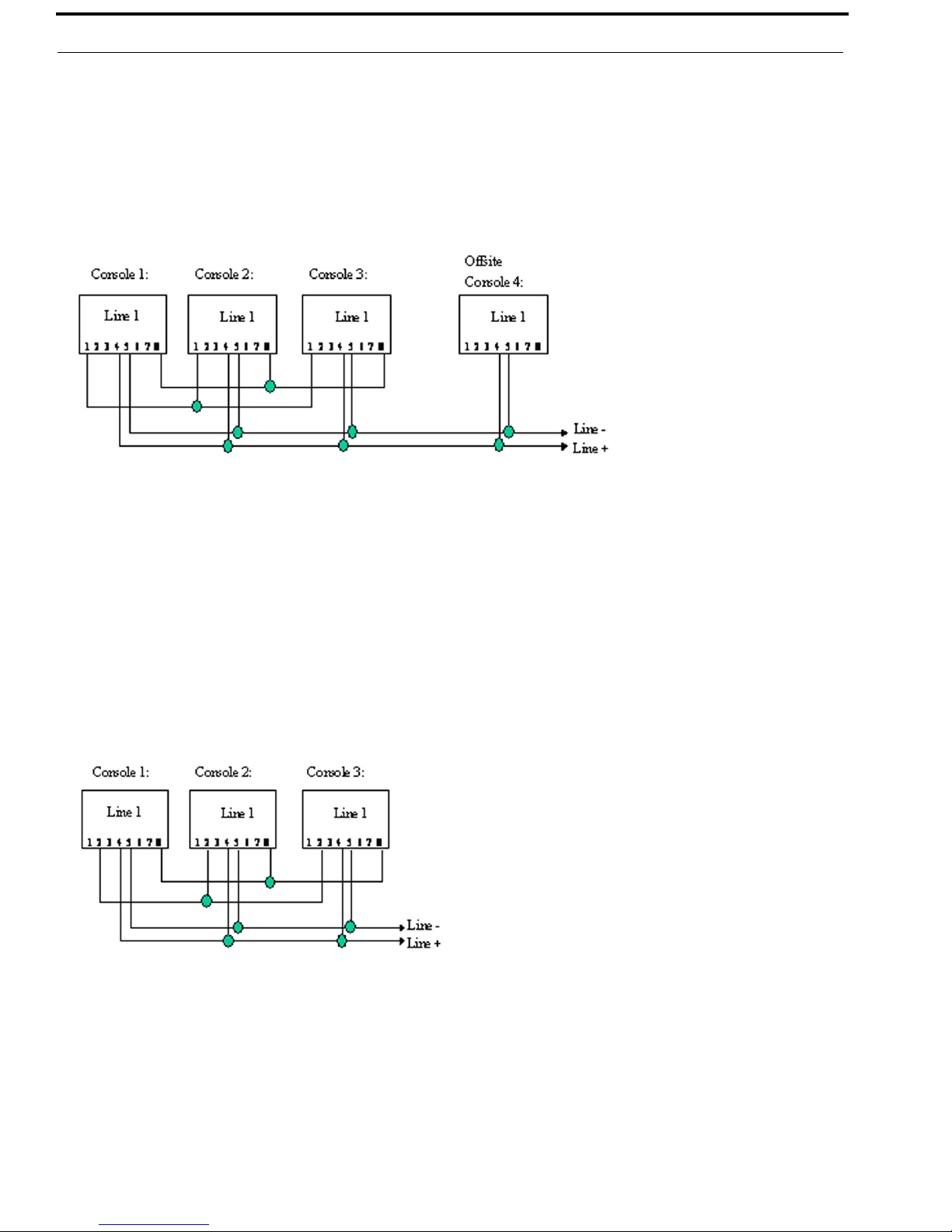
FIGURE 5. Crossmute Function Example
Feedback may be avoided by muting the receive audio of the other consoles which are in parallel with a transmitting console.
This can be accomplished by connecting pins 1 and 8 of each of the consoles to be crossmuted. as shown in Figure 5. Pin 8
must be connected to provide a common ground. Figure 5 illustrates the connections between consoles 1 through 3 that are in
the same room and when one (1) transmits, the receive audio on the other consoles is muted. Console 4 is off-site with no
possibility of feedback, therefore, it is not connected and is not muted.
NOTE: The intercom function does not work between crossmuted consoles.
Supervisor Function
FIGURE 6. Supervisor Function Example
The Supervisor function enables a console, such as the C-1616 which has the capability to drive this line, to disable all units
on a particular line. This includes both PTT and RX audio. Its connection is similar to the crossmute function. By wiring
alone, it is possible to set up only specific consoles with this feature. The connection scheme required to utilize this function is
shown in Figure 6. Pin 2 of all consoles are connected together. Pin 8 is a common ground for all consoles and is connected
together on all consoles.
Assuming console 1 has supervisory capability, when activated, Line 1 on parallel consoles 2 and 3 would then be inhibited
from both transmit and receive. In addition, the C-2000 displays SU on the seven (7) segment display if a master console, such
as the C-1616, activates the supervisor function.
Bosch Security Systems, Inc. Technical Manual F.01U.174.927 Rev 03
Page 15

C-2000 and C-2000HS Technical Manual Installation 13
Relay Contact Closure For Local Control
The relay is normally open and provides a dry contact closure during PTT functions between pins 7 and 8 of the line jack. The
relay contacts are rated at 500mA at 12VDC or 250mA at 115VAC. When using the intercom function, the relay is not
activated. If this Relay Closure is used for local control (or any other case where tone bursts are not used for signaling),
disabling the tone generation is recommended by entering the setup mode.
2-Wire/4-Wire Mode
The C-2000 comes standard with a jumper selectable 2- or 4-wire option.
NOTE: The C-2000 is shipped in the 4-wire mode.
The 2-Wire Mode is setup by the following jumper positions:
TABL E 1 . 2-Wire Mode Jumper Settings
Jumper Position
JP10 A
JP11 A
The 4-Wire Mode is setup by the following jumper positions:
TABL E 2 . 4-Wire Mode Jumper Settings
Jumper Position
JP10 B
JP11 B
The RX pair is now on pins 3 and 6 on the connector and the TX pair is on pins 4 and 5. Once the transmit and receive paths
are separated the impedance of each side must be set.
RX Side Settings
In 4-wire mode, the RX Side is jumper selectable for a 600 Ohm impedance, or 10k Ohm impedance. If only one (1) console
is on the line (no parallel consoles), then place J8 in the A position for a 600 Ohm line impedance. If more than one (1) console
is on one (1) line, then place J8 on one (1) console in the A position and all other consoles in the B position. Each console
added to the system results in line loss.
The following chart gives an indication as to how much loss can be expected. The first console in the system is set for an
impedance of 600 Ohms out (approximately). Each console added to the system thereafter is set for an impedance of
10k Ohms. The more consoles bridged on the line, the lower the line impedance and the greater the loss in audio level.
NOTE: In 2-wire mode, all consoles should have J8 in the B position.
Console # J8 Position Impedance Impedance Loss (dB)
1 A 604 604 0.0
2 B 10k 569 -0.5
3 B 10k 539 -1.0
4B10k511-1.5
5 B 10k 486 -1.9
6 B 10k 464 -2.3
Level adjustment can be made to the receive audio by entering the setup mode or adjusting the RX level poteniometer inside
the C-2000.
Bosch Security Systems, Inc. Technical Manual F.01U.174.927 Rev 03
Page 16

14 Installation C-2000 and C-2000HS Technical Manual
TX Side Settings
The C-2000 TX output circuitry has a DPDT (Double Pole Double Throw) relay that is used to connect and disconnect the TX
output transformer from the TX line based on PTT status. This allows a very large number of consoles to be attached to the
line in parallel, because only the transmitting unit is directly connected to the line. When not transmitting, the
DPDT relay is connected to 600 Ohms or open circuit depending on the number of consoles connected in parallel to the line.
If only one (1) console is attached, this unit should have J12 in the A position. This makes it the effective master and
terminates the line with 600 Ohms. If multiple consoles are connected in parallel, one (1) console should be designated as the
master by placing J12 in the A position. The remaining consoles should be designated as slaves and should have J12 placed in
the B position. In this manner, the impedance looking back into the parallel configuration of consoles is still 600 Ohms.
Figure 7 shows the basic configuration.
NOTE:
• The C-1616 could also be the master in this configuration.
• If any of the consoles connected in parallel are not C-2000’s, then all the C-2000’s should be configured
as slaves. Additionally, J14 should be used as a TX line impedance correction if there are consoles other
than the C-2000 connected in parallel. J14 position B adds another 600 Ohms to the output TX line. J14
Position A is straight through.
FIGURE 7. Master and Slave Console Configuration
Transmit Monitor
In a 4-wire system with parallel consoles, the transmit line may be monitored. The Transmit M o n i t o r is not needed in 2-wire
mode because transmit audio is already on the receive circuit. The transmit monitor, in 4-wire mode, is used to detect transmit
activity for the TX Detect LED. For more information, see “Transmit Monitor Setup” on page 15.
Level Adjustments
Transmit Side Adjustments
The transmit audio consists of multiple audio sources, microphone audio, AUX input, Function Tones, and
DTMF (Dual Tone Multiple Frequencies) tones. Each audio source is summed or generated in the
DSP (Digital Signal Processing) with the analog signal being generated on a single DAC. The following is a list of the
potentiometers that affect the transmit path.
Reference Description
R171 TX Output Level Adjustment
R105 Desk Microphone Adjustment
R115 Handset Microphone Adjustment
Bosch Security Systems, Inc. Technical Manual F.01U.174.927 Rev 03
Page 17

C-2000 and C-2000HS Technical Manual Installation 15
Mic Input level Adjustment
CAUTION: Care should be taken to avoid over-driving the input TX circuitry, as this distorts the audio. Verify you enable the
desired microphone connection in setup mode. Saying and holding the word four is a good audio level test
vocalization. Use a strong tone of voice.
To adjust the handset audio input level, do the following:
1. Connect an oscilloscope to test point TP3.
2. Adjust R115.
3. Speak into the handset.
4. Adjust the audio to approximately 3.5Vp-p.
A portion of the handset audio will be routed to the handset earpiece, this level is adjustable in setup mode. For the
Desk Microphone input, repeat the sequence only monitor test point TP2 and adjust R105. Make sure that the Desk
Microphone is at the normal distance from the operator when setting the level.
TX Output Level Adjust
The transmit level potentiometer is used to adjust the Output Level of the transmit audio so it is calibrated with the tone levels
set in setup mode. Calibration of the TX line varies depending on system variables as well as the number of consoles found in
parallel on the line. An easy way to align the console for the correct level is to press and hold the PTT key. While the console
is keyed up, the unit by default, generates a Hold tone at –20dBm. A meter reading dBm is used and R171 adjusted to read the
correct value. Also an alignment tone state 50 is provided (REV.2.3 and higher operating software).
Transmit Monitor Setup
The Transmit Monitor provides a portion of the transmit audio of a 4-wire circuit to the receive path. This allows the console
operator to listen to the transmissions of parallel console operators.
To set this level have a parallel console operator, do the following:
1. Press the intercom button.
2. Adjust R104 until the level is comfortable in the handset/headset earpiece or the speaker.
NOTE:
Make sure this feature is enabled or no audio will be passed. See “Setup Mode” on page 17.
RX Level Adjustment
The RX Level should be adjusted so the maximum level coming into the console use the entire range of the
ADC (Analog to Digital Converter), which is 0–4V. A test tone of +3dBm to -5dBm coming into the line interface is a good
value to use. Adjust R89 so the signal seen on an oscilloscope at test point TP4 is approximately 3.8Vp-p.
Bosch Security Systems, Inc. Technical Manual F.01U.174.927 Rev 03
Page 18

16 Installation C-2000 and C-2000HS Technical Manual
Bosch Security Systems, Inc. Technical Manual F.01U.174.927 Rev 03
Page 19

CHAPTER 3
Setup
Setup Mode
Entering Setup Mode
Entry into the C-2000 Setup Mode is accomplished by pressing and holding the IC and MON keys, then pressing the 2 key.
The IC and MON buttons stay lit when in setup mode.
If a PIN number is required, an EP (Enter PIN) appears in the display requesting the 4-digit number be entered. If the number
is entered incorrectly, the C-2000 displays “IP” (Incorrect PIN) and returns to user mode. No PIN number is required if the
system defaults are set. Default values can be restored to the unit by pressing and holding the function up and function down
keys when power is applied to the unit. If a PIN number has been set, it is requested before resetting to default values.
If the PIN is entered incorrectly, the C-2000 does not reset its values to default and will enter the user mode.
PIN numbers can be enabled, disabled, or changed in Setup Mode, see Setup State 1 PIN Number Change on page 21.
If the PIN number is lost or forgotten, a system override is available that sets all parameters back to default.
To reset the system parameters, do the following:
3. Power down the unit.
4. Open the case.
5. Disconnect the speaker.
6. Place test jumper J17 in the A position.
7. Power up the unit.
This mode resets defaults and does a system test. The C-2000 has now stored system defaults, which includes no PIN
number.
8. Power down the unit.
9. Place J17 in the B position.
10. Connect the speaker.
11. Close the case.
12. Power up the unit.
Bosch Security Systems, Inc. Technical Manual F.01U.174.927 Rev 03
Page 20

18 Setup C-2000 and C-2000HS Technical Manual
Exiting Setup Mode
Exiting Setup Mode is done in the same manner as entering setup mode.
1. Press and hold the IC and MON keys.
2. Press the 2 key.
The user returns to normal operation mode.
NOTE: Settings are saved on exit.
To save settings before exiting setup mode, do the following:
1. Press and hold the IC and MON keys.
2. Press the D key.
Maneuvering Through Setup Mode
Setup Mode Control Keys
The main control keys are:
Volume Up and Down - Selects the setup state by scrolling up and down through the allowed states.
Function Up and Down - Selects the setup option for the current setup state by scrolling through the allowed options
for that state.
DTMF Found Key (#) - Used as the Enter key. Pressing this key enters the current option for the current state. It also
takes you into a more complicated mode if more than a simple enable or disable is required.
DTMF Star Key (*) - Used as the Escape key. Pressing this key exits without saving from certain setup states that
require it.
NOTE: Only a few states use this key.
DTMF A and B Keys - These keys are used to program Function Tone frequencies main and sub-tone. It is also
used to select clone mode master or slave.
IC and D Key - Pressing and holding IC, then pressing D saves the changes made to setup mode.
IC and MON Keys - Pressing these keys together while in the PIN change state disables the PIN.
NOTE: This key sequence is not used in any other state.
Transmit Key - This key is used to display the current setup state, once the display has changed to the setup
option.
Setup Mode Philosophy
Once Setup Mode is entered, the operator uses the volume up and down keys to select the setup state. The setup state is the
system function that the operator wishes to change or enable. The display shows the setup state number and both decimal
points for one (1) second and then change to the Setup State option number, with no decimal point, that is currently
programmed.
If you want to review the setup state while the set up option is being displayed, simply press the TRANSMIT key on the front
panel and the current setup state displays as long as the key is held. Once you have scrolled to your desired setup state and the
display has changed to that states currently programmed setup option, the operator can use the function up and function down
keys to scroll to the appropriate setup option.
Bosch Security Systems, Inc. Technical Manual F.01U.174.927 Rev 03
Page 21

C-2000 and C-2000HS Technical Manual Setup 19
The display shows the setup option number and no decimal points. The selection scrolls to those option values available to that
setup state, i.e., an enable/disable setup state has option 1 and 2, with 1=enable and 2=disable and no other. Now, pressing the
Enter (#) key programs the selected option for the current state. Once programming completes, the display shows
OC (Option Changed), then display the current setup state.
Saving the changes made to a setup state is done by pressing and holding IC and pressing D. The display shows
SS (Settings Saved) and then returns to the current Setup State. Exiting setup mode automatically saves the settings. If the
settings are not saved and power is lost, the changes will be discarded.
There are certain setup states with more complex user interface features. For more information about status states,
see Setup Mode on page 17.
TABL E 3 . Setup States and Setup State Options
Setup State
Setup State Description
Number
0 PIN Number Entry/Idle Automatically entered when Setup Mode is accessed.
1 PIN Number Change Used to change the Setup Mode PIN number.
2 Guard/Hold Tone Frequency Selects between 2175Hz and 2300Hz.
3 Guard Tone Level Sets the level of the Guard tone.
4 Guard Tone Duration Sets the Guard tone duration
5 Hold Tone Level Sets the Hold tone level
6 Hold Tone Hang Time Sets the time PTT and the hold tone is held after the Key release.
7 Function Tone Level Sets the level of the Function Tone.
8 Function Tone Duration Sets the duration of the Function Tone.
9 Single/Dual Function Tone
Mode
10 Function Tone Frequency
Single mode F-Tone frequency.
Select Mode
11 MON Frequency Selection Set Frequency of the monitor tone. 2050Hz default.
12 DTMF Keypad Enable/
Disable
13 DTMF Tone Level Set the level of the DTMF tone generator.
14 DTMF Hang Timer Time between DTMF tones that the Guard/Hold tone will wait.
15 MIC AGC
16 RX AGC
17 Main Speaker with Handset
Enable/Disable
18 Single Frequency Telephone
a
Mode
19 Auxiliary Speaker Enable/
Disable
20 Function Tone Enable/Disable Select any F-tone from 1–99 to enable or disable, either mode.
21 Crossmute Enable/Disable
22 Minimum Speaker Audio Level
Min Speaker audio level Enable/Disable:
Enable/Disable
23 Handset Mic Gain Setting Set the gain used for input audio on the handset microphone.
24 Desk Mic Gain Setting Set the gain used for input audio on the desk microphone.
25 AUX Port Gain Setting Set the gain used for input audio on the auxiliary port.
26 Panel Mic Gain Setting
27 RX Gain Setting Set the gain for the input RX audio.
28 TX Gain Setting Set the gain for the output TX audio.
29 Clone Mode Entry Enter the Clone mode. Press enter key, then select RX or TX.
30 Duplex Mode Enable/Disable
Bosch Security Systems, Inc. Technical Manual F.01U.174.927 Rev 03
Page 22

20 Setup C-2000 and C-2000HS Technical Manual
TABLE 3. Setup States and Setup State Options
Setup State
Setup State Description
Number
31 Handset Enable/Disable
32 Monitor Mode Enable/Disable
33 Tone/Local Mode Enable/
Disable
34 Squelch Threshold Level Set the threshold the squelch breaks at.
35 Squelch Enable/Disable
36 Squelch Hang Timer Set the time the squelch stays on after the threshold is broken.
37 TX Monitor Enable/Disable
38 Tone Detector Threshold Set the threshold level of the tone detector.
39 Headset Hook Switch Enable/
Disable
40 TX Delay Period Set the amount of time TX output audio is delayed. 500ms max.
41 Desk Microphone Enable/
Disable
42
43
44
45
Ring Type Select
EMSTEL Enable/Disable
DTMF Sequence Entry
Ring Duration Entry
46 DTMF Sequence Enable/
a
a
a
Select the type of annunciation on incoming call.
a
Enable EMS Telephone mode.
Program the DTMF strings or sequences.
Program the number of rings that will occur before no answer.
DTMF Sequence Enable/Disable:
Disable
47 Function Tone Delay Program the amount of delay between F-up, F-down and F-tone launch.
48 Parallel Update Enable/
Disable
49 Alert Tone Enable/Disable
50 Alignment Tone On/Off Turns a test tone on and off.
a. Special Software Option
Setup Mode Navigation Overview
IC, MON and 2 - Used to access and exit Setup Mode.
Volume Up/Down - Set the current Setup State. Number displayed with both decimal points lit.
Function Up (
)/Down (
) Set the Setup State option. Number displayed with no decimal points lit.
ENTER (#) - Key used to enter a value or mode. OC (Option Changed) or mode indication
displayed after press.
IC and D - Used to save any change made in Setup Mode. SS (Saved Settings) is displayed
momentarily.
NOTE:
• Any other keystroke of importance is detailed in the Setup State section where it is used.
• If no PIN is required, then upon entering the Setup Mode key sequence (IC-MON-2) the user goes
directly to setup state 1.
• Descriptions of each setup variable appear in the following sections. In all option menus, the default
option is denoted with an * (asterisk).
Bosch Security Systems, Inc. Technical Manual F.01U.174.927 Rev 03
Page 23

C-2000 and C-2000HS Technical Manual Setup 21
Setup State 0 PIN Number Entry/Idle
The PIN Number Entry/Idle setup state is automatically entered when the setup mode key sequence is entered
(i.e. IC-MON-2). If a PIN number is required, EP (Enter PIN) is displayed. At this point, the user has to enter a 4-digit PIN
number. The display sequences through 1,2,3,4 as the PIN is entered. If the PIN is correct, setup mode automatically goes to
setup state 1, PIN Number Change. The user is now free to scroll through the Setup States.
If the PIN is entered incorrectly, an IP displays and the C-2000 returns to the normal operation mode.
If no PIN is required, then upon entering the setup mode key sequence (IC-MON-2) the user goes directly to setup state 1.
Setup State 1 PIN Number Change
The PIN Number Change setup state is used to change the PIN number. Enter Setup State 1 using the Volume Up/Down keys.
Then press the Enter (#) key. The display shows EP (Enter PIN) expecting a new PIN number to be entered. The display
sequences through 1,2,3,4 as the new PIN is entered. Once 4 digits have been entered, the display shows
EP (Enter PIN) requesting the PIN again as a confirmation.
If the PINs match, the display shows PC (PIN Changed).
If the PIN’s do not match, the display shows IP (Incorrect PIN) and you are forced back to normal operation mode.
To remove a PIN, do the following:
1. Press the Enter (#) key.
Display shows EP (Enter PIN) as if you were changing the PIN.
2. Press and hold the IC key.
3. Press the MON key.
Display shows PD (PIN Disabled).
NOTE: The changes are automatically saved.
Setup State 2 Guard/Hold Tone Frequency
The Guard/Hold Tone Frequency setup state, see Table 4, is used to set the frequency of the guard and hold tones. Two (2)
values are valid for setup frequencies.
To set the guard/hold tone frequency, do the following:
1. Select the setup option using FUP/FDWN keys.
2. Press Enter (#).
Display shows OC (Option Changed).
TABL E 4 . Guard/Hold Tone Frequency
Option Frequency
1 (default) 2175Hz
2 2300Hz
Bosch Security Systems, Inc. Technical Manual F.01U.174.927 Rev 03
Page 24

22 Setup C-2000 and C-2000HS Technical Manual
Setup State 3 Guard Tone Level
The Guard Tone Level setup state is used to set the level of the guard tone. The guard tone has a 40dB range. The values in
between those shown in Table 5 are valid as well. For example 25 would result in an output level of -6dB for the guard tone.
To set the guard tone level, do the following:
1. Select the setup option using FUP/FDWN keys.
2. Press Enter (#).
Display shows OC (Option Changed).
TABLE 5. Guard Tone Level
Option Level
1 -30dB
11 -20dB
21 -10dB
25 -6dB
31 0 dB
41 (default) +10dB
Setup State 4 Guard Tone Duration
The Guard Tone Duration setup state can vary from 0 to 500ms and is configurable to the nearest 10ms. The setup option is
offset by one (1) and multiplied by 10. Any value between those in Table 6 is valid.
To set the tone duration, do the following:
1. Select the setup option using FUP/FDWN keys.
2. Press Enter (#).
Display shows OC (Option Changed).
TABLE 6. Guard Tone Duration
Option Duration
10 ms
14 (default) 130ms
51 500ms
Setup State 5 Hold Tone Level
The Hold Tone Level setup state is used to set the level of the hold tone. The Hold tone has a 40dB range. The values in
between those shown in Table 7 are valid as well, for example 25 would result in an output level of -6dB for the hold tone.
To set the hold tone level, do the following:
1. Select the setup option using FUP/FDWN keys.
2. Press Enter (#).
Display shows OC (Option Changed).
TABLE 7. Hold Tone Level
Option Level
1 -30dB
11 (default) -20dB
21 -10dB
25 -6dB
31 0 dB
41 +10dB
Bosch Security Systems, Inc. Technical Manual F.01U.174.927 Rev 03
Page 25

C-2000 and C-2000HS Technical Manual Setup 23
Setup State 6 Hold Tone PTT Hang Time
The PTT Hang Time Duration can vary from 0 to 500ms and is configurable to the nearest 10ms. The setup option is offset
by one (1) and multiplied by 10. The purpose of this setting is to allow some programmable amount of time for the hold tone
to continue after the PTT is released. This allows for the PTT to be released and pressed again without re-sending the
guard-function sequence.
To set the PTT hang time duration, do the following:
1. Select the setup option using FUP/FDWN keys.
2. Press Enter (#).
Display shows OC (Option Changed).
TABL E 8 . Hold Tone PTT Hang Time
Option Duration
10 ms
21 (default) 200ms
51 500ms
Setup State 7 Function Tone Level
The Function Tone Level is used to set the level of the Function Tone, which has a 40dB range. The values in between those
shown in the Table 9 are valid as well, for example 25 would result in an output level of -6dB for the Function Tone.
To set the function tone level, do the following:
1. Select the setup option using FUP/FDWN keys.
2. Press Enter (#).
Display shows OC (Option Changed).
TABL E 9 . Function Tone Level
Option Level
1 -30dB
25 -6dB
31 (default) 0 dB
41 +10dB
Setup State 8 Function Tone Duration
The Function Tone Durations can vary from 0 to 500ms and is configurable to the nearest 10ms.
GLOBAL DURATIONS: Use the function control keys to adjust the duration option (1–51), do the following:
1. Press A for the Function Tone duration to be globally changed. This includes the main and sub-tones.
Display shows OC (Option Changed).
NOTE: Do not press # for global changes.
INDIVIDUAL DURATIONS: To modify FT Function Tone durations, do the following:
1. Press Enter (#).
Display shows FD (Function Duration).
NOTE: Function Tone one (1) duration mode has been entered.
Bosch Security Systems, Inc. Technical Manual F.01U.174.927 Rev 03
Page 26

24 Setup C-2000 and C-2000HS Technical Manual
Use the instructions for Setup State 10 Function Tone Frequency setup, only applied to the duration Table 10 for Setup State 8.
TABLE 10. Function Tone Duration
Option Duration
10ms
5 (default) 40ms
51 500ms
Setup State 9 Single/Dual Function Tone Mode
Single/Dual Function Tone Mode is used to set whether the C-2000 generates single or dual function tones. In the single
Function Tone mode, Function Tones F1–F16 are valid and is sent per the programmed values of frequency, duration, and
level. In the dual tone mode, two (2) function tones are sent out in which the first function tone is the tens digit and the second
function tone is the ones digit. F10 is used as zero (0). In the dual mode it is important to remember the settings for F1–F10 are
used for the digits. Remember, the frequencies programmed for F1–F10 will be transmitted to the tone remote. If the user
modifies the frequencies of F1–F10, the tone remote at the radio must be capable of Dual Function Tone mode and the
frequencies must be modified to match the C-2000.
To set the single/dual function tone mode, do the following:
1. Select the setup option using FUP/FDWN keys.
2. Press Enter (#).
Display shows OC (Option Changed).
TABLE 11. Single Dual Function Tone Mode
Option Setting
1 (default) Single Tone
2 Dual Tone
Setup State 10 Function Tone Frequency
Function Tone Frequency is used to set the frequency of a particular function tone, it is a more complex setup state. Each
Function Tone has a main tone and one (1) sub-tone. Once the user maneuvers to Setup State 10 using the
VOLUME UP/DOWN keys, they must enter the Function Tone Frequency setup mode. Prior to entry, the FUNCTION UP/
DOWN keys have no effect on the setup option. Function Tone Frequency setup mode has yet to be started.
To start Function Tone Frequency setup mode, do the following:
1. Press the ENTER (#) key with Setup State 10 as the current state.
Notice that the display changes to FF, the system is now in Function Tone Frequency setup mode.
In this mode, the FUNCTION UP/DOWN () keys are used to select the Function Tone the user wishes to modify.
The allowable values are 1–99. Pressing FUP () or FDWN () causes the display to scroll through these values, with
no decimal point displayed. Once scrolling has stopped, the display changes to setup option 1, with both decimal points
displayed.
Once the user has selected the function tone to be modified, use the VOLUME UP/DOWN keys to select the frequency for the
current function tone, based on. The display scrolls through the setup option numbers with both decimal points displayed.
With the display showing the frequency setup option, the user can momentarily change the display to the current function tone
selected by pressing and holding the TRANSMIT key. The current function tone displays with no decimal points until the key
is released, after which the display returns to the setup option.
Once the user has selected the function tone and the frequency, programming can begin. Remember each function tone has a
main and a sub-tone. These are programmed by pressing DTMF A for the main tone or DTMF B for the sub-tone. Once the
main or sub-tone has been selected, the display shows OC (Option Changed), then return to the current function tone number.
Bosch Security Systems, Inc. Technical Manual F.01U.174.927 Rev 03
Page 27

C-2000 and C-2000HS Technical Manual Setup 25
Exiting and saving the changes to the Function Tone Frequency setup mode can be achieved in the following manner: First,
exit the function tone frequency setup mode by pressing the Escape key (*). This takes you to the entry point for setup state 10.
From here the user navigates to any other setup state.
To save the changes, do the following:
1. Simply press and hold the IC key.
2. Press DTMF D.
Display will show SS (Saved Settings).
TABLE 12. Available Function and Monitor frequencies.
Option Frequency Option Frequency Option Frequency
1 400Hz 19 1300Hz 37 2200Hz
2-F16 450Hz 20-F7 1350Hz 38 2250Hz
3 500Hz 21 1400Hz 39 2300Hz
4-F15 550Hz 22-F6 1450Hz 40 2350Hz
5 600Hz 23 1500Hz 41 2400Hz
6-F14 650Hz 24-F5 1550Hz 42 2450Hz
7 700Hz 25 1600Hz 43 2500Hz
8-F13 750Hz 26-F4 1650Hz 44 2550Hz
9 800Hz 27 1700Hz 45 2600Hz
10-F12 850Hz 28-F3 1750Hz 46 2650Hz
11 900Hz 29 1800Hz 47 2700Hz
12-F11 950Hz 30-F2 1850Hz 48 2750Hz
13 1000Hz 31 1900Hz 49 2800Hz
14-F10 1050Hz 32-F1 1950Hz 50 2850Hz
15 1100Hz 33 2000Hz 51 2900Hz
16-F9 1150Hz 34-MON 2050Hz 52 2950Hz
17 1200Hz 35 2100Hz 53 3000Hz
18-F8 1250Hz 36 2150Hz
NOTE: In the options with a Function Number (F1-F16) and MON in the cell, indicate the default frequencies for that
Function Tone.
Function Tone setup mode overview:
FUNCTION UP (
) and DOWN (
): Set the current Function Tone to be modified.
VOLUME UP/DOWN: Set the current Function Tone Frequency.
DTMF A and B: Select the main or sub Function Tone to be programmed.
TRANSMIT key: Show the current Function Tone once the display changes to the setup
option.
DTMF *: Escape out of Function Tone Frequency setup mode.
IC and D: Method used to save the changes made in Setup Mode.
Bosch Security Systems, Inc. Technical Manual F.01U.174.927 Rev 03
Page 28

26 Setup C-2000 and C-2000HS Technical Manual
Setup State 11 Monitor Frequency Select
The Monitor Frequency Select setup state is used to set the frequency of the monitor function tone.
To see the available options and the default monitor function tone frequency, do the following:.
1. Select the setup option using FUP/FDWN keys.
2. Press Enter (#).
Display shows OC (Option Changed).
Setup State 12 DTMF Keypad Enable/Disable/Enable (without PTT)
The DTMF Keypad Enable/Disable/Enable setup state is used to enable/disable the keypad in normal operation mode.
Setup State option:
1=Enable*
2=Disable
3=Enable without PTT tone being sent
To enable/disable the DTMF keypad, do the following:
1. Select the setup option using FUP/FDWN keys.
2. Press Enter (#).
Display shows OC (Option Changed).
Setup State 13 DTMF Tone Level
The DTMF Tone Level Setup state has a 40dB range. The values in between those shown in the Table 13 are valid as well, for
example, 25 results in an output level of -6dB for the DTMF Tone.
To configure DTMF tone level, do the following:
1. Select the setup option using FUP/FDWN keys.
2. Press Enter (#).
Display shows OC (Option Changed).
TABLE 13. DTMF Tone Level
Option Level
1 -30dB
11 -20dB
21 (default) -10dB
31 0 dB
41 +10dB
Bosch Security Systems, Inc. Technical Manual F.01U.174.927 Rev 03
Page 29

C-2000 and C-2000HS Technical Manual Setup 27
Setup State 14 DTMF Hang Timer
The DTMF Hang Timer setup state is used to allow the user a programmable amount of time to release one (1) DTMF key
and press another without the hold tone being stopped and requiring the unit to resend the guard. Function tones can vary from
0 to 980ms and is configurable to the nearest 10ms. This timer has no effect if PTT or IC is already pressed.
TABLE 14. DTMF Hang Time
Option Duration
10 ms
5 40ms
51 (default) 500ms
99 980ms
Setup State 15 MIC AGC Enable/Disable
The MIC AGC Enable/Disable is used to enable/disable AGC on all MIC inputs.
Setup State option:
1=Enable*
2=Disable
To enable/disable AGC on all MIC inputs, do the following:
1. Select the setup option using FUP/FDWN keys.
2. Press Enter (#).
Display shows OC (Option Changed).
Setup State 16 RX AGC Enable/Disable
The RX AGC Enable/Disable is used to enable/disable AGC on the receive audio.
Setup State option:
1=Enable*
2=Disable
To enable/disable AGC on the receive audio, do the following:
1. Select the setup option using FUP/FDWN keys.
2. Press Enter (#).
Display shows OC (Option Changed).
Bosch Security Systems, Inc. Technical Manual F.01U.174.927 Rev 03
Page 30

28 Setup C-2000 and C-2000HS Technical Manual
Setup State 17 Main Speaker with Handset Enable/Disable
The Main Speaker with Handset Enable/Disable allows receive handset audio to be played on the main speaker, as well as
the handset earpiece.
Setup State option:
1=Enable*
2=Disable
To enable/disable the main speaker and handset, do the following:
1. Select the setup option using FUP/FDWN keys.
2. Press Enter (#).
Display shows OC (Option Changed).
Setup State 18 SF Mode Enable/Disable (Special Software Option)
2
The SF (Single-Frequency) Mode Enable/Disable setup state is used to enable/disable mode of operation. This mode
requires the device operate in a telephone station configuration with 4-wire analog supervision SF signaling.
Setup State option:
1=Enable
2=Disable*
To enable/disable SF mode, do the following:
1. Select the setup option using FUP/FDWN keys.
2. Press Enter (#).
Display shows OC (Option Changed).
NOTE: If SF Mode is enabled, EMSTEL Mode is disabled.
Setup State 19 Aux Speaker Enable/Disable
The Aux Speaker Enable/Disable setup state is used to enable/disable the auxiliary speaker capability.
Setup State option:
1=Enable
2=Disable*
To enable/disable the auxiliary speaker capability, do the following:
1. Select the setup option using FUP/FDWN keys.
2. Press Enter (#).
Display shows OC (Option Changed).
2. This mode is not available unless activated at the factory. Once activated it will become a standard setup state.
Bosch Security Systems, Inc. Technical Manual F.01U.174.927 Rev 03
Page 31

C-2000 and C-2000HS Technical Manual Setup 29
Setup State 20 Function Tone Enable/Disable
The Function Tone Enable/Disable setup state is used to enable/disable a specific function tone. Allowed setup options are
1–99 or all the possible function tones.
To modify the status of a function tone, do the following:
1. Select the setup option using FUP/FDWN keys.
2. To enable the Function Tone, press DTMF A.
3. To disable the Function Tone, press DTMF B.
Display shows OC (Option Changed).
NOTE: To determine the status of the Function Tone, observe the display as the option scrolls:
• Right decimal point is displayed the Function Tone is enabled.
• No decimal point is displayed the Function Tone is disabled.
Setup State 21 Crossmute Output Enable/Disable
The Crossmute Output Enable/Disable setup state is used to set whether the C-2000 pulls the crossmute pin on the line
connector low during a PTT/IC sequence.
Setup State option:
1=Enable
2=Disable*
To enable/disable crossmute output, do the following:
1. Select the setup option using FUP/FDWN keys.
2. Press Enter (#).
Display shows OC (Option Changed).
Setup State 22 Min Speaker Level Enable/Disable
The Min Speaker Level Enable/Disable is used to set whether the C-2000 enforces a minimum speaker level. Enabling this
guarantees the operator cannot turn the volume completely off. The volume control range is 0–25, with zero (0) being muted
audio and 25 being full volume. The possible setup options are 1–25 or the full volume control range, except zero (0) or muted.
To enable/disable min speaker level, do the following:
1. Select the setup option using FUP/FDWN keys.
2. Press Enter (#).
Display shows OC (Option Changed).
To clear the minimum speaker value, do the following:
1. Press the Escape (*) key.
Display shows OC (Option Changed).
NOTE: The default value for this feature is zero (0), or no minimum level.
Bosch Security Systems, Inc. Technical Manual F.01U.174.927 Rev 03
Page 32

30 Setup C-2000 and C-2000HS Technical Manual
Setup State 23 Handset Mic Level
The Handset Mic Level setup state is used to set the level of the handset microphone jack input. The allowable range is
–10dB to +10dB. The values in between those shown in Table 15 are valid as well, for example 12 would result in an output
level of +1dB for the level setting.
To set the level of the handset microphone jack input, do the following:
1. Select the setup option using FUP/FDWN keys.
2. Press Enter (#).
Display shows OC (Option Changed).
TABLE 15. Handset Mic Level
Option Level
1 -10dB
11 (default) 0 dB
12 +1dB
21 +10dB
Setup State 24 Deskmic Level
The Deskmic Level setup state is used to set the level of the deskmic jack input. The allowable range is –10dB to +10dB. The
values in between those shown in Table 16 are valid as well, for example 12 would result in an output level of +1dB for the
level setting.
To set the level of the deskmic jack input, do the following:
1. Select the setup option using FUP/FDWN keys.
2. Press Enter (#).
Display shows OC (Option Changed).
TABLE 16. Deskmic Level
Option Level
1 -10dB
11 (default) 0 dB
12 +1dB
21 +10dB
Setup State 25 Aux Input Port Level
The Aux Input Port Level setup state is used to set the level of the Aux input port. The allowable range is –10dB to +10dB.
The values in between those shown in Table 17 are valid as well, for example 12 would result in an output level of +1dB for
the level setting.
To set the level of the aux input port, do the following:
1. Select the setup option using FUP/FDWN keys.
2. Press Enter (#).
Display shows OC (Option Changed).
TABLE 17. Aux Input Port Level
Option Level
1 -10dB
11 (default) 0 dB
12 +1dB
21 +10dB
Bosch Security Systems, Inc. Technical Manual F.01U.174.927 Rev 03
Page 33

C-2000 and C-2000HS Technical Manual Setup 31
Setup State 26 Panel Microphone Input Level
The Panel Microphone Input Level setup state is used to set the level of the panel microphone input level. The allowable
range is –10dB to +10dB. The values in between those shown in Table 18 are valid as well, for example 12 would result in an
output level of +1dB for the level setting.
To set the level of the panel microphone input level, do the following:
1. Select the setup option using FUP/FDWN keys.
2. Press Enter (#).
Display shows OC (Option Changed).
TABLE 18. Panel Microphone Input Level
Option Level
1 -10dB
11 (default) 0 dB
12 +1dB
21 +10dB
Setup State 27 RX Line Jack Level
The RX Line Jack Level setup state is used to set the level of the RX line jack. The allowable range is –10dB to +10dB. The
values in between those shown in Table 19 are valid as well, for example 12 would result in an output level of +1dB for the
level setting.
To set the level of the RX line jack, do the following:
1. Select the setup option using FUP/FDWN keys.
2. Press Enter (#).
Display shows OC (Option Changed).
TABLE 19. RX Line Jack Level
Option Level
1 -10dB
11 (default) 0 dB
12 +1dB
21 +10dB
Setup State 28 TX Line Jack Level
The TX Line Jack Level setup state is used to set the level of the TX Line Jack. The allowable range is –10dB to +10dB. The
values in between those shown in Table 20 are valid as well, for example 12 would result in an output level of +1dB for the
level setting.
TABLE 20. TX Line Jack Level
Option Level
1 -10dB
11 (default) 0 dB
12 +1dB
21 +10dB
Bosch Security Systems, Inc. Technical Manual F.01U.174.927 Rev 03
Page 34

32 Setup C-2000 and C-2000HS Technical Manual
Setup State 29 Clone Mode
The Clone Mode setup state is used to copy the non-volatile memory of a properly configured unit to a generic unit, thereby
cloning one (1) unit to another.
NOTE: The software version numbers must be the same.
This setup state is the gateway to a more complex mode, so there are no setup options at first.
To setup clone mode, do the following:
1. Setup the slave to receive data and the master to transmit data. Make sure the two (2) units are properly connected.
2. The data port on the back of the C-2000 is a 3-pin port with TX, RX and GND.
3. Using a 3-wire serial cable constructed as shown in Figure 8, connect the two (2) units together.
4. Keep the cable length reasonably short.
5. Each unit is shipped with the connector plugged into the back.
FIGURE 8. Serial Cable Diagrams
To enter clone mode, do the following:
1. Press the Enter (#) key.
The display shows CL (Clone Mode). The C-2000 is waiting to be told whether it is the master (TX) or the
slave (RX).
To operate in clone mode operation, do the following:
1. Press DTMF B to place the slave unit in receive mode.
There is no indication that the unit is in receive mode. The slave will wait indefinitely for the master to begin sending
data. The slave unit is ready to receive, the user begins transmitting with the master.
2. Press DTMF A on the master will start the transmission.
The slave unit will receive the last packet, after approximately five (5) seconds.
3. Calculate the checksum.
Display CC (Clone Complete) or EE (Error) if checksum fails. This concludes the cloning process.
To exit clone mode, do the following:
1. Press the ESCAPE(*) key.
Display shows CC (Clone Complete).
NOTE: The C-2000 is back in normal setup mode and waiting for the next setup state.
Bosch Security Systems, Inc. Technical Manual F.01U.174.927 Rev 03
Page 35

C-2000 and C-2000HS Technical Manual Setup 33
Clone Mode Overview
ENTER(#) key: Used to enter Clone Mode.
ESCAPE(*) key: Used to exit Clone Mode.
DTMF B: Sets up the slave/receive mode. Must be done prior to receiving data.
DTMF A: Starts data transmission from the master. Slave will indicate Clone Complete.
Setup State 30 Full Duplex Mode Enable/Disable
The Full-Duplex Mode Enable/Disable is used to set whether the C-2000 has the full-duplex mode of operation enabled or
disabled. Full-Duplex allows the operator to listen to incoming traffic during a PTT sequence.
Setup State option:
1=Enable*
2=Disable
To enable/disable full duplex mode, do the following:
1. Select the setup option using FUP/FDWN keys.
2. Press Enter (#).
Display shows OC (Option Changed).
Setup State 31 Handset Enable/Disable
The Handset Enable/Disable is used to set whether the C-2000 has the handset enabled or disabled. This is used to determine
the routing of receive audio.
Setup State option:
1=Enable*
2=Disable
To enable/disable the handset, do the following:
1. Select the setup option using FUP/FDWN keys.
2. Press Enter (#).
Display shows OC (Option Changed).
Bosch Security Systems, Inc. Technical Manual F.01U.174.927 Rev 03
Page 36

34 Setup C-2000 and C-2000HS Technical Manual
Setup State 32 Auto-Monitor Enable/Disable
The Auto-Monitor Enable/Disable is used to set whether the C-2000 has the monitor set to automatic or manual. In the case
of automatic, if the handset is installed the MON burst is sent when an off-hook is sensed. In the manual mode, the MON key
must be pressed to send the MON burst to the tone remote.
Setup State option:
1=Enable
2=Disable*
To enable/disable auto-monitor, do the following:
1. Select the setup option using FUP/FDWN keys.
2. Press Enter (#).
Display shows OC (Option Changed).
Setup State 33 Tone/Local Mode
The Tone/Local mode is used to determine whether the C-2000 should send the Guard-Func-Hold sequence for PTT. If the
unit is set to local mode, a PTT closes the relay attached to the line jack.
Setup State option:
1=Tone*
2=Local
To, set the tone/local mode, do the following:
1. Select the setup option using FUP/FDWN keys.
2. Press Enter (#).
Display shows OC (Option Changed).
Setup State 34 Squelch Level
The Squelch Level is used to set the level at which the squelch, if enabled, opens up the receive audio. This function can be
used with an incoming tone to determine the set point. If an incoming tone is present, as soon as the value is entered from
Table 21, the speaker either opens up or mutes. The values in between those shown in Table 21 are valid as well.
To set the squelch level, do the following:
1. Select the setup option using FUP/FDWN keys.
2. Press Enter (#).
Display shows OC (Option Changed).
TABLE 21. Squelch Level
Option Level
1 -30dB
21* -10dB
31 0 dB
Bosch Security Systems, Inc. Technical Manual F.01U.174.927 Rev 03
Page 37

C-2000 and C-2000HS Technical Manual Setup 35
Setup State 35 Squelch Enable/Disable
The Squelch Enable/ Disable enables or disables the squelch function. If disabled, all audio, no matter the incoming level, is
played through to the speaker.
Setup State option:
1=Enable
2=Disable*
To enable/disable the squelch, do the following:
1. Select the setup option using FUP/FDWN keys.
2. Press Enter (#).
Display shows OC (Option Changed).
Setup State 36 Squelch Hang Time
The Squelch Hang Time duration can vary from 1 to 60s and is configurable to the nearest second. The squelch hang time
determines the amount of time the squelch stays open after a valid signal is removed. The Setup State option number is the
value, in seconds, to be programmed. The default value is 10 seconds.
To configure squelch hang time, do the following:
1. Select the setup option using FUP/FDWN keys.
2. Press Enter (#).
Display shows OC (Option Changed).
Setup State 37 TX Monitor Enable/Disable
The TX Monitor Enable/Disable enables or disables the TX monitor function. In 4-wire mode, if TX monitor is enabled,
parallel TX audio is routed to the speaker. Also, the tone detector algorithm blinks the TRANSMIT LED when threshold
surpassing hold tone is detected on the TX line. In 2-wire mode, this feature is not applicable.
Setup State option:
1=Enable*
2=Disable
To enable/disable TX monitor function, do the following:
1. Select the setup option using FUP/FDWN keys.
2. Press Enter (#).
Display shows OC (Option Changed).
Bosch Security Systems, Inc. Technical Manual F.01U.174.927 Rev 03
Page 38

36 Setup C-2000 and C-2000HS Technical Manual
Setup State 38 Tone Detector Threshold
The Tone Detector is used to set the threshold for the tone detectors, there are two (2) thresholds that may be adjusted.
Threshold A is for a TX Hold Tone. If the Hold tone causes the threshold to be surpassed, the TRANSMIT LED starts
blinking. This indicates a parallel transmission. Possible values range from 100–9900 the default is 4500.
To set the threshold A tone detector, do the following:
1. Select the setup option using FUP/FDWN keys.
2. Press DMTF A.
Display shows OC (Option Changed).
Threshold B is for the parallel update function tone. If parallel update is enabled and a parallel console transmits the Guard/
Function tone sequence, which causes this tone detector threshold to be surpassed, the unit switches the current function tone
value to that decoded and update the display.
To set the threshold B tone detector, do the following:
1. Select the setup option using FUP/FDWN keys.
2. Press DMTF B.
Display shows OC (Option Changed).
TABLE 22. Tone Detector Threshold
Option Threshold A Threshold B
1 100 10000
25 2500 250000
45 4500 (default) 450000 (default)
75 7500 750000
99 9900 990000
NOTE: When this Setup State option number is first displayed it will show the default or the value last programmed,
whether threshold A or B.
Setup State 39 Headset Enable/Disable
The Headset Enable/Disable is used to enable/disable headset control of the hook switch. If enabled, a headset can cause the
system to be taken off hook.
Setup State option:
1=Enable
2=Disable*
To enable/disable headset control of the hook switch, do the following:
1. Select the setup option using FUP/FDWN keys.
2. Press Enter (#).
Display shows OC (Option Changed).
Bosch Security Systems, Inc. Technical Manual F.01U.174.927 Rev 03
Page 39

C-2000 and C-2000HS Technical Manual Setup 37
Setup State 40 TX Delay Period
The TX Delay Period is the amount of time the C-2000 spools audio before transmitting. The maximum delay period is
500ms.
To set the TX delay period, do the following:
1. Select the setup option using FUP/FDWN keys.
2. Press Enter (#).
Display shows OC (Option Changed).
Option Period
10
2 100ms
3 200ms
4 300ms
5 400ms
6 500ms
Setup State 41 Desk Microphone Enable/Disable
The Desk Microphone Enable/Disable is used to enable/disable the desk microphone.
Setup State option:
1=Enable
2=Disable*
To enable/disable the desk microphone, do the following:
1. Select the setup option using FUP/FDWN keys.
2. Press Enter (#).
Display shows OC (Option Changed).
Setup State 42 Ring Type Select (Special Software Option)
The Ring Type Select is used to select the type of annunciation the C-2000 uses in SF or EMSTEL modes of operation. There
are eight (8) different rings to select from, all cadences are one (1) second annunciation, four (4) second ring period. Possible
notes are, from lowest to highest: A=440Hz, B=494Hz, C=523Hz, D=587Hz, E=659Hz, F=698Hz, G=784Hz, 2A=880Hz.
To set the ring type select, do the following:
1. Select the setup option using FUP/FDWN keys.
2. Press Enter (#).
Display shows OC (Option Changed).
Setup Option Note One Note Two Note Three Note Four
1EAEA
2AECG
3FGAC
4GDAD
5ACEG
6GECA
7GGCC
8 G 2A G 2A
Bosch Security Systems, Inc. Technical Manual F.01U.174.927 Rev 03
Page 40

38 Setup C-2000 and C-2000HS Technical Manual
Setup State 43 EMSTEL Enable/Disable (Special Software Option)
The EMSTEL Enable/Disable is used to enable/disable the EMSTEL mode of operation. This mode is to operate in
multi-party, 4-wire private network. It uses two (2) digit DTMF signaling.
Setup State option:
1=Enable
2=Disable*
To enable/disable EMSTEL, do the following:
1. Select the setup option using FUP/FDWN keys.
2. Press Enter (#).
Display shows OC (Option Changed).
NOTE: If SF Mode is enabled, EMSTEL Mode is disabled. Disable SF Mode before exiting setup mode.
Setup Option Assignment
1D00
2D01
3D02
4D03
5D04
6D05
7D06
8D07
9D08
10 D09
11 D10
12 D11
13 D12
14 D13
15 D14
16 Receive/D15
Setup State 44 DTMF Sequence Entry
The DTMCF Sequence Entry is used to program the DTMF sequences which cause annunciation if received or is transmitted
when the D key is pressed and the sequence assignment number follows directly, providing the mode is enable
(see DTMF Sequence Enable/Disable and DTMF Keypad Enable/Disable).
NOTE: When this feature is enabled, the D key is unavailable for normal DTMF use.
To enter a DTMF sequence, do the following:
1. Select the setup option using FUP/FDWN keys.
2. Press ENTER (#).
3. Enter the DTMF sequence.
Which is to be received or transmitted.
4. Press the A key.
Terminates the sequence. Display will show OC (Option Changed).
Bosch Security Systems, Inc. Technical Manual F.01U.174.927 Rev 03
Page 41

C-2000 and C-2000HS Technical Manual Setup 39
To program the sequence to decode on receive for EMSTEL mode, do the following:
1. Scroll to setup option 16.
2. Program the desired sequence in the slot used for that function.
For example: to program 1234567890 to be transmitted when the D10 sequence number is entered, do the following:
1. Scroll to setup option 11.
2. Press ENTER (#).
3. Enter 1,2,3,4,5,6,7,8,9,0.
4. Enter A.
NOTE: The setup option is used to select which Dxx address the sequence is intended for. The A is only a secondary
enter key, allowing the # key to be a part of any sequence.
To disable a previously programmed sequence, do the following:
1. Select the setup option using FUP/FDWN keys.
2. Press ENTER (#).
3. Press the B key.
Display shows OC (Option Changed).
NOTE: Allowed keys are (1234567890*#). The maximum sequence length is 16 digits.
Delays are added to the sequence by pressing the D key during the sequence entry period. For example, the number 111 - - 555
- - 1234 can be entered as follows: 1 1 1 D D 5 5 5 D D 1 2 3 4, which takes up 14 of the 16 total digits. When entering a
sequence, the display will show the sequence count of the current DTMF string.
Dial String Entered 1 1 1 D D 5 5 5 D D 1 2 3 4
Display Count 1234 5 6789 1011121314
Setup State 45 Ring Duration (Special Software Option)
The Ring Duration is used to program the number of rings that occur if the unit is instructed to ring and is not taken offhook.
Ringing stops after the programmed number of rings. The setup options are 1–10 corresponding to the number of desired rings.
The default value is four (4) rings. This feature is used in SF and EMSTEL modes.
To program the ring duration, do the following:
1. Select the setup option using FUP/FDWN keys.
2. Press ENTER (#).
Display shows OC (Option Changed).
Bosch Security Systems, Inc. Technical Manual F.01U.174.927 Rev 03
Page 42

40 Setup C-2000 and C-2000HS Technical Manual
Setup State 46 DTMF Sequence Enable/Disable
The DTMF Sequence Enable/Disable is used to enable/disable DTMF Sequence transmissions, when the D key is pressed
followed by the assigned sequence number (D00, D01,…D15).
Setup State option:
1=Enable
2=Disable*
To enable/disable DTMF sequence, do the following:
1. Select the setup option using FUP/FDWN keys.
2. Press ENTER (#).
Display shows OC (Option Changed).
NOTE: When this feature is enabled, the D key is unavailable for normal DTMF use.
Setup State 47 Function Tone Launch Delay
The Function Tone Launch Delay is used to control the amount of time/delay that occurs between the function tone key press
event and the actual function tone being transmitted. Shows the available delays.
To set the function tone launch delay, do the following:
1. Select the setup option using FUP/FDWN keys.
2. Press ENTER (#).
Display shows OC (Option Changed)
Setup Options Delay
1 500ms
2 600ms
3 700ms
4 800ms
5 900ms
6 1 second
Setup State 48 Parallel Update Enable/Disable
The Parallel Update Enable/Disable is used to enable/disable parallel update capability, this feature is used to control
parallel consoles. If a secondary console is connected in parallel and transmits a Function Tone, the primary unit decodes the
Function Tone and switch its current Function Tone to decoded.
Setup State option:
1=Enable
2=Disable*
To enable/disable parallel update, do the following:
1. Select the setup option using FUP/FDWN keys.
2. Press ENTER (#).
Display shows OC (Option Changed).
Bosch Security Systems, Inc. Technical Manual F.01U.174.927 Rev 03
Page 43

C-2000 and C-2000HS Technical Manual Setup 41
Setup State 49 Alert Tone Enable/Disable
The Alert Tone Enable/Disable is used to enable/disable alert tone capability, this feature allows an alert tone to be
transmitted as long as the A key is pressed and held. The tone is a high/low warble tone at 0 dBm.
Setup State option:
1=Enable
2=Disable*
To enable/disable alert tone capability, do the following:
1. Select the setup option using FUP/FDWN keys.
2. Press ENTER (#).
Display shows OC (Option Changed).
NOTE: If this feature is enabled, the A key is not available for normal DTMF use.
Setup State 50 Alignment Tone On/Off
The Alignment Tone On/Off is used to turn an alignment tone on and off, this feature is used to assist the system setup. The
tone frequency is 1050Hz at 0 dBm. All the control is done in this setup mode.
Setup mode option:
1=On
2=Off*
To turn an alignment tone on and off, do the following:
1. Select the setup option using FUP/FDWN keys.
2. Press ENTER (#).
Display shows OC (Option Changed).
Bosch Security Systems, Inc. Technical Manual F.01U.174.927 Rev 03
Page 44

42 Setup C-2000 and C-2000HS Technical Manual
C-6200 Worksheet
Record your C-2000 programmed personality on the worksheet shown in Table 23.
TABLE 23. C-2000 C-200 Programming Worksheet
State State Setting State State Setting State State Setting
11835
21936
32037
42138
52239
62340
72441
82542
92643
10 Non-Default, see Table 24 27 44
11 28 45
12 29 46
13 30 47
14 31 48
15 32 49
16 33 50
17 34
Record the C-2000 Function Tone frequencies and enable/disable in Table 24
TABLE 24. C-200 Function Tone Frequencies Worksheet
.
F# Frequency E/D F# Frequency E/D F# Frequency E/D F# Frequency E/D
F1 F5
F2 F6
F3 F7
F4 F8
F9 F13
F10 F14
F11 F15
F12 F16
Bosch Security Systems, Inc. Technical Manual F.01U.174.927 Rev 03
Page 45

C-2000 and C-2000HS Technical Manual Setup 43
Notes:
Bosch Security Systems, Inc. Technical Manual F.01U.174.927 Rev 03
Page 46

Bosch Security Systems, Inc.
12000 Portland Avenue South
Burnsville, MN 55337 U.S.A.
www.boschcommunications.com
 Loading...