

Page 1
Model C-1616
Radio Control Console
Technical Manual
August 2003 P.N. 803697
Page 2

Page 3

Remote Control Console i
Table of Contents
1 INTRODUCTION ....................................................................................................................................................1
2 HARDWARE OVERVIEW.....................................................................................................................................2
2.1 C-1616 CONSOLE .................................................................................................................................................2
2.1.1 Main PCB .....................................................................................................................................................2
2.1.2 Keypad PCB..................................................................................................................................................2
2.1.3 Line Card......................................................................................................................................................2
2.1.4 Internal Speaker Amplifier............................................................................................................................2
3 CONTROLS AND INDICATORS..........................................................................................................................3
3.1 FRONT PANEL.......................................................................................................................................................3
3.1.1 Common Controls and Indicators..........................................................................................................3
3.2 REAR PANEL CONNECTIONS .................................................................................................................................5
3.2.1 Rear Panel Ports...........................................................................................................................................5
4 FUNCTIONAL DESCRIPTION.............................................................................................................................6
4.1 GROUPING OPTIONS..............................................................................................................................................6
4.1.1 Basic Line/Function Tone Operation............................................................................................................6
4.1.2 GRP and TX ALL Buttons.............................................................................................................................6
4.1.3 UNSEL and RX ALL Buttons........................................................................................................................6
4.2 OTHER CONTROL BUTTONS..................................................................................................................................7
4.2.1 Supervisor Button .........................................................................................................................................7
4.2.2 MUTE Button................................................................................................................................................7
4.2.3 AUX Button...................................................................................................................................................7
4.2.4 Alert Button...................................................................................................................................................7
4.2.5 Intercom (IC) Button.....................................................................................................................................7
5 LINE CARD SETUP AND DESCRIPTION ..........................................................................................................8
5.1 INTRODUCTION/DEFAULTS..........................................................................................................................8
5.2 INPUT/OUTPUT.................................................................................................................................................8
5.3 FEATURE DESCRIPTION.................................................................................................................................9
5.3.1 Crossmute.....................................................................................................................................................9
5.3.2 Relay Contact Closure For Local Control....................................................................................................9
5.3.3 Two-Wire/Four-Wire Mode ..........................................................................................................................9
5.3.3.1 RX Side Settings ................................................................................................................................................... 10
5.3.3.2 TX Side Settings.................................................................................................................................................... 10
5.3.3.3 Transmit Monitor .................................................................................................................................................. 10
5.4 LEVEL ADJUSTMENTS.........................................................................................................................................10
5.4.1 Transmit Side Adjustments..........................................................................................................................10
5.4.1.1 Transmit Level Setup............................................................................................................................................. 11
5.4.1.2 Transmit Monitor Setup ........................................................................................................................................ 11
5.4.1.3 Receive Level Setup.............................................................................................................................................. 11
5.5. Microphone Level Adjustment......................................................................................................................11
5.6. Minimum Speaker Level Adjustment.............................................................................................................11
6 TECH MODE..........................................................................................................................................................12
6.0.1 Erasing all settings.....................................................................................................................................12
6.0.2 Resetting the PIN Number ..........................................................................................................................12
6.0.3 Opening Display Menu...............................................................................................................................13
6.0.4 Button Activated Setup Modes....................................................................................................................14
6.1 OPENING MENU.............................................................................................................................................14
6.2 LEVEL MENU SCREEN ..................................................................................................................................14
6.2.1 Menu 1 - Line Level Settings................................................................................................................15
6.2.1.1 RX Input Level Screen.......................................................................................................................................... 15
6.2.1.2 LAM Programming Screen.................................................................................................................................... 15
6.2.1.2.1 LAM Duration After Release screen.............................................................................................................. 15
6.2.1.2.2 LAM Trigger Level Screen ............................................................................................................................ 15
Page 4

ii Vega’s C1616
6.2.2 Main Level Settings.....................................................................................................................................15
6.2.2.1 Microphones Screen.............................................................................................................................................. 15
6.2.2.1.1 Desk microphone Preamp Gain Screen.......................................................................................................... 16
6.2.2.1.2 Handset Preamp Gain Screen......................................................................................................................... 16
6.2.2.1.3 Aux Preamp Gain Screen............................................................................................................................... 16
6.2.2.2 Receive Path Levels............................................................................................................................................... 16
6.2.2.2.1 Handset Earpiece Level.................................................................................................................................. 16
6.2.2.2.2 Aux Speaker Output Level............................................................................................................................. 16
6.2.2.3 Output Level Screens ............................................................................................................................................ 16
6.2.2.3.1 TX Output Level............................................................................................................................................ 16
6.2.2.3.2 Tape Output Level.......................................................................................................................................... 17
6.3 SYSTEM SETTINGS SCREEN.................................................................................................................................17
6.3.1 Clock Settings Screen..................................................................................................................................17
6.3.1.1 Clock Edit Screen.................................................................................................................................................. 17
6.3.1.1.1 Clock Hours Screen ....................................................................................................................................... 17
6.3.1.1.2 Clock Minutes Screen.................................................................................................................................... 17
6.3.2 Dump Function...........................................................................................................................................17
6.3.2.1 Dump Error Screen................................................................................................................................................ 18
6.3.3 Menu 2 System Setup Screen ......................................................................................................................18
6.3.3.1 Tone Settings Screen............................................................................................................................................. 18
6.3.3.1.1 DTMF Settings............................................................................................................................................... 18
6.3.3.1.1.1 First DTMF Settings Screen ................................................................................................................... 18
6.3.3.1.1.1.1 DTMF Output Level........................................................................................................................ 18
6.3.3.1.1.1.2 DTMF Hold Timer.......................................................................................................................... 18
6.3.3.1.1.2 Second DTMF Settings Screen............................................................................................................... 18
6.3.3.1.1.2.1 DTMF Tone Duration ..................................................................................................................... 19
6.3.3.1.1.2.2 DTMF Tone Spacing....................................................................................................................... 19
6.3.3.1.1.3 DTMF Keypad Enable/Disable............................................................................................................... 19
6.3.3.1.1.4 Enable/Disable PTT tones with DTMF .................................................................................................. 19
6.3.3.1.1.5 Incoming Select Call DTMF String Setup.............................................................................................. 19
6.3.3.1.1.6 Select Call Timer Duration Setup........................................................................................................... 20
6.3.3.1.2 Single Tone Settings ...................................................................................................................................... 20
6.3.3.1.2.1 Guard/Function/Hold Level Settings...................................................................................................... 20
6.3.3.1.2.2 Guard/Hold Frequencies......................................................................................................................... 20
6.3.3.1.2.3 Guard/Hold Duration’s........................................................................................................................... 20
6.3.3.1.3 Test Tone Screen............................................................................................................................................ 21
6.3.3.2 Wildcard Programming ......................................................................................................................................... 21
6.3.4 Menu 3 System Setup Screen ......................................................................................................................21
6.3.4.1 PIN Number Entry................................................................................................................................................. 21
6.3.4.2 TX Delay Setup..................................................................................................................................................... 22
6.3.5 Menu 4 System Setup Screen ......................................................................................................................22
6.3.5.1 Auxiliary Relay Function ...................................................................................................................................... 22
6.3.5.2 Duplex Enable....................................................................................................................................................... 22
6.3.6 Menu 5 System Setup Screen ......................................................................................................................22
6.3.6.1 MicAGC Function................................................................................................................................................. 22
6.3.6.2 Handset installed ................................................................................................................................................... 22
6.4 ALPHANUMERIC FUNCTION-LINE SETUP.............................................................................................................23
6.4.1 Line/FTone Selection Screen ......................................................................................................................23
6.4.1.1 Line Alphanumeric Selection Screen .................................................................................................................... 23
6.4.1.1.1 Line Alphanumeric Programming Screen ...................................................................................................... 23
6.4.1.2.1 Group Alphanumeric Selection Screen .......................................................................................................... 24
6.4.1.2.2 Group Alphanumeric Programming Screen ................................................................................................... 24
6.5 LINE TONE/LOCAL SCREEN ................................................................................................................................24
6.5.1 Enable/Disable the Line..............................................................................................................................24
6.5.2 Tone or Local Control................................................................................................................................24
6.5.3 Crossmute Setup .........................................................................................................................................24
6.5.4 Squelch Setup..............................................................................................................................................25
6.5.5 TX Monitor Enable/Disable........................................................................................................................25
6.5.6 Automatic Gain Control (AGC) Enable/Disable ........................................................................................25
6.5.7 TX Enable/Disable per Line .......................................................................................................................25
6.5.8 Forced Unselect of a Line...........................................................................................................................25
6.6 FUNCTION TONE PARAMETER SCREEN ...............................................................................................................25
6.6.1 Function Tone Enabled/Disable.................................................................................................................25
Page 5

Remote Control Console iii
6.6.2 Function Tone Setup...................................................................................................................................26
6.6.3 Frequency Programming Screen................................................................................................................26
6.6.4 Duration Display Screen ............................................................................................................................26
6.7 UNSELECT SETUP OPTIONS.................................................................................................................................26
6.7.1 Unselect Audio Routing..............................................................................................................................26
6.7.2 Unselect Audio Mute...................................................................................................................................26
6.8 GROUP SELECTION SCREEN................................................................................................................................26
6.9 SUPERVISOR ENABLE..........................................................................................................................................27
6.10 MUTE BUTTON SETUP ......................................................................................................................................27
6.11 AUX ASSIGNMENT...........................................................................................................................................27
6.12 ALERT CADENCE PROGRAMMING.....................................................................................................................27
6.12.1.1 Cadence Level Selection ..................................................................................................................................... 28
6.12.1.2 Cadence Frequency Selection.............................................................................................................................. 28
6.13 TX ALL PROGRAMMING SCREEN ....................................................................................................................28
6.14 MONITOR PROGRAMMING SCREEN ...................................................................................................................28
6.14.1 Monitor Characteristic Selection..............................................................................................................28
6.14.1.1 Monitor Frequency.............................................................................................................................................. 28
6.14.1.2 Monitor Duration................................................................................................................................................. 28
6.14.1.3 Monitor Level...................................................................................................................................................... 29
7 SAMPLE SETUP PROCEDURE..........................................................................................................................30
7.1 TRANSMIT PATH:................................................................................................................................................30
7.1.1 Microphone adjustments.............................................................................................................................30
7.1.2 Adjusting handset/headset microphone levels ............................................................................................30
7.1.3 Adjusting desk microphone/gooseneck microphone levels.........................................................................30
7.2 ALERT TONE ADJUSTMENTS................................................................................................................................30
7.2.1 Alert tone frequency....................................................................................................................................30
7.2.2 Alert tone level............................................................................................................................................30
7.3 LINE CARD TRANSMIT PATH ADJUSTMENT ........................................................................................................30
7.3.1 Transmit Level Adjustment .........................................................................................................................30
7.3.2 Transmit Monitor........................................................................................................................................31
7.4 RECEIVE PATH....................................................................................................................................................31
7.4.1 Four-Wire or Two-Wire?............................................................................................................................31
7.4.2 Receive Level Setup ....................................................................................................................................31
7.4.3 Line Activity Monitor (LAM) / Squelch Control ........................................................................................31
7.4.4 Recorder Output .........................................................................................................................................31
7.4.5 Auxiliary Speaker Output............................................................................................................................31
7.4.6 Earth Ground..............................................................................................................................................31
8 THEORY OF OPERATION .................................................................................................................................32
8.1 AUDIO INPUT PATHS...........................................................................................................................................32
8.2 AUDIO OUTPUT PATHS .......................................................................................................................................32
8.3 LINE CARD PATHS ..............................................................................................................................................32
8.4 KEYPAD/DISPLAY BOARD...................................................................................................................................33
9 LINE CARD INSTALLATION.............................................................................................................................34
10 PROGRAMMING CHART.................................................................................................................................35
11 SCHEMATICS, PARTS PLACEMENTS, AND BILLS OF MATERIAL12 WARRANTY, SERVICE,
REPAIR, AND COMMENTS...................................................................................................................................42
12 WARRANTY, SERVICE, REPAIR, AND COMMENTS ................................................................................43
13 SPECIFICATIONS.................................................................................................................................................1
Page 6

iv Vega’s C1616
Table of Figures
Figure 1 Front Panel view............................................................................................................................... 3
Figure 2 Rear Panel View............................................................................................................................... 5
Figure 3 Supervisory Diagram........................................................................................................................ 7
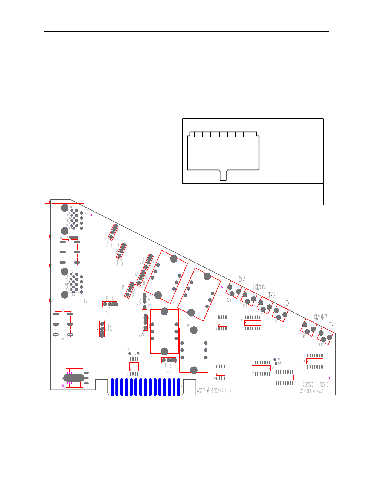
Figure 5 Line Card layout............................................................................................................................... 8
Figure 6 Crossmute Diagram.......................................................................................................................... 9
Page 7

Remote Control Console 1
1 Introduction
The model C-1616 is a unique multi-channel, multi-format, and self-contained desktop radio control console.
The C-1616 sports a Vacuum Florescent LCD display, which provides channel alpha/numeric indication, clock and
audio-level meter with a modern membrane keypad. These features allows for a more flexible dispatch environment
in which the console may be installed. The dispatcher can easily operate the console while sitting or standing.
The C-1616 is a Digital Signal Processor (DSP) based design, allowing easy field programmability using the DTMF
keypad on the front of the console. Unlike other manufacturers’ equipment, no additional software is required to
program the C-1616 console. Modifications and enhancements can generally be made via a software change only. If
the user determines they require a special feature enhancement, please contact the Vega Sales Department for cost
and feasibility.
The C-1616’s modular design offers selection and control of up to six base stations, along with selection of sixteen
frequencies. The base configuration includes one line card, allowing 2 lines of control. Each line card consists of two
independent channels that offer crossmute capability and squelch control features eliminating the unwanted noise
that is generally associated when monitoring a selected or unselected line.
The C-1616 will accommodate a desk microphone (or gooseneck microphone) along with a handset (or headset) as
indicated on the side of the C-1616 console. When a PTT occurs from either of the two microphones, the other will
mute so as not to pick-up unnecessary ambient noise during transmission. When the handset is taken off hook and a
line is Selected, the receive audio from that line is transferred to the earpiece.
The console is normally used in conjunction with up to six functionally matching Vega DSP223 or TRA223 Series
(or equivalent) tone-remote panels located at each base station. The console is compatible with Motorola, ComNet
Ericsson/GE, and other tone-remote control systems employing the industry-standard sequential tone-control format.
The console is connected to the mating panels by means of voice-grade or better leased or private lines (including
microwave circuits). Metallic or DC continuity is not required.
Page 8

2 Vega’s C1616
2 Hardware Overview
The C-1616 is a multi-line; multi-mode console designed specifically for medium level system requirements. All
functions are housed in a single small modern looking console.
2.1 C-1616 Console
The C-1616 consists of the following sub-assemblies enclosed in the single case: Main Processing Board, Line
Interface Cards, Keypad/Display Board, and speaker amplifier.
2.1.1 Main PCB
The Main PCB is mounted to the bottom of the enclosure using 5 #6 screws. It contains the DSP that handles all
audio processing and user interface features. Three two channel Digital to Analog Converters (DAC’s) are utilized
to generate audio for transmission, recordings, auxiliary speaker, main speaker, earpiece, and keyboard feedback.
One two channel Analog to Digital Converter (ADC) is resident on the main board which digitizes both the
microphone inputs and the auxiliary audio inputs. Each line card contains an ADC as well for the two lines of audio
supported on the card. Three 30-pin card slots reside on the main board for each optional line card. A 20-pin header
is used to interface the keypad to the Main Board. All audio detection, generation, and filtering are performed within
the DSP. Two potentiometers are available for adjusting the handset and desk microphone input levels. A three-pin
header is supplied on the main board that connects to the unselect audio control potentiometer.
2.1.2 Keypad PCB
The Keypad board is interfaced to the main board via a 20-pin ribbon cable. The board contains the circuitry to
drive the 45 LED’s, decode the keypad matrix, and interface the DSP to the display. The display itself is mounted to
the Keypad PCB by a 14-pin header and three screws with spacers.
2.1.3 Line Card
The Line Card is a radio control card using either the standard tone control format compatible with Motorola and
M/A-Com/ComNet Ericsson/GE or Local Control relay closure. The line card may be hardware configured for either
two or four-wire operation and may be factory modified to accommodate non-industry standard tone control formats
if desired. This is usually a software only change. Each card supports two lines and has six potentiometers mounted
on the card to support tuning of the Receive, Transmit and Transmit monitor levels.
2.1.4 Internal Speaker Amplifier
The internal speaker has a 5-watt amplifier mounted on the backside of the front cover. Which has one volume
control input to which the “Select” volume control is connected. A jumper is used for setting a minimum output
level, allowing for audio at some level always being present in the internal speaker.
Page 9
Remote Control Console 3
UNSEL
GRP
TXALL
SUP MUTE
RXALL
ALERT
MON IC LN4 LN5 LN6 LN1 LN2 LN3 F1
F3 F5
F2 F4 F6
F7 F9 F8
F10
SELECT UNSELECT
11:08AM
Adam 12
Unselect Audio LED
Line Audio Monitor
Program 1
-4
Transmit LED
DTMF Keypad
20
-
5 0 +3dB
F16
F15 F11
F12 F14
F13
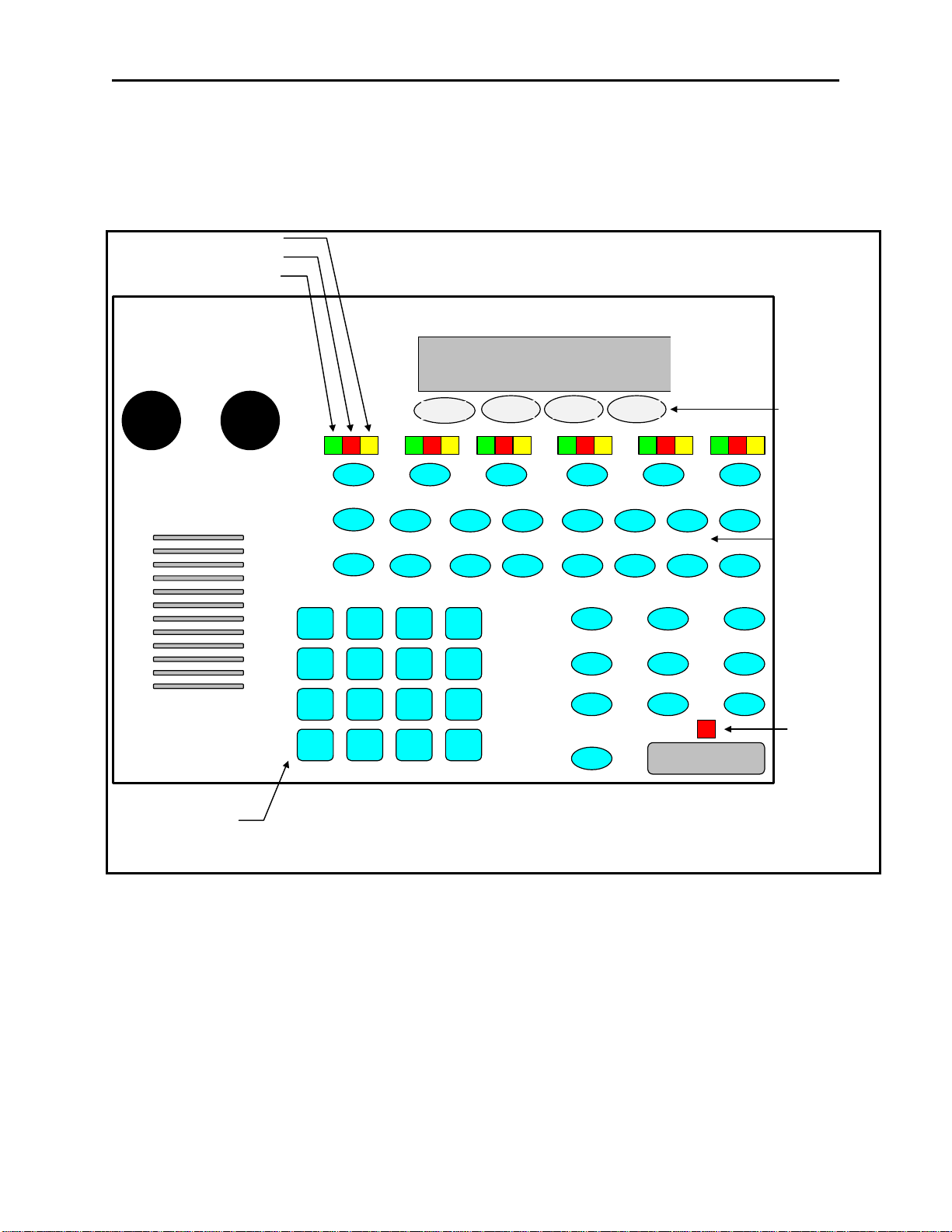
3 Controls and Indicators
3.1 Front Panel
Description of the controls and indicators.
Select Audio LED
Audio Level-
VOLUME
1
A B
4
G H
7
M N
*
S T
2
C D
5
I J
8
O P
0
U V
PROG 1
3
E F
6
K L
9
Q R
#
W X
PROG 2 PROG 3
A
+ -
B
.
C
CAP
D
Y Z
Figure 1 Front Panel view
PROG 4
Function Tone
Select Keys
TRANSMIT
A desk microphone (or gooseneck microphone) may be installed for operation along with a handset (or headset) as
indicated on the side of the C-1616. When a PTT occurs from either of the two microphones, the other will mute so
as not to pick-up unnecessary ambient noise during transmission. Note that, in dual microphone configurations, the
desk microphone is the default microphone. The dedicated PTT button on the handset or headset must be pressed to
use the handset/headset.
3.1.1 Common Controls and Indicators
Select Volume Control: Adjusts the summed speaker level of the Selected and Unselect audio’s. A minimum
volume level can be set on the speaker card so that the console operator cannot turn the volume to zero.
Unselect Volume Control: Adjusts the speaker level of the Unselected audio. A minimum volume level is preset on
the main PCB so that the console operator cannot turn the volume off as long as the master minimum volume is
active on the speaker amplifier (JP1). Refer to page 11 for more detailed information.
Page 10

4 Vega’s C1616
Optional Handset: When you come off hook the handset receive audio is transferred to the earpiece and the
microphone mouthpiece becomes active. Unselect audio that is being routed to the external speaker will not be
affected.
VU Meter: Displays Selected receive and Microphone audio bus levels. This meter is shown on the top line of the
display and utilizes the first 12 display elements from the upper left.
PTT Pushbutton: When pressed all Selected lines will transmit from the default input device (handset, headset, desk
microphone, gooseneck)
DTMF Keypad: The DTMF keypad is used for transmitting DTMF digits, selecting frequencies for tone control in
tech mode (section 6), and entering alphanumeric strings for line/function tone combinations.
Function Buttons F1-F16: When a function tone button is pressed, a guard tone and function tone burst is sent out.
No hold tone is associated with the changing of the function tone. When one of the function tones is selected it will
light to indicate which function tone is chosen. A function tone shall remain selected until the operator changes the
setting. The console will power up with the last selected line and function tone pair selected. Function tones may
also be placed in wildcard groups (section 6.3.3.2), wildcard groups will not effect any function tones in the
frequency selection mode.
Line Select Buttons LN1-LN6: Six line select buttons are available. When one of the line buttons is pressed that
line enters the Select mode and cancels all other Selected lines (either inactive or Unselected). The ‘1 of N’ mode
can be changed by pressing the GRP button ONn, this allows more than one line to be placed in the Select mode. A
line or lines can be placed in the Unselect mode by the pressing the UNSEL button on and then pressing the Select
line button. You may have any combination of lines placed in the Unselect mode.
Program 1-4: Are used as “soft” programming buttons when in the tech mode. These buttons will have different
functions depending on the action required. The bottom line of the display will show their respective functions.
Select Audio LED: The green LED above each LNx Button indicates if the line is selected for transmit audio.
Unselect Audio LED: The red LED above each LNx Button indicates if the line is unselected for receive audio
monitoring.
Line Audio Monitor LED: The yellow LED above each LNx Button indicates receive audio activity on a line.
Transmit LED: This LED lights when any PTT source is depressed keying up the console. It will also blink if a
2175 Hz hold tone is detected on the selected TX audio lines. This would indicate to the operator that another
console is currently transmitting on one of the selected channels.
Unselect button: Pressing the line buttons while the UNSEL button is on will place the respective lines in Unselect
mode. Pressing a line that is already in the Unselect mode will deselect the line. Pressing a line that is already in the
Select mode will have no affect.
Group button: The 1of N reset function of the C-1616 will be suspended while the GRP button is on. This allows
the operator to place more than one line in Select mode. The C-1616 allows four preprogrammed groups. These
preprogrammed groups will be applied to the console if the ‘A’, ‘B’, ‘C’, or ‘D’ in the DTMF keypad is pressed
while the GRP button is held down. A programming selection allows the technician to apply a preprogrammed
function tone or the last used function tone to the group.
TX all button: The TX button allows the operator to place all lines in the Select mode. A programming selection
allows the technician to apply a preprogrammed function tone or the last used function tone to the group.
RX all button: The RX button places all cards not in the Select mode in the Unselect mode.
Supervisory button: The SUP button allows one console operator to disable any other console which is connected
to the supervised line.
Monitor: When the Monitor button is pressed a Monitor tone burst is sent out. The Monitor tone burst consists of a
guard tone and function tone of 2050Hz. An LED indication lights for the duration of the tone burst.
Intercom (IC): When the Intercom button is pressed and held down the C-1616 shall transmit audio without
activating the tone generator. Intercom is considered a PTT operation with the tone generator disabled.
Page 11
Remote Control Console 5
AUD
+ -
3.2 Rear Panel Connections
+12
Power
Figure 2 Rear Panel View
AUX
Power
+ GND E
Line 1
Line 2
1
8
Line 3
1
8
Line 4
AUX
RELAY
OUT
1
8
1
8
FOOT
SWITCH
AUX
SPEAK
Line 5
Line 6
RECORD
OUT
1
8
1
8
AUX INRS-232
PTT GNDSW GND
3.2.1 Rear Panel Ports
Line Ports 1-6: The C-1616 can accommodate up to six-lines, in multiples of two. The six-line connectors are
available on the rear of the unit. The connectors are standard eight pin RJ-45 connectors. The pin out of the
connector appears in Figure 3. The numbering of the pins are shown in Figure 2 for reference.
Auxiliary Audio Input: The external 3 pin terminal block provides Audio Input, PTT, and GND line. Pulling PTT
to ground activates the Audio Input line for transmitting. This input is a high impedance capacitance coupled input.
Auxiliary Speaker: Is a capacitance-coupled output capable of driving a 600-ohm load at 0dbm.
Footswitch: This input acts as a console PTT when it is shorted to ground
Battery backup: The Auxiliary power input is a diode-protected +12V input used for battery backup. Pin (E) is
also connected to the chassis allowing for positive grounding of the unit.
Serial port: Allows for communications between consoles. Normally used when cloning other consoles.
Auxiliary Relay Output: Depending on the setting of the AUX button in the tech mode, this output is a relay
closure that can be used for whatever purpose is required.
Record Output: Has both unselected and selected notched audio 600-Ohm transformer output for connection to a
voice-logging recorder.
Page 12

6 Vega’s C1616
4 Functional Description
4.1 Grouping Options
4.1.1 Basic Line/Function Tone Operation
The basic operating scenario would be a single line and function tone selected. Lines can be selected individually by
pressing any LN1-LN6 and function tone button F1-F16. Upon keying the microphone, a high level guard tone
followed the selected function tone is sent out, the low level guard tone is then transmitted along with the
microphone audio. Each Line/Function pair is unique and can have its’ own alphanumeric characters assigned to it
in the programming mode. The default characters have the LnX FY label in the display with X the line number and
Y the function number. Function Buttons can have either single or dual functions and is setup in the tech mode.
4.1.2 GRP and TX ALL Buttons
The GRP button is a press ON/OFF button that disables the 1of N functionality of the console. When the GRPSEL
button is selected it will illuminated and the operator can set up a Simul-group with as many tone lines desired. As
long as the button is illuminated the operator may add or delete lines in the group. The Green LED above each line
selection button denotes that the line is selected for transmission and reception. When the operator is finished setting
up the Simul-group the operator presses the GRP button again to revert back to the 1of N mode.
The group button is also used to select up to four preprogrammed groups. Within the tech mode, it is possible to set
up preprogrammed groups. By assigning certain groupings of lines to the Groups ‘A’-‘D’ a simple two button
sequence can be setup to select multiple lines.
Note: Lines that are setup as Local Control cannot be mixed with tone control lines in the same group select mode.
Likewise you cannot TX ALL if you have Local control and tone control lines mixed. You will receive an ERROR
MESSAGE. They must all be of the same type of control lines tone or local control.
TX ALL (Transmit All): This feature gives the user a convenient means of Selecting all lines for Simultransmissions without having to group select one at a time.
To initiate Simulcast, momentarily touch the "TX ALL" on the keyboard. The line description will change to
"Group", and all available lines will automatically be Selected.
To disengage Simulcast, simply Select a single line in the usual manner, or press TX again to revert to the previous
setup.
Note: You cannot TX ALL if you have Local control and tone control lines mixed. You will receive an ERROR
MESSAGE. They must all be of the same type of control lines tone or local control.
4.1.3 UNSEL and RX ALL Buttons
The UNSEL Button functions the same way as the GRP button. The UNSEL button is a press ON/OFF button.
When the GRPSEL button is illuminated the operator is able to set up any combination of lines as desired for
monitoring only. As long as the button is illuminated the operator may add or delete lines to the group. The red
LED above each line selection button denotes that the line is Unselected for reception. When the operator is finished
setting up the group the operator presses the UNSEL button again to turn off the mode.
RX ALL (Receive All): When pressed all lines are put into the unselect receive mode. Any line that is in the Select
mode will automatically become part of the Unselect group when it is taken out of Select mode.
Page 13
Remote Control Console 7
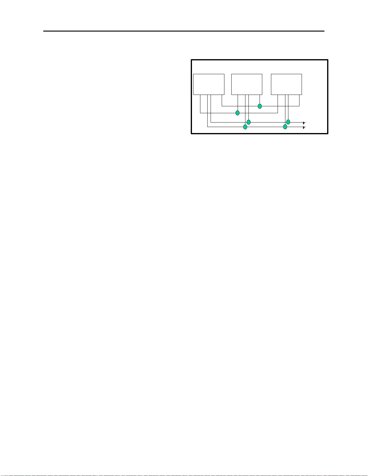
4.2 Other Control Buttons
4.2.1 Supervisor Button
The SUP Button is used to disable all units on a particular
line. Its connection is similar to that of the crossmute
function. Tech mode is utilized to determine which
consoles will have supervisory capability. It is possible to
setup only specific consoles with this feature. If a console
has the feature enabled, by pressing the SUP Button, the
Button will light and disable all connected paralleled
consoles. On the consoles that are being supervised, the
SUP Button will blink, if they have selected a line that the
supervisor has selected. Figure 3 shows the connection
scheme required to utilize this function. Pin 2 of all
consoles are connected together. In addition, Pin 8 is also
connected together on all consoles, serving as a common
ground for all consoles. Assuming that console 1 has
supervisory capability, when activated, Line 1 on parallel consoles 2 and 3 would then be inhibited.
4.2.2 MUTE Button
The MUTE Button is used to mute unselect audio. It is programmable in tech mode to be a mute when pressed, or
mute for a programmable period of time. As long as MUTE is active, the Button will be lit up.
Console 1: Console 2: Console 3:
Line 1
1 2 3 4 5 6 7 8 1 2 3 4 5 6 7 8 1 2 3 4 5 6 7 8
Figure 3 Supervisory Diagram
Line 1 Line 1
Line Line +
4.2.3 AUX Button
The AUX Button has up to four functions, selectable in tech mode:
1) DTMF store and transmit DTMF
2) Second Alert tone ALERT
3) Toggle relay control TOGGLE RELAY
4) Momentary relay control MOM RELAY
Option 1, DTMF store and transmit, allows a programmed string of DTMF characters to be entered and transmitted.
In addition, the function will remember the last string sent and can be recalled by pressing a Program Button.
Option 2, ALERT, allows the AUX Button to serve as the Alert 2 Button. In this mode it sends out the programmed
Alert 2 tone.
Option 3, Toggle Relay, give the AUX button the ability to control the AUX RELAY output on the back panel.
When pressed, the Button will light and the relay will close. The next time the AUX button is pressed, the Button’s
light will turn off and the relay will open. The relay is rated to handle 500mA at 12VDC or 250mA at 115VAC.
Option 4, Momentary Relay, closes the relay for as long as the AUX button is pressed. The relay is rated to handle
500mA at 12VDC or 250mA at 115VAC.
4.2.4 Alert Button
The Alert Button is used to send the programmed Alert sequence. Tech mode is used to set up the cadence assigned
to this Button.
4.2.5 Intercom (IC) Button
When the IC button is pressed and held down the C-1616 transmits audio without activating the tone generator.
Intercom is a PTT operation with the tone generator disabled. This is useful for communications between paralleled
consoles.
Page 14
8 Vega’s C1616
1 2 3 4 5 6 7 8
Figure
5 Line Card Setup and Description
5.1 INTRODUCTION/DEFAULTS
The Line Card for the C-1616 system provides communication with any standard tone remote system. It is shipped
from the factory in the following state:
4 Wire mode with 600 ohm Input and Output impedance
5.2 INPUT/OUTPUT
Two Line connectors are available for external access.
The connectors are standard eight pin RJ-45
connectors. The upper connector on each card is
designated as 1 and the lower as 2. The slot that the
card is placed in designates line 1&2 or 3&4 or 5&6.
Two six-foot cables are included with each card. The
connector pins are assigned as shown in Figure 3.
Figure 3 Line Jack pin out
4 Line Jack Pin-out
1) Cross Mute I/O
2) Supervisor I/O
3) RX +
4) TX +/ (RX + 2W)
5) TX -/ (RX - 2W)
6) RX -
7) Local
8) GND/Local
Connector View
Figure 5 Line Card layout
Page 15
Remote Control Console 9
TX +
TX -
RX
RX -
5.3 FEATURE DESCRIPTION
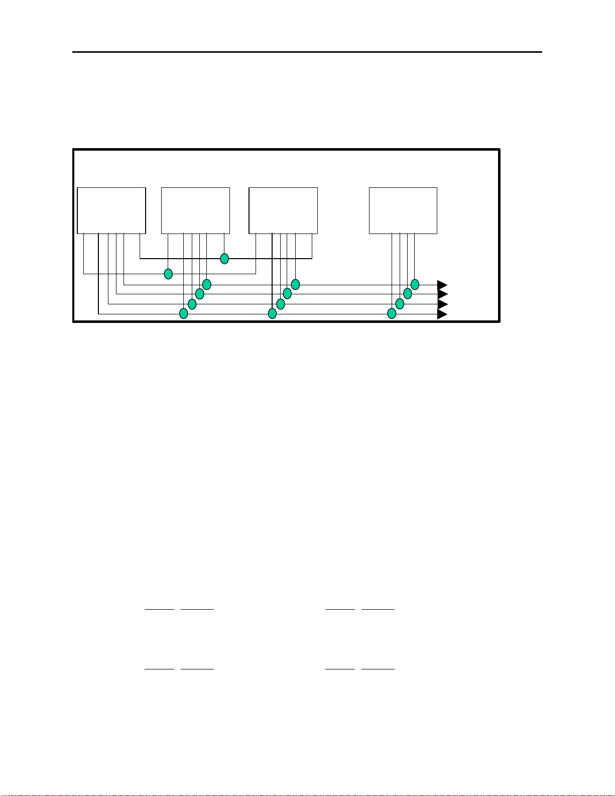
5.3.1 Crossmute
When a parallel console operator keys a microphone in the same room, the crossmute function will mute the receive
audio path of other parallel consoles. This prevents any unwanted audio loops which would occur causing a loud
squeal on the paralleled speakers.
Console 1: Console 2: Console 3:
Line 1
1 2 3 4 5 6 7 8 1 2 3 4 5 6 7 8 1 2 3 4 5 6 7 8 1 2 3 4 5 6 7 8
Figure 6 Crossmute Diagram
Feedback may be avoided by muting the receive audio of the line card which is in parallel with a transmitting line
card. This may be accomplished by connecting pins 1 and 8 of each of the consoles to be crossmuted as shown in
Figure 7. Pin 8 must be connected to provide a common ground. Figure 5 illustrates the connections between
consoles 1 through 3 that are in the same room and when one transmits, the receive audio on line 1 will be muted.
Console 4 is off-site with no possibility of feedback, therefore, it is not being muted.
Note: The intercom function will not work between crossmuted consoles.
Offsite
Console 4:
Line 1 Line 1 Line 1
5.3.2 Relay Contact Closure For Local Control
The relay is normally open and provides a dry contact closure during PTT functions between pins 7 and 8 of the line
jack. The relay closure can carry 500mA at 12VDC or 250mA at 115VAC. When using the intercom function the
relay is not activated.. If this relay closure is used for local control (or any other case where tone bursts are not used
for signaling) disabling the tone generation is recommended by entering the tech mode.
5.3.3 Two-Wire/Four-Wire Mode
Each Line Card comes standard with a jumper selectable two or four-wire option. Note: The Line Cards are shipped
in the four-wire mode. Two-wire mode is accomplished by the following jumper positions:
Line 1, 3, 5: Line 2, 4, 6:
Two-Wire: Jumper Position Jumper Position
JP12 A JP10 A
JP13 A JP11 A
Four-Wire: Jumper Position Jumper Position
JP12 B JP10 B
JP13 B JP11 B
The RX pair is now on pins 3 and 6 on the connector and the TX pair is on pins 4 and 5. Once transmit and receive
paths are separated the impedance of each side must be set.
Page 16

10 Vega’s C1616
5.3.3.1 RX Side Settings
For 4-wire lines the RX side is jumper selectable for either 600 or 10k ohm impedance. If only one Line Card is on
the line (no parallel consoles) then place J9 (Line 1,3,5) or J8 (Line 2,4,6) in the A position for a 600-ohm line
impedance. If more than one Line Card is on one line then place J9 (Line 1,3,5) or J8 (Line 2,4,6) on ONE console
in the A position and all other consoles in the B position. Each console added to the system will result in line loss.
The following chart gives an indication as to how much loss can be expected. The first console in the system is set
for an impedance of 600 ohms out (approximately). Each console added to the system thereafter is set for an
impedance of 10k ohms. As the chart indicates on the following page, the more consoles bridged on the line, the
lower the line impedance and the greater the loss in audio level.
Console added Position Impedance Impedance Loss (dB)
1 A 604 604 0.0
2 B 10k 569 -0.5
3 B 10k 539 -1.0
4 B 10k 511 -1.5
5 B 10k 486 -1.9
6 B 10k 464 -2.3
For 2-wire lines always place J9 and J8 in the “B” position.
Level adjustment can be made to the receive audio by adjusting the Line RX IN, see section (5.4.1.3).
5.3.3.2 TX Side Settings
Two jumpers on the transmit pair allow a degree of control over the output impedance. The following chart lists the
jumper positions for each card depending on how many consoles are placed in parallel. All cards should have the
same jumper settings.
Consoles in parallel Individual TLM Output Impedance (per console)
Line 1,3, 5: J4 J5 Line 2, 4, 6: J6 J7
1 (one console on line) A A A A 600 ohms
2 B A B A 1200 ohms
3 A B A B 1800 ohms
4 B B B B 2400 ohms
The TX levels can be set by potentiometer on a per line basis. Refer to section 5.4 level adjustments for setup
procedures.
5.3.3.3 Transmit Monitor
In a four-wire system the transmit line may be monitored by the receive circuits by changing a setting in tech mode.
Refer to section 5.4.1.2. for the monitor level setup adjustment. The transmit monitor is not needed in two-wire
mode as the transmit audio is already on the receive circuit.
5.4 Level Adjustments
Figure 4 in this section, shows a top view of the Line Card with the adjustment points labeled. The potentiometers
are available without taking the card out of the chassis.
5.4.1 Transmit Side Adjustments
The transmit audio consists of multiple audio sources – microphone audio, AUX input, function tones, and DTMF
tones. Each audio sources is summed or generated in the DSP with the analog signal being generated on a single
DAC. The following is a list of the potentiometers that affect the transmit path.
Line1, 3, 5: Line2. 4, 6:
Reference Description Reference Description
R41 Line 1 TX Level Adjustment R42 Line 2 TX Level Adjustment
R40 Line 1 TX Monitor Level Adjustment R39 Line 2 TX Monitor Level ADJ.
R21 Line 1 RX Level Adjustment R20 Line 2 RX Level Adjustment
Page 17

Remote Control Console 11
5.4.1.1 Transmit Level Setup
The transmit level potentiometers are used to adjust the output levels of the transmit audio so that it is calibrated with
the onscreen level sets found in the tech mode. Calibration of the Transmit lines will vary depending on system
variables as well as the number of consoles found in parallel on the line. The tech mode can be used to generate a
test tone at a given amplitude. R41 and R42 should then be adjusted with a level meter used to set the actual output
level to match the generated value.
5.4.1.2 Transmit Monitor Setup
The transmit monitor provides a portion of the transmit audio of a four-wire circuit to the receive path. This allows
the console operator to listen to the transmissions of parallel console operators. To set this level have a parallel
console operator select a line and press the intercom button. Adjust R40 and R39 on each four-wire circuit until the
level is comfortable in the handset/headset earpiece or the speaker.
5.4.1.3 Receive Level Setup
The receive side level potentiometers are used to adjust the input levels into a range that is acceptable to the C-1616.
Typically, a +10dBm test tone is injected in to the C-1616 as receive audio. The audio level is then measured at TP2
for Line 1 and TP1 for Line 2 with respect to ground. The measurement should be about 3.4 Vpp or 1.2Vrms.
However, if receive audio levels are not in the +10dBm range, these pots can be used to bring the audio level up to
the desired receive levels. 3.4Vpp is about the maximum value for the loudest receive audio. Above 3.4Vpp will
saturate the ADC input stage and distortion will occur.
5.5. Microphone Level Adjustment
Adjusting handset/headset microphone levels. Make a vocal tone into the handset while adjusting R72 on the Main
PCB for 3.5Vp-p at TP2. The sidetone cannot be adjusted, speak into the handset and listen to the earpiece. You
should hear a portion of your voice being routed back to the earpiece.
Adjusting desk microphone/gooseneck microphone levels. Make a vocal tone into the desk microphone/gooseneck
microphone at the distance you expect the operator to be positioned and adjust R71 on the Main PCB for 3.5Vp-p at
TP7.
5.6. Minimum Speaker Level Adjustment
A minimum volume level can be set by moving JP1 to “B” position on the speaker Amplifier PCB, preventing the
operator completely turning off the volume of the speaker.
Page 18

12 Vega’s C1616
YES NO
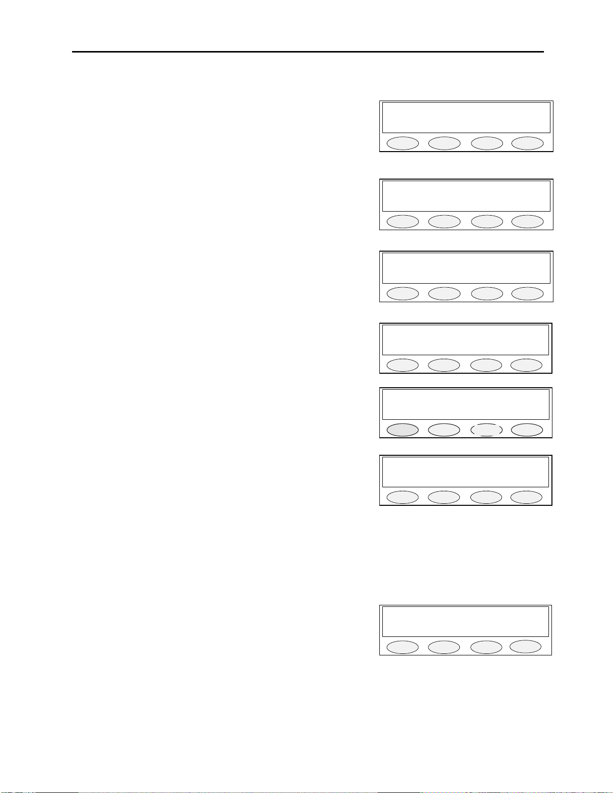
6 Tech Mode
The tech mode allows a technician to program the internal settings of the C-1616 console.
The tech mode is entered by pressing MUTE - F6 - *(star) simultaneously. The technician may be required to
enter a PIN number to allow entry. See the section 6.3.4.1 on setting up the PIN number. The Opening Menu is
displayed when tech mode is entered. In addition to the information on the display you will visual see the MOM,
LN1-LN6, ALERT, AUX, F1-F16, GRP and the MUTE buttons also flash indicating you are in the tech mode of
operation. These buttons also provide setup options when pressed, refer to section 6.0.4. for further information.
6.0.1 Erasing all settings
All of the settings in the console can be reset to factory defaults by pressing and holding both “IC” and “*” and then
applying power. The screen displayed asks if the user wants to restore defaults or not.
PROG1 - Answer, YES and you will clear all settings to the factory
defaults.
PROG3 - Answer, NO and you will enter the user mode.
6.0.2 Resetting the PIN Number
In the event the PIN number is either forgotten or not known, the test jumper J17 on the main board inside the unit
can be used to enter a self test mode and reset the PIN. With the power removed from the unit, move J17 to the “B”
position on the board. Power up the board. The PIN number is cleared allowing immediate entry into the tech
mode. Power down the board and move the J17 back to the “A” position. Close the case and resume normal
operations with the C-1616.
Restore Defaults?
PROG1 PROG2 PROG3 PROG4
Page 19

Remote Control Console 13
6.0.3 Opening Display Menu
|----------Level menu Screen
| |----------Line Level Settings (Select LEDS Blink)
| | |----------RX Input Level
| | |----------Other Line Levels
| | | |----------LAM Programming
| | | | |----------LAM duration after release
| | | | |----------Trigger Level
| | | | |----------Select/Unselect Settings
| |----------Main Level Settings
| | |----------Microphones
| | | |----------Desk microphone preamp gain
| | | |----------Handset preamp gain
| | | |----------Aux input preamp gain
| | |----------Receive Path Levels
| | | |----------Handset Earpiece Level
| | | |----------Auxiliary Speaker Output Level
| | |----------TX Menu
| | | |----------TX Audio Output Level
| | | |----------Tape Output Level Control
|----------System Settings Screen
| |----------Menu 1
| | |----------Clock
| | |----------Dump (RS-232C clone command)
| | | |----------Dump Error Screen
| |----------Menu 2
| | |----------Tone Settings
| | | |----------DTMF Settings
| | | | |----------DTMF Output Level
| | | | |----------Tone duration
| | | | |----------Tone Spacing
| | | | |----------Hang Time
| | | | |----------Keypad Enable/Disable
| | | | |----------PTT with DTMF Enable/Disable
| | | | |----------Incoming Select Call Setup
| | | | |----------Select Call Timer Setup
| | | |----------Single Tone Settings
| | | | |----------Guard/Function/Hold Levels
| | | | |----------Guard/Hold Frequencies
| | | | |----------Guard/Hold duration’s
| | | |----------Test Settings
| | | | |----------Alert Tone Test
| | | | |----------Tone 1
| | | | |----------Tone 2
| | |----------Wildcard programming
| |----------Menu 3
| | |----------Tech mode PIN Number
| | |----------TX Delay setup
| |----------Menu 4
| | |----------Aux Relay Function
| | |----------Duplex
| |----------Menu 5
| | |----------MicAGC Enable/Disable
| | |----------Handset Connected
|----------Alphanumeric Decision Screen
|----------Line/FTone Selection screen (Blinking Line Select LED)
| |----------Line Alphanumeric Selection screen
| | |----------Line Alphanumeric Programming Screen
|----------Group Selection Screen (Blinking GRP Button)
|----------Group Alphanumeric Selection screen
|----------Group Alphanumeric Programming Screen
Page 20
14 Vega’s C1616
LVLS SYS ALPHA EXIT
Main back
6.0.4 Button Activated Setup Modes
|----------LN1-LN6 - Per Line Parameters Setup
| |----------Line Enable/Disable
| |----------Tone/Local Setting
| |----------Crossmute Enable/Disable
| |----------Squelch
| |----------TX Monitor Enable/Disable
| |----------AGC
| |----------TX Enable/Disable
| |----------Unselect Normal/Locked
|----------F1-F16 - Function Tone Parameter Screen
| |----------Function Tone Enable/Disable
| |----------Tone Programming Screen
| | |-----------Tone A/B Selection
| | |-----------Frequency Programming Screen
| | |-----------Duration Programming Screen
|----------UNSEL Unselect Audio Setup
| |---------- Audio Routing Selection Internal/External
| |---------- Audio Muting on PTT
|----------GRP - Group Assignments A-D
|----------SUP - Supervisor Function Enable/Disable
|----------MUTE - Mute Button Setup
| |----------Timed/Momentary
| |----------Timed Mute Duration Setup
|----------AUX - AUX Assignment
|----------ALERT - Alert Cadence Programming
| |----------Frequency and Levels
|----------TX ALL - Enable/Disable Parameter Screen
|----------MON - Monitor Programming Screen
|----------Auto/Manual Selection
|----------Monitor Tone Selection
|----------Monitor Frequency
|----------Monitor Duration
|----------Monitor Level
6.1 Opening menu
The following buttons are active during this screen:
PROG1 - Pressing this button enters the Level Menu Screen
PROG2 - Directs the display to the System Settings Screen
PROG3 - Directs the display to the Alpha Settings Screen
PROG4 - Exits the Setup Mode
LN1-LN6 - Directs the display to the Line Tone/Local Screen
F1-F10 - Function Tone Parameter Screen
UNSEL - Controls Unselect Audio routing to internal/external
GRP - Enters the group setup mode
SUP - Enables supervisor mode
MUTE - Set mute functionality
AUX - Directs the display to the AUX Assignment Screen
ALERT - Directs the display to the Alert Cadence Programming Screen
MON - Directs the display to the Monitor Programming Screen
TX ALL - Allows the TX ALL button to be enabled and disabled
6.2 Level Menu Screen
When this screen is displayed the following buttons are active:
PROG1 - Direct display to Main Level Settings Screen
PROG4 - Go back to Opening Menu
Pressing any Line button - Displays the Line Level Setting Screen for that
selected line.
PROGRAMMING MODE
PROG1 PROG2 PROG3 PROG4
Select Line/Main
PROG1 PROG2 PROG3 PROG4
Page 21
Remote Control Console 15
RX LAM back
0dBm
dwn up back
dur
lvl S/U back
7sec
dwn up back
-20dB
dwn up back
Main level adjust
MIC RX TX back
Main
desk hand
aux back
6.2.1 Menu 1 - Line Level Settings
This screen is displayed after a line has been selected from the Level Menu Screen. The selected line number is
shown on the display and the select LED for that line continues to blink. In this example Line 1 has been selected.
PROG1 - Go to RX Input Level Screen
PROG2 - Go to LAM level setup
PROG3 - Go to Line Levels Screen
PROG4 - Return to Level Menu Screen
Line 1 level adjust
PROG1 PROG2 PROG3 PROG4
6.2.1.1 RX Input Level Screen
The RX output levels serve as a master level adjustment allowing small adjustments in gain. This is a per line
adjustment. Typically these are left at 0 dB.
Line 1 Rx lvl 0dBm
PROG1 - Resets level setting to default of 0dB
PROG2 - Increments the level setting by 1 dBm (max of +30dB)
PROG3 - Decrements the level setting by 1 dBm (min of -50dB)
PROG4 - Saves the current level setting and returns to the Line Level
Setting screen
6.2.1.2 LAM Programming Screen
This screen shows the current settings for the Line Activity Monitor for the line number shown. The -U or -S after
the channel number denotes whether the settings are for Select or Unselect Audio. Pressing PROG1 or PROG2 will
modify the settings for the Select or Unselect characteristics displayed when the button is pressed.
PROG1 - go to LAM Duration After Release screen
PROG2 - go to LAM Trigger Level Screen
PROG3 - Toggle Select or Unselect LAM control
PROG4 - return to Other Line Level Screen
PROG1 PROG2 PROG3 PROG4
LAM 1-S 0sec 0dBm
PROG1 PROG2 PROG3 PROG4
6.2.1.2.1 LAM Duration After Release screen
This parameter determines how long the LAM light will flash after the triggering signal disappears.
PROG1 - Resets duration setting to default of 7 seconds
PROG2 - Increments the time setting by 1 second (maximum of 25sec)
PROG3 - Decrements the time setting by 1 second (minimum of 0sec)
PROG4 - Saves the current duration setting and returns to the LAM
Programming Screen
6.2.1.2.2 LAM Trigger Level Screen
This parameter determines the audio level required to trigger the LAM function.
PROG1 - Adjusts level at which the LAM triggers
PROG2 - Increments the level setting by 1 dBm (max of 0dBm)
PROG3 - Decrements the level setting by 1 dBm (min of -30dBm)
PROG4 - Saves the current level setting and returns to the LAM
Programming Screen
LAM 1-S Dur 0sec
PROG1 PROG2 PROG3 PROG4
LAM 1-U Level -20dBm
PROG1 PROG2 PROG3 PROG4
6.2.2 Main Level Settings
PROG1 - Go to Microphones Screen
PROG2 - Go to Receive Path Level Screen
PROG3 - Go to the Transmit Level Screen
PROG4 - Return to Opening Menu
PROG1 PROG2 PROG3 PROG4
6.2.2.1 Microphones Screen
PROG1 - Go to Desk microphone Preamp Gain Screen
PROG2 - Go to Handset Preamp Gain Screen
PROG3 - Go to the aux input levels screen
PROG4 - Return to Main Level Settings screen
PROG1 PROG2 PROG3 PROG4
Mic adjust
Page 22
16 Vega’s C1616
0dB
dwn up back
0dB
dwn up back
Aux-in level: 0dB
0dB
dwn up back
Main RX adjust
hand
Aux back
0dB dwn up back
Aux Speaker 14dB
20dB
dwn up back
0dBm dwn up back
6.2.2.1.1 Desk microphone Preamp Gain Screen
The current setting is shown in the upper right hand corner of the screen. This setting is for the pre-amp level of the
deskmic.
PROG1 - Resets level setting to default of +0dB
PROG2 - Increments the level setting by 1 dB (maximum of +10dB)
PROG3 - Decrements the level setting by 1 dB (minimum of -10dB)
PROG4 - Saves the current level setting and returns to the
Microphones screen
Deskmic level 45dB
PROG1 PROG2 PROG3 PROG4
6.2.2.1.2 Handset Preamp Gain Screen
PROG1 - Resets level setting to default of +0dB
PROG2 - Increments the level setting by 1 dB (max of +10dB)
PROG3 - Decrements the level setting by 1 dB (min of -10dB)
PROG4 - Saves the current level setting and returns to the
6.2.2.1.3 Aux Preamp Gain Screen
PROG1 - Resets level setting to default of +0dB
PROG2 - Increments the level setting by 1 dB (max of +10dB)
PROG3 - Decrements the level setting by 1 dB (min of -10dB)
PROG4 - Saves the current level setting and returns to the
6.2.2.2 Receive Path Levels
PROG1 - Go to Desk microphone Preamp Gain Screen
PROG2 - Go to Handset Preamp Gain Screen
PROG4 - Return to Main Level Settings screen
6.2.2.2.1 Handset Earpiece Level
PROG1 - Resets level setting to default of +0dB
PROG2 - Increments the level setting by 1 dB (maximum of +10dB)
PROG3 - Decrements the level setting by 1 dB (minimum of -10dB)
PROG4 - Saves the current level setting and returns to the Receive
6.2.2.2.2 Aux Speaker Output Level
PROG1 - Resets level setting to default of +0dB
PROG2 - Increments the level setting by 1 dB (maximum of +10dB)
PROG3 - Decrements the level setting by 1 dB (minimum of -10dB)
PROG4 - Saves the current level setting and returns to the Receive
Handset level 0dB
PROG1 PROG2 PROG3 PROG4
PROG1 PROG2 PROG3 PROG4
PROG1 PROG2
Handset RX 0dB
PROG1 PROG2 PROG3 PROG4
PROG1 PROG2 PROG3 PROG4
PROG3
PROG4
6.2.2.3 Output Level Screens
Entering the TX output level screen allows for setting two options for output levels. The first is for the audio TX
level, and the second is for the Tape output level.
6.2.2.3.1 TX Output Level
The TX output level is adjusted as shown on the display. This is an overall output gain control for the line. It can be
used to make small adjustments to the line level performance. The typical value is 0 dB.
PROG1 - Resets level setting to default of 0dBm
PROG2 - Increments the level setting by 1 dBm (max of +10dBm)
PROG3 - Decrements the level setting by 1 dBm (min of -10dBm)
PROG4 - Saves the current level setting and returns to the Line Level
Setting screen
Line 1 Tx lvl 0dB
PROG1 PROG2 PROG3 PROG4
Page 23

Remote Control Console 17
0dBm dwn up back
Clk Dump next back
Edit A/P 12/24 back
Hours
Mins back
12 dwn up back
Mins = 19
0
dwn up back
Working…
- Please Wait -
6.2.2.3.2 Tape Output Level
The Tape output level is adjusted as shown on the display. The level will be dependent on the input level required
by your recording equipment.
PROG1 - Resets level setting to default of 0dBm
PROG2 - Increments the level setting by 1 dBm (max of +10dBm)
PROG3 - Decrements the level setting by 1 dBm (min of -10dBm)
PROG4 - Saves the current level setting and returns to the Line Level
Setting screen
Tapeout level 0dB
PROG1 PROG2
PROG3 PROG4
6.3 System Settings Screen
This menu is entered by selecting PROG2 from the PROGRAMMING MODE menu. Once in this mode there are 7
different menus that can be entered. Each is brought up sequentially by pressing the PROG3 button labeled next on
the display.
PROG1 - Clock Set Routines
PROG2 - Dump setup memory to another console
PROG3 - Next Menu
PROG4 - Return to Opening Menu
6.3.1 Clock Settings Screen
The top line of the Clock Settings Screen holds the current time and whether the clock is set for 12 or 24 hour
display. Note: The clock can also be accessed by pressing MUTE-F6-C on the keypad. This goes directly to the
clock setup screen shown at the right. This bypasses the PIN number entry (if enabled) and allows a user who would
normally have no access to the setup mode to access and update the
clock.
System Settings
PROG1 PROG2 PROG3 PROG4
Clock 11:19AM 12hr
PROG1 - Allows editing the minutes and hours
PROG2 - Selects between AM and PM
PROG3 - Selects between 12 and 24 hr time.
PROG4 - Saves the current settings and returns to the Opening Menu
PROG1 PROG2 PROG3 PROG4
6.3.1.1 Clock Edit Screen
PROG1 - Go to Hours Settings Screen
PROG3 - Go to Minutes Settings Screen
PROG4 - Return to System Settings Screen
6.3.1.1.1 Clock Hours Screen
PROG1 - Set Hours to 12
PROG2 - Decrease Hours by 1
PROG3 - Increase Hours by 1
PROG4 - Return to Clock Settings Screen
6.3.1.1.2 Clock Minutes Screen
PROG1 - Set Minutes to 0
PROG2 - Decrease Minutes by 1
PROG3 - Increase Minutes by 1
PROG4 - Return to Clock Settings Screen
Clock 11:19AM 12hr
PROG1 PROG2 PROG3 PROG4
Hours = 11
PROG1 PROG2 PROG3 PROG4
PROG1 PROG2 PROG3 PROG4
6.3.2 Dump Function
When the dump button on the System Settings Screen is pressed the console assumes the role of the master of the
serial bus. A DB9 male to male null modem cable (3 pin RS-232cable) should be used to connect the two consoles.
Cross pins 2 and 3 on the cable and connect pin 5 straight through. The master attempts to establish communication
with a slave console and begin downloading the contents of the
EEPROM resident on the master console. Upon successful connection
to a slave console, the status line will appear on the screen. When the
download is complete the Master screen returns to the System Settings
Screen. If the proper acknowledgments are not received the
transmission stops and the Dump Error Screen is displayed.
PROG1 PROG2 PROG3 PROG4
Page 24

18 Vega’s C1616
Dump back
Tone Wild next back
Main tone adjust
DTMF Tone Test back
Lvl Hold next back
0dB
dwn up back
500ms
dwn up back
On Off next back
6.3.2.1 Dump Error Screen
This screen is displayed because an attempt to perform a memory dump was ended unsuccessfully for some reason.
This stays up until the memory dump is aborted by pressing the “back” button or is attempted again by pressing the
“Dump” button. When the dump is attempted again the display returns
to the Dump Screen.
PROG3 - Attempt memory dump again
PROG4 - Return to System Settings Screen
6.3.3 Menu 2 System Setup Screen
Pressing PROG3 from the system menu yields the following menu.
PROG1 - Enters the Tone Settings Screen
PROG2 - Enters the Wildcard Settings Screen
PROG3 - Next Menu
PROG4 - Returns to the System Setup Menu
6.3.3.1 Tone Settings Screen
PROG1 - Go to DTMF Settings Screen
PROG2 - Go to Single Tone Settings Screen
PROG3 - Go to Test Tone Screen
PROG4 - Return to System Settings Screen
6.3.3.1.1 DTMF Settings
Target Not Found
PROG1 PROG2 PROG3 PROG4
System Settings
PROG1 PROG2 PROG3 PROG4
PROG1 PROG2 PROG3 PROG4
6.3.3.1.1.1 First DTMF Settings Screen
DTMF programmed characteristics are displayed on the top line in two separate screens. The programmed level is
first and the hand timer is second
PROG1 - Go to DTMF Output Level Screen
PROG2 - Go to DTMF Hang Time Screen
PROG3 - Go to DTMF Spacing Screen
PROG4 - Return to Tone Settings Screen
6.3.3.1.1.1.1 DTMF Output Level
PROG1 - Resets level setting to default of 0dB
PROG2 - Decrements the level setting by 1 dB (minimum of -20dB)
PROG3 - Increments the level setting by 1 dB (maximum of +5dB)
PROG4 - Saves the current level setting and returns to the DTMF
Settings screen
6.3.3.1.1.1.2 DTMF Hold Timer
The Hold timer is used to instruct the console in how long to wait for an additional DTMF digit to be pressed before
releasing the guard tone. This prevents the console from keying up and down each time a digit is pressed.
PROG1 - Resets level setting to default of 500 ms
PROG2 - Decrements the level setting by 10 ms
PROG3 - Increments the level setting by 10 ms
PROG4 - Saves the current level setting and returns to the DTMF
Settings screen
DTMF 0dB/500
PROG1 PROG2 PROG3 PROG4
DTMF Level = 0dB
PROG1 PROG2 PROG3 PROG4
DTMF Hold = 500msec
PROG1 PROG2 PROG3 PROG4
6.3.3.1.1.2 Second DTMF Settings Screen
The 100/100 stands for 100ms DTMF tone and 100ms spacing before the next DTMF tone is transmitted. These
settings are used primarily when the console is sending a pre-programmed string of digits.
PROG1 - Go to DTMF On time digit setting screen
PROG2 - Go to DTMF Inter digit setting screen
PROG3 - Go to DTMF second screen
PROG4 - Return to Tone Settings Screen
DTMF 100/100
PROG1 PROG2 PROG3 PROG4
Page 25

Remote Control Console 19
100ms
dwn up back
100ms
dwn up back
Tgl next back
Tgl next back
Edit next back
6.3.3.1.1.2.1 DTMF Tone Duration
This parameter determines how many milliseconds the DTMF tone of a prestored digit will last. The first number in
the 100/100 represents the number of “on” milliseconds.
PROG1 - Resets duration setting to default of 100ms
PROG2 - Decrements the duration setting by 10ms (min of 10ms)
PROG3 - Increments the duration setting by 10ms (max of 500ms)
PROG4 - Saves the duration and returns to the DTMF Settings screen
6.3.3.1.1.2.2 DTMF Tone Spacing
This parameter determines how many milliseconds after the last DTMF tone is finished before the next DTMF tone
of a prestored string will start. The second number in the 100/100 represents the number of spacing milliseconds.
PROG1 - Resets duration setting to default of 100ms
PROG2 - Decrements the duration setting by 10ms (min of 10ms)
PROG3 - Increments the duration setting by 10ms (max of 500ms)
PROG4 - Saves the current duration setting and returns to the DTMF
Settings screen
6.3.3.1.1.3 DTMF Keypad Enable/Disable
This screen allows the DTMF keypad to be disabled completely during operation of the unit. This would only be set
to DISABLE for systems that have no requirement for DTMF operation.
PROG1 – Toggle DTMF Enabled or Disabled
PROG3 - Go to the forth DTMF screen
PROG4 - Return to Tone Settings Screen
6.3.3.1.1.4 Enable/Disable PTT tones with DTMF
This setting governs whether PTT functions are generated when the DTMF keypad is used without the IC or PTT
key. If this option is set to “Send PTT Tones” the unit will check the line(s) that are selected and see if they are set
to be tone or local relay control. When the DTMF digit is pressed, depending on the selected lines configuration a
PTT tone burst or local relay closure will occur before the DTMF digit starts transmission. If this option is set to
“No PTT Tones”, no PTT function will be sent and the DTMF audio
will be placed onto the selected lines.
PROG1 – Toggle DTMF PTT function on or off
PROG3 - Go to the fifth DTMF screen
PROG4 - Return to Tone Settings Screen
DTMF Dur = 100 msec
PROG1 PROG2 PROG3 PROG4
DTMF Space= 100 msec
PROG1 PROG2 PROG3 PROG4
DTMF Keypad: ENABLE
PROG1 PROG2
DTMF: Send PTT Tones
PROG1 PROG2
PROG3 PROG4
PROG3 PROG4
6.3.3.1.1.5 Incoming Select Call DTMF String Setup
The C-1616 has the capability of recognizing a DTMF string of up to 10 digits in length incoming on any line,
monitored or not. When this programmable string is decoded, the unit will Unselect the line for a programmable
period of time to allow the remote user the opportunity to make a short transmission which the console operator can
monitor. After the programmable period of unselect time has expired, the Unselect LED (Red led) for the line on
which the DTMF string was decoded begins to flash and continues to flash until a PTT operation is completed on
that line. This blinking light serves as a reminder to the console operator that a call came in and needs to be
responded to. Editing the incoming DTMF sequence is completed from the screen pictured above. The digits are
entered with the DTMF keypad and the programmable keys.
PROG1 – Enter the Edit Screen
PROG3 - Go to the sixth DTMF screen
PROG4 - Return to Tone Settings Screen
DTMF RX: 1234
PROG1 PROG2
PROG3 PROG4
Page 26

20 Vega’s C1616
Edit next back
Lvl
Freq
Dur back
Guard
FTn Hold back
Guard Hold back
6.3.3.1.1.6 Select Call Timer Duration Setup
The Unselect duration for incoming select call (see previous section for string and overall function setup
information) is set in this screen. The default value is 7 seconds. This is the period of time for which the line will be
unselected when the DTMF string is received. After this period of time, the line is no longer unselected, but will
blink until the console operator performs a PTT operation on the line. The value for this duration is setup using the
Edit key (Prog1). The edit screen allows the value to be increased and decreased in increments on one, 2 seconds is
the minimum and 25 seconds is the maximum.
PROG1 – Enter the Edit Screen
PROG3 - Go to the first DTMF screen
PROG4 - Return to Tone Settings Screen
6.3.3.1.2 Single Tone Settings
PROG1 - Go to Guard/Function/Hold Level Settings
PROG2 - Go to Guard/Hold Frequencies
PROG3 - Go to Guard/Hold Duration’s
PROG4 - Return to Tone Settings Screen
6.3.3.1.2.1 Guard/Function/Hold Level Settings
The top line of this screen has a three number list representing the level of each tone components of a tone burst. In
the default example, +10/+00/-20, +10 is the guard tone level, +00 is the function tone level, and -20 is the hold tone
level.
DTMF RX Hold: 7 sec
PROG1 PROG2
PROG3 PROG4
Tone Settings
PROG1 PROG2 PROG3 PROG4
On this screen the technician is able to use the PROG buttons to select which tone level to modify. If PROG1 is
pressed, for example, the display cursor shall jump to the Guard tone setting (in this case, the “+10” text. The
technician shall enter a new setting by way of the DTMF keypad. Magnitude limits apply. The acceptable range for
the tone levels is -30dB to +10dB in 1 dB increments.
PROG1 - Adjust Guard tone level
PROG2 - Adjust Function tone level
PROG3 - Adjust Hold tone level
PROG4 - Return to Single Tone Settings Screen
DTMF keypad (numbers only) - modify the settings
6.3.3.1.2.2 Guard/Hold Frequencies
The top line of this screen shows two numbers representing the frequency of each of the tone components of a tone
burst. In the default example, 2175/2175, the first 2175 is the guard tone level, and the second 2175 is the hold tone
level.
On this screen the technician is able to use the PROG buttons to select which tone frequency to modify. If PROG1 is
pressed, for example, the display cursor shall jump to the Guard tone setting (in this case, the first “2175” text. Only
two values are available for the Guard and Hold frequencies. When the Guard or Hold tone frequencies are selected
to be changed, a toggle option will allow them to be set to either 2175 or 2300 Hz. The notch filter is automatically
changed to match the Hold tone.
Level 10/0/-20
PROG1 PROG2 PROG3 PROG4
Freq 2175/2175
PROG1 - Adjust Guard tone frequency
PROG3 - Adjust Hold tone frequency
DTMF keypad (numbers only) - modify the settings
6.3.3.1.2.3 Guard/Hold Duration’s
The top line of this screen has two numbers representing the duration of each of the tone components of a tone burst.
In the default example, 130/200, 130 is the length in milliseconds that the guard tone is transmitted. 200 is the
number of milliseconds that the console shall remain in the PTT condition after the PTT signal has been removed.
This provides a debounce function for the tone burst.
PROG1 PROG2 PROG3 PROG4
On this screen the technician is able to use the PROG buttons to select which tone duration to modify. If PROG1 is
pressed, for example, the display cursor shall jump to the Guard tone setting. The technician can then enter a new
setting by way of the DTMF keypad. Magnitude limits apply. The acceptable range for the tones is 40 to 500
milliseconds in 10ms increments.
Page 27

Remote Control Console 21
Guard Hold back
Alert
1 2 back
Wildcard group 1
dwn up back
PIN
Txdel next back
New Clear back
New PIN:**
OK
PROG1 - Adjust Guard tone duration
PROG3 - Adjust Hold tone duration
PROG4 - return to the Single Tone Settings Screen
DTMF keypad (numbers only) - modify the settings
6.3.3.1.3 Test Tone Screen
This screen allows the technician to control the tone generators on the console to facilitate testing. Pressing the
PROG1 or PROG2 button activates the associated alert tones. This tone is transmitted out the line immediately upon
the key being pressed and will stop of the button is pressed again or change to the other alert tone by pressing the
other button. This procedure is different from the normal tone function as there is no tone burst or hold tone
associated with the alert tone. The actual alert tones can be programmed by altering the programming of the Alert
key.
PROG1 - Pressed on/off alert tone 1
PROG2 - Pressed on/off alert tone 2
PROG4 - return to the Test Tone Screen
Duration 130/200
PROG1 PROG2 PROG3 PROG4
PROG1 PROG2 PROG3 PROG4
6.3.3.2 Wildcard Programming
This screen facilitates the programming of the wildcard groups. There are four available wildcard groups. The
screen defaults to group 1. All the function tones that are part of group 1 will light their LED. While the text “group
1” shows on the screen, function tones maybe selected in and out of the group. If the Up or Down or Back buttons
are pressed the last configuration of function tones are saved as group 1. Pressing the Up button increases the group
number while Down decreases the group number. The maximum group number is 4. Function tones 1 and 2 are not
allowed in a wildcard group and a function tone may not be part of more than one group.
PROG2 - Decrement group counter (minimum value of 1)
PROG3 - Increment group counter (maximum value of 4)
PROG4 - return to the System Settings Screen
F3 through F10 Buttons - Toggle in and out of the displayed group
PROG1 PROG2 PROG3 PROG4
6.3.4 Menu 3 System Setup Screen
PROG1 - setup the console PIN number
PROG2 - setup the Tx delay time
PROG3 - Next Menu
PROG4 - Returns to the System Setup Menu
6.3.4.1 PIN Number Entry
Entering a PIN number, will cause the C-1616, when entering tech
mode, to prompt for the PIN number. If the correct PIN number is
entered tech mode is entered. If it is not, operating mode is resumed.
This will keep unauthorized modifications from occurring.
PROG1 - Begin accepting new PIN
PROG2 - Clear existing PIN such that none is required
PROG4 - Return to Menu 3
Pressing New will change the screen to prompt for a PIN number to be
entered. Only the Buttons 0-9 and A-D are valid for this operation.
The PIN is a 4 digit code. ‘*’ will be echoed for each keystroke. Entry
ends immediately upon the entry of the fourth digit. Once the PIN has
been entered the first time, the system will prompt for it to be re-entered
to verify proper entry. If the first and second PIN entries match, the
user will be returned to the PIN Setup screen. If the entries do not
match an error will be put on the screen and the PIN number will be
cleared.
System Settings
PROG1 PROG2 PROG3 PROG4
PIN Setup [----]
PROG1 PROG2 PROG3 PROG4
PROG1 PROG2 PROG3 PROG4
Enter PIN:***
PROG1 PROG2 PROG3 PROG4
-- Invalid PIN --
PROG1 PROG2 PROG3 PROG4
Page 28

22 Vega’s C1616
0s
dwn up back
AuxRy
Duplx
nxt back
AuxRelay w/PTT: OFF
prev next back
Toggle back
MicAGC Hand nxt back
MIC AGC: OFF
Tgl back
Tgl back
6.3.4.2 TX Delay Setup
The C-1616 has the ability to delay transmit audio by up to 1 second. This allows an operator to begin speaking as
soon as the microphone is keyed up. The radio system will have certain delays built in that under normal
circumstances would not allow speech to be transmitted for a short period of time. By turning on this delay, this
limitation is overcome.
PROG1 - Set the delay to 0 seconds (off)
PROG2 - Decrease the delay by 0.1 seconds
PROG3 - Increase the delay by 0.1 seconds
PROG4 - Returns to Menu 4 and saves the current delay
6.3.5 Menu 4 System Setup Screen
PROG1 - setup the auxiliary relay function
PROG2 - setup the Duplex function
PROG3 - Next Menu (Menu 1)
PROG4 - Returns to the System Setup Menu
6.3.5.1 Auxiliary Relay Function
This allows the closure of the AUX relay C closure when PTT is
pressed.
TX Delay: 300msec
PROG1 PROG2 PROG3 PROG4
System Settings
PROG1 PROG2 PROG3 PROG4
PROG2 - Set the relay to not close during PTT
PROG3 - Set the relay to close during PTT
PROG4 - Return to Menu 4
6.3.5.2 Duplex Enable
The Duplex mode allows the console operator to hear receive audio
while transmitting.
PROG1 - Toggle Duplex Mode Enabled/Disabled
PROG4 - Return to Menu 4
6.3.6 Menu 5 System Setup Screen
PROG1 - setup the MicAGC Function
PROG3 - Next Menu (Menu 1)
PROG4 - Returns to the System Setup Menu
6.3.6.1 MicAGC Function
This enables and disables Automatic Gain Control on the MIC Input.
MIC AGC should be turned off for units using the MD-MS Desk
microphone
PROG1 - Toggle the MicAGC function on and off
PROG4 - Return to Menu 5
6.3.6.2 Handset installed
If a handset or headset is to be used with the unit, it must be
programmed as such in this location. It is required for RX audio
routing.
PROG1 - Toggle the Handset Yes/No
PROG4 - Return to Menu 5
PROG1 PROG2 PROG3 PROG4
Duplex: Enabled
PROG1 PROG2 PROG3 PROG4
System Settings
PROG1 PROG2 PROG3 PROG4
PROG1 PROG2 PROG3 PROG4
Handset Port:DISABLE
PROG1 PROG2 PROG3 PROG4
Page 29

Remote Control Console 23
back
back
back
edit back
Clear <<caps>> back
6.4 Alphanumeric Function-Line Setup
This screen asks for the operator to choose a Line/Function tone combination or a Group to have an alphanumeric
assignment or group alphanumeric assignment. While this screen is displayed, the keyboard blinks LN1-LN6, F1F16, and GRP to remind the operator what buttons are used in this mode for programming.
PROG4 - Return to the Opening Menu
Line button - Go to Line/FTone Selection Screen
Function tone button - Go to Line/FTone Selection Screen
GRP button - Go to Group selection screen
6.4.1 Line/FTone Selection Screen
This screen displays the line or function tone number selected from the Alphanumeric Decision Screen. It waits for
the other piece of information (line or function tone number) and then proceeds to the Line Alphanumeric Selection
Screen. If the function tone has been selected first, as in the example on the right, the screen waits for the line
Select Line+FT/Group
PROG1 PROG2 PROG3 PROG4
L1 F?
PROG1 PROG2 PROG3 PROG4
number to be selected. If the technician selects another function tone number before selecting a line number the
screen shall update to accommodate the new function tone number. The same procedure is used if the line number is
the first to be selected (left example.)
PROG4 - Return to the Alphanumeric Decision Screen
Line button - selects the line number to be programmed with alphanumeric
Function tone button - selects the function tone number to be programmed
L? F1
PROG1 PROG2 PROG3 PROG4
6.4.1.1 Line Alphanumeric Selection Screen
Once both the line and function tone have been selected the following screen is displayed. The top line displays the
line and function tone number as well as the 8 digit alphanumeric that is displayed whenever the line/function tone
number combination is brought up in the operational mode. The
example figure below shows the current alphanumeric. Once at this
screen the technician is able to enter alphanumeric via the DTMF pad
PROG2 - Enters the string editing mode
PROG4 - Returns to the Alphanumeric Decision Screen
6.4.1.1.1 Line Alphanumeric Programming Screen
Entering the edit mode yields the screen below.
PROG1 - Clears the current string
PROG2 - Moves the blinking cursor one position to the left
PROG3 - Moves the blinking cursor one position to the right
PROG4 - Saves the string and returns to the edit screen
When a button that is part of the DTMF keypad is pressed the characters on that button are placed in the location of
the blinking cursor. The technician can cycle through the available characters of each button by pressing the button
repeatedly. For example, pressing “1” on the DTMF keypad will place a “1” in the location of the cursor, pressing
“1” again displays “A”, and pressing “1” a third time displays a “B”. The “C” button acts as a “caps lock” button.
The current status of the caps lock button can be viewed in the middle bottom of the display. When the C button is
pressed the display selects the case of the letters.
L1 F1 Rampart
PROG1 PROG2 PROG3 PROG4
L1 F1 Rampart
PROG1 PROG2 PROG3 PROG4
Page 30

24 Vega’s C1616
edit back
Tgl next back
Tgl next back
Tgl next back
6.4.1.2.1 Group Alphanumeric Selection Screen
Once the group has been selected the following screen is displayed. The top line displays the group number and the
8 digit alphanumeric that is displayed when the preprogrammed group is brought up in the operational mode.
PROG2 - Enters the edit mode
PROG4 - Returns to the Alphanumeric Decision Screen
6.4.1.2.2 Group Alphanumeric Programming Screen
Editing the name of the group occurs exactly as it did for the Line/Function Tone combinations. See section
6.4.1.1.1 for specific information on this procedure.
Group A Metro1
PROG1 PROG2 PROG3 PROG4
6.5 Line Tone/Local Screen
The Line setup menus allows for the parameters unique to each line to be setup on a per line basis. Parameters that
can be adjusted by pressing the LN1-LN6 keys from the top level menu include: Enable/Disabling of the line, Tone
or Local control, Cross Mute, Squelch, TX Monitor, AGC, TX Enabled, and Unselect Audio Forced. The LN1-LN6
keys are active at all times in the menu; for example, to disable AGC on all lines, AGC could be selected on LN1,
setup, then LN2-LN6 could immediately be pressed from within the AGC menu, eliminating going back and then
back through the menus for each line.
6.5.1 Enable/Disable the Line
Disabling a line sets the line so that a user cannot either select or unselect its audio. No LED indicators will show if
the line is disabled. In addition, it would generally be desired to set a line to be disabled if no card is present for that
line. If no card is installed, and the line is selected, an error message will be shown saying that the line is not
available and requiring the user to press the PROG1 button to continue. If the line is disabled from this menu, then
the console just ignores the key.
PROG1 - Toggles the line from Enabled to Disabled
PROG3 - Moves to the next menu
PROG4 - returns to the Opening Menu Screen
Line 3: Enabled
PROG1 PROG2 PROG3 PROG4
6.5.2 Tone or Local Control
This screen allows the technician to determine if a line is tone control or local control. If a line is tone control then a
tone burst is transmitted before voice is allowed to drive the line and a hold tone is sent out with the voice to provide
a positive key for the remote adapter. If a line is a local control line then the tone generator is not activated and
voice drives the line when the PTT button is pressed. The line number of the selected line appears in the top line of
the display. The example shows that line 3 has been selected. The text at the right side of the top line shows which
mode the line is programmed with.
PROG1 - Toggles the line from Tone to Local
PROG3 - Moves to the next menu
PROG4 - returns to the Opening Menu Screen
Line 3: Tone
PROG1 PROG2 PROG3 PROG4
6.5.3 Crossmute Setup
The crossmute function allows consoles located within the same room to mute the other consoles RX audio while
transmitting to prevent feedback. See Section 5 on how to connect this feature on the line cards. This feature can be
turned on and off on a per line basis. Disabling crossmute does not disable the input. If the crossmute pin is
connected, and the line is pulled low, the console will mute the line. The crossmute enable/disable function only
controls the ability of the console to output crossmute. Note: Intercom will not work on lines with crossmute
enabled.
PROG1 - Toggle the Cross Mute function ON and OFF
PROG3 - Move to the next menu
PROG4 - returns to the opening Menu Screen
Line 3: CrMute ON
PROG1 PROG2
PROG3 PROG4
Page 31

Remote Control Console 25
Tgl next back
Tgl next back
Tgl next back
Tgl next back
Tgl next back
Tgl Tone back
6.5.4 Squelch Setup
The Squelch function can be turned on a per line basis. It is tied to the
level setup by the LAM function. If the LAM LED is blinking, squelch
will not be active. If the audio present on the line is below that
required to generate a LAM indication and squelch is enabled, no audio
will be heard.
PROG1 - Toggle the Squelch function ON and OFF
PROG3 - Move to the next menu
PROG4 - returns to the opening Menu Screen
6.5.5 TX Monitor Enable/Disable
The TX monitor allows the operator to listen to what is currently being
transmitted. In a 4-wire mode, this allows one console operator to
monitor what is being said by another console operator. The other
operator could be in the same room or a greater distance away.
PROG1 - Toggles TXmon on and off
PROG3 - Move to the next menu
PROG4 - Saves the setting and returns to the Line Level screen
6.5.6 Automatic Gain Control (AGC) Enable/Disable
The Line Automatic Gain Control helps to equalize receive audio for all
incoming levels.
PROG1 - Toggles AGC on and off
PROG3 - Move to the next menu
PROG4 - Saves the setting and returns to the Line Level screen
Line 3: Squelch ON
PROG1 PROG2
PROG3 PROG4
Line 1: Txmon ON
PROG1 PROG2 PROG3 PROG4
Line 1: AGC ON
PROG1 PROG2 PROG3 PROG4
6.5.7 TX Enable/Disable per Line
TX can be enabled and disabled on a per line basis. This allows the
some lines to be setup that can be used for monitoring purposes only, but
cannot be selected for transmission.
PROG1 - Toggles TX between Enabled and Disabled
PROG3 - Move to the next menu
PROG4 - Saves the setting and returns to the Line Level screen
6.5.8 Forced Unselect of a Line
This option is used to lock a channel into unselect mode. Once locked,
the console operator can select the channel for transmission, but there
will be no way to stop monitoring the channel once locked into unselect
mode. The Unsel LED (Red) will always be illuminated when the line is
not selected.
PROG1 - Toggles Unselect between Normal and Locked
PROG3 - Move to the next menu
PROG4 - Saves the setting and returns to the Line Level screen
6.6 Function Tone Parameter Screen
6.6.1 Function Tone Enabled/Disable
The function tone parameter screen is entered by pressing F1-F10 from
the main setup screen. The examples below appear if F10 is pressed.
PROG1 - Toggle between the Enabled and Disabled
PROG2 - Go to the Frequency programming screen
PROG4 - return to Opening Menu Screen
Line 1: TX Enabled
PROG1 PROG2 PROG3 PROG4
Line 1: Unsel Locked
PROG1 PROG2 PROG3 PROG4
F10 Enabled
PROG1 PROG2 PROG3 PROG4
Page 32

26 Vega’s C1616
A/B
Freq
Dur back
1950
dwn up back
40
dwn up back
Tgl next back
Mute on PTT:Disabled
Tgl next back
back
6.6.2 Function Tone Setup
The top line of the display shows the function number, and whether the tone displayed is the A or B tone. Each
function button can have up to two tones assigned to it which are sent out sequentially. The next item is the actual
frequency of the function tone, followed by the duration of the tone in milliseconds.
PROG1 - Selects the settings for Function Tone A or B
PROG2 - Allows editing of the Frequency of the Function Tone
PROG3 - Allows editing of the Duration of the Function Tone
PROG4 - Returns to the previous menu
6.6.3 Frequency Programming Screen
The frequency programming screen will allow the user to change the value of the displayed function tone. If A is
selected, A will be edited and the same holds true for B.
PROG1 - Sets the value back to the default of 1950 Hz
PROG2 - Decreases the frequency by 1 Hz
PROG3 - Increases the frequency by 1 Hz
PROG4 - returns to the function tone setup menu
6.6.4 Duration Display Screen
The Duration Display Screen shows the duration of the select function tone and displays it on the top line of the
display for editing.
PROG1 - Sets the value back to the default of 40ms
PROG2 - Decreases the frequency by 1 ms
PROG3 - Increases the frequency by 1 ms
PROG4 - returns to the function tone setup menu
F10A: F=1050 D=40
PROG1 PROG2 PROG3 PROG4
F10 Freq = 1950
PROG1 PROG2 PROG3 PROG4
F10 Dur = 40
PROG1 PROG2 PROG3 PROG4
6.7 Unselect Setup Options
6.7.1 Unselect Audio Routing
The Unselect Audio can be routed to either the main internal speaker where it is mixed with the select audio, or it
can be routed to the Auxiliary Speaker connector on the rear of the unit. When routed to the external location, it
allows for unselect audio to be separated to an externally amplified speaker. This is useful when the console
operator needs to separate audio being monitored from audio on the selected channel.
PROG1 - Changes the option between Internal and External routing
PROG3 - Moves to the next menu for Unselect audio setup
PROG4 - Return to top level menus
Unsel: Internal
PROG1 PROG2 PROG3 PROG4
6.7.2 Unselect Audio Mute
This option is used to Mute all Unselect audio during a PTT operation.
PROG1 - Changes the option between Enabled and Disabled
PROG3 - Moves to the first menu for Unselect audio setup
PROG4 - Return to top level menus
PROG1 PROG2 PROG3 PROG4
6.8 Group Selection Screen
This screen awaits the selection of A, B, C, or D from the DTMF pad. It is entered by pressing the GRP button when
flashing.
PROG4 - return to top level menus
DTMF keypad - Only A, B, C, and D are valid buttons for this screen
After the selection of the Group letter (A-D) Ln1-6 can be pressed to
toggle those lines to be part of the selected group.
Group A
PROG1 PROG2 PROG3 PROG4
Page 33

Remote Control Console 27
prev next back
MUTE = 1 seconds
Mom edit back
Aux = TOGGLE RELAY
pref next back
Alert 1:1000Hz
A1/2 Cad edit back
Alert 1:1000Hz
Level
Freq back
6.9 Supervisor Enable
The supervisor function works in a manner similar to crossmute. It
allows a single console to take control of all selected lines by disabling
transmit on all other attached consoles. See section 5 for information on
the wiring required to support this function. This function should only
be enabled on consoles on which a supervisory function is appropriate.
PROG2 - Disables Supervisory Capability
PROG3 - Enables Supervisory Capability
PROG4 - Return to top level menus
Super: Enabled
PROG1 PROG2 PROG3 PROG4
6.10 Mute Button Setup
The mute button has two separate modes of operation. One is the momentary mode where all Unselect audio is
muted for as long as the button is held down. The second mode is the timed mute function in which the Unselect
audio is muted for a preset amount of time, maximum is 15 seconds.
Note: the mute button can be pressed a second time during a timed mute
to end the mute function prematurely.
PROG1 - Sets the Mute function to Momentary mode and eliminates the
options to set the duration.
PROG2 - Allows the duration of the mute function to be changed.
PROG4 - Return to top level menus
PROG1 PROG2 PROG3 PROG4
6.11 AUX Assignment
The AUX button is included to allow easy updates and customization to the console. As a standard unit, the AUX
button may be assigned one of the following tasks:
Task Label
DTMF store and transmit DTMF
Second Alert tone ALERT
Toggle relay control TOGGLE RELAY
Momentary relay control MOM RELAY
The label is displayed after the “AUX =” text on the top line of the
display. Pressing the “scroll” button will change the task assigned to
the AUX button. The new mode is displayed on the screen.
PROG1 - scroll forward through the assigned tasks
PROG2 - scroll backwards through the assigned tasks
PROG4 - save the setting and return to the main menu
PROG1 PROG2
PROG3 PROG4
6.12 Alert Cadence Programming
The following appears if the ALERT button is pressed while the Opening Menu Screen is showing. This screen
allows the technician to change the cadence of the alert tones. PROG1 selects between the two alert options. Alert
1 dictates which tone cadence will go out with the ALERT button. Alert 2 dictates which cadence will go out with
the AUX button if it is configured as a second alert tone. The PROG2 button scrolls through the available cadences.
Initially, only two cadences are possible, though provisions have been made for four.
PROG1 - Selects between Alert 1 and Alert 2
PROG2 - scrolls through the different cadences
PROG3 - Allows editing of the level or the level and frequency for the
constant alert tone
PROG4 - return to the Opening Menu Screen
Cadence 1 is a steady programmable frequency
Cadence 2 is a Hi-Lo Warble sound
PROG1 PROG2 PROG3 PROG4
PROG1 PROG2 PROG3 PROG4
Page 34

28 Vega’s C1616
Alert Lvl = 0dB
0dB dwn up back
Cad Freq = 2050
1000H dwn up back
Tgl back
Monitor Auto
Tone A/M back
Mon 2050/040/0
Freq
Dur
Lvl back
Mon
2050H
dwn up back
6.12.1.1 Cadence Level Selection
PROG1 - resets the level to the default of 0dBm
PROG2 - decrements the level by 1 dBm
PROG3 - increments the level by 1 dBm
PROG4 - return to the Alert setup menu
PROG1 PROG2
PROG3 PROG4
6.12.1.2 Cadence Frequency Selection
PROG1 - resets the frequency to the default value of 1000Hz
PROG2 - decrements the frequency by 1Hz (min freq of 0Hz)
PROG3 - increments the frequency by 1Hz (max freq of 3500Hz)
PROG4 - return to Alert Tone setup screen
DTMF keypad - may be used to program the frequency
PROG1 PROG2
PROG3 PROG4
6.13 TX ALL Programming Screen
The TX ALL function availability can be enabled or disabled based on the preference of the system administrator.
Press TX ALL from the main tech mode menu allows this setup.
PROG1 - Toggles the TX ALL function ENABLED/DISABLED
PROG4 - Return to Opening Menu Screen
TX ALL: ENABLED
PROG1 PROG2 PROG3 PROG4
6.14 Monitor Programming Screen
The Monitor Programming Screen is displayed when the MON button
is pressed while the display is on the Opening Menu screen. This
screen allows the tone characteristics and whether a monitor tone burst
shall automatically go out at the beginning of every offhook condition
to be configured. “Auto” is the default and means that a monitor tone
burst will go out every time the handset is taken off-hook. “Manual”
means that a monitor tone burst will not go out with every off-hook signal.
PROG1 - Go to Monitor Tone Characteristic Selection
PROG2 - Selects between Auto and Manual mode
PROG4 - Return to Opening Menu Screen
PROG1 PROG2 PROG3 PROG4
6.14.1 Monitor Characteristic Selection
PROG1 - go to Monitor Frequency Screen
PROG2 - go to Monitor Duration Screen
PROG3 - go to Monitor Level Screen
PROG4 - Return to Monitor Programming Screen
PROG1 PROG2 PROG3 PROG4
6.14.1.1 Monitor Frequency
The Monitor burst normally consists of a 130ms guard tone and is followed by a 40ms monitor tone. In this screen
the frequency of the monitor function tone is set. The programmed frequency is displayed as the first of three
numbers. The default value is 2050Hz. The Up and Down buttons may be used to increment or decrement the
frequency in 1Hz increments. The DTMF keypad may also be used.
PROG1 - resets the frequency to the default value of 2050Hz
PROG2 - decrements the frequency by 1Hz (min freq of 0Hz)
PROG3 - increments the frequency by 1Hz (max freq of 3500Hz)
PROG4 - return to Monitor Characteristic Screen
DTMF keypad - may be used to program the frequency
Freq = 2050
PROG1 PROG2 PROG3 PROG4
6.14.1.2 Monitor Duration
The Monitor burst normally consists of a 130ms guard tone and is followed by a 40ms monitor tone. In this screen
the duration of the monitor function tone is set. The programmed duration is displayed in milliseconds as the second
of three numbers. The default value is 40ms. The Up and Down buttons may be used to increment or decrement the
duration in 10ms increments.
Page 35

Remote Control Console 29
Mon
40ms
dwn up back
Mon
0dB
dwn up back
PROG1 - resets the duration to the default value of 40ms
PROG2 - decrements the duration by 10ms (minimum of 40ms)
PROG3 - increments the duration by 10ms (maximum of 500ms)
PROG4 - return to Monitor Characteristic Screen
Dur = 40ms
PROG1 PROG2 PROG3 PROG4
6.14.1.3 Monitor Level
The Monitor burst normally consists of a 130ms guard tone at +10dB and is followed by a 40ms monitor tone at
0dB. In this screen the level of the monitor function tone is set. The programmed level is displayed in dB as the
third of three numbers. The default value is 0dB. The Up and Down buttons may be used to increment or decrement
the level in 1dB increments. The displayed level shall change to reflect the new programming.
PROG1 - resets the level to the default value of 0dB
PROG2 - decrements the duration by 1dB (minimum of -20dB)
PROG3 - increments the duration by 1dB (maximum of 10dB)
PROG4 - return to Monitor Characteristic Screen
Lvl = 0dB
PROG1 PROG2 PROG3 PROG4
Page 36

30 Vega’s C1616
7 Sample Setup Procedure
The following example sets up the audio levels on both transmit and receive sides.
7.1 Transmit Path:
The transmit path begins at the microphone of your choice and ends with the transmit line card jack.
7.1.1 Microphone adjustments
There are two microphone inputs to the C-1616. Both inputs are accessible from the side of the unit. One is a fourwire connector and the other is a six-wire connector. The four-wire connector will accept either a handset or
headset. The six-wire connector will accept either a desk microphone or a gooseneck microphone. Both connectors
may be used at the same time. The six-wire connector has priority. Transmit audio from the six-wire connector is
blocked only when the PTT of the four-wire connector is active.
Both the handset/headset and the desk/gooseneck microphone inputs go through dedicated preamplifier stages and
are then brought into a CMOS switch that selects the port to be connected to the ADC of the DSP by the PTT source.
In setting the microphone levels the goal is to adjust the preamps so that nominal voice levels through both
microphones (if two are being used simultaneously) are of equal level at the input of the ADC. The following
procedures will guide you through the tuning process:
7.1.2 Adjusting handset/headset microphone levels
Make a vocal tone into the handset while adjusting R72 on the Main PCB for 3.5Vp-p at TP2. Speak into the
handset and listen to the earpiece. You should hear a portion of your voice being routed back to the earpiece.
7.1.3 Adjusting desk microphone/gooseneck microphone levels
Make a vocal tone into the desk microphone/gooseneck microphone at the distance you expect the operator to be
positioned and adjust R71 on the Main PCB for 3.5Vp-p at TP7.
7.2 Alert tone adjustments
The Alert tone button on the keypad produces a 1000Hz tone on the transmit audio. If no cards are in the transmit
condition the console will key up the Selected cards and transmit the Alert tone. If the Selected cards are already in
the transmit mode when the Alert button is pressed then the C-1616 will just add 1khz to the transmit audio path.
7.2.1 Alert tone frequency
The alert tone frequency is adjusted in the tech mode. See section 6 for more information. The alert tone can be
adjusted in 1Hz increments to any desired value.
7.2.2 Alert tone level
The alert tone level is set in the tech mode. See section 6 for more information. The alert tone level can be adjusted
in 1dBm increments.
7.3 Line Card Transmit Path Adjustment
Once the microphone audio has been digitized, the DSP will first route it through a 2175Hz notch filter to remove
2175Hz components from the voice. This is done to make sure that no component of the microphone audio will
interfere with the 2175Hz hold tone. At the output of the notch filter the microphone audio is summed together with
the last of the signaling components. From this point the total transmit audio mix is sent to the DAC and then to the
individual output drivers of the Line Cards.
7.3.1 Transmit Level Adjustment
The transmit level setup potentiometers are used to adjust the levels of the transmit audio so that it’s calibrated with
the onscreen level sets found in the tech mode. Calibration of the TX lines will vary depending on system variables
as well as the number of consoles found in parallel on the line. The tech mode should be used to generate a test tone
of given amplitude. R55 and /or R56 should then be adjusted with a level meter used to set the actual output level to
match the generated value.
Page 37

Remote Control Console 31
7.3.2 Transmit Monitor
The four-wire transmit monitor provides a portion of the transmit audio to the receive path. This allows the console
operator to listen to the transmissions of parallel consoles. To set this level have a parallel console operator intercom
on the line to be set. Adjust R57 and/or R58 until the level is comfortable in the handset/headset earpiece or the
speaker.
7.4 Receive Path
The Receive path begins at the input to the line card and ends with a speaker or earpiece. There are very few
adjustment that need to be made to the receive path. The DSP will detect and compensate for most variations in
audio levels.
7.4.1 Four-Wire or Two-Wire?
If the circuit is a four-wire circuit then J12 and J13 (Line 1,3,5) and/or J10 and J11 (Line 2,4,6) are in the B position.
The RX impedance for the four-wire mode is generally 600 ohms. If this card is the only card on the line or if it is a
terminating card for a group of cards hooked in parallel then the impedance of the RX side should be 600 ohms.
This is accomplished by changing J9 (Line 1,3,5) or J8 (Line 2,4,6) to the A position. If a high impedance (10k) is
required then place J9 (Line 1,3,5) or J8 (Line 2,4,6) in the B position.
If the circuit is a two-wire circuit then J12 and J13 (Line 1,3,5) and/or J10 and J11 are in the A position. The 600
ohm line impedance is provided by the TX side so RX impedance should be high. Move J9 (Line 1,3,5) and/or J8
(Line 2,4,6) to the B position for a 10k ohm RX impedance.
7.4.2 Receive Level Setup
The receive side level potentiometers are used to adjust the input levels into a range that is acceptable to the C-1616.
Typically, a +10dBm test tone is injected in to the C-1616 as receive audio. The audio level is then measured at TP2
for Line 1 and TP1 for Line 2 with respect to ground. The measurement should be about 3.4 Vpp or 1.2Vrms.
However, if receive audio levels are not in the +10dBm range, these pots can be used to bring the audio level up to
the desired receive levels. 3.4Vpp is about the maximum value for the loudest receive audio. Above 3.4Vpp will
saturate the ADC input stage and distortion will occur.
7.4.3 Line Activity Monitor (LAM) / Squelch Control
The yellow LED in the above each Line button (LN1-LN6) is the LAM. It will blink when activity is on the line.
The default level for the C-1616 console to trigger the LAM is -10 dBm. The trigger point can be changed within
the tech mode. Note that the LAM can be used as a squelch circuit. The Select and Unselect audio paths may be
independently controlled by the LAM. Both options can be configured in tech mode.
7.4.4 Recorder Output
A 600 ohm balanced notched audio output provides a summing of the transmit and receive audio’s for the use of an
external recorder. The actual audio sent to this output is the select and unselected audio. The output level can be
controlled from within the tech mode.
7.4.5 Auxiliary Speaker Output
The auxiliary speaker output can be used to drive the unselect audio to an external amplified speaker, thereby
eliminating it from the built in speaker. This can be useful if the console operator needs to be able to differentiate
between the two audio sources. This outputs amplitude can be controlled from within the tech mode.
7.4.6 Earth Ground
While Telex-Vega recommends that the unit be tied to earth ground though the AUX power connector on the back of
the unit, JP21 exist in the unit to allow the chassis ground to be tied to the signal ground of the unit. It is imperative
that chassis ground to tied to some fixed reference for proper operation of the unit. The line filtering is dependent on
a solid ground to function correctly.
Page 38

32 Vega’s C1616
8 Theory of Operation
The C-1616 is a Digital Signal Processor (DSP) based product. Because of this, many of the signals that once could
be probed on older products, are handled within the DSP itself. This would include DTMF generators and decoders,
notch filters, tone generators and decoders, and all of the audio summing. A great deal of the gain controls are also
included within the software of the DSP. Because of this, hardware is simplified at the expense of software creation
time and user serviceability. The next sections discuss the portions of the C-1616 that can be tested using a common
oscilloscope and voltage meter by a qualified service technician.
8.1 Audio Input Paths
Audio can be input from three locations, not counting the line interfaces, including the desk microphone jack (J6, RJ11 modular), handset jack (J5, RJ-12 modular) and the auxiliary connector on the rear of the unit. For each of these
inputs, a single inverting Op-Amp gain stage exists to bring the level of the audio up to approximately 3.8Vp-p. This
is the optimum level for the analog to digital converters (ADC). The desk microphone and handset share one half of
the ADC (U23) with a CMOS switch (U22) being used to connect audio from the appropriate source to the actual
input pin of the ADC. The trim potentiometers R71 and R72 set the audio levels from the handset and desk
microphone jacks.
The auxiliary input (J4) is used to include an additional audio source into the transmit path. It has an integrated PTT
input that when pulled low will select audio from this source for transmission. This input also utilizes a single
inverting Op-Amp stage to set the input gain. The factory default setting is a gain of 1. If an external source or
audio is to be used, its output level should be on the order of 3.5 Vp-p.
8.2 Audio Output Paths
All output audio is generated in the DSP and sent to the various Digital to Analog Converters (DACs) for export
from the C-1616. The three DACs are U13, U14, and U15. Each of these is a dual channel DAC allowing for 6
different audio sources. Each is used for different purposes.
Starting with U13, the left output is used for the handset sidetone. It is sent through a unity gain Op-Amp stage and
fed directly to the Desk microphone interface. Since the handset level can be controlled within the software of the C1616 techmode, no gain set control is required for this circuit. The right channel of U13 is not used at this time.
U14’s left channel is the TX audio source. This is the source of all the audio that gets transmitted. This includes
control tones, DTMF, and voice. All audio for this output is generated in the DSP and generated in the analog
domain from this DAC. The signal is fed through a single unity gain Op-Amp stage and then distributed to each of
the line cards where it is further amplified and coupled out of the unit. The right channel of U14 is the Select Audio
source. It utilizes a unity gain Op-Amp stage for buffering and then is sent to the speaker amp.
U15 is used for the unselect audio source and the tape jack output. The unselect audio is the left channel. It has a
single Op-Amp stage in it. In addition, a connection is made to the unselect audio level knob on the front panel.
From the output of the Op-Amp, a CMOS switch (U22) is used to determine the routing of the audio. A low input on
Pin 10 of U22 causes audio to be routed to J3, the external speaker jack. A high input routes the audio to the internal
speaker where it is summed with the select audio. The right channel of U15 is the tape jack output. A single OpAmp is used to buffer the output of the DAC to a transformer which is used to set the 600 Ohm output.
8.3 Line Card Paths
The line card has two primary functions. First, the transmit audio is generated on the left channel of U14. From
there is sent in parallel to all three card slots. Once the audio is on the card, it is fed to CMOS switches U2 and U3,
which are used for mute control for each line. A gain set Op-Amp (U7 and U8) is used next with a trim pot (R55 and
R56) to set the levels to compensate for line impedance’s. Finally, the audio is sent through a pair of unity gain OpAmps set to generate differential audio in the TX transformers (T3 and T4). The output of the transformers are then
passed through a sequence of parts designed to protect the unit for RFI and other externally generated noise.
The receive path enters through RFI protection circuits into transformers T1 and T2. A single gain stage is used to
set the levels of the incoming audio. The outputs of these are sent to the ADC (U9) that is resident on the card. For
this reason, the receive audio only exists for a short run on the line cards themselves before being converted to the
digital format. Individual receive audio will not be found on the main board in analog form.
Page 39

Remote Control Console 33
The receive path also has a tie in to the transmit path. One of the taps on the TX transformers (T3 and T4) is fed to
an Op-Amp stage that is then summed into the receive path Op-Amp. Gain set Potentiometers (R57 and R58) can be
adjusted to change the relative TX Monitor levels.
8.4 Keypad/Display Board
The Keypad board is a purely digital board with no user-serviceable parts. It consists of a 7 x 8 keyboard matrix, 39
LED drivers, and a driver for the 20x2 vacuum florescent display. TX and RX audio are not present on this board.
Page 40

34 Vega’s C1616
9 Line Card Installation
Installing and removing line cards can be completed in the field by qualified personnel. The steps for this process
are listed below.
1) Remove power from the console.
2) Remove the four flathead screws holding the top of the case one. Two on each side. A phillips screw driver will
be required.
3) The case top should be removed in a vertical direction until the finger on the left side of the case clears the tops
of the handset and desk microphone jacks. At this point, move the case somewhat forward as the cable for the
speaker amp will be right under the lip of the rear of the case. Once the case top is clear of the bottom, set the
top on its sides to the left of the case. Sufficient cable length is available for this without disconnection of
cables.
4) Remove the hole cover for the line card position you wish to install. The screw for this is located on the back
panel.
5) Insert the card into the slot making sure that that two RJ-45 jacks are flush with the back of the C-1616.
6) Place the card hold down bracket in position and tighten the screw from the back side of the case. This locks the
card into position.
7) Place the top back on by first making sure that the speaker amp RJ-45 cable is under the lip of the rear of the
case.
8) Replace the four screws removed in the first step.
An exploded view of the case can be found with the schematics and parts placement drawings.
Page 41

Remote Control Console 35
10 Programming Chart
Section Parameter Default Programmed
6.3.4.1 PIN Number
5.3.3 Line 1 2 or 4 Wire mode 4 wire
5.3.3.1 Line 1 RX Impedance 600 ohms
5.3.3.2 Line 1 TX Impedance 600 ohms
6.2.1.1 Line 1 RX Input Level 0dbm
6.2.1.2.1 Line 1 LAM-S Release 7 seconds
6.2.1.2.2 Line 1 LAM-S Trigger Level -10dbm
6.2.1.2.1 Line 1 LAM-U Release 7 seconds
6.2.1.2.2 Line 1 LAM-U Trigger Level -10dbm
5.3.3 Line 2 2 or 4 Wire mode 4 wire
5.3.3.1 Line 2 RX Impedance 600 ohms
5.3.3.2 Line 2 TX Impedance 600 ohms
6.2.1.1 Line 2 RX Input Level 0dbm
6.2.1.2.1 Line 2 LAM-S Release 7 seconds
6.2.1.2.2 Line 2 LAM-S Trigger Level -10dbm
6.2.1.2.1 Line 2 LAM-U Release 7 seconds
6.2.1.2.2 Line 2 LAM-U Trigger Level -10dbm
5.3.3 Line 3 2 or 4 Wire mode 4 wire
5.3.3.1 Line 3 RX Impedance 600 ohms
5.3.3.2 Line 3 TX Impedance 600 ohms
6.2.1.1 Line 3 RX Input Level 0dbm
6.2.1.2.1 Line 3 LAM-S Release 7 seconds
6.2.1.2.2 Line 3 LAM-S Trigger Level -10dbm
6.2.1.2.1 Line 3 LAM-U Release 7 seconds
6.2.1.2.2 Line 3 LAM-U Trigger Level -10dbm
5.3.3 Line 4 2 or 4 Wire mode 4 wire
5.3.3.1 Line 4 RX Impedance 600 ohms
5.3.3.2 Line 4 TX Impedance 600 ohms
6.2.1.1 Line 4 RX Input Level 0dbm
6.2.1.2.1 Line 4 LAM-S Release 7 seconds
6.2.1.2.2 Line 4 LAM-S Trigger Level -10dbm
6.2.1.2.1 Line 4 LAM-U Release 7 seconds
6.2.1.2.2 Line 4 LAM-U Trigger Level -10dbm
5.3.3 Line 5 2 or 4 Wire mode 4 wire
5.3.3.1 Line 5 RX Impedance 600 ohms
5.3.3.2 Line 5 TX Impedance 600 ohms
6.2.1.1 Line 5 RX Input Level 0dbm
6.2.1.2.1 Line 5 LAM-S Release 7 seconds
6.2.1.2.2 Line 5 LAM-S Trigger Level -10dbm
6.2.1.2.1 Line 5 LAM-U Release 7 seconds
6.2.1.2.2 Line 5 LAM-U Trigger Level -10dbm
5.3.3 Line 6 2 or 4 Wire mode 4 wire
5.3.3.1 Line 6 RX Impedance 600 ohms
Page 42

36 Vega’s C1616
Section Parameter Default Programmed
5.3.3.2 Line 6 TX Impedance 600 ohms
6.2.1.1 Line 6 RX Input Level 0dbm
6.2.1.2.1 Line 6 LAM-S Release 7 seconds
6.2.1.2.2 Line 6 LAM-S Trigger Level -10dbm
6.2.1.2.1 Line 6 LAM-U Release 7 seconds
6.2.1.2.2 Line 6 LAM-U Trigger Level -10dbm
6.2.2.1.1 Desk Mic Gain 0dbm
6.2.2.1.2 Handset Mic Gain 0dbm
6.2.2.1.3 AUX input Gain 0dbm
6.2.2.2.1 Handset earpiece level 0dbm
6.2.2.2.2 AUX SPKR level 0dbm
6.2.2.3.1 TX Audio output level 0dbm
6.2.2.3.2 Tape Output Level 0dbm
6.3.3.1.1.1.1 DTMF output Level 0dbm
6.3.3.1.1.1.2 DTMF Hold timer 500 msec
6.3.3.1.1.2.1 DTMF ON Duration 100 msec
6.3.3.1.1.2.2 DTMF OFF Duration 100 msec
6.3.3.1.1.3 DTMF Keypad Enable Enabled
6.3.3.1.1.4 DTMF Generates PTT Enabled
6.3.3.1.1.5 DTMF Incoming Select Call Empty
6.3.3.1.1.6 DTMF Select Call Timer 7 sec
6.3.3.1.2.1 Guard/Func/Hold Levels 10/0/-20
6.3.3.1.2.2 Guard/Hold Frequency 2175HZ
6.3.3.1.2.3 Guard Duration 130msec
6.3.3.1.2.3 Hold Duration 200msec
6.3.3.2 Wildcard group 1
6.3.3.2 Wildcard group 2
6.3.3.2 Wildcard group 3
6.3.3.2 Wildcard group 4
6.3.4.2 TX Delay 0msec
6.3.5.1 AUX Relay w/PTT OFF
6.3.5.2 Duplex Disabled
6.3.6.1 Mic AGC ON
6.3.6.2 Handset Port Disabled
6.4.1.1.1 Alphanumeric L1-F1
6.4.1.1.1 Alphanumeric L1-F2
6.4.1.1.1 Alphanumeric L1-F3
6.4.1.1.1 Alphanumeric L1-F4
6.4.1.1.1 Alphanumeric L1-F5
6.4.1.1.1 Alphanumeric L1-F6
6.4.1.1.1 Alphanumeric L1-F7
6.4.1.1.1 Alphanumeric L1-F8
6.4.1.1.1 Alphanumeric L1-F9
6.4.1.1.1 Alphanumeric L1-F10
6.4.1.1.1 Alphanumeric L1-F11
6.4.1.1.1 Alphanumeric L1-F12
Page 43

Remote Control Console 37
Section Parameter Default Programmed
6.4.1.1.1 Alphanumeric L1-F13
6.4.1.1.1 Alphanumeric L1-F14
6.4.1.1.1 Alphanumeric L1-F15
6.4.1.1.1 Alphanumeric L1-F16
6.4.1.1.1 Alphanumeric L2-F1
6.4.1.1.1 Alphanumeric L2-F2
6.4.1.1.1 Alphanumeric L2-F3
6.4.1.1.1 Alphanumeric L2-F4
6.4.1.1.1 Alphanumeric L2-F5
6.4.1.1.1 Alphanumeric L2-F6
6.4.1.1.1 Alphanumeric L2-F7
6.4.1.1.1 Alphanumeric L2-F8
6.4.1.1.1 Alphanumeric L2-F9
6.4.1.1.1 Alphanumeric L2-F10
6.4.1.1.1 Alphanumeric L2-F11
6.4.1.1.1 Alphanumeric L2-F12
6.4.1.1.1 Alphanumeric L2-F13
6.4.1.1.1 Alphanumeric L2-F14
6.4.1.1.1 Alphanumeric L2-F15
6.4.1.1.1 Alphanumeric L2-F16
6.4.1.1.1 Alphanumeric L3-F1
6.4.1.1.1 Alphanumeric L3-F2
6.4.1.1.1 Alphanumeric L3-F3
6.4.1.1.1 Alphanumeric L3-F4
6.4.1.1.1 Alphanumeric L3-F5
6.4.1.1.1 Alphanumeric L3-F6
6.4.1.1.1 Alphanumeric L3-F7
6.4.1.1.1 Alphanumeric L3-F8
6.4.1.1.1 Alphanumeric L3-F9
6.4.1.1.1 Alphanumeric L3-F10
6.4.1.1.1 Alphanumeric L3-F11
6.4.1.1.1 Alphanumeric L3-F12
6.4.1.1.1 Alphanumeric L3-F13
6.4.1.1.1 Alphanumeric L3-F14
6.4.1.1.1 Alphanumeric L3-F15
6.4.1.1.1 Alphanumeric L3-F16
6.4.1.1.1 Alphanumeric L4-F1
6.4.1.1.1 Alphanumeric L4-F2
6.4.1.1.1 Alphanumeric L4-F3
6.4.1.1.1 Alphanumeric L4-F4
6.4.1.1.1 Alphanumeric L4-F5
6.4.1.1.1 Alphanumeric L4-F6
6.4.1.1.1 Alphanumeric L4-F7
6.4.1.1.1 Alphanumeric L4-F8
6.4.1.1.1 Alphanumeric L4-F9
6.4.1.1.1 Alphanumeric L4-F10
Page 44

38 Vega’s C1616
Section Parameter Default Programmed
6.4.1.1.1 Alphanumeric L4-F11
6.4.1.1.1 Alphanumeric L4-F12
6.4.1.1.1 Alphanumeric L4-F13
6.4.1.1.1 Alphanumeric L4-F14
6.4.1.1.1 Alphanumeric L4-F15
6.4.1.1.1 Alphanumeric L4-F16
6.4.1.1.1 Alphanumeric L5-F1
6.4.1.1.1 Alphanumeric L5-F2
6.4.1.1.1 Alphanumeric L5-F3
6.4.1.1.1 Alphanumeric L5-F4
6.4.1.1.1 Alphanumeric L5-F5
6.4.1.1.1 Alphanumeric L5-F6
6.4.1.1.1 Alphanumeric L5-F7
6.4.1.1.1 Alphanumeric L5-F8
6.4.1.1.1 Alphanumeric L5-F9
6.4.1.1.1 Alphanumeric L5-F10
6.4.1.1.1 Alphanumeric L5-F11
6.4.1.1.1 Alphanumeric L5-F12
6.4.1.1.1 Alphanumeric L5-F13
6.4.1.1.1 Alphanumeric L5-F14
6.4.1.1.1 Alphanumeric L5-F15
6.4.1.1.1 Alphanumeric L5-F16
6.4.1.1.1 Alphanumeric L6-F1
6.4.1.1.1 Alphanumeric L6-F2
6.4.1.1.1 Alphanumeric L6-F3
6.4.1.1.1 Alphanumeric L6-F4
6.4.1.1.1 Alphanumeric L6-F5
6.4.1.1.1 Alphanumeric L6-F6
6.4.1.1.1 Alphanumeric L6-F7
6.4.1.1.1 Alphanumeric L6-F8
6.4.1.1.1 Alphanumeric L6-F9
6.4.1.1.1 Alphanumeric L6-F10
6.4.1.1.1 Alphanumeric L6-F11
6.4.1.1.1 Alphanumeric L6-F12
6.4.1.1.1 Alphanumeric L6-F13
6.4.1.1.1 Alphanumeric L6-F14
6.4.1.1.1 Alphanumeric L6-F15
6.4.1.1.1 Alphanumeric L6-F16
6.4.1.2.1 Alphanumeric Group 1
6.4.1.2.1 Alphanumeric Group 2
6.4.1.2.1 Alphanumeric Group 3
6.4.1.2.1 Alphanumeric Group 4
6.5.1 Line 1 Enable/Disable Enable
6.5.2 Line 1 Tone/Local Tone
6.5.3 Line 1 Crossmute ON
6.5.4 Line 1 Squelch OFF
Page 45

Remote Control Console 39
Section Parameter Default Programmed
6.5.5 Line 1 TX Monitor OFF
6.5.6 Line 1 RX AGC ON
6.5.7 Line 1 TX Enable Enabled
6.5.8 Line 1 Unselect Lock Unlocked
6.5.1 Line 2 Enable/Disable Enable
6.5.2 Line 2 Tone/Local Tone
6.5.3 Line 2 Crossmute ON
6.5.4 Line 2 Squelch OFF
6.5.5 Line 2 TX Monitor OFF
6.5.6 Line 2 RX AGC ON
6.5.7 Line 2 TX Enable Enabled
6.5.8 Line 2 Unselect Lock Unlocked
6.5.1 Line 3 Enable/Disable Enable
6.5.2 Line 3 Tone/Local Tone
6.5.3 Line 3 Crossmute ON
6.5.4 Line 3 Squelch OFF
6.5.5 Line 3 TX Monitor OFF
6.5.6 Line 3 RX AGC ON
6.5.7 Line 3 TX Enable Enabled
6.5.8 Line 3 Unselect Lock Unlocked
6.5.1 Line 4 Enable/Disable Enable
6.5.2 Line 4 Tone/Local Tone
6.5.3 Line 4 Crossmute ON
6.5.4 Line 4 Squelch OFF
6.5.5 Line 4 TX Monitor OFF
6.5.6 Line 4 RX AGC ON
6.5.7 Line 4 TX Enable Enabled
6.5.8 Line 4 Unselect Lock Unlocked
6.5.1 Line 5 Enable/Disable Enable
6.5.2 Line 5 Tone/Local Tone
6.5.3 Line 5 Crossmute ON
6.5.4 Line 5 Squelch OFF
6.5.5 Line 5 TX Monitor OFF
6.5.6 Line 5 RX AGC ON
6.5.7 Line 5 TX Enable Enabled
6.5.8 Line 5 Unselect Lock Unlocked
6.5.1 Line 6 Enable/Disable Enable
6.5.2 Line 6 Tone/Local Tone
6.5.3 Line 6 Crossmute ON
6.5.4 Line 6 Squelch OFF
6.5.5 Line 6 TX Monitor OFF
6.5.6 Line 6 RX AGC ON
6.5.7 Line 6 TX Enable Enabled
6.5.8 Line 6 Unselect Lock Unlocked
6.6.1 F1 Enable/Disable Enable
6.6.3 F1-A Frequency 1950HZ
Page 46

40 Vega’s C1616
Section Parameter Default Programmed
6.6.4 F1-A Duration 40 msec
6.6.3 F1-B Frequency 0HZ
6.6.4 F1-B Duration 40 msec
6.6.1 F2 Enable/Disable Enable
6.6.3 F2-A Frequency 1850HZ
6.6.4 F2-A Duration 40 msec
6.6.3 F2-B Frequency 0HZ
6.6.4 F2-B Duration 40 msec
6.6.1 F3 Enable/Disable Enable
6.6.3 F3-A Frequency 1750HZ
6.6.4 F3-A Duration 40 msec
6.6.3 F3-B Frequency 0HZ
6.6.4 F3-B Duration 40 msec
6.6.1 F4 Enable/Disable Enable
6.6.3 F4-A Frequency 1650HZ
6.6.4 F4-A Duration 40 msec
6.6.3 F4-B Frequency 0HZ
6.6.4 F4-B Duration 40 msec
6.6.1 F5 Enable/Disable Enable
6.6.3 F5-A Frequency 1550HZ
6.6.4 F5-A Duration 40 msec
6.6.3 F5-B Frequency 0HZ
6.6.4 F5-B Duration 40 msec
6.6.1 F6 Enable/Disable Enable
6.6.3 F6-A Frequency 1450HZ
6.6.4 F6-A Duration 40 msec
6.6.3 F6-B Frequency 0HZ
6.6.4 F6-B Duration 40 msec
6.6.1 F7 Enable/Disable Enable
6.6.3 F7-A Frequency 1350HZ
6.6.4 F7-A Duration 40 msec
6.6.3 F7-B Frequency 0HZ
6.6.4 F7-B Duration 40 msec
6.6.1 F8 Enable/Disable Enable
6.6.3 F8-A Frequency 1250HZ
6.6.4 F8-A Duration 40 msec
6.6.3 F8-B Frequency 0HZ
6.6.4 F8-B Duration 40 msec
6.6.1 F9 Enable/Disable Enable
6.6.3 F9-A Frequency 1150HZ
6.6.4 F9-A Duration 40 msec
6.6.3 F9-B Frequency 0HZ
6.6.4 F9-B Duration 40 msec
6.6.1 F10 Enable/Disable Enable
6.6.3 F10-A Frequency 1050HZ
6.6.4 F10-A Duration 40 msec
Page 47

Remote Control Console 41
Section Parameter Default Programmed
6.6.3 F10-B Frequency 0HZ
6.6.4 F10-B Duration 40 msec
6.7.1 Unselect Audio Route Internal
6.7.2 Unselect Audio Mute on PTT Not Muted
6.8 Group A Lines 1 2 3 4 5 6
6.8 Group B Lines 1 2 3 4 5 6
6.8 Group C Lines 1 2 3 4 5 6
6.8 Group D Lines 1 2 3 4 5 6
6.9 Supervisor Enable Disabled
6.10 Mute Button MON/TIMED Momentary Momentary/Timed____Sec
6.11 AUX Button DTMF
6.12 Alert Tone 1 Frequency 1000HZ
6.12.1 Alert Tone 1 Level 0dbm
6.12 Alert Tone 2 Frequency 1000HZ
6.12.1 Alert Tone 2 Level 0dbm
6.13 TX ALL Button Enabled
6.14 Monitor Tone Auto/Manual Manual
6.14.1.1 Monitor Frequency 2050HZ
6.14.1.2 Monitor Duration 40 msec
6.14.1.3 Monitor Level 0dbm
5.6 Minimum SPKR Level JP1-A
Page 48

42 Vega’s C1616
11 Schematics, Parts Placements, and Bills of Material
Page 49

V
A
A
e
A
A
A
5
9
T
This drawing, written description or specification Is
a proprietary product of TELEX, Lincoln, NE, and
shall not be released, disclosed, nor duplicated
without the written permission of TELEX.
APPROVALS: DR BY: DEE
DATE: 02/10/00
Telex Communications INC.
Lincoln, Nebraska USA
PROD:CHKD BY: APPD BY:
PART NO:
REV LEVEL:
879362
K
TITLE:
PCB ASSY, C-1610 MAIN BOARD-BE
REVISIONS
RE
Pre-Releas
P
PB SEE BOLD ITEMS
PC SW1 CHANGED PART NUMBER FROM 700172 TO 700174
PD
PH
DDED PARTS SEE BOLD ITEMS
DD/CHANGED PARTS SEE BOLD ITEMS
RELEASED
B
ADD Q4, R120, R121. REMOVE C105, C106. R89 FROM 0 OHM TO 604 OHM.
ADDED ORIENTATION TO D1, D16 AND D18.
C ADD JUMPER CAP FOR J17. ADD LED FOR D17. REMOVE D9,D10,D11,D12,D13,D14,D15.
CHANGE Q4 TO 2N3906. R30 AND R49 TO 0 OHMS. R56 TO 20K. R62 TO 30.1K
D R73 TO 2.7K 2010. R71 TO 100K POT. R50 TO 1K
E
REMOVE C98,C100,C101,C102 FROM BILL
F CHANGE FB1,FB2,FB3,FB4,FB5 AND FB6 TO 0 OHMS
G PCB TO REV B - AND SOME COMPONENT CHANGES
H 7602531PS DELETED AND ADDED TO LINCOLN BILL 87936
J CHANGE J2 FROM 59926016 TO 64014
CHANGE R73 TO 102506272T AND R74 TO 102506681
K J21 TO HAVE JUMPER - ITEM 84 TO QTY OF 2
DESCRIPTION ECO NO DATE
02/10/00
3/08/00
3/22/00
3/28/00
5/15/00
5/19/00
05-84-00 5/30/00
07-03-00 7/10/00
07-29-00 7/17/00
07-54-00 7/27/00
01-78-01 1/16/01
02-02-01 2/02/01
03-39-01 3/14/01
04-47-01 4/12/01
09-10-02 09/05/02
PPD
DEE
SBC
SBC
SBC
SBC
SBC
SBC
SBC
SBC
SBC
SBC
SBC
SBC
SBC
PAGE 1 OF 5
Page 50

,
,
7
9
,
This drawing, written description or specification Is
a proprietary product of TELEX, Lincoln, NE, and
shall not be released, disclosed, nor duplicated
without the written permission of TELEX.
APPROVALS: DR BY: DEE
DATE: 02/10/00
Telex Communications INC.
Lincoln, Nebraska USA
PROD:CHKD: APPD:
PART NO:
REV LEVEL:
879362
K
TITLE:
ITEM
NEW
QTY
TYPE DESCRIPTION PART NO. DESIGNATOR
PCB ASSY, C-1610 MAIN BOARD-BE
1 1 BATT 3V COIN LEADED 724023 B1
2 50 CAP 0.1UF 0805 102881186T C1,C2,C3,C4,C5,C6,C7,C11,C12,C13,C14,C15,
C16,C17,C18,C21,C23,C24,C25,C26,C27,C28,C30,
C31,C32,C33,C34,C35,C39,C46,C50,C51,C64,
C66,C67,C69,C70,C71,C73,C81,C82,C86,C89,
C90,C104,C114,C119,C120,C121
C122
3 5 CAP 0.018UF 0805 102881126T C37,C38,C47,C48,C49
4 6 CAP 10UF ST B 102877065T C19,C20,C58,C88,C123,C124
5 4 CAP 220PF 0805 102881103T C115,C116,C117,C118
6 10 CAP 56PF 0805 72341122T C83,C91,C92,C93,C94,C95,C96,C97,C99,C103
7 9 CAP 1UF 0805 102881875T
C36,C40,C52,C61,C84,C85
C77,C79,C8
8 2 CAP 0.47UF 1210 102881445T C42,C45
9 2 CAP 0.01UF 0805 102881150T C43,C44
10 6 CAP 3.3UF ST B 102877021T C53,C54,C56,C57,C59,C113
11
12 1 CAP 6PF 0603 102879805T C111
13 3 DIODE SMD4004 16016481SMT D1,D16,D18
14 6 DIODE MMBD914 58711000T D2,D3,D4,D5,D7,D8
15 1 DIODE MMBZ5V6ALT1 508046000T D6
16 1 FUSE 3A SMT FUSE 710105T F1
17 24 FERRITE FERRITE 0805 723511T FB7,FB8,FB9,FB10,FB11,FB13,FB14,FB15,FB16,
FB17,FB18,FB19,FB20,FB21,FB22,FB23,FB24,
FB25,FB26,FB27,FB28,FB29,FB30,FB31
18 1 CONN DB9 RT ANG LEADED 64014
J2
19 4 CONN 2 PIN RT ANG LEADED 2862049 J3,J9,J13,J14
20 2 CONN 3 PIN RT ANG LEADED 2862050 J4,J16
21 1 CONN RJ-4 PIN CONN LEADED 640123 J5
22 1 CONN RJ-6 PIN CONN LEADED 59946000 J6
23 2 CONN RJ-8 PIN CONN LEADED 539059030
J7,J20
24 1 CONN 2.5MM LEADED 59697000 J8
25 3 CONN 30 PIN EDGE LEADED 640127 J10,J11,J12
26 2 HEADER 3 PIN SMT 640124T
27 2 HEADER MOLEX 3PIN KEYED 2861870
J17,J21
J18,J22
28 1 HEADER 20 PIN SMT 640126T J19
29 1 RELAY SPDT SMT 730142T K1
30 4 TRAN 2N3904 54671200T
31 54 RES 10K 0805 102515300T
32 25 RES 47 0805 102515065T
Q1,Q2,Q3,Q5
R2,R3,R4,R5,R6,R10,R11,R12,R24,R27,R31,R35,R38,R41,R44,
R46,R52,R54,R55,R58,R59,R60,R63,R66,R68,
R69,R75,R76,R77,R78,R79,R80,R81,R82,R83,R85,R87,R92,
R93,R94,R95,R110,R111,R112,R113,R114,R115,R116,R117,
R118,R119,R120,R8,R9
R13,R14,R15,R16,R17,R18,R19,R20,R21,R22
R30,
R96,R97,R98,R99,R100,R101,R102,R103,R104,
R105,R106,R107,R108,R109
33 6 RES 267K 0805 102515441T R23,R28,R34,R39,R42,R48
34 6 RES 562 085 102515172T R25,R26,R36,R37,R40,R43
35 2 RES 150 0805 102515117T R32,R33
36 8 RES 0 OHMS 0805 102506000T R49,FB1,FB2,FB3,FB4,FB5,FB6,R7
37
Page 2 of 5
Page 51

This drawing, written description or specification Is
5
5
a proprietary product of TELEX, Lincoln, NE, and
shall not be released, disclosed, nor duplicated
without the written permission of TELEX.
APPROVALS: DR BY: DEE
DATE: 02/10/00
Telex Communications INC.
Lincoln, Nebraska USA
PROD:CHKD: APPD:
PART NO:
REV LEVEL:
879362
K
TITLE:
ITEM
NEW
QTY
TYPE DESCRIPTION PART NO. DESIGNATOR
PCB ASSY, C-1610 MAIN BOARD-BE
38 1 RES 47K 0805 102515365T R47
39 1 RES 300 0805 102515146T R64
40 1 RES 221K 0805 102515433T R51
41 2 RES 30.1K 0805 102515346T R45,R62
42 1 RES 100 0805 102515100T R88
43 1 POT
44 1 RES 680 080
45 1 RES 2.7K 080
10K THRU HOLE
57148406 R72
102506681TR74
102506272TR73
46 1 RES 332 0805 102515150T R84
47 1 RES 604 OHM 0805 102515175T R89
48 1 RES 2.21K 0805 102515233T R91
49 1 SWITCH MICRO SWITCH 700174T SW1
50 1 TRANSFRM 600-600 THRU-HOLE 3180259 T1
51 1 IC ADDS-2189 TQFP100 760252T U1
52 1 SOCKET PLCC 32 PIN PLCC SOCKET 539030032T U2 (SOCKET)
53
54
55
56 1 IC UA7805CKTE SMT 760260T U8
57
58 1 IC DS1302 SO8 760266T U10
59 1 IC EPM7032AE PLCC44 760267S U11
60 1 SOCKET PLCC 44 PIN PLCC SOCKET 539030044 U11 (SOCKET FOR 760267S)
61 1 IC TL16C550C PLCC44 760262T U12
62 3 IC CS4335 SO8 760263T U13,U14,U15
63 1 IC LT1181A SOIC16 760261T U16
64 5 IC 74LCX541 SO20 760256T U17,U27,U30,U32,U20
65 5 IC 74LCX574 SO20 760257T U18,U19,U28,U34,U35
66 2 IC 74LCX138 SO16 760258T U21,U29
67 1 IC CD4053B SO16 53266123T U22
68 1 IC CS5330A SO8WB 760264T U23
69 3 IC TL084 SO14 4300047 U24,U25,U26
70 1 IC 74LCX245 SO20 760255T U31
71 1 IC AT24C16N SO8 511336000T U33
72 1 IC UA7810CKTE SMT 760275T U36
73 1 OSC 2.0480 MHZ SMT 780178T Y1
74 1 OSC 32.0000 MHZ SMT 780179T Y2
75 1 MC405-32768K MC405-32768K SMT 780181T Y3
76 A/R SOLDER PASTE BE738
77 1 PRINTED CIRCUIT BOARD 750524
78 2 FEMALE SCREWLOCK 58421000 FOR J2
79 2 SCREW 51845038 FOR J2
80 2 NUT 50033022 FOR J2
81 2 RES 1K 0805 102515200T R50,R121
82 1 RES 20K 0805 102515329T R56
83 1 LED RED 58680000 D17
84 2 JMPR JUMPER CAP 2861766 FOR J17, J21
85 1 TRANSISTOR 2N3906 SOT-23 54716200 Q4
86 1 POT
100K THRU HOLE
723097 R71
Page 3 of 5
Page 52

This drawing, written description or specification Is
a proprietary product of TELEX, Lincoln, NE, and
shall not be released, disclosed, nor duplicated
without the written permission of TELEX.
APPROVALS: DR BY: DEE
DATE: 02/10/00
Telex Communications INC.
Lincoln, Nebraska USA
PROD:CHKD: APPD:
PART NO:
REV LEVEL:
879362
K
TITLE:
ITEM
NEW
QTY
TYPE DESCRIPTION PART NO. DESIGNATOR
PCB ASSY, C-1610 MAIN BOARD-BE
87 1 FERRITE COMMON MODE 724039 FB12
88 0.056 HEADER 2 PIN 2861772 J15
89 1 IC TPS70158 760306 U6
90 2 TERMINAL TEST POINT 2017001400 TP8,TP41
91 1 RES 40.2K 102515358T R65
Page 4 of 5
Page 53

Page 54

770627
This drawing, written description or specification
is a proprietary product of Telex, Lincoln, NE
and shall not be released, disclosed, nor duplicated
without the written permission of TELEX.
NOTES:
REFERENCE PCB NUMBER :
1
+3.3V
VDD
Leave R1 for 3.3V Parts (L)
Remove for 2.5 V Internal Parts (M)
2
TP54
C21
21
.1UF
Y1
1
VDD
2
GNDNCOUT
2MHZ
3
4
A B C D
0.1UF
C15
+5V
750524
0.1UF
C16
+2.5V
R1
0
+12V
2 1
D1
2 1
D16
2 1
21
F1
3A
4
D18
1
3
FB12
J8
213
1
J16
VDD
4
3
+12V
EGND
Aux Power
MCLK
VDD
C12
220PF(OPT)
220PF(OPT)
220PF(OPT)
ADC3
ADC4
GND
R30
47
LR-OFF
LRCLK
0.1UF
SCLK
C72
C41
C55
1
1
1
2
2
3
3
21
CS2
CS5
CS4
R20
R19
220PF(OPT)
220PF(OPT)
2
1
TP11
R13
R14
R15
TP4
1
DAC3
DAC2
DAC1
47
47
C65
C68
TP9
1
10
11 35
12
13
47
14
15
16
17
47
47
TP5
TP6
1
1
220PF(OPT)
220PF(OPT)
220PF(OPT)
R122 AND R123 NOT INSTALLED WHEN Y1 INSTALLED.
R123
0
TP10
+12V
10UF
+
C123
A3
1
A3
GND2
VCCINT2
23
44
32MCLK
ADC2
ADC3
RESET
41
42
43
GND43
RESET
ADC1
27
26
VDD
C14
0.1UF
220PF(OPT)
220PF(OPT)
40
RESET
28
TP3
7
MCLK
8
CS2
9
CS5
GND10
GND12
GND13
LR-OFF
VCCIO1
LRCLK
DIV4
R17
C74
C75
C76
A[0:13]
VDD
0.1UF
A5
A4
C13
CS1
R16
47
R18
47
6
A5
CS1
DAC3
181920
47
MAINPLD
3
2
5
4
A4
GND3
VCCINT1
U11
ADC4B0B1
DAC1
DAC2
GND22
22
212425
R7
0
U6
1
NC1 NC3
2
VIN1-1
3
VIN1-2
4
MR1
5
MR2
6
EN
7
SEQ
8
GND
9
VIN2-1
10
VIN2-2
TPS70158
U8
UA7805CKTE
1
IN
0.1UF
C23
2
1
39
FS
38
IOMS
37
SP0-RX
36
SP0-TX
VCCIO2CS4
34
SP1-RX
33
SP1-TX
32
INTR
31
DIV4
30
GND30
29
INTR
47
C105
C106
47
GND
VOUT1-1
VOUT1-2
VSENSE1
RESET
VSENSE2
VOUT2-1
VOUT2-2
OUT
R22
R21
PG1
NC2
3
20
19
18
17
16
15
14
13
12
11
TP12
1
TP8
INTR
+12V
+5V
1
10UF
0.1UF
ADC1
ADC2
+
C17
VDD
C124
10UF
C11
TP13
0.1UF
C20
+
10UF
R8
+
C19
0.1UF
C18
1
UA7810CKTE
1
IN
C24
+2.5V
10K
1
TP16
RESET
0.1UF
U36
VDD
R6
C111
2
SHEET
SHEET
TP15
1
R9
10K
TP1
EED0
1
R120
10K
Mode Select R's
VDD
R31
VDD
C6
0.1UF
10K
1
2
D6
3
R122
0
R10
10K
R11
10K
R12
EECLK
10K
10K
VDD
C1
R4
1
2
GNDNCOUT
37-5MHZ
0.1UF
R2
10K
Y2
VDD
4
VDD
3
+2.5V
C2
0.1UF
R3
R5
10K
10K
A[0:13]
A0A1A2
A3
100
979899
96
A0
BGH
A1/AD0
A2/AD1
A3/AD2
GND4
IRQE+PF4
IRQL0+PF5
IRQL1+PF6
30
26
2729283233
PWDACK
PF0-MODEA
DT0
TFS0
IRQ2+PF7
31
VDD
0.1UF
A4
A5
A6
A7
A8
A9
A10
A11
A12
A13
10K
A4/IAD3
2
A5/IAD4
3
GND1
4
A6/IAD5
5
A7/IAD6
6
A8/IAD7
7
A9/IAD8
8
A10/IAD9
9
A11/IAD10
10
A12/IAD11
11
A13/IAD12
12
GND2
13
CLKIN
14
XTAL
15
VDDEXT1
16
CLKOUT
17
GND3
18
VDDINT1
19
WR
20
RD
21
BMS
22
DMS
23
PMS
24
IOMS
25
CMS
PWD
GND10
PF1-MODEB
ADSP-2189M
TQFP100
U1
DR0
RFS0
SCLK0
88
89909192939495
PF3
VDDEXT4
PF2-MODEC
DT1
TFS1
VDDEXT2
383941
87
86
FL0
FL1
DR1
RFS1
4036373534
D21
D22
D23
D22
D23
FL2
GND5
SCLK1
ERESET
44454342474850
D20
D20
D21
EMS
RESET
GND9
46
D19
D19
ECLKEEELIN
D18
D18
ELOUT
D[0:23]
D16
D17
76
777879808182838485
D16
D17
D15
D14
D13
D12
GND8
D11
D10
VDDEXT3
GND7
D7/IWR
D6/IRD
D5/IAL
D4/IS
GND6
VDDINT2
D3/IACK
D2/IAD15
D1/IAD14
D0/IAD13
EBG
EBR
EINT
49
D17
Q5
3
2N3904
21
1
2
D15
751
D14
74
D13
73
D12
72
71
D11
70
D10
69
D9
68
D9
67
66
D8
65
D8
D7
64
D6
63
D5
62
D4
61
60
59
D3
58
D2
57
D1
56
D0
55
54
BG
53
52
BR
51
+10V
R121
21
21
1K
VDD
C5
R77
10K
Emulation Header
1
GND
3
EBG
5
EBR
7
KEY
9
ELOUT
11
EE
13
RESET
VDD
EINT
ELIN
ECLK
EMS
ERESET
2
BG
4
BR
6
8
10
12
14
J1
R78
10K
GND
6PF
OUT
Y3
1 2
TP14
3
C119
1
VDD
0.1UF
0.1UF
VDD
U10
1
2
X1
3
X2
4
GND
DS1302
SO8NB
REAL TIME CLOCK
U33
1 8
2
NC2
3
NC3
4
GND
AT24C16
SO8NB
+10V
C122
VCC1VCC2
SCLK
VCC1NC1
TEST
DATA
8
7
6
I/O
5
RST
CLK
+
3V
0
R76
EECLK
B1
10K
EED0
R29
7
6
5
CAD GENERATED DRAWING
REVISION
REV.
STATUS
12
A0
11
A1
10
A2
9
A3
8
A4
7
A5
6
A6
5
A7
27
A8
26
A9
23
A10
25
A11
4
A12
28
A13
29
A14
3
A15
2
A16
30
A17
1
A18
31
WR
24
RD
22
CS
AT29LV020
21
A0
23
A1
24
A2
25
A3
26
A4
1
A5
2
A6
3
A7
4
A8
5
A9
6
A10
7
A11
8
A12
9
A13
10
A14
27
WR
22
RD
20
CS
CY7C1399
21
A0
23
A1
24
A2
25
A3
26
A4
1
A5
2
A6
3
A7
4
A8
5
A9
6
A10
7
A11
8
A12
9
A13
10
A14
27
WR
22
RD
20
CS
CY7C1399
21
A0
23
A1
24
A2
25
A3
26
A4
1
A5
2
A6
3
A7
4
A8
5
A9
6
A10
7
A11
8
A12
9
A13
10
A14
27
WR
22
RD
20
CS
CY7C1399
U2
U3
U4
U5
A0
A1
A2
A3
A4
A5
0.1UF
A[0:13]
D[0:23]
A[0:13]
A[0:13]
A[0:13]
A6
A7
A8
A9
A10
A11
A12
A13
D16
D17
D18
D19
D20
A0
A1
A2
A3
A4
A5
A6
A7
A8
A9
A10
A11
A12
A13
A0
A1
A2
A3
A4
A5
A6
A7
A8
A9
A10
A11
A12
A13
A0
A1
A2
A3
A4
A5
A6
A7
A8
A9
A10
A11
A12
A13
C7
RELEASEDA
Q4 FROM NPN TO PNP. R30 & R49 TO 0 OHMS.
B
R56 TO 20K. R62 TO 30.1K
C
R73 TO 2.7K. R71 TO 100K POT. R50 TO 1K.
D
CHANGED REFERENCE DESIGNATOR SIZE TO BE MORE READABLE
E
ADDED TESTPOINTS AND DID VARIOUS CHANGES(PCB TO REV B)
D8
13
D0
D9
14
D1
D10
15
D2
D11
17
D3
D12
18
D4
D13
19
D5
D14
C-1610
MODEL
20
D6
21
D7
11
D0
12
D1
13
D2
15
D3
16
D4
17
D5
18
D6
19
D7
11
D0
12
D1
13
D2
15
D3
16
D4
17
D5
18
D6
19
D7
11
D0
12
D1
13
D2
15
D3
16
D4
17
D5
18
D6
19
D7
D15
VDD
D0
D1
D2
D3
D4
D5
D6
D7
VDD
C8
D8
D9
D10
D11
D12
D13
D14
D15
VDD
C9
D16
D17
D18
D19
D20
D21
D22
D23
VDD
C10
879362
NEXT
ASS'Y
C4
+2.5V
0.1UF
0.1UF
0.1UF
D[0:23]
0.1UF
C3
0.1UF
D[0:23]
D[0:23]
D[0:23]
DATE
TELEX COMMUNICATIONS, INC.
REVISIONS
DESCRIPTIONREV.LOC.
CHK TITLE
APPDR
DEESBCSBC
03/27/2000
LINCOLN, NEBRASKA
ECO NO. DRFT CHKR APP DATE
SBC SBC DEE 5/15/00
SBC SBC DEE 5/15/00
07-03-00
SBC SBC DEE
07-29-00 07/17/00
11-31-00 SBC SBC DEE 11/15/00
SBC
02-02-01 02/22/01
VEGA
C-1610 MAIN BOARD
SCHEMATIC
R
SIZE
D
DWG. NO.
SHT.
770627
1 5
OF
1
2
3
4
CBA
D
Page 55

770627
This drawing, written description or specification
is a proprietary product of Telex, Lincoln, NE
and shall not be released, disclosed, nor duplicated
without the written permission of TELEX.
NOTES:
REFERENCE PCB NUMBER :
1
2
3
A B C D
SHEET
SHEET
REVISION
REV.
STATUS
REVISIONS
DESCRIPTIONREV.LOC.
A RELEASED
750524
C121
U35
R114
10K
VCC
Y0
Y1
Y2
Y3
Y4
Y5
Y6
Y7
CLK
VDDVDD
20
KM1O
19
18
KM2O
17
KM3O
16
KM4O
15
KM5O
14
KM60
13
12
11
D2
1 3
D3
D4
D5
R116
10K
APTT
MPTT
HPTT
FSWITCH
R113
VDD
+10V +10V
TXAUDIO
TXCON1
LRCLK
ADC1
LOCAL1 LOCAL2
KMUTE1 KMUTE2
CARD1
TXMON1
KM1O
+10V
TXAUDIO
TXCON3
SCLK
LR-OFF
ADC2
SUPER3 SUPER4
KMUTE3
CARD2
TXMON3
KM3O
+10V +10V
TXAUDIO
TXCON5 TXCON6
SCLK
LRCLK
ADC3
SUPER5 SUPER6
KMUTE5 KMUTE6
CARD3
KM5O
1
+12V1
3
+12V3
5
TXAUDIO
7
TXCON1
9
SCLK
11
LRCLK
13
RXDAT
15
LOCAL1
17
SUPER1
19
KMUTE1
21
CRDSENSE
23
TXMON1
25
25
27
GND1
29
GND3
1
+12V1
3
+12V3
5
TXAUDIO
7
TXCON1
9
SCLK
11
LRCLK
13
RXDAT
15
LOCAL1
17
SUPER1
19
KMUTE1
21
CRDSENSE
23
TXMON1
25
25
27
GND1
29
GND3
1
+12V1
3
+12V3
5
TXAUDIO
7
TXCON1
9
SCLK
11
LRCLK
13
RXDAT
15
LOCAL1
17
SUPER1
19
KMUTE1
21
CRDSENSE
23
TXMON1
25
25
27
GND1
29
GND3
J10
J11
J12
+12V2
+12V4
TXCON2
MCLK
LOCAL2
SUPER2
KMUTE2
TXMON2
GND2
EGND
+12V2
+12V4
TXCON2
MCLK
LOCAL2
SUPER2
KMUTE2
TXMON2
GND2
EGND
+12V2
+12V4
TXCON2
MCLK
LOCAL2
SUPER2
KMUTE2
TXMON2
GND2
EGND
2
4
6
6
TXCON2
8
MCLKSCLK
10
12
SUP1O
12
SUP2O
14
14
16
SUPER2SUPER1
18
20
22
22
TXMON2
24
26
KM2O
26
28
30
+10V
2
4
6
6
TXCON4
8
MCLK
10
SUP3O
12
12
SUP4O
14
14
LOCAL4LOCAL3
16
18
KMUTE4
20
22
22
TXMON4
24
KM4O
26
26
28
30
2
4
6
6
8
MCLK
10
SUP5O
12
12
SUP6O
14
14
LOCAL6LOCAL5
16
18
20
22
22
TXMON6TXMON5
24
26
KM60
26
28
30
J21
A
B
FB11
1
2
3
A[0:13]
CS1
WR
D[0:23]
D[0:23]
VDD
0.1UF
0.1UF
C28
1
U21
A0
1
A1
A2
A
2
B
3
C
6
G1
4
G2A
G2B Y7
74LCX138
WCS1-0
WCS1-1
15
Y0
14
Y1
13
Y2
12
Y3
11
Y4
10
Y5
9
Y6
75
VDD
D[0:23]
D8
D9
D10
D11
D12
D13
D14
D15
WCS1-2
OE
2
D0
3
D1
4
D2
5
D3
6
D4
7
D5
8
D6
9
D7
10
GND
74LCX574
0.1UF
C25
U19
VCC
CLK
20
LOCAL1
19
Y0
18
LOCAL2
Y1
17
LOCAL3
Y2
16
LOCAL4
Y3
15
LOCAL5
Y4
14
LOCAL6
Y5
13
TXMON3
Y6
TXMON4
12
Y7
11
D[0:23]
VDD
19
D8
D9
D10
D11
D12
D13
D14
D15
OE2
18
O0
17
O1
16
O2
15
O3
14
O4
13
O5
12
O6
11
O7
1
D8
D9
D10
D11
D12
D13
D14
D15
OE
2
D0
3
D1
4
D2
5
D3
6
D4
7
D5
8
D6
9
D7
10
GND
74LCX574
0.1UF
C26
U18
1
OE
D8
D9
D10
D11
D12
D13
D14
D15
2
D0
3
D1
4
D2
5
D3
6
D4
7
D5
8
D6
9
D7
10
GND
74LCX574
VCC
20
19
TXCON1
Y0
18
Y1
TXCON3
17
Y2
TXCON4
16
Y3
15
TXCON5
Y4
14
TXCON6
Y5
TXMON5
13
Y6
TXMON6
12
Y7
11
CLK
A[0:13]
CS2
RD
1
A0
2
A1
3
A2
6
4
VDD
C82
U28
20
VCC
19
Y0
18
Y1
17
Y2
16
Y3
15
Y4
14
Y5
13
Y6
12
Y7
11
CLK
WCS1-4
0.1UF
C27
U17
1
OE1
2
Y0
3
Y1
4
Y2
5
Y3
6
Y4
7
Y5
8
Y6
9
Y7
74LCX541
U29
A
B
C
G1
G2A
G2B Y7
74LCX138
VDD
0.1UF
C81
MIC/DESK
SPK/AUX
AUXR
TXMON1
TXMON2
WCS1-3
VDD
15
Y0
14
Y1
13
Y2
12
Y3
11
Y4
10
Y5
9
Y6
75
J17
KMUTE1
KMUTE2
KMUTE3
KMUTE4
KMUTE5
KMUTE6
RCS1-0
RCS1-1
RCS1-2
A
B
1
OE
2
D0
3
D1
4
D2
5
D3
6
D4
7
D5
8
D6
9
D7
10
GND
74LCX574
0.1UF
D[0:23]
0.1UF
C120
U34
1
D8
D9
D10
D11
D12
D13
D14
D15
OE
2
D0
3
D1
4
D2
5
D3
6
D4
7
D5
8
D6
9
D7
10
GND
74LCX574
VCC
20
19
SUP1O
Y0
SUP2O
18
Y1
SUP3O
17
Y2
SUP4O
16
Y3
SUP5O
15
Y4
SUP6O
14
Y5
13
Y6
12
Y7
11
CLK
D[0:23]
VDD
D8
D9
D10
D11
D12
D13
D14
D15
0.1UF
C104
U27
10K
R75
D8
D8
D9
D10
D11
D12
D13
D14
D[0:23]
D15
HSWITCH
MMON
19
OE2
18
O0
17
O1
16
O2
15
O3
14
O4
13
O5
12
O6
11
O7
10K
74LCX541
R117
10K
1
OE1
2
Y0
3
Y1
4
Y2
5
Y3
6
Y4
7
Y5
8
Y6
9
Y7
R111
10K
R110
VDD
10K
R112
10K
R115
10K
0.1UF
C70
U30
19
D8TXCON2
D9
D10
D11
D12
D13
D14
D[0:23]
D15
TSWITCH
1
2
3
OE2
18
O0
17
O1
16
O2
15
O3
14
O4
13
O5
12
O6
11
O7
OE1
74LCX541
10K
1
2
Y0
3
Y1
4
Y2
5
Y3
6
Y4
7
Y5
8
Y6
9
Y7
R80
10K
R79
VDD
SUPER1
SUPER2
SUPER3
SUPER4
SUPER5
SUPER6
ECO NO. DRFT CHKR APP DATE
5/15/00DEESBCSBC
1
2
3
CHK TITLE
SBC SBC DEE
DATE
4
4/27/2000
APPDR
VEGA
C-1610 MAIN BOARD
4
SCHEMATIC
CAD GENERATED DRAWING
CBA
MODEL
NEXT
ASS'Y
R
TELEX COMMUNICATIONS, INC.
LINCOLN, NEBRASKA
D
SIZE
D
DWG. NO.
SHT.
770627
OF
52
Page 56

770627
This drawing, written description or specification
is a proprietary product of Telex, Lincoln, NE
and shall not be released, disclosed, nor duplicated
without the written permission of TELEX.
NOTES:
SHEET
REV.
SHEET
REVISION
STATUS
REVISIONS
DESCRIPTIONREV.LOC.
RELEASEDA
ECO NO. DRFT CHKR APP DATE
5/15/00DEESBCSBC
REFERENCE PCB NUMBER :
F2
FIDUCIAL
F3
FIDUCIAL
F4
FIDUCIAL
F5
FIDUCIAL
VDD
D13
D14
D15
CS5
D[0:23]
10
11
12
13
14
15
16
17
MCLK
7
D5
8
D6
9
D7
RCLK
SIN
NC2
SOUT
CS0
CS1
CS2
BAUDOUT
Serial Interface
0.1UF
C30
D11
D12
D10
65432
D2
D3
D4
TL16C550C
PLCC44
U12
XIN
XOUT
WR1
20
191821
750524
VDD
D8
D9
43
44
1
D0
D1
VCC
NC1
VSS
WR2
RD1
NC3
23
24
22
25
RI
RD2
26
414240
DCD
DDIS
27
CTS
DSR
INTRPT
RXRDY
ADS
TXRDY
28
MR
OUT1
DTR
RTS
OUT2
NC4
A0
A1
A2
J15
1
2
HSWITCH
Hook Switch
RESET
39
38
37
36
35
34
33
32
31
30
29
INTR
A[0:13]
A0
A1
A2
SW1
1
2
+5V
0.1UF
+5V
C31
VDD
0.1UF
C33
0.1UF
15
GND
U16
LT1181A
16
VCC
C2+
C2-
R1IN
R2IN
6
V-
4
5
1411
710
13
8
C114
U20
1
OE1
2
Y0
3
Y1
4
Y2
5
Y3
6
Y4
7
Y5
8
Y6
9
Y7
74LCX541
OE2
O0
O1
O2
O3
O4
O5
O6
O7
2
V+
C32
0.1UF
19
18
17
16
15
14
13
12
11
TXD
RTS
RXD
CTS
1
C1+
3
C1-
T1IN T1OUT
T2IN T2OUT
12
R1OUT
9
R2OUT
X5
MTHOLE6
0.1UF
C35
0.1UF
C115
C116
C117
C118
C34
X3
MTHOLE6
220PF
220PF
220PF
220PF
X4
MTHOLE6
MTHOLE6
FB7
FB8
FB9
MTHOLE6
MTHOLE6
X2
FB10
X6
X1
J2
1
2
3
4
5
6
7
8
9
1
2
3
4
5
6
7
8
9
RTDB9
10
11
AUXR
10K
R81
RD
WR
+12V
D7
13
3
1
2N3904
Q1
2
K1
NC
83
6
1
10
+
5
CAD GENERATED DRAWING
Auxillary Output
1
1
2
2
CHK TITLE
SBC
DATE
J9
03/27/2000
APPDR
DEESBC
VEGA
C-1610 MAIN BOARD
SCHEMATIC
MODEL
NEXT
ASS'Y
R
SIZE
TELEX COMMUNICATIONS, INC.
MINNEAPOLIS, MINNESOTA
B
DWG. NO.
SHT.
770627
3
OF
5
Page 57

770627
This drawing, written description or specification
is a proprietary product of Telex, Lincoln, NE
and shall not be released, disclosed, nor duplicated
without the written permission of TELEX.
NOTES:
REFERENCE PCB NUMBER :
1
ADC4
LR-OFF
2
DAC1
SCLK
LRCLK
MCLK
3
DAC3
LRCLK
4
A B C D
SHEET
REV.
SHEET
REVISION
STATUS
DESCRIPTIONREV.LOC.
RELEASEDA
750524
0.1UF
U23
1
SDATA
2
SCLK
3
LRCK
4
MCLK
1UF
0.1UF
U14
1
SDATA
2
DEM/SCLK
3
LRCK
4
MCLK
1UF
0.1UF
U13
1
SDATA
2
DEM/SCLK
3
LRCK
4
MCLK
C58
C46
C36
C51
C40
C39
10UF
HSWITCH
+5V
+
267K
+
267K
+
267K
R95
C56
C57
C54
2
3
2N3904
Q3
4
10K
R35
R38
R27
U22
9
R53
10K
10K
10K
3
5
Mic Audio Routing
5.6K(OPT)
R36
562
R37
562
C48 C47
TP20
1
1
TP19
R26
562
C38
FB1
FB2
FB3
FB4
FB5
FB6
3900PF(OPT)
14
0.018UF
0.018UF
R42
R23
0.018UF
10K
C63
R54
U24
TL084
C66
C67
+
3.3UF
+
3.3UF
0.1UF
0.1UF
C59
267K267K
C53
TP53
1
Auxillary Audio
R55
0.1UF
10K
13
-
12
+
VR2.5
C64
3900PF(OPT)
C107
R58
2
-
10K
3
+
VR6
U25
TL084
R56
1
APTT
20K
FB30
FB31
FB29
UnSel Audio Pot
R88
R40
562
562
R25
C49
0.018UF 0.018UF
C37
3900PF(OPT)
0.1UF
C71
R41
R24
10K
10K
C110
R69
0.1UF
C73
TP41
1
10K
VR6
U26
2
-
3
+
TL084
21
21
1
2
3
100
R68
1
21
C69
R66
10K
1
AUDIO
1
2
PTT
2
3
GND
3
R57
5.6K(OPT)
J18
0.1UF
10K
J4
TXAUDIO
3900PF(OPT)
+
7
VA
AGND
6
+5V
7
AGND
Operator Mic/Handset Input
AINL
AINR
CS5330A
VA
AOUTL
AOUTR
6
CS4335
TP23
1
8
5
1
TP24
TX Audio Source
8
Speaker Audio
5
C43
C44
1UF
0.1UF
0.01UF
0.01UF
MIC/DESK
C52
0.47UF
C42
Aux Audio Input
0.47UF
C45
+5V
R32
150
R33
150
R92
10K
TP21
1
1
TP22
+10V
1
3.3UF
R34
3.3UF
R39
C50
U15
DAC2
LR-OFF
+5V
7
VA
AGND
6
CS4335
8
AOUTL
Beeps/Feedback
5
AOUTR
Handset
1
1
SDATA
2
DEM/SCLK
3
LRCK
4
MCLK
TP17
1
R48
+
3.3UF
267K
C113
AGND
R46
7
VA
6
CS4335
AOUTL
AOUTR
AUX-Unsel
8
Tape
5
3.3UF
R28
R43
562
10K
C112
0.1UF(OPT)
TP18
TP42
R87
10K
C109
13
-
12
+
VR6
5.6K(OPT)
1
VR6
SPK/AUX
U25
TL084
R70
TP2
C86
R65
1UF
C85
1
TP7
1
R72
U24
1
TL084
10K
R52
10K
2
-
3
+
VR2.5
100K
R50
R71
3900PF(OPT)
U24
8
TL084
C108
R85
10K
R60
10K
0.1UF
TL084
+
10
8
-
9
U25
R62
30.1K
10K
10K
5.6K(OPT)
14
VR6
R93
6
-
5
+
5.6K(OPT)
R67
U25
TL084
+10V
1
R89
R86
R59
7
10K
R94
2
604
TP44
1
15
10K
3
2N3904
Q2
TP43
1
10K:10K
2
3
R84
332
U26
6
-
7
5
+
TL084
U26
13
-
14
12
+
TL084
Q4
2N3906
1K
9
-
10
+
VR2.5
R61
5.6K(OPT)
U22
10
UnSel Audio Routing
T1
61
5
4
U22
14
3
2
TP45
1
2
11
C79
1
13
12
1
R47
C77
1UF
TP55
1UF
C84
R49
0
47K
1UF
R51
220K
TP47
1
TP46
1
1
604(OPT)
+10V
R82R83
10K
10K
R63
R64
300
TP51
C87
R90
1UF
C61
10K
+10V
R73
1
+12V
1UF
TP48
1
TP49
1
+5V
R44
R45
2.7K
+10V
R74
10K
30K
681
1
TP52
FB14
FB21
21
FB24
FSWITCH
TP50
1
FB13
21
FB15
FB16
FB18
FB20
FB22
21
FB23
FB25
FB26
21
FB27
FB28
+
10
-
9
+
5
-
6
HPTT
21
FB17
1
21
1
2
2
3
3
4
21
4
Handset Interface
Deskmic Interface
21
6
6
21MMON
5
FB19
5
21MPTT
4
4
21
3
3
2
2
21
1
1
Main Speaker Jack
J7
1
GND
1
2
+12V
2
3
SPK-
3
4
GND
4
5
+12V
5
6
SPK+
6
7
GND
7
8
+12V
8
Aux Speaker
J3
1
SPK+
1
2
21
GND
2
1
21
SPK+
1
2
GND
2
Foot Switch
1
21
1
SPK+
2
21
2
GND
Tape Jack
TP25
1
TL084
8
U26
TP26
TL084
7
U24
J5
MIC
GND
PTT
EAR
PRE
MON
PTT
GND
MIC
GND
J6
J14
J13
1
VR6
VR2.5
+10V
R91
10UF
2.2K
+
C88
J22
1
2
3
+12V
SBC
DATE
REVISIONS
Aux Speaker Jack
J20
1
GND
1
2
+12V
2
3
SPK-
3
4
GND
4
5
+12V
5
6
SPK+
6
7
GND
7
8
+12V
8
CHK TITLE
APPDR
DEESBC
03/27/2000
ECO NO. DRFT CHKR APP DATE
5/15/00DEESBCSBC
VEGA
C-1610 MAIN BOARD
1
2
3
4
CAD GENERATED DRAWING
CBA
MODEL
NEXT
ASS'Y
TELEX COMMUNICATIONS, INC.
LINCOLN, NEBRASKA
SCHEMATIC
R
DWG. NO.
SIZE
770627
D
D
SHT.
4 5
OF
Page 58

770627
This drawing, written description or specification
is a proprietary product of Telex, Lincoln, NE
and shall not be released, disclosed, nor duplicated
without the written permission of TELEX.
NOTES:
SHEET
REV.
SHEET
REVISION
STATUS
A RELEASED
REVISIONS
DESCRIPTIONREV.LOC.
ECO NO. DRFT CHKR APP DATE
5/15/00DEESBCSBC
REFERENCE PCB NUMBER :
CS4
RD
D8
D9
D10
D11
D12
D13
D14
D15
D[0:23]
750524
0.1UF
C89
U31
1
T/R OE
2
A0
3
A1
4
A2
5
A3
6
A4
7
A5
8
A6
9
A7
74LCX245
VDD
B0
B1
B2
B3
B4
B5
B6
B7
VDD
0.1UF
C90
VDD
U32
OE1
Y0
Y1
Y2
Y3
Y4
Y5
Y6
Y7
74LCX541
WR
2
3
4
5
6
7
8
9
A0
A1
A2
RD
A[0:13]
+10V
J19
47
1
1
1
1
1
1
1
1
R104
R103
R102
R101
R100
R99
R98
R97
R96
47
47
47
47
47
47
47
47
56PFC83
C91 56PF
56PFC92
C93 56PF
56PFC94
56PFC95
19
18
17
16
15
14
13
12
11
TP27
TP29
TP31
TP33
TP35
TP37
TP38
TP39
C96 56PF
1 2
D0
+10V
3
D1
5
D2
7
D3
9
D4
11
D5
13
D6
15
D7
17
CS
19
GNDWREGND
RD
A0
A1
A2
TP28
TP30
TP32
TP34
TP36
TP40
47
4
6
8
10
12
14
16
18
20
1
1
1
1
1
1
R109
R108
R107
R106
R105
C99 56PF
C103 56PF
56PFC102
C101 56PF
56PFC100
47
47
47
47
R118
10K
R119
10K
19 1
OE2
18
O0
17
O1
16
O2
15
O3
14
O4
13
O5
12
O6
11
O7
56PFC97
C98 56PF
CAD GENERATED DRAWING
MODEL
NEXT
ASS'Y
CHK TITLE
SBC
DATE
TELEX COMMUNICATIONS, INC.
MINNEAPOLIS, MINNESOTA
03/27/2000
APPDR
DEESBC
VEGA
C-1610 MAIN BOARD
SCHEMATIC
R
SIZE
B
DWG. NO.
SHT.
770627
5
OF
5
Page 59

V
A
A
This drawing, written description or specification Is
DEE
a proprietary product of TELEX, Lincoln, NE, and
shall not be released, disclosed, nor duplicated
without the written permission of TELEX.
APPROVALS: DR BY: SBC
DATE: 04/02/2003
Telex Communications INC.
Lincoln, Nebraska USA
PROD:CHK: APPD:
PART NO:
REV LEVEL:
879682
A
TITLE:
RE
VEGA PCB ASSY, C-1616 KEYPAD BOARD - BE
RELEASED
REVISIONS
DESCRIPTION ECO NO DATE
04/02/03
PPD
LN,BE PAGE 1 OF 4
Page 60

6
6
8
8
This drawing, written description or specification Is
a proprietary product of TELEX, Lincoln, NE, and
shall not be released, disclosed, nor duplicated
without the written permission of TELEX.
APPROVALS: DR BY: SBC
DATE: 04/02/2003
Telex Communications INC.
Lincoln, Nebraska USA
PROD:CHK: APPD:
PART NO:
REV LEVEL:
879682
A
TITLE:
VEGA PCB ASSY, C-1616 KEYPAD BOARD - BE
TYPE DESCRIPTION PART NO. DESIGNATOR
ITEM
QTY
NEW
1 18 CAP 0.1UF 0805 102881186T
2 2 CAP 10UF ST D 102877054T
3 6 LED GRN 5MM LEADED 760270-1
4 7 LED RED 5MM LEADED 760270-2
5 6 LED YEL 5MM LEADED 760270-3
6 26 LED RED 1206 760317
7 8 DIODE MMBD914 58711000T
8 1 HEADER 20 PIN SMT 640131T
9 1 HEADER
14 PIN THRU HOLE
640141
10 45 TRAN 2N3904 54671200T
11 53 RES 10K 0805 102515300T
12 19 RES 1K 0805 102515200T
13 26 RES 1.5K 0805 102515217T
14 1 IC UA7805CKTE 760260
15 9 IC 74LCX574 SO20 760257
16 2 IC 74LCX138 SO16 760258
17 1 IC LT1086CM-3.3V REG SMT 511155000S
18 2 IC 74LCX541 SO20 760256
19 A/R SOLDER PASTE BE738
20 1 PRINTED CIRCUIT BOARD 750640
21 2 IC TC7S32FU SSOP5-P0.65 760503
C1 C2 C3 C4 C5 C6 C7 C8 C9 C10 C11 C12 C13
C14 C18 C15 C19 C20
C16 C17
D1 D2 D3 D4 D5 D
D7 D8 D9 D10 D11 D12 D2
D13 D14 D15 D16 D17 D1
D19 D20 D21 D22 D23 D24 D25 D27 D28 D29 D30
D31 D32 D33 D34 D35 D36 D37 D38 D39 D47 D49
D50 D51 D52 D53
D40 D41 D42 D43 D44 D45 D46 D4
J1
J2
Q1 Q2 Q3 Q4 Q5 Q6 Q7 Q8 Q9 Q10 Q11 Q12 Q13
Q14 Q15 Q16 Q17 Q18 Q19 Q20 Q21 Q22 Q23
Q24 Q25 Q26 Q27 Q28 Q29 Q30 Q31 Q32 Q33
Q34 Q35 Q36 Q37 Q38 Q39 Q40 Q41 Q42 Q43
Q44 Q45
R1 R2 R3 R4 R5 R6 R7 R8 R17 R18 R20 R21 R24
R26 R29 R30 R32 R35 R37 R39 R40 R43 R45 R47
R48 R50 R52 R54 R56 R57 R60 R63 R65 R66 R68
R70 R73 R74 R77 R78 R80 R82 R83 R86 R88 R91
R92 R9 R10 R11 R12 R13 R98
R28 R33 R34 R36 R38 R41 R42 R49 R51 R53 R55
R58 R59 R62 R67 R69 R71 R72 R85
R16 R19 R22 R23 R25 R27 R31 R44 R46 R61 R64
R75 R76 R79 R81 R84 R87 R89 R90 R93 R14 R15
R94 R95 R96 R97
U1
U2 U3 U4 U5 U6 U7 U8 U9 U15
U10 U13
U11
U12 U14
U16 U17
LN,BE
Page 2 of 4
Page 61

Page 62

770817
This drawing, written description or specification
is a proprietary product of Telex, Lincoln, NE
and shall not be released, disclosed, nor duplicated
without the written permission of TELEX.
NOTES:
REFERENCE PCB NUMBER :
1
2
3
4
A B C D
SHEET
SHEET
REVISION
REV.
STATUS
REVISIONS
DESCRIPTIONREV.LOC.
RELEASEDA
750640
1
TP17
1
TP18
VCC
Y0
Y1
Y2
Y3
Y4
Y5
Y6
Y7
CLK
C3
0.1UF
+3.3V
19
OE2
18
O0
17
O1
16
O2
15
O3
14
O4
13
O5
12
O6
11
O7
U9
74LCX574
C2
0.1UF
OE
GND
U2_13
+3.3V
D0
D1
D2
D3
D4
D5
D6
D7
1
2
D0
3
D1
4
D2
5
D3
6
D4
7
D5
8
D6
9
D7
10
D46
TP23
1
TP28
1
TP29
1
TP26
1
TP27
1
TP25
1
TP24
1
1
2
F15
SW55
1
2
F16
SW56
U12
1
OE1
2
Y0
3
Y1
4
Y2
5
Y3
6
Y4
7
Y5
8
Y6
9
Y7
74LCX541
D48
20
19
18
17
16
15
14
13
12
11
Display Interface Header
+5V
1
TP16
+3.3V
C18
0.1UF
U14
19
OE2
D0
18
O0
D1
17
O1
D2
16
O2
D3
15
D[0:7]
O3
D4
14
O4
D5
13
O5
D6
12
O6
D7
11
O7
74LCX541
1
R1
R2
R3R4
R5R6
10K
10K
10K
10K10K
10K10K
1
1
1
1
1
1
PROG1
SW42
LN1
SW1
F1
SW45
F6
SW4
SW11
SW19
1
4
R7R8
7
SW27
1
10K
SW33
*
1
2
PROG2
SW41
1
2
LN2
SW12
1
2
F2
SW46
1
2
F7
SW6
1
2
2
2
2
2
SW13
1
5
SW18
1
8
SW26
1
0
SW35
1
2
PROG3
SW40
1
2
LN3
SW23
1
2
F3
SW47
1
2
F8
SW5
1
2
2
2
2
3
SW10
1
6
SW20
1
9
SW28
1
#
SW32
1
2
2
2
2
2
2
2
2
1
1
1
1
1
1
1
PROG4
SW39
LN4
SW34
F4
SW2
F9
SW8
A
SW14
B
SW17
C
SW25
D
SW36
2
1
2
2
2
2
2
2
2
LN5
1
F5
1
F10
1
UNSEL
1
SUP
1
AUX
1
TRANSMIT
SW50
SW43
SW3
SW7
SW9
SW21
SW29
1
TP19
1
TP20
1
TP21
1
TP22
1
OE1
2
Y0
3
Y1
4
Y2
5
Y3
6
Y4
7
Y5
8
Y6
9
Y7
1
2
LN6
1
2
F11
1
2
F12
1
2
GRP
1
2
MUTE
1
2
ALERT
1
IC
1
2
TRANSMIT
SW49
SW44
SW51
SW54
SW15
SW24
SW31
SW38
2
VCC
4
RS
6
RD
8
D1
10
D3
12
D5
14
D7
2
1
2
2
2
2
2
2
2
F13
1
F14
1
TX
1
RX
1
MON
1
TRANSMIT
1
TRANSMIT
J2
SW52
SW53
SW16
SW22
SW30
SW37
SW48
1
GND
3
NC
5
WR
7
D0
9
D2
11
D4
13
D6
2
2
2
2
2
D40
2
D41
D42
D43
D44
D45
2
D[0:7]
+3.3V
C6
0.1UF
U2
20
1
OE
VCC
19
Y0
18
Y1
17
Y2
16
Y3
15
Y4
14
Y5
13
Y6
12
Y7
11
CLK
74LCX574
+3.3V
C7
0.1UF
U3
20
VCC
19
Y0
18
Y1
17
Y2
16
Y3
15
Y4
14
Y5
13
Y6
12
Y7
11
CLK
74LCX574
CS6
D0
D1
D2
D3
D4
D[0:7]
D5
D6
D7
D0
2
D0
D1
3
D1
D2
4
D2
D3
5
D3
D4
1
2
PARTS=1
LEVEL=STD
D[0:7]
D5
D6
D7
TP31
+10V
1
U1
UA7805CKTE
1
OUT
IN
0.1UF
C14
GND
2
D0
D1
D2
D3
D4
D[0:7]
D5
D6
D7
+3.3V
5
5
1
4
4
2
3
3
U16
TC7S32FU
CS2
CS3
CS4
CS5
CS6
CS7
+3.3V
C19
0.1UF
EXTRA
+3.3V
C1
0.1UF
U10
15
Y0
14
Y1
13
Y2
12
Y3
11
Y4
10
Y5
9
Y6
75
15
Y0
14
Y1
13
Y2
12
Y3
11
Y4
10
Y5
9
Y6
C4
0.1UF
U13
74LCX138
+3.3V
74LCX138
1
A
2
B
3
C
+3.3V
6
G1
4
G2A
G2BY7
1
A
2
B
3
C
+3.3V
6
G1
4
G2A
57
G2BY7
FIDUCIAL
FIDUCIAL
FIDUCIAL
FIDUCIAL
F1
F2
F3
F4
M1 M2 M3 M4 M5 M6
RUBBER/MH140 RUBBER/MH140 RUBBER/MH140 RUBBER/MH140 RUBBER/MH140 RUBBER/MH140
M8 M9 M10 M11 M12
RUBBER/MH140 RUBBER/MH140 RUBBER/MH140 RUBBER/MH140 RUBBER/MH140
M14 M15 M16 M13 M17
RUBBER/MH140 RUBBER/MH140 RUBBER/MH140 RUBBER/MH140 RUBBER/MH140
M20
1
MTHOLE152P MTHOLE152P MTHOLE152P
MTHOLE147P
MTHOLE147P
D[0:7]
1
TP7
TP30
+5V
3
0.1UF
C5
1
TP33
M21
1
M25
M28
M31
1
MTHOLE152P
WR
J1
+12V
D0
12
D0
D1
3
D1
D2
5
D2
D3
7
D3
D4
9
D4
D5
11
D5
D6
13
D6
D7
15
D7
17
CS
19
GND EGND
1
TP8
RD
SBC
DATE
1
+10V
U11
LT1086CM-33
IN OUT
10UF
+
C17
M7
RUBBER/MH140
M23
1
M26
MTHOLE147P
M29
MTHOLE147P
+10V
4
WR
6
RD
8
A0
10
A1
12
A2
14
16
18
20
CHK TITLE
05/19/2003
6
D4
7
D5
8
D6
9
D7
10
GND
1
OE
2
D0
3
D1
4
D2
5
D3
6
D4
7
D5
8
D6
9
D7
10
GND
TELEX COMMUNICATIONS, INC.
CAD GENERATED DRAWING
MODEL
NEXT
ASS'Y
LINCOLN, NEBRASKA
GND
1
MTHOLE147P
MTHOLE147P
MTHOLE147P
APPDR
ECO NO. DRFT CHKR APP DATE
05/19/03
1
TP32
1
VDD
+3.3V
23
10UF
+
C16
M24
M27
M30
TP1
1
TP2
1
TP3
1
TP4
1
TP5
1
TP6
1
VDD
0.1UF
C8
2
3
D[0:7]
TP14
D0
1
TP13
D1
1
TP12
D2
1
TP11
D3
1
TP10
D4
1
TP9
D5
1
TP15
1
D6
TP34
1
D7
VEGA
C-1616 KEYPAD
SCHEMATIC
R
SIZE
D
DWG. NO.
12
SHT.
770817
OF
4
CBA
D
Page 63

This drawing, written description or specification
770817
is a proprietary product of Telex, Lincoln, NE
and shall not be released, disclosed, nor duplicated
without the written permission of TELEX.
NOTES:
REFERENCE PCB NUMBER :
1
A B C D
SHEET
SHEET
REVISION
REV.
STATUS
REVISIONS
DESCRIPTIONREV.LOC.
A RELEASED
750640
ECO NO. DRFT CHKR APP DATE
5/19/03
1
+3.3V
C11
10K
R98
10K
10K
10K
10K
1
R57
10K
R63
10K
R91
R86
R92
R9
D53
12
3
2N3904
Q45
2
F14
1
1
1
1
1
1
2
2
12
3
2
3
2
12
3
2
12
3
2
R97
1.5K
0.1UF
U6
20
1
VCC
OE
D0
D1
D2
D3
D4
D5
D[0:7]
D6
D7
CS4
2
2
D0
3
D1
4
D2
5
D3
6
D4
7
D5
8
D6
9
D7
10
GND
74LCX574
19
Y0
18
Y1
17
Y2
16
Y3
15
Y4
14
Y5
13
Y6
12
Y7
11
CLK
+3.3V
C12
0.1UF
U7
20
1
VCC
OE
D0
D1
D2
D3
D4
D5
D[0:7]
D6
D7
CS5
D0
D1
D2
D3
3
U2_13
CS6
4
+3.3V
C20
0.1UF
5
1
1
2
2
3
3
TC7S32FU
U17
PARTS=1
LEVEL=STD
PKG_TYPE=SSOP5_P_0_65
5
4
4
D[0:7]
D[0:7]
EXTRA
D4
D5
D6
D7
D0
D1
D2
D3
D4
D5
D6
D7
2
3
4
5
6
7
8
9
10
1
2
3
4
5
6
7
8
9
10
1
2
3
4
5
6
7
8
9
10
D0
D1
D2
D3
D4
D5
D6
D7
GND
74LCX574
0.1UF
U8
OE
D0
D1
D2
D3
D4
D5
D6
D7
GND
74LCX574
0.1UF
U15
OE
D0
D1
D2
D3
D4
D5
D6
D7
GND
74LCX574
C13
C15
19
Y0
18
Y1
17
Y2
16
Y3
15
Y4
14
Y5
13
Y6
12
Y7
11
CLK
+3.3V
20
VCC
19
Y0
18
Y1
17
Y2
16
Y3
15
Y4
14
Y5
13
Y6
12
Y7
11
CLK
+3.3V
20
VCC
19
Y0
18
Y1
17
Y2
16
Y3
15
Y4
14
Y5
13
Y6
12
Y7
11
CLK
+10V
D13
R58
21
3
1K
2N3904
Q20
LAM1 LAM3
D34
21
3
Q21
D33
2N3904
Q28
F3
D19
21
Q29
D20
2N3904
Q36
UNSEL GROUP
D52
2N3904
Q42
F11
+10V
R60
1
R90
1.5K
1.5K
R93
1.5K
R94
1.5K
R61
10K
+10V
10K
+10V
R88
10K
+10V
R83
10K
+10V
R17
10K
R20
10K
+10V
R10
10K
R11
10K
2
R65 R66
1
2
3
1
2
12
3
1
2
3
1
2
3
1
2
3
1
2
3
1
2
D14
12
3
2N3904
Q19
LAM2
D35
12
3
Q22
F1F2
R89
D32
21
1.5K
2N3904
Q24
F4
R84R87
D27
1.5K
Q30
F0
D21
R16
21
1.5K
2N3904
Q35
SEL GROUP
D26
R19
1.5K
2N3904
Q37
TRANSMIT
R14
D50
21
2N3904
Q43
F12
R15
D47
21
1.5K
Q41
F15
R59
1K
R64
1.5K1.5K
1.5K
+10V
R73
1
10K
+10V
R68
1
10K
+10V
R74
1
10K
+10V
R80
1
10K
+10V
R29
1
10K
+10V
R24
1
10K
+10V
R13
1
10K
+10V
R12
1
10K
2
2
12
3
2
3
2
12
3
2
3
2
12
3
2
3
2
D15
21
3
2N3904
Q18
D18
12
3
2N39042N39042N3904
Q23
R75
D31
1.5K
2N3904
Q25
F5
R79
D28
21
1.5K
Q31
D22
R28
1.5K
2N3904
Q34
AUX
D25
R25
21
Q38
R95
D51
1.5K
2N3904
Q44
F13
D49
21
2N39042N3904
Q40
F16
R72
1K
R69
1K
R96
1.5K
+10V
R70
10K
+10V
10K
+10V
R77
10K
+10V
R82
10K
+10V
R26
10K
+10V
R21
10K
+10V
+10V
1
1
1
1
1
1
D16
12
3
2N3904
Q17
LAM4
2
D17
21
3
2N3904
Q27
LAM5LAM6
2
D30
21
3
2N3904
Q26
F6
2
D29
12
3
2N39042N39042N39042N3904
Q32
F7F8F10
2
D23
21
3
2N3904
Q33
2
MUTE
D24
12
3
2N39042N3904
Q39
2
MONITORINTERCOM
R76
1.5K
R81
1.5K
R27
1.5K
R22
1.5K1.5K
R71
1K
R67
1K
+10V
+10V
1
OE
2
D0
3
D1
4
D2
5
D3
6
D4
7
D5
8
D6
9
D7
GND
74LCX574
0.1UF
OE
D0
D1
D2
D3
D4
D5
D6
D7
GND
74LCX574
C9
0.1UF
U4
C10
U5
+3.3V
R54
1
20
VCC
19
Y0
18
Y1
17
Y2
16
Y3
15
Y4
14
Y5
13
Y6
12
Y7
11
CLK
10K
10K
+3.3V
R40
20
VCC
19
Y0
18
Y1
17
Y2
16
Y3
15
Y4
14
Y5
13
Y6
12
Y7
11
CLK
10K
R45
10K
R18
1
1
1
2
2
3
2
12
3
2
+10V
D0
D1
D2
D3
D4
D5
D[0:7]
D6
+10V
CS2
+10V
+10V
D7
10
1
D0
2
D1
3
D2
4
D3
5
D4
6
D5
D[0:7]
CS3
7
D6
8
D7
9
10
+10V
R62
D6
1
1K
3
2N3904
Q4
D38
12
3
Q5
Alert
D12 D10
2N3904
Q12
Unselect1
D36
Q13
R78
1
10K
2
+10V
R23
1.5K 1.5K
+10V
R41
1K
+10V
R44
1
10K
2
3
R43
1
10K
10K
2
3
R47 R48
1
2
+10V
R85
D5
1K
3
2N3904
Q3
Select2 Select4
D39
R31
21
3
Q6
SUP
R42
D11
1K
2N3904
Q11
UnSelect2
D37
R46
21
1.5K1.5K
Q14
TX ALLRX ALL
R32
1
10K
+10V
10K
+10V
R56
10K
+10V
R50
10K
R37
2
1
2
3
1
2
3
1
2
3
2N3904
Q2
3
Q7
2N3904
Q10
D7
Q15
D4
D1
Select3Select1
UnSelect3
DATE
+10V
R33
1K
R35
10K
+10V
R36
1K
R39R30
10K
+10V
R55
1K
R52
10K
+10V
R51
1K
10K
CHK TITLE
SBC
05/19/2003
+10V
D3
R34
1K
3
2N3904
1
Q1
2
+10V
D2
R38
1K
3
2N39042N39042N39042N3904
1
Q8
2
Select5Select6
+10V
R53
D9
1K
3
2N3904
1
Q9
2
Unselect4
+10V
R49
D8
1K
3
2N39042N39042N39042N3904
1
Q16
2
Unselect5Unselect6
APPDR
2
3
VEGA
C-1616 KEYPAD
4
SCHEMATIC
CAD GENERATED DRAWING
MODEL
NEXT
ASS'Y
R
TELEX COMMUNICATIONS, INC.
LINCOLN, NEBRASKA
SIZE
D
DWG. NO.
SHT.
770817
2
2
OF
CBA
D
Page 64

Page 65

V
A
A
e
A
S
A
K
A
This drawing, written description or specification Is
a proprietary product of TELEX, Lincoln, NE, and
shall not be released, disclosed, nor duplicated
without the written permission of TELEX.
APPROVALS: DR BY: DEE
DATE: 02/10/00
Telex Communications INC.
Lincoln, Nebraska USA
PROD:CHK: APPD:
PART NO:
REV LEVEL:
879364
E
TITLE:
VEGA PCB ASSY, C-1610 LINE CARD - BE
..\C-1610 Linecard Hw Revision History.doc
REVISIONS
RE
Pre-Releas
P
PB SEE BOLD ITEMS
PC SEE BOLD ITEMS
PD SEE BOLD ITEMS DEE
PE REMOVE C1, C7. R5 AND R21 NOW 432K(WERE 100K)
DD JUMPER CAPS; R55,R56,R57,R58 TO THRU HOLE PART
RELEASED
B
R13,R16,R51 WERE 10K. R13,R16 TO BE 18.2K. R51 TO BE 39.2K
C R33, R34 TO 1.21
D
DDED FERRITES,POLYSWITCHES,THYRISTORS,CHANGED
TO THRU HOLE HEADERS, POTS TO 100K
E
ITEM 25 CHANGED FROM 723097-3 TO 724097 (LOG TO LINEAR POT)
DESCRIPTION ECO NO DATE
02/10/00
02/28/00
04/07/00
05/08/00
05/18/00
05-86-00 05/31/00
08-78-00 08/29/00
03-09-01 03/06/01
12-30-02 12/13/02
PPD
DEE
SBC
SBC
SBC
SBC
SBC
SBC
SBC
BE,LN PAGE 1 OF 3
Page 66

,
2
8
This drawing, written description or specification Is
a proprietary product of TELEX, Lincoln, NE, and
shall not be released, disclosed, nor duplicated
without the written permission of TELEX.
APPROVALS: DR BY: DEE
DATE: 02/10/00
Telex Communications INC.
Lincoln, Nebraska USA
PROD:CHK: APPD:
PART NO:
REV LEVEL:
879364
E
TITLE:
VEGA PCB ASSY, C-1610 LINE CARD - BE
TYPE DESCRIPTION PART NO. DESIGNATOR
ITEM
QTY
NEW
1 6 CAP 220PF 0805 102881103T C9,C10,C11,C12,C51,C53
2 2 CAP 3900PF 0805 102881118T C3,C55
3 10 CAP 0.01UF 0805 102881150T C4,C14,C19,C23,C24,C27,C34,C39,
C43,C47
4 17 CAP 0.1UF 0805 102881186T C5,C6,C13,C20,C25,C26,C30,C31,C36,
C40,C41,C42,C46,C50,C52,C54
5 2 CAP 0.47UF 0805 102881445T C8,C35
6 8 CAP 0.001UF 0805 102881138T C15,C17,C21,C29,C32,C37,C45,C49
7 8 CAP 120PF 0805 102881100T C16,C18,C22,C28,C33,C38,C44,C48
8 2 CAP 1UF 0805 102881875T C56,C57
9 1 CAP 10UF ST D 102877054T C60
10 6 DIODE MMBD914 SOT23 58711000T D1,D2,D3,D4,D5,D6
11 16 FERRITE BEAD 0805 723511T
FB1,FB2,FB3,FB4,FB5,FB6,FB7,FB8,FB9,FB10,
FB11,FB12,FB13,FB14,FB15,FB16
13 2 CONN RJ-8 PIN CONN LEADED 2862013 J2,J3
14 0.83 CONN 3 PIN HEADER THRU/H 2861772 J4,J5,J6,J7,J8,J9,J10,J11,J12,J13
15 2 RELAY SPDT 730142T K1,K2
16 8 IND 820UH 1812 723510T L1,L2,L3,L4,L5,L6,L7,L8
17 10 TRAN MMBT3904 SOT23 54671200T
Q1,Q2,Q3,Q4,Q5,Q6,Q7,Q8,Q9,Q10
18 23 RES 10K 0805 102515300T R1,R2,R3,R4,R6,R7,R8,R9,R10,R11,
R43,R44,R45,R46,R47,R48,
R49,R50,R52,R59,R60,R61,R6
19 4 RES 100K 0805 102515400T R22,R23,R30,R31
20 2 RES 5.62K 0805 102515272T R14,R17
21 4 RES 150 0805 102515117T R19,R26,R27,R36
22 4 RES 33.2K 0805 102515350T R24,R25,R28,R29
23 4 RES 604 0805 102515175T R32,R35,R37,R38
24 2 RES 0 OHM 0805 102506000T R53,R54
25 6 POT 100K LINEAR T/H HADJ 724097 R20,R21,R39,R40,R41,R42
26 2 TRANSFRM 10K-10K THRU-HOLE 3180246 T1,T2
27 2 TRANSFRM 600-600 THRU-HOLE 3180259 T3,T4
28 1 REG UA7805CKTE SMT 760260T U1
29 2 IC CD4053B SO16 53266123T U2,U3
30 2 IC NE5532 SO8 760268T U4,U5
31 2 IC TL084 SO14 4300047 U7,U8
32 1 IC CS5330A SO8WB 760264T U9
33 10 JUMPER JUMPER CAP 2861766 FOR J4-J13
34 A/R SOLDER PASTE BE738
35 1 PRINTED CIRCUIT BOARD 750526
36
37 6 RES 18.2K 0805 102515325T
R13,R16,R5,R12,R15,R1
38 1 RES 39.2K 0805 102515357T R51
39 2 RES 1.21K 0805 102515208T R33,R34
40 8 THYRISTOR TVB230-050 710106 E1,E2,E3,E4,E5,E6,E7,E8
41 8 POLYSWITCH MINI SMDC050-2 7101045 F5,F6,F7,F8,F9,F10,F11,F12
C61
BE,LN
Page 2 of 3
Page 67

Page 68

770629
This drawing, written description or specification
is a proprietary product of Telex, Lincoln, NE
and shall not be released, disclosed, nor duplicated
without the written permission of TELEX.
NOTES:
REFERENCE PCB NUMBER :
1
2
3
A B C D
SHEET
REV.
SHEET
REVISION
STATUS
DESCRIPTIONREV.LOC.
A RELEASED
R13,R16,R51 WERE 10K. R13,R16=18.2K;
B
R51=39.2K
C R33 AND R34 TO 1.21K
ADDED FERRITES,POLYSWITCHES,THYRISTORS.
D
AND REARRANGED POTS.
770629
+10V
0.1UF
C61
15
UA7805CKTE
IN
1
U1
R1
10K
R2
10K
FIDUCIAL
FIDUCIAL
FIDUCIAL
FIDUCIAL
U3
10
2
GND
F1
F2
F3
F4
J1
TXAUDIO
TXCON1
TXCON2
SUPER1O
SUPER2O
SUPER1
SUPER2
KMUTE1
KMUTE2
CRDSENSE
TXMON1
TXMON2
KUMTE1O
KMUTE2O
1
2
3
OUT
1
1
+12V1
+12V2
+12V3
+12V4
SCLK
MCLK
LRCLK
RXDAT
LOCAL1
LOCAL2
GND1
GND2
GDN3
EGND
220P(OPT)C1
220P(OPT)
6
5
VR6
R27
150
R29
33K
VR6
3900P(OPT)
3 1
7
TL084
5.6K(OPT)
U7
R48
10K
100KR20
2
2
-
1
3
+
TL084
VR2.5
U7
C9
R23
100K
-
7
+
NE5532
U4
C51
220P(OPT)
100KR40
3 1
14
TL084
U7
220P(OPT)
C12
R28
33K
2
-
3
+
NE5532
TP3
C3
100KR21
2
6
-
5
+
VR2.5
R13
18.2K
1
2
+
13
-
12
U5
R25
33K
VR2.5
U8
R16
18.2K
+5V +5V
10K
C31
0.1UF
VR6
R5
18.2K
3 1
1
TL084
R11
VR6
R42
VR6
TP1
0.47UF
0.01UF
1
100KR41
3 1
2
6
-
7
5
+
TL084
C7 220P(OPT)
100K
3 1
2
9
-
8
10
+
TL084
U7
220P(OPT)
R31
100K
VR6
0.47UF
C35
C24
0.01UF
R19
C8
150
3
2N3904
Q8
2
R14
U8
C11
R30
100K
6
-
7
5
+
NE5532
U5
R47
10K
R36
150
5.6K(OPT)
R22
100K
TP4
R17
3900P(OPT)
C55
3 1
+10V
3
2N3904
10K
R3
Q3
2
+10V
3
2N3904
Q4
10K
2
+10V
1
2
3
4
5
6
6
7
8
9
10
11
12
13
14
15
16
17
18
19
20
21
22
22
23
24
25
26
27
28
29
30
U3
13
14
12
11
+10V
1UF
C56
+5V
0.1UF
C50
R4
R46
10K
R49R50
C57
VR6
VR6
10K
10K
10K
1UF
13
12
R45
U2
14
11
U3
3
4
5
9
3
2N3904
1
Q5
2
+10V
10K
+10V
0.1UF
R43 R44
10K
3
2N3904
1
Q6
0.1UF
C6
15
4
R18
C5
18.2K
R15
18.2K
U2
1
2
VR2.5
10
U2
3
5
VR2.5
9
2
+5V
C60
10UF
+
SDATA
SCLK
LRCLK
MCLK
C30
0.1UF
7
1
SDATA
2
SCLK
3
LRCK
4
MCLK
AGND
TP2
U9
VA
8
AINL
5
AINR
6
CS5330A
C4
R60
3
R59
10K
+5V
R52
10K
R51
39.2K
2N3904
1
Q7
2
TL084
+
12
-
14
U8
13
TL084
+
-
8
U8109
10K
VR6
VR2.5
TX Impedance-Line 1
600 Ohm: J4=A J5=A
1200 Ohm:J4=B J5=A
10K Ohm: J4=A J5=B
R26
150
C10
220P(OPT)
R24
33K
2
-
1
3
+
NE5532
U4
C52
0.1UF
TX Impedance-Line 2
600 Ohm: J6=A J7=A
1200 Ohm:J6=B J7=A
10K Ohm: J6=A J7=B
220P(OPT)C53
100KR39
0.1UF
C41
VR2.5
2
2
-
3
+
+5V
10K
C54
R12
18.2K
0.1UF
RX Impedance-Line 1
600 Ohm: J9=A
10K Ohm: J9=B
VR2.5
10K:10K
3
4
2
5
16
T2
+5V
10K
R9
R8
D1
D2
10K
R10
D4
VR2.5
D3
10K:10K
4
5
6 1
T1
RX Impedance-Line 2
600 Ohm: J8=A
10K Ohm: J8=B
10K
3
2
4
5
R61
600:600
4
5
6 1
T3
600:600
3
2
16
T4
J9
123
604
1
J8
604
3
2
A
0.1UF
A
B
R38
3
2
B
321
R37
Q9
R32
604
R33
1.21K
R35
604
R34
1.21K
0.1UF
L6
820UH
C42
0.1UF
820UH
C46
820UH
C40
0.1UF
1
A
2
B
3
1
A
2
B
3
1
A
2
B
3
1
A
2
B
3
L5
0.01UF
0.01UF
C43
R62
10K
L7
0.01UF
L8
820UH
C36
J4
J5
J6
J7
C47
0.001UF
1
C39
0.01UF
C34
0.1UF
C13
0.1UF
0.1UF
0.1UF
0.001UF 0.001UF
C49
FB7
120P
C45
3
2N39042N3904
Q10
2
C37
0.001UF
C20
FB8
C44
FB6
C32
820UH
820UH
820UH
C25
820UH
C26
120P
120P
FB5
R6
10K
L1
L2
L3
L4
C48
C38
120P
R7
10K
0.01UF
0.01UF
0.01UF
0.01UF
C33
1
1
E6 E2 E3E4
C14
C19
C23
C27
3
2
2N3904
Q1
3
2
FB1
0.001UF
C15
FB2
0.001UF
C17
FB3
0.001UF
C21
FB4
0.001UF
C29
J12
1
A
2
B
3
J13
1
A
2
B
3
1
2
3
1
2
3
2N3904
Q2
120P
120P
120P
120P
J11
A
B
J10
A
B
D5
8 3
6
NC
1
10
D6
6
NC
1
10
C16
C22
C28
K1
K2
C18
E1E5
E7
E8
J12,J13=A for 2W On Channel1
J12,J13=B for 4W On Channel1
F12
0
R53
F5
F7
+10V
0
+
R54
5
+10V
38
+
5
FB9
21
1
TP7
21
1
J2
1
KMUTE
1
2
SUPER
2
3
RX+
3
4
TX+
4
5
TX-
5
6
RX-
6
7
LOCAL
7
8
GND
8
21
21
21
1
21
J3
1
KMUTE
1
2
SUPER
2
3
RX+
3
4
TX+
4
5
TX-
5
6
RX-
6
7
LOCAL
7
8
GND
8
F6
F9
F11
FB10
F10
FB13
FB11
FB14
FB12
F8
FB16
21
21
FB15
J10,J11=A for 2W On Channel2
J10,J11=B for 4W On Channel2
TP6
1
TP13
1
1
TP8
1
Channel 1
TP14
1
TP16
1
TP9
1
TP5
1
TP10
1
TP15
Channel 2
TP17
1
TP18
1
REVISIONS
TP11
1
TP19
1
TP12
TP20
ECO NO. DRFT CHKR APP DATE
SBC 05/31/00
08-78-00
03-09-01 DEESBCSBC
SBC DEE
SBC05-86-00
SBC
DEE
DEE
5/15/00SBC
08/29/00SBC
03/05/01
1
2
3
CHK TITLE
SBC SBC DEE
DATE
4
03/28/2000
APPDR
VEGA
C-1610 LINE CARD
4
SCHEMATIC
CAD GENERATED DRAWING
CBA
MODEL
NEXT
ASS'Y
R
TELEX COMMUNICATIONS, INC.
LINCOLN, NEBRASKA
D
SIZE
D
DWG. NO.
SHT.
770629
1
OF
1
Page 69

Page 70

Remote Control Console 43
12 Warranty, Service, Repair, and Comments
Important! Be sure the exact return address and a description of the problem or work to be done are enclosed
with your equipment.
Warranty (Limited)
All Vega signaling products are guaranteed against malfunction due to defects in materials and workmanship
for three years, beginning at the date of original purchase. If such a malfunction occurs, the product will be
repaired or replaced (at our option) without charge during the three-year period, if delivered to the Telex
factory. Warranty does not extend to damage due to improper repairs, finish or appearance items, or
malfunction due to abuse or operation under other than the specified conditions, nor does it extend to
incidental or consequential damages. Some states do not allow the exclusion or limitation of incidental or
consequential damages, so the above limitation may not apply to you. This warranty gives the customer
specific legal rights, and there may be other rights which vary from state to state.
Factory Service Center
TELEX Communications, Inc.
Vega Signaling Products
8601 East Cornhusker Highway, Lincoln, Nebraska, 68507
Phone: (402) 465-7026 / (800) 752-7560 Fax: (402) 467-3279
E-mail: vega@telex.com, Web: www.vega-signaling.com
Claims
No liability will be accepted for damages directly or indirectly arising from the use of our materials or from any
other causes. Our liability shall be expressly limited to replacement or repair of defective materials.
Suggestions or Comments
We’d appreciate your input. Please send us your suggestions or comments concerning this manual, by fax (402-467-
3279) or e-mail them to: vega@telex.com
Visit our web site at www.vega-signaling.com
Page 71

Page 72

13 Specifications
Front panel controls
• Select and Unselect status for each line
• Sixteen Function tone button selection
• TX and RX ALL buttons
• Mute button
• Alert button
• AUX Relay Button
• MONITOR
• INTERCOM
• PTT button
• 16 digit DTMF keypad
• Select and Unselect volume controls
• Supervisory control
• Line Activity Monitor LED for each line
Two Simultaneous Microphones
• Handset/Headset and Desk microphone/gooseneck
Features
Ø 2 or 4 wire per line (field Programmable)
Ø Simplex/full duplex per line (field Programmable)
Ø Programmable squelch control per line
Ø Four Alert tone cadence (keypad Programmable)
Ø Crossmute per line (hardwire)
Ø TX notch filter
Ø Wildcard group groupings (function tones)
PTT Wildcard Group
1-16 none
1-8 9/16
1-6 7/8-9/16
1-4 5-16
Special features
♦ Automatic initial level settings
♦ Self Tuning receive circuit
♦ Internal tuning via keypad
♦ Clock and VU meter
♦ Summed audio recorder output
♦ Incoming Select Call DTMF detection
Specifications
Sequential tone line input and output impedance:
Two-Wire: 600, 1200, 1800, and 2400 ohm, jumper selectable,
transformer isolated,
Four-Wire TX Line: 600 ohm, 1200, 1800, and 2400 ohm, jumper
selectable, transformer isolated,
Four-Wire RX Line: 600 or 10K ohm jumper selectable, transformer
isolated,
Local Control keying,
Each Line Input Level: -40 dBm to +10 dBm.
Each Line Output Level: -20 dBm to +10 dBm into a 600-ohm line,
adjustable (high-level guard tone only).
Audio Compression (selected and Unselected receive and transmit):
Less than 3-dB change in output level for a 25 dB change in input above
threshold.
Distortion: 3% maximum at full compression.
Hum and Noise: 50 dB below operating levels.
Speaker (one): 4 in, 8 ohm, heavy-duty.
Amplifier Power: 5 W maximum at 3% THD into an 8 ohm load or
equivalent
Optional Handset Earpiece Level: Adjustable level independent of
speaker volume controls.
Audio Frequency Response: + 1/-3 dB, 300 to 3000 Hz, except at the
transmit tone notch frequency.
Tone Frequencies: All Function frequencies are selectable from 600 to
3300 Hz. Accuracy + 1 Hz.
Select All (simulcast): Selection of all sequential tone lines.
Time mute: temporarily mutes “Unselected” audio.
Group select: for easy selection of TX/RX line combinations.
Operating Temperature Range: 0 to +50 degree C.
Power Requirements: .117 Vac, 60Hz, 25W, or 12.0 Vdc at 2 A
maximum
Microphone Connection: Handset and Headset 4-wire; Desk and
Gooseneck use 6-wire
Note: Specifications are subject to change with out notice.
 Loading...