

Page 1
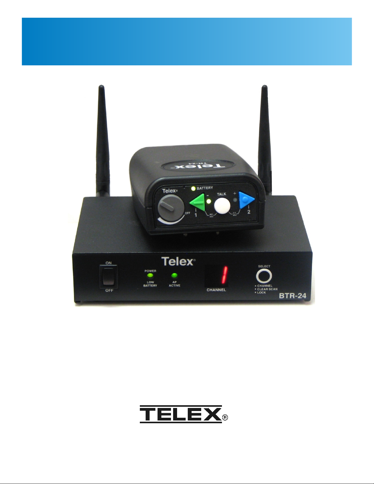
Operating Manual
BTR-24
TR-24
Wireless Intercom System
Bosch Communications Systems
Page 2

Table of Contents
Section 1 Introduction .................................................................1-1
General Description.....................................................................1-1
System Features........................................................................1-1
Section 2 BTR-24 Base Station ..........................................................2-1
Controls and Connections ................................................................2-1
Section 3 TR-24 Beltpack...............................................................3-1
Controls and Connections ................................................................3-1
Section 4 Specifications ................................................................4-1
System Technical Specifications ...........................................................4-1
Section 5 Operation ...................................................................5-1
Wireless Mode.........................................................................5-1
Description .......................................................................5-1
Set-up ...........................................................................5-2
System Operation ..................................................................5-2
Wired Mode...........................................................................5-3
Description .......................................................................5-3
Set-up ...........................................................................5-4
Network Requirements ..............................................................5-5
Master Wireless Mode...................................................................5-5
Description .......................................................................5-5
Set-up ...........................................................................5-5
System Operation ..................................................................5-6
Tour Group Example ...............................................................5-7
Battery Charging Instructions .............................................................5-7
Section 6 Encryption and Password ......................................................6-1
Encryption Code .......................................................................6-1
Login Password........................................................................6-1
Software Version.......................................................................6-1
Logging into a Unit .....................................................................6-1
User Menu Options .....................................................................6-2
Enter new password ................................................................6-2
Display current encryption key........................................................6-2
Enter new encryption key............................................................6-2
Exit .............................................................................6-2
Section 7 Battery Care/Long Term Storage ................................................7-1
Battery Care...........................................................................7-1
Long Term Storage .....................................................................7-1
Li-Ion Batteries ........................................................................7-1
Section 8 Trouble Shooting .............................................................8-1
Section 9 RF Channels .................................................................9-1
RF Channels ..........................................................................9-1
Section 10 Regulatory Information.......................................................10-1
Regulatory Information.................................................................10-1
Section 11 Accessories and Replacement Parts .............................................11-1
Page 3

Section 1 - Introduction
General Description
The Telex BTR-24 System is a full duplex (simultaneous talk and
listen), multi-channel, wireless intercom system. The system
offers a complete solution for up to 10, full duplex users per base
station, many more if in push-to-transmit mode. With fast and easy
set-up, durable beltpacks, 64 bit audio encryption, and
professional grade headsets.
The main components of this system consists of the TR-24
beltpack and the BTR-24 base station.
The TR-24 beltpack offers the user three audio channels; Audio
Channel 1, Audio Channel 2, and both audio's combined. The user
can talk and listen on these channels or just turn off the talk button
and listen only.
The beltpacks have the ability to communicate with each other in
wireless, wired or master wireless modes. In wireless mode,
beltpack communicate to each other using the base station as a
relay. In wired mode, beltpacks turn off their wireless ability and
communicate via an ethernet cable or a buildings ethernet
backbone. Finally in master wireless mode, a beltpack can become
base station and serve as the wireless relay for coverage over an
area.
The beltpack uses an internal rechargeable Li-Ion battery that will
provide up to 8 hours of uninterrupted operation.
System Features
• No FCC License required.
• Easy base station and beltpack setup.
• Uses mature 2.4GHz IEEE 802.11 Wireless LAN
Technology.
• A beltpack can serve as a base station if needed.
• Beltpacks can communicate to each other wired or wireless.
• Audio in the system is encrypted via a 64 bit DES algorithm.
• Base station automatically selects the clearest RF channel for
the system, and sets the system on that channel. No user
intervention is needed.
• Easy to read base station LED display to indicate the RF
channel of the system.
• If desired, the user can select any one of the eleven standard
802.11 channels for the system to operate via a single button
on the BTR-24 front panel.
• Durable, water resistant, ABS, beltpack cases.
The BTR-24 base station can support up to ten TR-24 beltpacks in
full duplex mode and more if in push-to-transmit mode. The base
station provides a central relay location which handles the audio
traffic between beltpacks. The built-in base station intelligence
called ClearScan™ automatically selects the best RF (Radio
Frequency) channel for communications on start-up. The base
station also uses an internal rechargeable Li-Ion battery that will
provide up to 10 hours of uninterrupted operation.
• Dependable, rechargeable, wide temperature range, Li-Ion
batteries.
• Low battery indications on the beltpack and base station.
• Base station and beltpacks can be powered from external AC
or internal battery.
1-1
Page 4
ONON
OFFOFF
LOW
BATTERY
POWER
AP
ACTIVE
CHANNEL
Telex
R
SELECT
CHANNEL
CLEAR SCAN
LOCK
BTR-24
1
2 3 4 5
Section 2 - BTR-24 Base Station
RED: CHARGING
GREEN: READY
PGM
TRANSMIT
ANTENNA
12 VDC
400mA
CORD
RETAINER
RECEIVE
ANTENNA
BTR-24
Telex Communications, Inc.
This device complies with Part 15 of the FCC Rules
Operation is subject to the following two conditions
(2) This device must accept any interference, received.
(1) This device may not cause harmful interference, and
Including interference that may cause undesired
operation.
Made in U.S.A. XXXXXXXXX
FCC ID:B5DM525
IC: 1321A-XOAP
S.N.: 000003
6
7 9
8
10
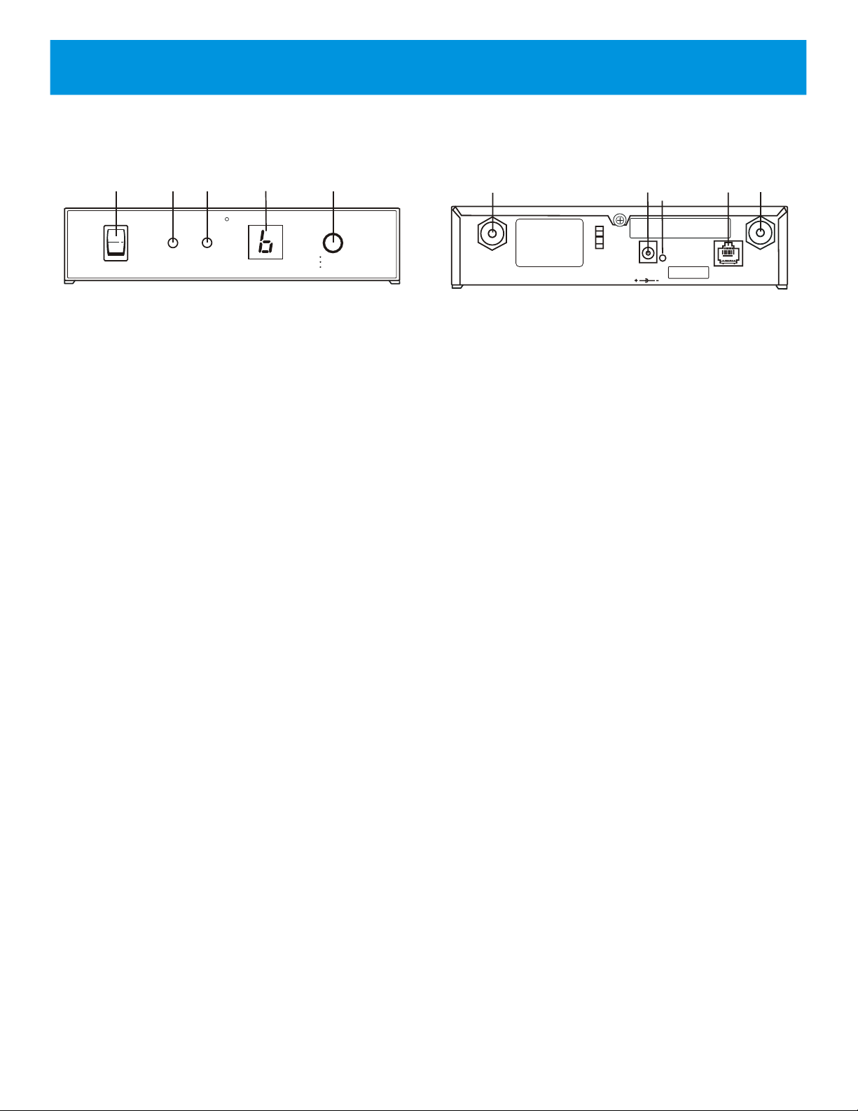
Controls and Connections
Front View
1. On/Off Switch – Turns the power on/off to the base station.
2. Power / Low Battery Light – Indicates the base station has
power, either from the internal battery or external power
connected to the unit.
Battery Indication:
• GREEN = Battery OK
• RED = Battery Low ( »30 minutes left)
• No Light = Battery Depleted
3. AP Active Light – This green light flashing indicates that the
AP has successfully booted and is operating.
4. RF Channel Display – Indicates the RF channel the unit is
set on.
5. Select Button – Press the button to select the desired RF
channel for the base station.
• ClearScan – Press and hold the button until the decimal
point starts to flash (about 3 seconds) then release. The
unit will examine the RF channels available, then select
the one with the least activity and set the AP on that
channel. NOTE: On boot the unit will ClearScan and
automatically select the cleanest RF channel.
Rear View
6. Receive Antenna Jack – Reverse TNC receive jack.
7. Charge/Power Jack – Used to charge the internal battery or
power the unit directly off a wall outlet. Accepts a 5.5mm x
2.5mm plug with the center positive. Must be supplied with a
12VDC regulated power supply with at least a 400mA
current capacity.
8. Charge Light.
• RED = Battery is charging.
• GREEN = Battery is charged.
9. Configuration Jack – RJ-45 jack is used to interface the
base station to an Ethernet cable. jack may be used for
configuring the base station or connecting multiple base
stations
10.
Transmit Antenna Jack – Reverse TNC transmit jack.
• Lock – Press and hold the button until the decimal point is
on solid (about 10 seconds) then release. The AP will be
locked on the channel displayed. To unlock, press and
hold the button again until the decimal point is off. Lock
makes the currently displayed channel difficult for a user
to accidentally change.
2-1
Page 5
Section 3 - TR-24 Beltpack
1
2
3
OFF
MIC
S.T.
A J
D
1
2
4
5
A J
D
CHG
EXT
6
7
8
9
(1) Microphone
Shield (-)
(2) Microphone
Audio (+)
(3) Headphone
High (+)
(4) Headphone
Low (-)
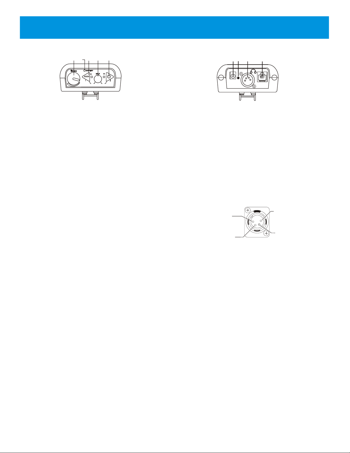
Controls and Connections
Top View
1. Volume Control and Power Switch – Turns the beltpack
power on/off and controls headset volume.
2. Battery Light/Power Light – Indicates the beltpack has
power, either from the internal battery or AC power
connected to the unit.
• GREEN = Battery Indication: battery OK
• RED = Battery Low (»15 minutes left)
• NO Light = Battery Depleted
3. Button One and Light – Selects audio channel one. The
channel light has two modes depending on the <TALK>
button's state.
• Light Solid = Talk and Listen enabled.
• Light Flashing = Listen only enabled. (Push-to-TX)
4. Talk Button – Enables the headset microphone. The button
has two modes:
• Momentary = Pressed and hold for over ½ second.
• Latch on/off = Tap button and the microphone path is
enabled. Tap again to turn off.
5. Button Two and Light – Selects Audio channel two. The
channel light has two modes depending on the <TALK>
button's state.
• Light Solid = Talk and Listen enabled.
• Light Flashing = Listen only enabled. (Push-to-TX)
Bottom View
6. Charge Jack – Used to charge the internal battery or power
unit directly off wall outlet. Accepts a 5.5mm x 2.5mm plug
with the center positive. Must be supplied with a 12VDC
regulated power supply with at least a 400mA current
capacity.
7. Charge Light.
• RED = Beltpack battery is charging.
• GREEN = Beltpack battery is charged.
8. Headset Connector – Standard 4-pin XLR connector.
Configuration Jack – RJ-45 jack used to interface the
9.
beltpack to an Ethernet cable. Jack may be used for wired
mode and configuring the beltpack.
Beltpack Button Combinations (All have voice prompts):
Wireless Mode .................Press <Talk> until unit is done
booting
Wired Mode .....................Press <TWO> until unit is done
booting.
Master Wireless Mode .....Press <ONE> until unit is done
booting.
Momentary Mode.............Press <ONE> + <TALK> + <TWO>
(Push-to-TX full time) for 3 seconds. Press the three buttons
again to go back to the default
"Push-to-Latch" mode.
Microphone Gain .............Press <ONE> + <TALK> for 3
seconds. Keep <TALK> held down
and use <ONE> to decrease the gain,
<TWO> to increase it. Release all
buttons for at lease 1 second to set.
Sidetone Level..................Press <TALK> + <TWO> for 3
seconds. Keep <TALK> held down
and use <ONE> to decrease the
level, <TWO> to increase it. Release
all buttons for at least 1 second to set.
3-1
Page 6

Section 4 - Specifications
System Technical Specifications
RF Technology............................................................................................................IEEE 802.11 (WiFi)
Frequency Band of Operation ......................................................................................2.412 to 2.462 GHz
FCC License ..............................................................................................................No License Required
Encryption Technology.............................................................64 bit (DES) Digital Encryption Standard
Audio Frequency Range................................................................................400 Hz to 5500 Hz (+/- 1dB)
Dynamic Range................................................................................................................................>75 dB
Beltpack Headset Output ............................................................200 mW into 300 Ohms (1% Distortion)
Beltpack Microphone Gain Adjustment .....................................................10 Levels with Voice Prompts
Antenna (TR-24)................................................................................................................Internal Dipoles
Antenna (BTR-24).......................................................................Multiple omni and Directional available
BTR-24 (Base Station) Battery .........................................................................Lithium-Ion Rechargeable
BTR-24 Battery Life...........................................................................................................10 Hr (Typical)
BTR-24 Recharge Time ................................................................................................10-14 Hr (Typical)
BTR-24 Low Battery Indication...................................................30 minutes of battery life left (Typical)
TR-24 (Beltpack) Battery..................................................................................Lithium-Ion Rechargeable
TR-24 Battery Life ...............................................................................................................8 Hr (Typical)
TR-24 Recharge Time.......................................................................................................6-8 Hr (Typical)
TR-24 Low Battery Indication......................................................15 minutes of battery life left (Typical)
BTR-24 (Base Station)Size........................6.00” L x 7.63” W x 1.72” H (15.24cm x 19.37cm x 4.37cm)
BTR-24 Weight..............................................................................................................2 lb 11 oz (1.2 kg)
TR-24 Size ...................................................5.25” L x 3.75” W x 1.68” H (13.33cm x 9.53cm x 4.27cm)
TR-24 Weight........................................................................................................................12.5oz (354g)
Carry Case Size....................................23.50” L x 8.50” W x 20.50” H (59.70cm x 21.60cm x 52.07cm)
Carry Case Weight ......................................................(Not Loaded with Equipment)12 lb 8 oz (5.44 kg)
4-1
Page 7
Section 5 - Operation
ON
OFF
LOW
BATTERY
POWER
AP
ACTIVE
CHANNEL
Telex
R
SELECT
CHANNEL
CLEAR SCAN
LOCK
BTR-24
Telex
TR-24
R
Telex
TR-24
R
Telex
TR-24
R
Telex
TR-24
R
Telex
TR-24
R
Telex
TR-24
R
Telex
TR-24
R
Telex
TR-24
R
Telex
TR-24
R
Telex
TR-24
R
ON
OFF
LOW
BATTERY
POWER
AP
ACTIVE
CHANNEL
Telex
R
SELECT
CHANNEL
CLEAR SCAN
LOCK
BTR-24
ON
OFF
LOW
BATTERY
POWER
AP
ACTIVE
CHANNEL
Telex
R
SELECT
CHANNEL
CLEAR SCAN
LOCK
BTR-24
CONNECTED BY ETHERNET CABLE
LOCATION
1
LOCATION
2
Telex
TR-24
R
Telex
TR-24
R
Telex
TR-24
R
Telex
TR-24
R
Telex
TR-24
R
Telex
TR-24
R
Telex
TR-24
R
Telex
TR-24
R
Telex
TR-24
R
Telex
TR-24
R
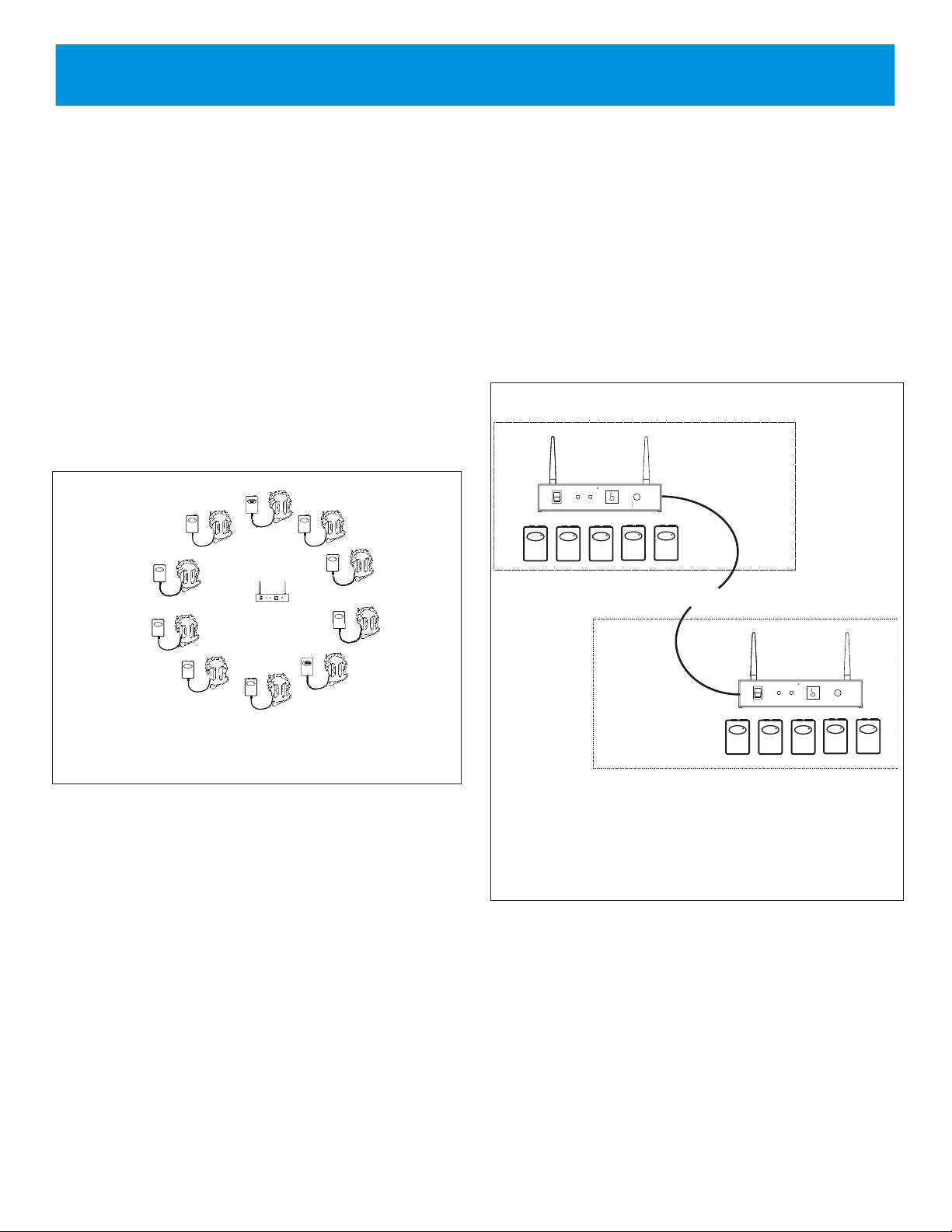
Wireless Mode
Description
The TR-24 has the ability to be booted in one of three modes.
These modes are wireless, wired and master wireless. This
section will discus the wireless mode.
The wireless mode is the most used mode of the beltpack. The
wireless mode is set by holding the <TALK> button down as the
unit boots. Then release it once a channel LED has lit indicating
communication has started. In this mode the beltpack’s radio is
active and the bottom RJ-45 Ethernet connection is deactivated.
The beltpack communicates to other beltpacks wireless via a base
station (This base station could be another beltpack if it was set to
boot in master wireless mode.). The base station serves as a
“relay” for audio packets going between beltpacks. One base
station can serve up to ten beltpacks in full duplex mode
(simultaneous talk and listen).
Multiple base stations can also be utilized in an installation. The
base stations have the ability to communicate to each other via an
Ethernet network connected to the RJ-45 jack on the rear panel.
The connection between bases could be a direct connection via an
Ethernet cable (100m, 328ft Max.) or connected via the
building’s Ethernet infrastructure (See “Network Information” in
the “Wired Mode” discussion for details.). Due to the base
station’s wired interconnection, the beltpacks of the various base
stations can communicate with each other.
Ten full duplex beltpacks is still the limit even if multiple base
stations, connected via Ethernet, in non-overlapping RF coverage
areas, are in a system.
Figure 5-1
Ten Beltpacks in Wireless Mode
With ten beltpack in full duplex, up to 28 additional beltpacks can
work off the base station if these beltpacks are in Push-to-TX
mode. In Push-to-TX mode the beltpacks are listen only and the
beltpacks’ channel lights are flashing until the <TALK> button is
active. At that point the beltpack transmits full time and is in full
duplex mode until user disables the <TALK> button again.
NOTE: Only ten full duplex beltpacks can work off a base
station. Thus the number of full duplex beltpacks on that base
must be reduce by the number of Push-to-TX beltpacks that could
become full duplex if their users press the talk button.
For example, a base station has 6 full duplex beltpacks and 28
Push-to-TX beltpacks. Up to 4 of the 28 Push-to-TX beltpacks
could go to full duplex at the same time without reaching system
limitations. If 5 of the Push-to-TX were to become full duplex, for
a total of 11 full duplex beltpacks, the system would go beyond its
loading limit and all users will start to experience drop outs and
delays in audio.
Figure 5-2
Two Ethernet connected base stations in two different
locations.
5-1
Page 8

Set-up
ONON
OFFOFF
LOW
BATTERY
POWER
AP
ACTIVE
CHANNEL
Telex
R
SELECT
CHANNEL
CLEAR SCAN
LOCK
BTR-24
RED: CHARGING
GREEN: READY
PGM
TRANSMIT
ANTENNA
12 VDC
400mA
CORD
RETAINER
RECEIVE
ANTENNA
BTR-24
Telex Communications, Inc.
This device complies with Part 15 of the FCC Rules
Operation is subject to the following two conditions
(2) This device must accept any interference, received.
(1) This device may not cause harmful interference, and
Including interference that may cause undesired
operation.
Made in U.S.A. XXXXXXXXX
FCC ID:B5DM525
IC: 1321A-XOAP
S.N.: 000003
R
Below are instructions for the set-up and operation of a single
BTR-24 with up to ten TR-24's.
Figure 5-3
Front and Rear of BTR-24
Prior to use the TR-24 and BTR-24 should have their battery
1.
packs fully charged. Refer to the “Battery Charging
Instructions” near the end of this section.
2. Plug the BTR-24's external power supply into an AC outlet if
available. If external power is not available then the unit can
run off internal battery.
3.
Connect the antennas to the BTR-24.
4. Place the BTR-24's antennas in a location where they will
have the best line-of-site to the area of coverage.
• After 20 seconds a beltpack voice prompt will announce
“wireless” in the headphone.
• Audio channel one’s light will activate indicating
communication has started.
System Operation
By following the previous setup instruction, the system should
now be up and running. Please read the following information for
optimization / best performance of that system.
Beltpack position - When operating the system, wear the
beltpack on the hip. Place it in a position that allows for greatest
visibility to the BTR-24 antennas. The internal antennas for the
TR-24 are on the sides of the beltpack case. For best visibility of
antennas, do not place other objects within 6 inches (15cm) of the
beltpack on the belt.
NOTE: The BTR-24 system operates in the 2.4 GHz spectrum.
Keep coaxial cables as short as possible to reduce signal loss in
the cable.
5. Power the BTR-24 by turning the power switch to ON.
• The power light should immediately light solid.
• After 20 seconds the base station will clear scan the
spectrum and place the unit on the best RF channel.
• After the scan, the AP Active light will flash, indicating a
successful boot.
• After the boot the user may clear scan again, manually set
a RF channel or lock a channel. See section 2, “BTR-24
Controls and Connection”, for details.
6. Plug headsets into the TR-24 beltpacks.
7. When the BTR-24 has finished booting, power-up the TR-24
beltpacks in wireless mode. The wireless mode is entered by
holding the <TALK> button down as the unit boots. Once a
beltpack was booted in a mode (wireless, wired, master
wireless), the beltpack will always boot in that mode until the
user sets a different boot mode.
• The power light should immediately light solid.
Figure 5-4
Beltpack on Hip
Beltpack Audio Channels -Press the <1> button for audio
channel one only. Press the <2> for audio channel two only.
Press both <1> and <2> buttons simultaneous to select both. Use
the talk button to select between enabling / disabling the headset
microphone path. The channel light(s) will blink if the
microphone path is disabled. The light(s) will be solid if the
microphone path is enabled. See table below for talk modes:
5-2
Page 9

<TALK> Mode Description Activation
OFF
BATTERYBATTERY
TALKTALK
MIC
TelexTelex
S.T.
A J
D
++
1
2
A J
D
BUILDING
INTRASTRUCTURE
H
U
B
H
U
B
Telex
TR-24
R
Telex
TR-24
R
Telex
TR-24
R
Telex
TR-24
R
Telex
TR-24
R
H
U
B
H
U
B
Telex
TR-24
R
Telex
TR-24
R
Telex
TR-24
R
H
U
B
H
U
B
Telex
TR-24
R
Telex
TR-24
R
Location
1
Location
2
Push-to-Latch/
Momentary
(default mode)
Momentary Only
(Push-to-TX)
Microphone is
enabled until the
button is tapped
again.
If held down for 1/2
second the
microphone path is
disabled on release.
<TALK> button
enables the audio
path for only as long
as it is held down.
The beltpack will be
in this mode until
reset to
push-to-latch mode.
Tap <TALK>
button. Tap again
to turn off.
<TALK> held
down for over 1/2
second.
Press <1> +
<TALK> + <2>
until voice
prompt indicates
momentary mode
(about 3
seconds). Do
again to go back
to push-to-latch
mode.
Sidetone Level Adjust – Press <TALK> + <2> until a voice
prompt indicates sidetone adjust mode has been entered (about 3
seconds). Keep holding <TALK> down and use the <1> button
to decrease the level, <2> button to increase the level. Voice
prompts will indicate the current level setting. Release all buttons
for at least one second and the level will be set.
Wired Mode
Description
The TR-24 has the ability to be booted in one of three modes.
These modes are wireless, wired and master wireless. This
section will discuss the wired mode.
The wired mode is set by holding the <2> button down as the unit
boots. Then release it once a channel LED has lit indicating
communication has started. In this mode the beltpack’s radio is
deactivated and the bottom RJ-45 Ethernet connection is active.
The beltpacks communicate to each other via an Ethernet
network connected to the RJ-45 jack on the bottom of the unit.
No base stations are required for beltpacks to communicate with
each other in this mode. The connection between beltpacks could
be a direct connection via an Ethernet cable (100m, 328ft Max.)
or connected via the building’s Ethernet infrastructure (See
“Network Information” for more discussion of details.).
Figure 5-5
Top View of TR-24
The sidetone (amount of your own voice fed back to your
earphones) and microphone gain of the beltpacks may need
adjusted from the factory defaults. The defaults are:
• Microphone Level = 4
• Sidetone Level = 2
Microphone Level Adjust – Press <1> + <TALK> until a voice
prompt indicates microphone adjust mode has been entered
(about 3 seconds). Keep holding <TALK> down and use the <1>
button to decrease the level, <2> button to increase the level.
Voice prompts will indicate the current level setting. Release all
buttons for at least one second and the level will be set.
Figure 5-6
Ten TR-24's communicating via Ethernet Backbone.
5-3
Page 10

Up to ten beltpacks, in full duplex (simultaneous talk and listen),
H
U
B
H
U
B
Telex
TR-24
R
Telex
TR-24
R
Telex
TR-24
R
Telex
TR-24
R
Telex
TR-24
R
Telex
TR-24
R
Telex
TR-24
R
Telex
TR-24
R
Telex
TR-24
R
Telex
TR-24
R
ON
OFF
LOW
BATTERY
POWER
AP
ACTIVE
CHANNEL
Telex
RR
SELECT
CHANNEL
CLEAR SCAN
LOCK
BTR-24
OFF
BATTERYBATTERY
TALKTALK
MIC
TelexTelex
S.T.
A J
D
++
1
2
A J
D
may communicate with each other over a Ethernet network. In
fact do to the flexibility of the BTR-24 system, wired beltpacks
connected via a hub to a network could communicate to a BTR-24
connected to the same network. This base station could then be
connected wirelessly to other TR-24s operating in wireless mode.
4. Plug headsets into the TR-24 beltpacks.
5. Power-up the TR-24 beltpacks in wired mode. The wired
mode is entered by holding the <1> button down as the unit
boots. Once a beltpack was booted in a mode (wireless,
wired, master wireless), the beltpack will always boot in that
mode until the user sets a different boot mode.
• The power light should immediately light solid.
• After 20 seconds a beltpack voice prompt will announce
“wired” in the headphone (The "wired" announcement
will be followed by the software version within the unit.).
• Audio channel one’s light will activate indicating
communication has started.
Beltpack Audio Channels - Press the <1> button for audio
channel one only. Press the <2> button for audio channel two
only. Press both <1> and <2> buttons simultaneous to select
both. Use the talk button to select between enabling / disabling
the headset microphone path. The channel light(s) will blink if the
microphone path is disabled. The light(s) will be solid if the
microphone path is enabled. See table below for talk modes:
<TALK> Mode Description Activation
Push-to-Latch/
Momentary
Figure 5-7
Five Wired TR-24's communicating with 5 wireless
TR-24's
Set-up
Below are instructions for the set-up and operation of a TR-24s
connected via an Ethernet backbone.
1. Prior to use the TR-24 should have their battery packs fully
charged. Refer to the “Battery Charging Instructions” near
the end of this section.
2. Plug the TR-24’s external power supply into an AC outlet if
desired. If external power is not desired then run off internal
battery.
(default mode)
Momentary Only
(Push-to-TX)
Microphone is
enabled until the
button is tapped
again.
If held down for 1/2
second the
microphone path is
disabled on release.
<TALK> button
enables the audio
path for only as long
as it is held down.
The beltpack will be
in this mode until
reset to
push-to-latch mode.
Tap <TALK>
button. Tap again
to turn off.
<TALK> held
down for over 1/2
second.
Press <1> +
<TALK> + <2>
until voice
prompt indicates
momentary mode
(about 3
seconds). Do
again to go back
to push-to-latch
mode.
3. Connect the TR-24(s) to each other via an Ethernet
backbone. Use category 5e or better Ethernet cables that are
wired to standards T-568A or T-568B (Most all Ethernet
cables are built to these standards).
NOTE: Either straight through or crossover Ethernet cables
my be used. The beltpack and base station automatically
detect which type is connected.
Figure 5-8
Top View of TR-24
5-4
Page 11

The sidetone (amount of your own voice fed back to your
Telex
TR-24
RR
MASTER TR-24
SERVING AS A
BASE STATION
Telex
TR-24
RR
Telex
TR-24
RR
Telex
TR-24
RR
Telex
TR-24
RR
Telex
TR-24
RR
Telex
TR-24
RR
Telex
TR-24
RR
Telex
TR-24
RR
Telex
TR-24
RR
earphones) and microphone gain of the beltpacks may need
adjusted from the factory defaults. The defaults are:
• Microphone Level = 4
• Sidetone Level = 2
Microphone Level Adjust – Press <1> + <TALK> until a voice
prompt indicates microphone adjust mode has been entered
(about 3 seconds). Keep holding <TALK> down and use the <1>
button to decrease the level, <2> button to increase the level.
Voice prompts will indicate the current level setting. Release all
buttons for at least one second and the level will be set.
Sidetone Level Adjust – Press <TALK> + <2> until a voice
prompt indicates sidetone adjust mode has been entered (about 3
seconds). Keep holding <TALK> down and use the <1> button
to decrease the level, <2> button to increase the level. Voice
prompts will indicate the current level setting. Release all buttons
for at least one second and the level will be set.
Network Requirements
These network requirements apply to interconnect BTR-24s as
well as TR-24 in wired mode. In general the TR-24 and BTR-24s
following the same rules as other Ethernet networked devices.
These rules are:
Description IP Type Destination IP Protocal
Audio 1
Packet
Audio 2
Packet
Audio 1 + 2
Packet
Multicast 239.192.168.1 UDP
Multicast 239.192.168.2 UDP
Multicast 239.192.168.3 UDP
TR-24/BTR-24 Wired Data Packets
Master Wireless Mode
Description
The TR-24 has the ability to be booted in one of three modes.
These modes are wireless, wired and master wireless. This
section will discuss the master wireless mode.
The master wireless mode is set by holding the <1> button down
as the unit boots. Then release it once a channel LED has lit
indicating communication has started. In this mode the beltpack’s
radio is active and the bottom RJ-45 Ethernet connection is
deactivated. This beltpack not only still functions as a beltpack,
its now acting as a base station as well. One master beltpack can
serve up to 9 other full duplex beltpacks.
1. All TR-24s and BTR-24 must have unique IP (Internet
Protocol) addresses. This means no TR-24s or BTR-24s in a
network should have the same IP address. Also, no other
devices on the wired network should have the same IP
addresses as the BTR-24s and TR-24s to be used.
2. Use category 5e or better Ethernet cables that are wired to
standards T-568A or T-568B (Most all Ethernet cables are
built to these standards.).
3. If direct connecting TR-24s or BTR-24s together, without
the use of a building’s network infrastructure, do not use
more than 100m (328ft) of Ethernet cable between devices.
4. If using an existing building’s Ethernet network, consult
your network administrator as to the locations you plan on
connecting your TR-24 or BTR-24s to the network. They
can then check to make sure distance limitations of the
network are met and that existing in-house router/switchers
are set to pass TR-24 and BTR-24 packets.
NOTE: All TR-24 and BTR-24 devices will appear to have
the same MAC address to a network.
Figure 5-9
One master TR-24 serving 9 other TR-24's
Set-up
Below are instructions for the set-up and operation of a single
master TR-24 serving as a base station for up to nine other
TR-24s.
1. Prior to use the TR-24s should have their battery packs fully
charged. Refer to the “Battery Charging Instructions” near
the end of this section.
5-5
Page 12

2. Plug the master TR-24’s external power supply into an AC
R
OFF
MIC
S.T.
A J
D
1
2
A J
D
outlet if desired. If external power is not desired then run off
internal battery.
3. Place the TR-24’s in a location where it will have the best
visibility to the other TR-24s.
4. Plug a headset into the master TR-24 beltpack.
5. Power-up the master TR-24 beltpack in master wireless
mode. The master wireless mode is entered by holding the
<1> button down as the unit boots. Once a beltpack was
booted in a mode (wireless, wired, master wireless), the
beltpack will always boot in that mode until the user sets a
different boot mode.
• The power light should immediately light solid.
• After 20 seconds a beltpack voice prompt will announce
“master wireless” in the headphone.
• Audio channel one’s light will activate indicating
communication has started.
6. Plug headsets into TR-24 beltpacks.
7. When the master TR-24 has finished booting, power-up the
TR-24 beltpacks in wireless mode. The wireless mode is
entered by holding the <TALK> button down as the unit
boots. Once a beltpack was booted in a mode (wireless,
wired, master wireless), the beltpack will always boot in that
mode until the user sets a different boot mode.
• The power light should immediately light solid.
• After 20 seconds a beltpack voice prompt will announce
“wireless” in the headphone.
• Audio channel one’s light will activate indicating
communication has started.
System Operation
By following the previous setup instruction, the system should
now be up and running. Please read the following information for
optimization / best performance of that system.
Beltpack position - When operating the system, wear the
beltpack on the hip. Place it in a position that allows for greatest
visibility to the master TR-24 antennas. The internal antennas for
the TR-24 are on the sides of the beltpack case. For best visibility
of antennas, do not place other objects within 6 inches (15cm) of
the beltpack on the belt.
Figure 5-10
TR-24 Beltpack on Hip
Beltpack Audio Channels -Press the <1> button for audio
channel one only. Press the <2> for audio channel two only.
Press both <1> and <2> buttons simultaneous to select both. Use
the talk button to select between enabling / disabling the headset
microphone path. The channel light(s) will blink if the
microphone path is disabled. The light(s) will be solid if the
microphone path is enabled. See table below for talk modes:
<TALK> Mode Description Activation
Push-to-Latch/
Momentary
(default mode)
Momentary Only
(Push-to-TX)
Microphone is
enabled until the
button is tapped
again.
If held down for 1/2
second the
microphone path is
disabled on release.
<TALK> button
enables the audio
path for only as long
as it is held down.
The beltpack will be
in this mode until
reset to
push-to-latch mode.
Tap <TALK>
button. Tap again
to turn off.
<TALK> held
down for over 1/2
second.
Press <1> +
<TALK> + <2>
until voice
prompt indicates
momentary mode
(about 3
seconds). Do
again to go back
to push-to-latch
mode.
Figure 5-11
Top View of TR-24
5-6
Page 13

The sidetone (amount of your own voice fed back to your
Telex
TR-24
R
TOUR GUIDE
Telex
TR-24
R
Telex
TR-24
R
Telex
TR-24
R
Telex
TR-24
R
Telex
TR-24
R
Telex
TR-24
R
Telex
TR-24
R
Telex
TR-24
R
Telex
TR-24
R
Telex
TR-24
R
Telex
TR-24
R
Telex
TR-24
R
Telex
TR-24
R
Telex
TR-24
R
Telex
TR-24
R
Telex
TR-24
R
TOUR GROUP
Telex
TR-24
R
Telex
TR-24
R
Telex
TR-24
R
Telex
TR-24
R
Telex
TR-24
R
Telex
TR-24
R
Telex
TR-24
R
Telex
TR-24
R
Telex
TR-24
R
Telex
TR-24
R
Telex
TR-24
R
Telex
TR-24
R
earphones) and microphone gain of the beltpacks may need
adjusted from the factory defaults. The defaults are:
• Microphone Level = 4
• Sidetone Level = 2
Microphone Level Adjust – Press <1> + <TALK> until a voice
prompt indicates microphone adjust mode has been entered
(about 3 seconds). Keep holding <TALK> down and use the <1>
button to decrease the level, <2> button to increase the level.
Voice prompts will indicate the current level setting. Release all
buttons for at least one second and the level will be set.
Sidetone Level Adjust – Press <TALK> + <2> until a voice
prompt indicates sidetone adjust mode has been entered (about 3
seconds). Keep holding <TALK> down and use the <1> button
to decrease the level, <2> button to increase the level. Voice
prompts will indicate the current level setting. Release all buttons
for at least one second and the level will be set.
Figure 5-12
Tour Group Application
Tour Group Example
A good example of a master wireless mode application is a tour
group within a noisy manufacturing environment.
As shown in the Figure, a single TR-24 is set to boot in “master
wireless”. This beltpack would be worn by the tour guide. The
rest of the beltpacks are set to boot in “wireless” mode and
Push-to-TX (Push-to-TX beltpacks have their <TALK> button
set to momentary only). The tour group would wear these
beltpacks.
The group size could be up to 28 people (or more) when the
beltpacks are in Push-to-TX mode. This is because when in
Push-to-TX mode the beltpacks are listen only, until the
<TALK> button is active. At that point the beltpack transmits full
time and is in full duplex mode until user releases the <TALK>
button again. The group’s TR-24s could also be used in
push-to-latch mode (full duplex) for this application, but due to
the greatly increase bandwidth requirement for this talk mode the
group’s size would be limited to 9 (Ten total if you include the
tour guide's master beltpack).
NOTE: Only 9 full duplex beltpacks can work off a master
beltpack. Thus the number of full duplex beltpacks working off
that master beltapck must be reduce by the number of Push-to-TX
beltpacks that could become full duplex, at the same time, if their
users press the talk button.
Battery Charging Instructions
Charge the BTR-24 and TR-24 internal battery as follows:
1. Ensure the TR-24 beltpacks are in the “OFF” position.
2. Ensure the BTR-24 base stations are in the “OFF” position.
3. TR-24 beltpack: Plug the charger into the charge jack on the
bottom of the beltpack. The beltpack should be charged in a
room temperature location. The LED on the bottom of the
unit indicates the charge status.
• RED = Charging
• GREEN = Charging Done
A fully discharged beltpack will need to charge for at least 6
– 8 hours.
Beltpacks may be left on charge indefinitely.
4. BTR-24 base station: Plug the charger into the charge jack
on the bottom of the base station. The base should be
charged in a room temperature location. The LED on the
bottom of the unit indicates the charge status.
• RED = Charging
• GREEN = Charging Done
A fully discharged base station will need to charge for at least
10 – 14 hours.
The BTR-24 may be left on charge indefinitely.
5-7
Page 14

Section 6 - Encryption Code and Password
Encryption Code
The BTR/TR-24 system uses a 64 bit DES (Digital Encryption
Standard) encryption algorithm to encrypt all audio in the system.
The beltpacks in the system have a “key” that the algorithm uses
as the basis for the encryption. The same “key” must be used in all
beltpacks on the system for communication to occur. The base
station only relays the audio, and as such, does not need any
encryption code set. The beltpack key can be anything from
numbers to sentences to hexadecimal letters. For example the
phrase, “The BTR-24 system works great for our customers”,
could be the “key” for the encryption. The only criteria is the
phrase/numbers/letters be no more than 80 characters long (this
includes spaces and punctuation).
This encryption is running on all units from the factory and does
not have to be “activated" by the user. The user may want to
change their key to something unique. Please see the "Logging
into a unit" instructions in this section for details on changing the
encryption key.
Login Password
When a user logs into a beltpack or base station, he or she must
enter a user login and password in order to proceed to the user
menu.
• Login: telex
• Ethernet straight thru or crossover cable (Use the green
cable supplied with the system.)
Operating System
Microsoft® Windows® 95/98, NT, 2000, XP
Software
Telnet or similar application that lets you communicate to a
specified IP Address (Most all computers have telnet or a similar
program installed on them by default).
The following instructions use Telnet and Windows® 2000 to log
into the beltpack. Other applications and operating systems will
be similar.
1. Unplug any current RJ-45 network connections from the
computer.
2.
With the mouse, right click the My Network Places con,
then select Properties.
3.
Select Local Area Connection and then right click. Select
Properties.
4.
Select Internet Protocol (TCP/IP) and click on the
Properties button.
• Password: legacy
The login of "telex" cannot be changed, but for increased security
the password can be changed via the user menu. Please see the
"Logging into a Unit" instructions in this section for details on
changing the password.
Software Version
Below the password prompt on the user configuration menu
screen (See Figure 6-1), the software version of the unit is
displayed. Pay close attention to the revision letter and the date.
These are the two items that change if the software changes. The
line below the software version indicates the system type. All the
units should indicate TR-24/BTR-24 on this line.
In addition to the software version being displayed on the user
configuration screen, if a beltpack is booted in wired mode, it will
announce the software revision letter one second after the "wired"
voice prompt is heard.
Logging into a Unit
Computer Requirements:
Hardware
• Monitor
• Keyboard & Mouse
• Network card (10 BaseT or 100 BaseT)
5.
Now select “Use the following IP address:” option. Make a
note of your current settings on this screen (so you can place
them back when done logging into the beltpacks).
Enter the following:
a. IP address: 192.168.1.40
b. Subnet Mask: 255.255.255.0
c. Default gateway: 192.168.1.1
6.
Once the above information is entered, hit the OK button. Hit
the OK button on the next screen out if needed. Depending
on your computer, you may need to reboot the computer for
the IP address changes to take effect.
7. Plug one end of the supplied green Ethernet cable into the
computer.
8. Start a “command prompt” console window by clicking on
“Start” then moving the mouse arrow to Programs, then
Accessories and finally clicking on “Command Prompt”.
9. Press and hold down the “2” button on the beltpack. Keep
holding the “2” button and turn-on the beltpack. Hold the
beltpack button down until the green LED next to the “2”
button lights up (about 20 seconds), then release button
(Places the beltpack in wired mode).
6-1
Page 15

Plug the other end of the Ethernet cable into the beltpack.
10.
Enter new encryption key
3.
11. Type, telnet 192.168.1.X at the computer’s command
prompt, then press <ENTER>. Fill in for X the last digit of
the IP address that is on the back label on the TR-24.
12. After about 20 seconds the beltpack will respond with a login
request. Enter the following:
• Login: telex <ENTER>
• Password: legacy <ENTER>
NOTE: The password entry does not give user feedback to
the screen.
NOTE: If the computer says, “failed to connect”, turn off the
TR-24, check computer settings, and go back to step 6.
User Menu Options
Once successfully logged into the base station or beltpack you
will be presented with the following screen:
The user must change the encryption key if this option is selected.
Since a base station acts only as a relay for the audio packets it is
not necessary to change its encryption key.
1. When “3” is selected the phrase, “Enter new
encryption key” appears.
2. Now enter the new encryption key. The maximum
length is 80 characters. Any combination of
letters/numbers/punctuation may be used. Even a
sentence such as, “My system is the best in the
studio”, may be used as the key. The key is upper and
lower case sensitive.
NOTE: A character is letters, numbers, punctuation, spaces, etc.
NOTE: The “backspace” keyboard button may not work on all
computers using Telnet, use the delete button instead if this is the
case.
CAUTION: Write down the key or use one that you can
remember, because ALL beltpacks must have the same key
entered in order for communication.
Figure 6-1
User's Menu Screen
The four options on this screen are as follows:
1. Enter new password
This option allows the user to change this TR-24’s password. The
default from the factory is legacy. The user is never allowed to
change the login name of telex.
3. Press <ENTER> after the key is typed. This will
place the key in the software. Reboot the beltpack for
the new encryption key to take effect.
4. Exit
This exits the login and closes the connection to the base station
or beltpack.
2. Display current encryption Key
Displays on the screen the current encryption key of the beltpack.
6-2
Page 16

Section 7 - Battery Care/Long Term Storage
Battery Care
To ensure the long life and safe handling of the Li-Ion battery
within the BTR-24 and TR-24 please following the following
precautions:
1. Store the TR-24s and BTR-24 in a clean, cool, dry location
away from heat.
2. Do not store for extended periods of time in direct sunlight.
3. Do not disassemble the battery packs within the TR-24 or
BTR-24.
4. Do not apply solder directly to the pack.
5. Do not puncture/crush or subject the TR-24 or BTR-24 to
excessive impact.
6. Dispose of unit in proper recycling location for a device with
a Li-Ion battery.
Li-Ion Batteries
The Li-Ion batteries used in the TR-24 and BTR-24 are excellent
batteries for portable, indoor/outdoor applications. They have a
high energy density (energy per weight) compare to other
rechargeable battery technologies (NiCd, NiMH, Alkaline, Gel
Cells), are low maintenance, and offer superior performance at
low temperatures.
For best performance after long-term storage, Telex recommends
the batteries be charged to 30% - 50% of capacity before being
placed in storage. This is the typical battery capacity left after 4 –
6 hours of full duplex use. Li-Ion batteries retain nearly all their
capacity if stored for long term in dry, cool temperatures with
only 30% to 50% charge. They can lose up to 20% capacity if
stored for long term right after being fully charged.
Long Term Storage
“Long term storage” of the system is defined as no use of the
system for 1 month or longer. Due to the internal Li-Ion batteries
of the TR-24 and BTR-24, care should be taken in long term
storage. Use the following steps to ensure the best performance
of the system after it comes out of storage.
1. After the last event:
• If the TR-24 or BTR-24 batteries were used for four hours
or less then do not recharge the internal TR-24 or BTR-24
batteries. (Please see the discussion of “Li-Ion batteries”
in the follow part of this section as to why)
• If the TR-24 or BTR-24 batteries were used for more then
four hours then recharge the internal TR-24 or BTR-24
batteries for two hours then take them off charge (Please
see the discussion of Li-Ion batteries in the follow part of
this section as to why)
2. Store the TR-24s and BTR-24 in a clean, cool, dry location
away from heat. The temperature of the storage location
should not rise above room temperature. The recommended
temperature range of the storage location is 32 - 77° F (0 –
25° C).
3. Every 6 months charge the BTR-24 and TR-24 for three
hours then take off charge. Do not fully charge. This
prevents the battery from over discharging and helps
maintain the battery’s performance.
7-1
Page 17

Section 8
Please reread the operation and encryption/password section of
this manual to make sure you have completed system set-up
properly. The following contains troubleshooting tips that may be
helpful in solving the problem.
Problems Possible Cause Solution
RF range of all the beltpacks is less than
normal and/or beltpacks are experiencing
“break-up” of audio in an area where they
have worked well in the past.
• Antenna is not connected to the
BTR-24.
• The two antenna connections are not
connected to the right connectors on
the BTR-24.
• WiFi RF interference has occurred.
If you are unable to solve the problem, contact the manufacturer
or dealer from whom you purchased the system for assistance.
• Connect the antenna(s) to the BTR-24. If
antenna has cables, make sure the
correct cable of the antenna goes to the
corresponding connector on the
BTR-24. The BTR-24 front label
indicates the transmit and receive
connectors.
• The BTR-24 rear label indicates the
transmit and receive connectors. If the
antenna has cables the cables are labeled
as to their connection point.
• Find the source of the interference and
shut it down. Sources of WiFi
interference could be: Laptop/Desktop
computer with its wireless card on or
WiFi AP in or near the press box.
• Non-WiFi RF Interference has
occurred.
• If the interference cannot be found or
shut off then press and hold the
<SELECT> button for 3 seconds (until
the decimal point flashes), then release.
The unit will do a clear scan and place
itself on the clearest channel. The
beltpacks do not have to be turned off,
they will follow the BTR-24 to the new
channel within a few seconds after the
clear scan is done.
• Find the source of the interference and
shut it down. Sources of interference
could be: Microwave oven in, 2.4GHz
cordless phone nearby, using a
Bluetooth headset near the BTR-24 or
beltpack.
• If the interference cannot be found or
shut off then manually select a different
RF channel by hitting the <SELECT>
button. Make sure the new channel is at
least several channels away from the old
channel for the best chance of avoiding
the RF interference. The beltpacks do
not have to be turned off, they will
follow the BTR-24 to the new channel
after a few seconds.
8-1
Page 18

Section 8 - Troubleshooting continued
Problem Possible Cause Solution
When the BTR-24 power switch was turned
on nothing happens. The power light does not
light.
When the BTR-24 power switch was turned
on, the unit's power light came on but the
system never booted-up after 25 seconds.
Can't change the RF channel the BTR-24 is
on.
When the TR-24 beltpack power was turned
on, the unit's power light came up, but the "1"
button light never came up and
communication never started.
• Internal battery is completely
exhausted
• Internal battery is nearly exhausted.
• On boot, an error was encountered and
the unit could not finish boot-up.
• The base station may be set to channel
lock. This is indicated by a solid
decimal point in the bottom right of the
display.
• Internal battery is nearly exhausted.
• On boot, and error was encountered
and the unit could not finish boot-up
• Plug the AC power plug into the
BTR-24. Allow the unit at least 5
minutes for the internal battery to
receive an initial charge. Then turn the
unit on and run it off AC power.
• Charge the battery or run off external
AC power.
• Power down the BTR-24, wait two
seconds, then power-up again.
• Hold the <SELECT> button down for
about 10 seconds. This unlocks the RF
channel lock button. A user could also
reboot the BTR-24, but the beltpacks
would need to be turned off until the
BTR-24 finished booting, then turned
on.
• Charge the battery.
• Power down the TR-24, wait two
seconds, then power up again.
Headphone audio from another beltpack(s) is
loud and distorted.
Headphone audio from another beltpack(s) is
too low.
• Microphone gain on the other
beltpack(s) is set to high.
• The headset's microphone on the other
beltpack(s) is too far from the user's
mouth.
• Microphone gain on the other
beltpack(s) is set too low.
• Press and hold the <TALK> button and
"1" button until the voice prompt
indicates "MIC ADJUST" on the
offending beltpack. While holding the
<TALK> button, press and hold the "1"
button to lower microphone gain. The
factory setting is at the voice prompt
"four" level.
• Adjust the headset's microphone on the
suspected beltpack so it is one index
finger width straight out from the user's
mouth.
• Press and hold the <TALK> button and
"1" button until the voice prompt
indicates "MIC ADJUST" on the
suspected beltpack. While holding the
<TALK> button, press and hold the "2"
button to raise the microphone gain. The
factory setting is at the voice prompt
"four" level.
8-2
Page 19

Section 9 - RF Channels
1 2 3 4 5 6 7 8 9 10 11
Channel Numbers
1
2
3
4
5
6
7
8
9
10
11
2.412
2.422
2.432
2.442
2.452
2.462
2.472
2.417 2.427
2.437
2.447
2.457 2.467
Channel Center Frequencies (in GHz)
22 MHz
Channel Bandwidth
802.11 RF Channels
The BTR-24 system has the ability to operate on any one of
eleven RF channels. Although there are several different
frequency channel settings, there is overlap between the
channels. There are three non-overlapping channels available in
the FCC regulatory domain. When choosing frequency channels
for systems in the vicinity of each other, you should choose
frequency channels that do not overlap (e.g. Channels 1, 6, and
11).
TR-24 & BTR-24 RF Channelization Scheme
9-1
Page 20

Section 10 - Regulatory Information
Regulatory Information
The TR-24 and BTR-24 comply with Part 15 of FCC rules and
Canada RSS-210. Operation is subject to the following
conditions:
1. This device may not cause harmful interference.
2. This device must accept any interference received, including
interference that may cause undesired operation.
3. Use only the manufacturer or dealer supplied antenna(s),
beltclips and/or accessories for this device.
4. The BTR-24 base station complies with FCC radiation
exposure limits set forth for an uncontrolled environment.
The antennas used with this equipment should be installed
and operated with a minimum distance of 20cm between the
antenna and your body.
5. This device and its antenna(s) must not be co-located or
operated in conjunction with any other antenna or
transmitter.
To assure continued compliance with FCC regulations, any
changes or modification not expressly approved by the party
responsible for compliance could void the user’s authority to
operate this equipment.
10-1
Page 21

Section 11 - Accessories and Replacement Items
Model Number Part Number Description
TR-24 PRD000065000
RPT-3 302054007
RPT-10 302054008
TNC-RP 302054009
CC-24 302054010
RA-3
302054003
TR-24 Beltpack and US Power Supply.
NOTE: User must provide the IP address of
all TR-24/BTR-24s in system with order.
3 ft. coax with TNC reverse polarity plug
connector.
10 ft. coax with TNC reverse polarity plug
connector.
TNC reverse polarity coupler. Coupler is a
reverse polarity jack to jack.
Carry Case for BTR-24 System.
Omni Antenna (3dB) with TNC reverse
polarity connector.
RA-7 302054004
RA-5 302054005
FP-11 302054006
AB-24 302054013
Omni Antenna (7dB) with TNC reverse
polarity connector.
Omni Antenna (5dB) magnetic mount with
TNC reverse polarity connector.
Flat Panel Directional antenna (11dB) with
TNC reverse polarity connector.
Antenna mounting bracket for TNC reverse
polarity conector with 6 ft coax cable.
11-1
Page 22

Section 10 - Accessories and Replacement Items Continued
Model Number Part Number Description
BTR-24 PRD000066000
SYS-243 SYS000007000
ANT-FP 302054001
ANT-FPM 302054000
BTR-24 Base Station and US power
supply.
NOTE: User must provide IP address of all
TR-24/BTR-24's in system with order.
System includes Carry Case, 3 TR-24
Beltpacks, 1 BTR-24 Base Station, Omni
antennas, rack mounts, 3' Ethernet cable,
and US power supplies.
Dual Diversity, Flat Patch Antenna with
Dual Coax, 11dBi
Metal Tilt and Swivel Antenna Mounting
bracket for ANT-FP Antenna. Use for
permanent mount of ANT-FP Flat Panel
Antenna.
XOB 302054002
550257
LG-PS 532091000
Nylon Belt, Adjustable
Communications Cable, Ethernet CAT. 5e
Cable, 3 ft.
Charger for base and beltpack, 100-240
VAC input, 12VDC, 410mA output, 5.5 x
2.5 x 11mm jack
11-2
Page 23

Bosch Communications Systems
8601 East Cornhusker Highway, Lincoln, NE 68507
Made in U.S.A. PN LIT000078TX Rev. A
 Loading...