

Page 1
Operating Instructions
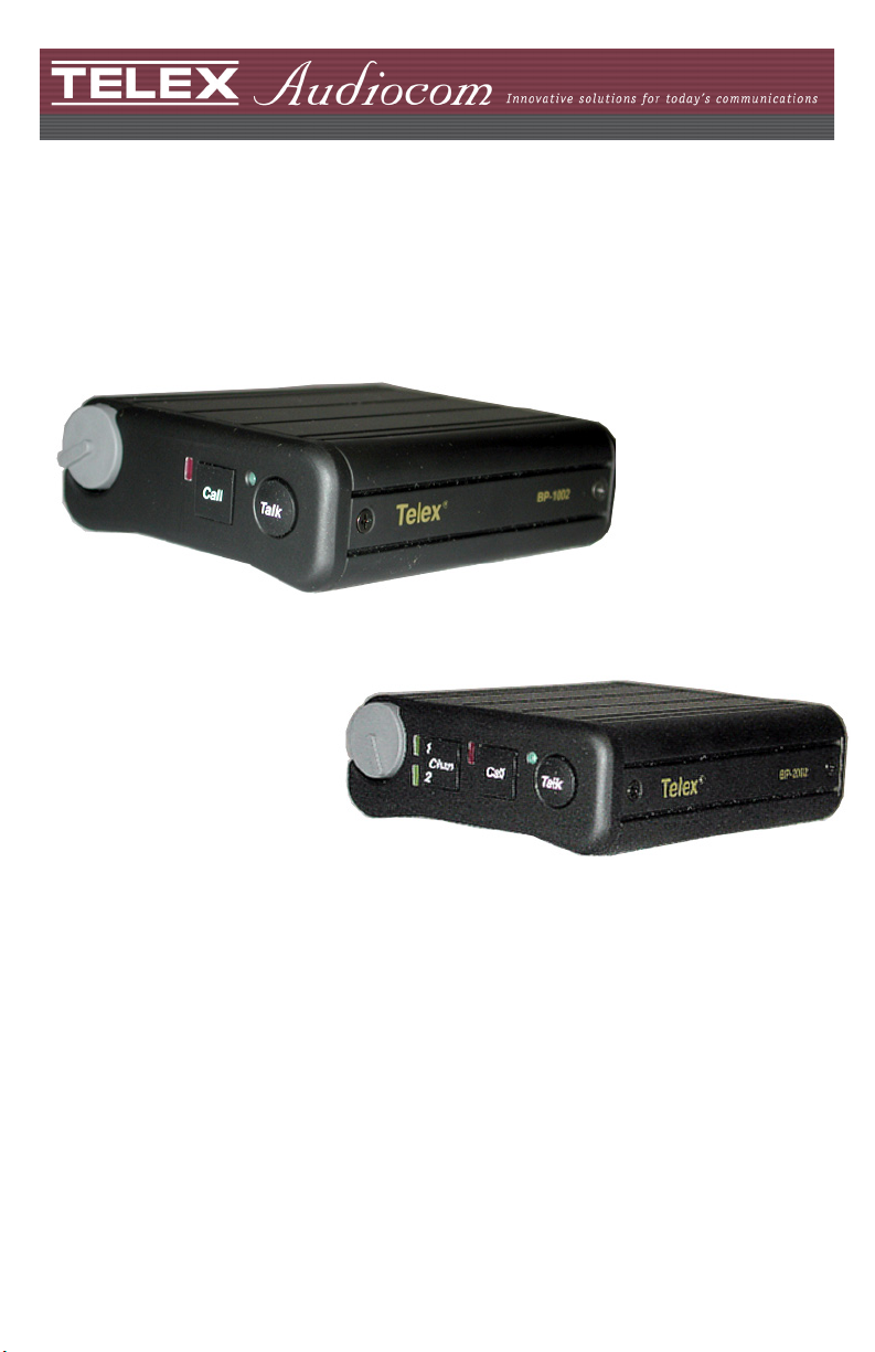
BP-1002 / BP-2002 Beltpacks
Audiocom Intercom Systems
93507740000 Rev L September/2010
Page 2
Audiocom Intercom Systems
PROPRIETARY NOTICE
The product information and design disclosed herein were
originated by and are the property of Bosch Security
Systems, Inc. Bosch reserves all patent, proprietary design,
manufacturing, reproduction, use and sales rights thereto,
and to any article disclosed therein, except to the extent
rights are expressly granted to others.
COPYRIGHT NOTICE
Copyright 2010 by Bosch Security Systems, Inc. All rights
reserved. Reproduction, in whole or in part, without prior
written permission from Bosch is prohibited.
WARRANTY AND SERVICE INFORMATION
For warranty and service information, refer to the
appropriate web site below:
RTS...................................www.rtsintercoms.com/warranty
RTSTW......................................... www.rtstw.com/warranty
AudioCom .................... www.telexaudiocom.com/warranty
RadioCom......................www.telexradiocom.com/warranty
Headsets.................... www.intercomheadsets.com/warranty
CUSTOMER SUPPORT
Technical questions should be directed to:
Customer Service Department
Bosch Security Systems, Inc.
12000 Portland Avenue South
Burnsville, MN 55337 USA
Telephone: 877-863-4169
Fax: 800-323-0498
Info@rtsintercoms.com
Technical Questions EMEA
Bosch Security Systems Technical Support EMEA
http://www.rtsintercoms.com/contact_main.php
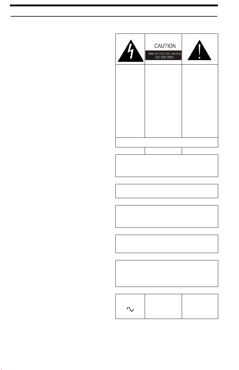
THE
LIGHTNING
FLASH AND
ARROWHEA
D WITHIN
THE
TRIANGLE
IS A
WARNING
SIGN
ALERTING
YOU OF
“DANGEROU
S VOLTAGE”
INSIDE THE
PRODUCT.
SEE MARKING ON BOTTOM/BACK OF PRODUCT
WARNING: APPARATUS SHALL NOT BE EXPOSED TO
DRIPPING OR SPLASHING AND NO OBJECTS FILLED
WITH LIQUIDS, SUCH AS VASES, SHALL BE PLACED ON
THE APPARATUS.
WARNING: THE MAIN POWER PLUG MUST REMAIN
READILY OPERABLE
CAUTION: TO REDUCE THE RISK OF ELECTRIC SHOCK,
GROUNDING OF THE CENTER PIN OF THIS PLUG MUST
BE
MAINTAINED.
WARNING: TO REDUCE THE RISK OF FIRE OR ELECTRIC
SHOCK, DO NOT EXPOSE THIS APPRATUS TO RAIN OR
MOISTURE.
WARNING: TO PREVENT INJURY, THIS APPARATUS
MUST BE SECURELY ATTACHED TO THE FLOOR/WALL/
RACK IN
ACCORDANCE WITH THE INSTALLATION INSTRUCTIONS.
CAUTION: TO
REDUCE THE
RISK OF
ELECTRIC
SHOCK, DO NOT
REMOVE COVER.
NO USERSERVICABLE
PARTS INSIDE.
REFER
SERVICING TO
QUALIFIED
SERVICE
PERSONNEL.
THE
EXCLAMATION
POINT WITHIN
THE TRIANGLE
IS A WARNING
SIGN ALERTING
YOU OF
IMPORTANT
INSTRUCTIONS
ACCOMPANYIN
G THE PRODUCT
This product is AC
only.
2
Page 3

Audiocom Intercom Systems
1. Read these instructions.
2. Keep these instructions.
3. Heed all warnings.
4. Follow all instructions.
5. Do not use this apparatus near water.
6. Clean only with dry cloth.
7. Do not block any ventilation openings. Install in accordance with the manufacturer’s instructions.
8. Do not install near any heat sources such as radiators, heat registers, stoves, or other apparatus (including amplifiers) that produce heat.
9. Do not defeat the safety purpose of the polarized or grounding-type plug. A polarized plug
has two blades with one wider than the other. A grounding type plug has two blades and a
third grounding prong. The wide blade or the third prong are provided for your safety. If the
provided plug does not fit into your outlet, consult an electrician for replacement of the
obsolete outlet.
10. Protect the power cord from being walked on or pinched particularly at plugs, convenience receptacles, and the point where they exit from the apparatus.
11. Only use attachments/accessories specified by the manufacturer.
12. Use only with the cart, stand, tripod, bracket, or table specified by the manufacturer, or sold with the apparatus. When a cart is used, use caution when moving the cart/apparatus combination to avoid injury from tip-over.
13. Unplug this apparatus during lightning storms or when unused for long periods of time.
14. Refer all servicing to qualified service personnel. Servicing is required when the apparatus
has been damaged in any way, such as power-supply cord or plug is damaged, liquid has
been spilled or objects have fallen into the apparatus, the apparatus has been exposed to rain
or moisture, does not operate normally, or has been dropped.
Important Safety Instructions
FCC STATEMENT
This equipment uses, and can radiate radio
frequency energy that may cause interference to
radio communication if not installed in accordance
with this manual. The equipment has been tested
and found to comply with the limits of a Class A
computing device pursuant to Subpart J, Part 15 of
FCC Rules which are designed to provide
reasonable protection against such interference
when operated in a commercial environment.
Operation of this equipment in a residential area
may cause interference which the user (at his own
expense) will be required to correct.
This product meets
Electromagnetic Compatibility
Directive 89/336/EEC
3
Page 4

Audiocom Intercom Systems
4
Page 5

Table
of
Contents
INTRODUCTION ......................................................................3
External Connections and Controls .................................................5
OPERATION .............................................................................7
System Power .................................................................................. 7
Initial BP-1002/2002 Setup ............................................................. 7
Operating Modes .............................................................................. 8
Changing Modes of Operation ............................................................... 8
Internal Switches, Jumpers, and Adjustments ................................. 9
Sidetone Adjustment (R145) .................................................................. 9
Mic Gain Adjustment (R156) ............................................................... 10
Clear-Com Setup .................................................................................. 10
Connector Pin Configurations ....................................................... 11
Specifications ................................................................................. 12
Optional Football Modifications .................................................... 13
General Description .............................................................................. 13
Eliminating Mic Kill and Call Signal ................................................... 13
Restoring Mic Kill and Call Signal ...................................................... 13
Notes .............................................................................................. 15
Page 6

Page 7

CHAPTER 1
Introduction
WARNING: If you have a BP-1002/2002 with a 9030-7740-XXX circuit board,
you must obtain revision H of this user manual.
The Audiocom BP-1002 and BP-2002 are microprocessor controlled 1- and
2-channel intercom beltpacks. An internal switch and jumper setting allows the units
to be used with Clear-Com components, if desired. Other internal switch and jumper
settings allow the unit to be uniquely configured to the operator’s requirements.
3
Page 8

Introduction
FIGURE 1. BP-2002 & BP-1002 Connections and Controls
4
Page 9

Introduction
External Connections and Controls
NOTE: The numbers refer to the callouts in Figure 1.
1. Volume Control: The Volume Control is used to adjust the
headset listen level.
2. Chan Button and Indicators: The Chan button (only on the BP-2002)
allows the user to select which intercom
channel is active. Press the Chan button to
change the channel selection. The yellow
indicator next the channel number lights
to show the active channel.
3. Call Button and Indicator: The Call function allows the user to send
or receive signals to other devices on the
intercom channel selected. The call
button operates in two (2) ways:
• Call Receive - When there is an
incoming call signal, the indicator is
red. (If Audible Call Alert is enabled,
incoming calls cause beeps in the
headset.) On the BP-2002, calls can be
sent on the selected channel only.
• Call Send - To send a call signal to all
stations on a channel, press and hold
the Call button until a verbal response
is received. The indicator will glow
red. On the BP-2002, calls can be sent
on the selected channel only.
4. Talk Button and Indicator: The Talk button activates the headset
microphone and operates in two (2) ways:
• Latched Mode - Tap the button once to
talk. The indicator glows green. Tap
the button again when finished with a
conversation.
• Momentary Mode - Press and hold the
button to talk momentarily. Release the
button when finished talking.
NOTE: On the BP-2002, if no headset is connected, when the Talk button is
pressed, the Talk button has the same function as the Chan button.
5
Page 10

Introduction
5. Sidetone Control: When using a headset, this control adjust
your own voice level heard in the
headphones. To adjust the level, tap the
Talk button once to turn on the headset
microphone. Then, use a small Phillips
head screwdriver to increase or decrease
your voice level while talking into the
microphone. (This control is accessible
by removing one (1) screw in the belt
clip.)
6. Headset Connector: This connector accepts a 4-wire Bosch
boom microphone headset.
7. Intercom Channel Connectors: On the BP-2002, intercom channels are
connected via a pair of 6-pin connectors
(one male and one female). The male and
female connectors are wired together in
parallel, providing a loop-through at each
connector pin. Use one connector to
connect to the intercom channel. Use the
other connector to daisy chain a cable to
the next beltpack or other station on the
channel.
Local Power Input - Normally, the
BP-2002 is power from the intercom
system and turns on with the
intercom system. The BP-2002
beltpack may also be powered from
an optional power supply
(21-30 VDC) connected between
pin 2 (+) and pin 1 (-) of the intercom
channel connector.
8. Intercom Channel Connectors On the BP-1002, the intercom channel is
connected via a pair of 3-pin connectors
(one male and one female). The male and
female connectors are wired together in
parallel, providing a loop through at each
connector pin. Use one connector to
connect to the intercom channel. Use the
other connector to daisy chain a cable to
the next beltpack or other station on the
channel.
6
Page 11

CHAPTER 2
Operation
System Power
The BP-1002/2002 beltpack receives power externally in one of two ways:
• The intercom channel
• The local power (pin 2) of the intercom channel connector
(BP-2002 only)
Both the BP-1002 and BP-2002 pass system power through to subsequent beltpacks
that are daisy chained together.
Initial BP-1002/2002 Setup
The channel termination is initially set for balanced operation, which is compatible
with other Audiocom equipment. If the unit is going to be connected to Clear-Com
equipment, one switch must be changed as described in the second on Clear-Com
setup in this manual.
The headset microphone type is auto-sensing, which means it automatically
determines if an Electret or Dynamic headset is attached to the unit.
7
Page 12

Operation
Operating Modes
The microprocessor within the BP-1002/2002 controls four (4) modes of operation
that affect the Microphone Kill and Audible Call Alert features. These modes can be
seen in Table X on page X.
Changing Modes of Operation
Perform the following steps to change the mode of operation.
NOTE: Both the Talk and Call indicators should be off and the headset should
be connected.
1. Press and hold the Talk key, and then press and hold the Call key.
2. Release both keys.
The Call indicator glows red. (The number of beeps heard in the headset
indicates the current mode of operation.)
3. Press the Call key to change to the next mode of operation.
Each press of the Call key causes the BP-1002/2002 to change the next mode
of operation.
4. When the desired mode is reached, press the Talk key to select that mode and
exit the mode changing function.
Beeps are heard in the headset when the mode changing function is exited.
The number of beeps hears indicates the selected mode of operation.
NOTE: Each time the intercom system power is turned on, the beltpack
resets to the default mode of operation (mode 2).
TABL E 1 . Modes of Operation
Mode (beeps) Mic Kill Audible Call Alert
1 Disabled Disabled
2 (default) Enabled Disabled
3 Disabled Enabled
4 Enabled Enabled
8
Page 13

Operation
Internal Switches, Jumpers, and Adjustments
There are several switches, jumpers, and adjustments that affect operation. These are
described below. To gain access to the switches, jumpers, and adjustments, disconnect
all power and line connections. Remove two (2) screws from the top of each side and
two (2) from the bottom of each side. Switch, jumper and adjustment locations are
shown in Figure 2.
FIGURE 2. Internal Switches, Jumpers, and Adjustments
NOTE: Figure 2 shows a BP-2002 with the switches and jumpers in their factory
default positions. SW5 does not exist on the BP-1002 board.
The Sidetone and Mic Gain adjustment are also accessible behind the screw that holds
the belt clip (callout 5 in Figure 1).
The functions of the internal switches are jumpers are described in Table 2 on
page 10.
Sidetone Adjustment (R145)
The sidetone adjustment is accessible either internally (refer to Figure 3) or by
removing the belt clip mounting screw (callout 5 in Figure 1).
9
Page 14

Operation
To adjust the level of your own voice heard in the headphones, tap the Talk button
once to turn on the headset microphone. Then, use a small Phillips head screwdriver
to increase or decrease your voice level while talking into the microphone.
Mic Gain Adjustment (R156)
The Mic Gain Adjustment is accessible internally on the board (R156) (refer to Figure
3) or by removing the belt clip mounting screw (callout 5 in Figure 1).
To adjust mic gain, do the following:
> Using a Phillips head screwdriver, turn the Mic Gain pot clockwise to
increase the gain (or counter-clockwise to decrease the gain).
Clear-Com Setup
Make the following switch and jumper changes when the beltpack is used with ClearCom equipment
BP-1002/2002
> SW1 must be placed in the UNBAL position.
TABL E 2 . Internal Switches and Jumpers
Jumper/
Switch
Number
Power Select
JP1 and JP2
SW1
JP3 Must be left on default
JP5 Pins 1 & 2 shorted
Channel one power: pins 2 & 3 shorted
(On BP-1002, pins 2 & 3 are always shorted)
Channel two power: pins 1 & 2 are shorted
Clear-Com/Audiocom
Unbalanced/Balanced Line
Jumper or Switch Function
10
Default
Setting
Pins 2 & 3
are shorted
BAL
Pins 2 & 3
shorted
Pins 1 & 2
shorted
Page 15

Connector Pin Configurations
Headset Connector
Type: XLR-4M (Callout in Figure 1)
Pin 1 Headset Microphone Low
Pin 2 Headset Microphone High
Pin 3 Headphone High
Pin 4 Headphone Low
Intercom Channel Connectors
BP-1002
Type: One XLR-3M and XLR3-F pair (callout 8 in Figure 1)
Audiocom Mode (internal switch SW1 set to BAL position)
Pin 1 Common
Pin 2 Intercom audio/call low and +24VDC input
Pin 3 Intercom audio/call high and +24VDC input
Clear-Com Mode (Internal switch SW1 set to UNBAL)
Pin 1 Common
Pin 2 +30VDC input
Pin 3 Intercom audio/call signal
BP-2002
Type: One XLR-6M and XLR-6F pair (callout 7 in Figure 1)
Audiocom Mode (internal switch SW1 set to BAL position)
Pin 1 Common
Pin 2 Local Power (21-30VDC)
Pin 3 Channel A intercom audio/call low and +24VDC input
Pin 4 Channel A intercom audio/call high and +24VDC input
Pin 5 Channel B intercom audio/call low and +24VDC input
Pin 6 Channel B intercom audio/call high and +24VDC input
Clear-Com Mode (internal switch SW1 set to UNBAL position)
Pin 1 Common
Pin 2 Local Power (21-30VDC)
Pin 3 Channel A +30VDC input
Pin 4 Channel A intercom audio/call signal
Pin 5 Channel B +30VDC input
Pin 6 Channel B intercom audio/call signal
Operation
11
Page 16

Operation
Specifications
General
Power Requirements:
Channel Supplied: 24VDC nominal, 40 to 100mA
Local Power: 24VDC nominal (21 to 30VDC), 40 to 100mA
Environmental Requirements:
Storage: -20°C to 80°C; 0% to 95% humidity, non-condensing
Operating: -15°C to 60°C; 0% to 95% humidity, non-condensing
Dimensions: 5.0” (127mm) H x 3.5” (88.9mm) W x 1.8” (45.7mm) D
Weight: 13oz. (0.36kg)
Interface Requirements
Headset:
1000-3000 Ohm electret microphone
50-200 Ohm dynamic microphone
150-600 Ohm headphones
Input Level:
4mV
RMS (nominal)
Balanced Intercom Channel:
Output Level: 1 V
Terminating Impedance: 300 Ohm ±10%
Bridging Impedance: greater than 10,000 Ohm
Call Signaling
Send: 20kHz ±100Hz, >500mV
Receive: 20kHz ±800Hz, 100mVRMS (minimum)
Mic-Off Frequency
Detect: 24kHz ±800Hz, 100mV
Noise Contribution: less than -60dBu on the line
Total Harmonic Distortion: less than 1% at channel output for normal input
Unbalanced Intercom Channel:
Output Level: 775mV
Terminating Impedance: 200 Ohm ±10%
Bridging Impedance: greater than 10,000 Ohm
Call Signaling
Send: 12 ±3VDC on the line
Receive: 4 -15VDC from the line
Total Harmonic Distortion: less than 1% at channel output for normal input
RMS nominal
RMS
RMS (minimum)
RMS ±10%
12
Page 17

Operation
Headphone Amplifier
Maximum Output:
3.5 ±10% Vrms into 150Ω headset
Frequency Response:
200Hz to 8kHz ±2dB
Audible Alert:
1kHz, at the headset
Total Harmonic Distortion:
Less than 1% at less than 3.25V
Sidetone:
17dB minimum range, adjustable
RMS into 150Ω headset
Optional Football Modifications
General Description
In Audiocom Intercom Systems, the Mic Kill feature is used to turn off any activated
microphone on a selected channel. The Mic Kill feature is activated when the
beltpack receives a 24kHz signal from the channel. In some applications, the Mic Kill
and Call Signal features are not desired and need to be disabled.
Eliminating Mic Kill and Call Signal
CAUTION: To prevent damage to the equipment, these modifications should only be
made by qualified technicians.
If desired, the Mic Kill and Call Signal features can be disabled in the BP-1002/2002,
by removing a surface mounted capacitor from the printed circuit board.
To remove the capacitor, do the following:
1. Before making changes to the printed circuit board, disconnect all power and
line connections from the beltpack.
2. Refer to Figure 3, and locate C61 on the underside of the printed circuit
board.
3. Remove capacitor C61 from the printed circuit board.
Restoring Mic Kill and Call Signal
13
Page 18

Operation
To restore the Mic Kill and Call Signal feature, replace C61 with Bosch part number
F01U143777, 1500pF, 50V capacitor.
FIGURE 3. Printed Circuit Board
14
Page 19

Notes
Operation
15
Page 20

 Loading...