

Page 1
9350-7532-000 Rev A October 30, 2003
1
Page 2

2
Page 3

3
Page 4

This Page left Intentionally Blank
4
Page 5

Proprietary Notice
The RTS product information and design disclosed herein were originated by and are the property of Telex
Communications, Inc. Telex reserves all patent, proprietary design, manufacturing, reproduction, use and sales rights
thereto, and to any article disclosed therein, except to the extent rights are expressly granted to others.
Copyright Notice
Copyright 2003 by Telex Communications, Inc. All rights reserved. Reproduction in whole or in part without prior
written permission from Telex is prohibited.
UNPACKING AND INSPECTION
Immediately upon receipt of the equipment, inspect the shipping container and the contents carefully for any
discrepancies or damage. Should there be any, notify the freight company and the dealer at once.
WARRANTY INFORMATION
RTS products are warranted by Telex Communications, Inc. to be free from defects in materials and workmanship for
a period of three years from the date of sale. The sole obligation of Telex during the warranty period is to provide,
without charge, parts and labor necessary to remedy covered defects appearing in products returned prepaid to
Telex. This warranty does not cover any defect, malfunction or failure caused beyond the control of Telex, including
unreasonable or negligent operation, abuse, accident, failure to follow instructions in the Service Manual or the User
Manual, defective or improper associated equipment, attempts at modification and repair not authorized by Telex,
and shipping damage. Products with their serial numbers removed or effaced are not covered by this warranty. To
obtain warranty service, follow the procedures entitled “Procedure For Returns” and “Shipping to Manufacturer for
Repair or Adjustment”. This warranty is the sole and exclusive express warranty given with respect to RTS products.
It is the responsibility of the user to determine before purchase that this product is suitable for the user’s intended
purpose.
ANY AND ALL IMPLIED WARRANTIES, INCLUDING THE IMPLIED WARRANTY OF MERCHANTABILITY ARE
LIMITED TO THE DURATION OF THIS EXPRESS LIMITED WARRANTY. NEITHER TELEX NOR THE DEALER
WHO SELLS
RTS PRODUCTS IS LIABLE FOR INCIDENTAL OR CONSEQUENTIAL DAMAGES OF ANY KIND.
CUSTOMER SUPPORT
Technical questions should be directed to:
Customer Service Department
RTS/Telex
12000 Portland Avenue South
Burnsville, MN 55337 U.S.A.
Telephone: (800) 392-3497
Fax: (800) 323-0498
5
Page 6

Table of Contents
Introduction....................................................................................8
Features..............................................................................8
AZedit Description .............................................................8
Getting Started...................................................................9
Intercom Configuration Description................................10
Connecting and Disconnecting......................................10
Master Controller Intercom Configuration......................13
Procedure to change the master controller intercom
configuration settings.....................................................14
Setup File Configuration Settings ..................................14
Keypanels and Ports........................................................16
Right-Click Guide to the Keypanel/Port main screen....21
Keypanel/Ports Configuration.........................................33
Right-Click Guide to the Keypanel/Port Configuration
Setup screen.....................................................................36
Keypanel / Ports Configuration.......................................37
Right-Click Guide to the Keypanel/Port Configuration
Advanced screen..............................................................40
Gain Setup for Output Port..............................................43
Right-Click Guide to the Gain Setup to the Output Port
screen...........................................................................46
Port Alpha.........................................................................47
Right-Click Guide to the Alpha screen...........................48
Party Lines........................................................................52
Right Click Guide to the Party Lines Screen..................55
IFBs (Interrupted Fold Back)...........................................63
Right-Click Guide to the IFB Screen..............................65
Special Lists .....................................................................73
Right-click guide to the SL screen .................................75
GPI Out..............................................................................78
Right-Click Guide to the GPI Out screen .......................80
ISO.....................................................................................83
Right-Click Guide to the ISO screen..............................85
Right-Click Guide to the GPI Input Screen.....................89
UPL....................................................................................92
Right-Click Guide to the UPL Screen.............................94
Inter-panel Dim Tables...................................................105
Right-Click Guide to the Inter-panel Dim Tables..........107
XPT (Crosspoint)............................................................109
Gain.................................................................................112
Other Alphas...................................................................117
6
Page 7

Party Line Alphas........................................................118
IFB Alphas...................................................................119
Special List Alphas......................................................120
GPI Output Alphas.......................................................121
ISO Alphas..................................................................122
UPL Resource Alphas.................................................123
GPI Input Descriptions.................................................124
Inter-panel Dim Descriptions .......................................125
Common Tasks...............................................................126
Appendix A AZedit Keyboard Shortcuts.....................................134
Appendix B AZedit Quick Start..................................................139
Introduction................................................................................140
Getting Started for New Users.......................................140
Glossary of Terms......................................................................144
INDEX..............................................................................179
7
Page 8

Introduction
Intercom system configuration has never been easier with the advent of Telex's AZedit Intercom System Software.
AZedit is a Windows®-based, full-featured configuration software, providing online and offline configuration
capabilities. It gives you the ability to manage multiple intercom systems, assign and reassign users to different ports,
as well as dynamically add intercom hardware to your system setup without jumper changes, rewiring, or taking the
system offline. AZedit has the capability to load pre-set configuration files, which means configurations saved to a
disk can be uploaded to the "live" application at anytime without interruption. AZedit's online and offline configuration
capabilities allow you to make changes directly to the application or upload changes from a file created at an earlier
time.
Features
• PRINTING OF DESIGNATION STRIPS FOR ZEUS
FAMILY KEYPANELS: When printing designation
strips for keypanels, different dimensions for
the strip height and/ or center-key spacing are
used for the MKP-4, MKP-12, BKP-4, WKP-4,
and TKP-4. When a panel contains fewer than
16 keys, only the actual number of keys is
printed.
• ONLINE help: Updated online help file that
includes help for more items and problem fixes.
• UPL (USER PROGRAMMABLE LOGIC) CONTROL OF
IFB PROGRAM INPUT SUPPORT: UPL Control of
IFB Program Input allows a user to set the
output action of a UPL statement to change the
program input of an IFB while the UPL is
active. (This feature requires ADAM Master
Controller version 9.16.3 or DBX version
1.8.2).
• LOCAL STORAGE OF ADVANCED PARAMETERS: A
preference setting gives you the ability to store
Advanced Communications parameters locally,
so that when a "first birthday" occurs
connecting to the Intercom with AZedit will
automatically restore the advanced
communication settings.
• AZEDIT: AZedit combines both the ADAMedit and
ZEUSedit into one program to allow
communication with both ADAM and ZEUS
intercoms.
• MULTIPLE ALPHA SIZES: Permits keypanels with
different alpha sizes to exist on the same
intercom. The keypanel view automatically
changes alpha size to whatever type of keypanel
is active.
• ALPHA COUNTERS: Alpha counters permit the live
update of alphas as they are changed on local or
remote intercoms. Alpha counters auto-refresh
alpha changes.
Required firmware for Alpha Counters:
Adam Master Controller 9.16.0
Zeus Master Controller 3.1.0
Peripheral Controller 10.8.0
DBX 1.8.0
AIO Cards 10.2.0
• VOLUME DISPLAY: Keypanel view shows changed
and restricted status of volumes.
AZedit Description
AZedit is automatically configured to work on any Telex intercom system. This means that if you have an ADAM CS
intercom system, AZedit will display only resources available in your intercom system. On the other hand, if you have
a multi-frame ADAM intercom system, AZedit will still display all of the resources that are configured to be available in
your system.
8
Page 9
Getting Started
The AZedit software comes with either two 3.5" floppy disks or a CD, used to install the application onto a central
computer.
Minimum Requirements for Software Installation
• Pentium Processor
• 64 MB Ram
Note: The larger the intercom system the more RAM is required to run the software effectively.
For example, a seven-frame intercom system will require more RAM than a one-frame system.
• Microsoft® Internet Explorer 5.01 and higher or NT Service Pack 6.0
• Microsoft® Windows 98,NT, 2000, XP
AZedit Installation and Configuration
During installation, AZedit creates three subfolders within the application folder. These folders are named Firmware,
Logs, and Setups. The Firmware folder is the default folder where the application looks for firmware update files. The
Logs folder is the default location where the application saves log files. The Setups folder is the default location
where the application saves setup files. When you remove the application, these subfolders will not be removed.
To install AZedit, do the following,
1) Insert the AZedit CD into the into CDRom drive.
2) Take all the defaults, when prompted.
Uninstalling AZedit
To uninstall the software, use the Uninstall program supplied on the AZedit disk
Telex Communications
9
Page 10
Intercom Configuration Description
The intercom configuration is split into two groups: resources and options.
Resources are the number of intercom ports, party lines, etc. that are available.
Options describe such things as the number of talk levels for each talk key, or the number of setup pages for each
keypanel.
Some options slightly modify the operation of the intercom system. Some resource and option settings are limited by
the amount of available hardware. For example, in a Resource list, the number of Ports is limited to the number of
Audio I/O Cards in the intercom system. For other resources and options, the quantity is primarily limited by the
amount of available memory in the master controller. For example, a party line does not represent any hardware. It is
a definition of who is a member of the party line. However, each party line definition requires a certain amount of
master controller memory. Similarly, in the Options list, you can define 2-4 talk levels for all talk key assignments. The
more talk levels you define, the more master controller memory is required.
The intercom configuration is actually defined in 3 places within your intercom system: 1) within the master controller
2) within AZedit and 3) within each setup file. We normally recommend that you set the intercom configuration in the
master controller first, then apply these settings to AZedit afterward. Once you have done this, your setup files will
automatically be set to the same settings as the master controller and AZedit. The only time where a user might not
want all 3 settings to match is when configuring several independent intercom systems. The following paragraphs
contain a more detailed discussion of the 3 resource settings, and also how to manage the memory limitations.
Connecting and Disconnecting
There are three different modes AZedit can run in: File, Online, and Server mode.
File: File mode indicates the computer is not communicating with the intercom system. In this mode, the user can
create new setup files and open/edit new startup files, without the worry of interrupt users.
File mode is an excellent way to make a lot of changes that can be uploaded to the software at a later time when the
system has downtime or a low user base.
The changes made in File mode can be saved to a disk for upload at a later time. This is also a great way to have a
backup of changes made to the system.
Online: Online mode indicates the computer is communicating with the intercom system. Users can make changes to
the intercom configuration or manually send setup files to the intercom system.
Online mode is a quick and easy way to update or configure a few setup files or intercom configurations. When
complete, changes are uploaded straight to the system.
Note: Remember, if a lot of changes are necessary, it is best to use FILE mode because you can
upload your system changes when user traffic is lowest.
Server: Server mode indicates the computer is online and operating in Server mode. Users can view current intercom
system configurations, as well as intercom activity.
While in Server mode, no changes can be made. This is to eliminate any redundancy of effort by more than one user.
Telex Communications
10
Page 11

Connecting to ONLINE Mode from FILE Mode
Once you have finished making changes to the intercom system in File mode and have saved the changes to a disk,
you can connect to the intercom system from File mode to upload the changes.
To connect to ONLINE mode, do the following:
1. From the menu bar, select Online.
The Online drop-down menu appears.
2. From the drop-down menu, select Connect.
The word ONLINE appears in the lower right-hand corner of the main AZedit window.
To disconnect from ONLINE mode, do one of the following:
New
1. From the File menu, select New.
A message indicating, "you are about to exit ONLINE mode and edit a default intercom setup" appears.
2. Click OK to accept. Otherwise, click Cancel.
The word FILE appears in the lower right-hand corner of the main AZedit window.
Open
1. From the File menu, select Open.
A message indicating, "You are about to Exit ONLINE mode and open a file" appears.
2. Click OK to accept. Otherwise, click Cancel.
The Setups browse screen appears for you to choose the setup you would like to open. Also, the word FILE
appears in the lower right-hand corner of the main AZedit window.
Save
1. From the File menu, select Save.
The Save (Online setup) browse screen appears.
2. In the File Name text box, enter the setup file name to be saved (for example, Setup_9302003.adm).
3. Click Enter.
The Confirmation – ONLINE Save As screen appears.
4. When the option to stay online or enter file mode appears, select Enter FILE Mode. Otherwise, select
ONLINE.
5. Click Continue.
The upload of the setup file begins. You will see a status bar until it is finished uploading the data. Once the
file is uploaded the word FILE appears in the lower right-hand corner of the main AZedit window
Otherwise, click Cancel to cancel the upload and return to the main AZedit screen.
Connecting / Disconnecting – SERVER Mode
Following the status of the Intercom system is vital to effective and efficient operation. Server Mode allows the user to
monitor real-time intercom activity. Remember, changes to the Intercom system may not be made in SERVER Mode.
Note: You must be in ONLINE Mode before you can enter SERVER Mode.
Telex Communications
11
Page 12

To connect using SERVER Mode, do the following:
1. From the Online menu, select Server Mode.
A check mark appears next to Server Mode when it is active, the background in all fields turns purple, and
the word SERVER appears in the lower right corner of the main AZedit window.
To disconnect from SERVER Mode, do the following:
1. From the Online menu, click Server Mode.
The check mark is removed from Server Mode, the background in all fields returns to white, and the work
ONLINE appears in the lower right corner of the main AZedit window.
Trouble Connecting?
If you are having trouble connecting to the intercom system, try the following:
• Verify the power to the Intercom is ON.
• Verify the Intercom cable is properly connected to the PC. Refer to the cable information in your Intercom
System.
• Verify the COM Port and the Baud rate settings are correct
To adjust the Com port and Baud rate settings, do the following:
1. From the main menu select Options > Communications.
The Communications screen appears.
2. Verify or select the proper settings.
3. Click OK.
The Communications screen closes.
By default, AZedit is set for COM1 and 38,400 kbps (38.4 K baud). The baud rate set in AZedit MUST match the
baud rate setting of the master controllers in the ADAM or ADAM CS frame (DIP Switch #1). The 38,400 kbps setting
provides the fastest possible file uploads and downloads, but you may experience more communication errors
operating at this speed than at a lower baud rate setting. Cable lengths of 30-50 ft. (9-15 meters) have been used
successfully with the 38,400 kbps setting. However, this may not always work under all operating conditions.
If you suspect that you are experiencing communication problems operating at this speed, check the Master
Controller Status screen (Status>Master Controller Status). Rapid accumulation of communication errors on the
right side of that screen indicates a problem. In such cases, check cable construction or cable routing, or use a
shorter cable. You may have to try different scenarios before one will permit operation at 38,400 kbps.
Configure AZedit
To ensure the AZedit configuration matches your requirement for the intercom system configuration, make a
connection to your intercom system
This can be done from the menu Online and from the sub menu connect or by using the connect button on the
toolbar. If the toolbar is not displaying a purple plug on this icon the PC connection will need to be adjusted for a
suitable Com port setting and Baud rate, see, Trouble Connecting, page 7.
It is also possible the intercom system is not properly configured to show the correct amount of resources.
To verify that the basic intercom configuration is correct, do the following:
Telex Communications
12
Page 13

1. If you have been working on a setup file, perform a Save.
2. If you are not connected to the Intercom system, make a Connection. See Connecting – ONLINE mode,
page XXX.
3. From the Options menu, select Intercom Configuration.
A message indicating, "Warning! Changing these settings my cause a mismatch between ADAMedit and the
settings in the intercom" appears.
4. Click OK.
The Intercom Configuration screen appears.
5. Verify the current settings for Frames and Intercom Type match your intercom system. If needed, make
any changes to the Resource tab.
Note: From the Intercom Configuration screen, you may make other setting changes. However,
many users find the standard settings satisfactory. For more information about the Intercom
Configuration screen, see the AZedit Help.
Master Controller Intercom Configuration
In ADAM CS and ADAM intercom systems, the master controller configuration is the key to your intercom system,
because whatever is defined here is all that will be allowed for actual intercom operation. As you may have guessed,
it is possible to increase or decrease the quantities of some types of resources and options in the master controller to
free up memory for larger quantities of other resources. There are also reasons why you might want to reduce or
eliminate quantities of resources and options that are not required:
Advantages of reducing master controller intercom configuration settings
• The intercom system will power up faster with fewer resources.
• Less memory resources will be used in the system controller. For example, in larger, multi-frame intercom
systems, where the number of intercom ports can exceed several hundred, the configuration information
for the ports themselves will require a large portion of the system memory. In such cases, unused IFB's,
ISO's etc. can be removed from the resource configuration to make room for resources that are being
used.
• Scroll lists will be smaller (when viewing them both in AZedit or from a keypanel).
• AZedit will connect to the intercom system faster (fewer items to upload).
• AZedit will update faster (fewer items to query).
• Saving/Loading files will be faster (less data to upload, less data to save/load).
• Setup files will require less disk space with fewer resources.
• Checks for duplicate names (alphas) will be faster with fewer resources.
• Sending changes to the intercom system will be faster with fewer resources.
• You will not mistakenly configure resources that do not exist (i.e. using ports that do not have Audio I/O
Cards).
Disadvantages of reducing master controller intercom configuration settings
• If you add more hardware later (More Audio I/O Cards, for example) you will have to readjust your master
controller and AZedit configuration settings. Changing settings in the master controller can take up to 10
minutes. You may also have to reconfigure your setup files. This may require 2-3 minutes per file if you
have several files.
Telex Communications
13
Page 14
Procedure to change the master controller intercom configuration settings
I
AZedit Intercom Configuration Settings
Initially, AZedit defines the quantity for each resource and option. However, these quantities may be changed to fit
your intercom system.
To assure you are viewing the intercom configuration for the application, and not for a setup file or the master
controller, do the following:
If you have been working on a setup file in FILE mode, save any changes you have made. If you have been
working on the online setup file in ONLINE mode, send your changes to the intercom system.
1. From the File menu, select New, or click the New File button.
2. From the Options menu, select Intercom Configuration.
A message indicating, "Warning! Changing these settings my cause a mismatch between ADAMedit and
the settings in the intercom" appears.
3. Click OK.
The Intercom Configuration screen appears with Resource options showing.
Note: When you first install AZedit, it is set to the default resources for a 1-frame ADAM intercom
system. If you are using AZedit with an ADAM CS Intercom System, or with a multi-frame
ADAM Intercom System, be sure to make the necessary changes that reflect your intercom
system size.
Although you can change the AZedit resource settings at this time, we recommend that you
change the master controller configuration settings first, then select those settings as the
AZedit default settings when prompted to do so.
Setup File Configuration Settings
When a setup file is opened, the intercom configuration settings for that setup file are loaded. You can change the
intercom configuration to different settings other than the AZedit default settings.
The only time you might want to do this is when you are creating setup files for several different
intercom systems, each with its own set of resources. Usually, you create your setup files using the
default application resources.
To create a new file with either the default or the intercom configuration settings, do the following:
1. From the File menu, select New.
One of two messages may occur:
A message indicating, "The current intercom configuration is different than the default configuration. Before
opening a file, or creating a new file you must select which configuration to use:" appears.
Note: If you are not prompted, the default settings are already selected.
A message indicating, "You are about to exit ONLINE mode and edit a default intercom setup" appears.
2. If prompted, choose to use either the default configuration or the current configuration .
3. Click OK.
The word FILE appears in the lower right-hand corner of the main AZedit window.
Note: You may have previously created AZedit setup files that you want to reconfigure to match the
current AZedit default settings, or some other settings. For further information, see Changing
the Configuration Settings in Setup files.
Telex Communications
14
Page 15

Screen Descriptions
Telex Communications
15
Page 16
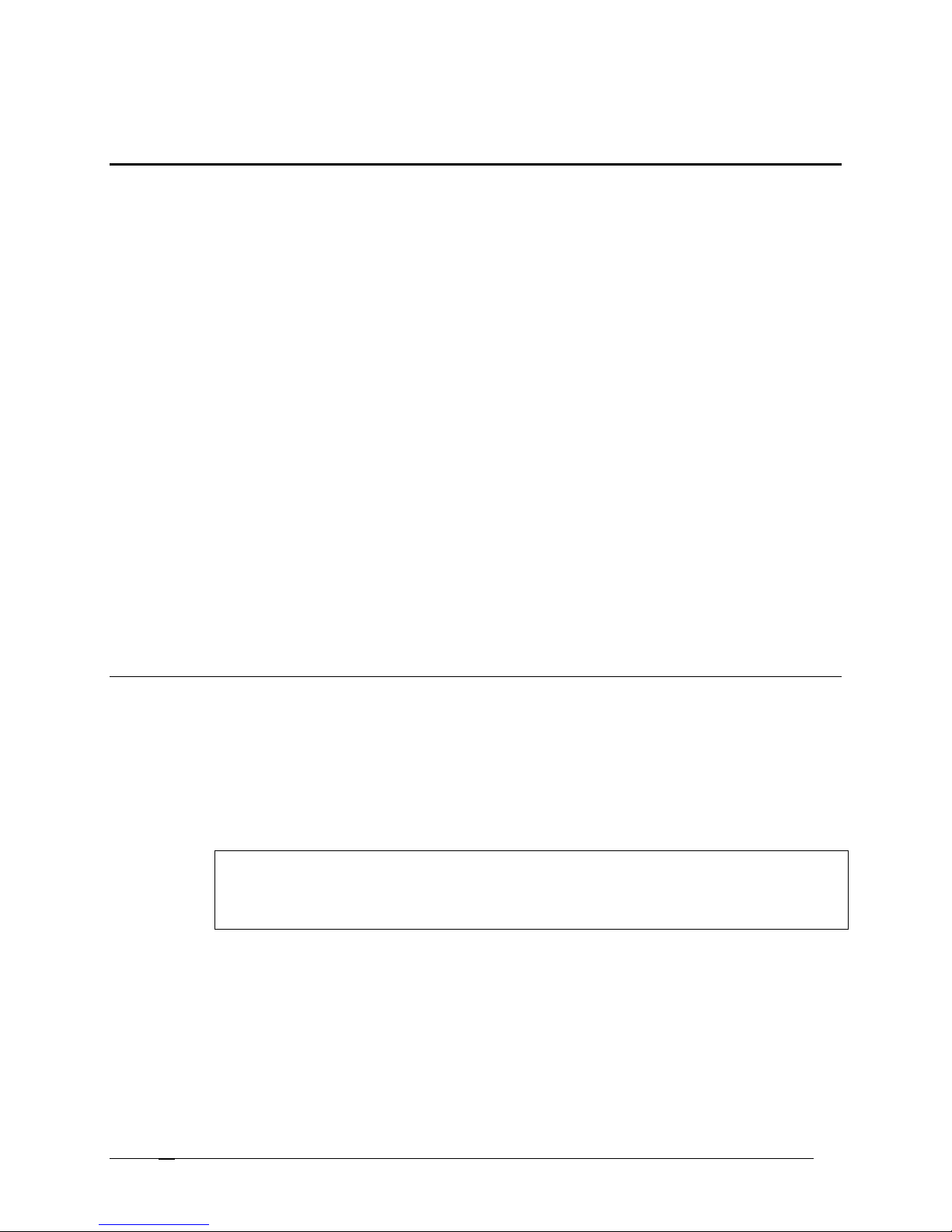
Keypanels and Ports
The Keypanel/Ports screen displays essential keypanel information, such as Port numbers, Keypanel and Port
Settings, Port Status, Key Assignments, etc.:
KEYPANEL SETUP: Use this screen whenever you want to connect a keypanel to a particular intercom port and then
set up that keypanel. Keypanel setup includes assigning the keys and setting other keypanel options.
NON-KEYPANEL USAGE OF A PORT: Even if you are not using a keypanel at a port, there may still be a few items that
you will want to configure, like belt pack systems, fiber devices, 2-way radios, PA Systems, Telephone Hybrids,
etc… Basically, anything that would be a non-data device.
VIEW KEYPANEL ACTIVITY: View keypanel activity, such as key activations, during operation in ONLINE or SERVER
mode.
GPI INPUT ASSIGNMENT: Use GPI inputs to simulate keypanel keys even when no keypanel is connected at an
intercom port. Use GPI Input setup to define which "key" to activate at a specific port. Then, use the keypanel setup
to select the port and assign the "key".
Zeus, ADAM and ADAM CS intercom systems have a General Purpose Interface port (GPI). The GPI port has 8
control outputs (also referred to as Relays in AZedit) and 8 control inputs located:
• Zeus: Located on Zeus Back panel, J27
• ADAM: Located on XCP-ADAM-MC Master Controller Breakout Panel, J11
• ADAM CS: Located on ADAM CS back panel, J903
Additionally, all of these intercom systems can connect to one or more UIO-256 Universal Input / Output frames,
each of which provides 16 control outputs and 16 control inputs.
General Keypanel Setup Procedure
AZedit helps configure and manage keypanels in the intercom system. Being thorough when setting up the keypanel
is essential in organizing and effectively managing the intercom system through AZedit.
To setup a keypanel in AZedit, do the following:
1. Open AZedit.
2. In the Port field, enter the port number you want to assign a keypanel. (You can also select a port alpha
from the Alpha drop down list.)
Note: If all key assignments are disabled (grayed out) on the selected intercom port, and "Trunk
Port" displays at the top of the window, the port is reserved for trunking. This means it
cannot be used for any other purpose. To reclaim the port, run CSTrunk and remove the
trunking allocation.
3. Click Edit.
The Keypanel/Port Configuration screen appears.
4. Verify or make changes to the various keypanel properties. For more information on the keypanel properties,
see Keypanel / Ports Configuration.
Setup Tab: contains basic keypanel configuration options.
Advanced Tab: contains more advanced configuration options
Telex Communications
16
Page 17
5. Click OK.
For more information on changing Alpha Names, see
Changing
The changes you made are applied to the program and the Keypanel / Port Configuration screen closes.
Note: While editing the Setup and Advanced tabs, you can click Apply at any time to apply the
changes without closing the screen. This gives you the freedom to make more changes, if
needed.
Screen Items
Screen Item Field Type Description
Port text field
The Port field displays the identification numbers assigned to
individual channels to which devices are connected. Intercom
ports have identification numbers 1, 2 etc. These numbers
cannot be changed and are not usually commonly referred to by
intercom system users.
1. In the Port field, enter the port number for which you
want to configure.
Alpha drop-down list
Each intercom port also has a default name, called an "Alpha".
This name appears in the alphanumeric display on a keypanel
when you assign ports to keys for talking and listening.
The default alpha names are N001, N002 etc. These default
alpha names can be changed to names that are meaningful to
keypanel operators using Port Alpha
Telex Communications
17
Page 18

Screen Item Field Type Description
keypanels the user can currently view. The
user can select
Alpha Names.
1. From the Alpha drop down list, select the Alpha
assigned to the port.
Scroll Enable check boxes
The Scroll Enable check box controls who can view destinations
in scroll lists and assign those destinations to keypanel keys.
Scroll lists are lists of names (alphas) for intercom ports. You use
these scroll lists in AZedit when assigning keys on keypanels.
Scroll enable check boxes appear in the setup views for the
following destination types: intercom ports, party lines, IFB's,
Special Lists, GPI Outputs, UPL Resources, and ISO's.
Keypanel operators can also use these scroll lists at their
keypanels to assign keys. If your intercom system is part of a
larger trunked* intercom system, AZedit operators in remote
intercom systems, as well as keypanel operators in remote
intercom systems can use scroll lists to assign destinations in
your intercom system to keys in their intercom system. You can
control access to scroll lists, and therefore control the ability of
other people to assign keys, by changing the Scroll Enable
parameter.
When you are using AZedit within your own intercom system,
you always have access to complete scroll lists. However,
access for everyone else is controlled as follows:
Local: If Local is checked, any keypanel operator in your
intercom system that has a programmable keypanel can find the
destination name in a scroll list and assign it to a key. If you
remove this check mark and send the change to the intercom
system, keypanel operators will not see the destination name in
their scroll lists, and therefore, will not be able to assign it to a
key. They will also not be able to assign it using keypad numeric
entry (KP9X series keypanels). And, if the destination name
appears in any display on their keypanel, they will not be able to
copy it to any other key.
Trunk: The Trunk check box is only selectable if trunking has
been activated. If you place a check mark here, any keypanel
operator in a remote intercom system that has a programmable
keypanel can view the destination in a scroll list and assign it to a
key on their keypanel. If you remove this check mark and send
the change to the intercom system, remote keypanel operators
will not be able to view the destination or assign it to a key.
AZedit: This item is only selectable if trunking has been
activated. If you place a check mark here, an AZedit user in a
remote intercom system will be able to view the destination in a
scroll list and assign that destination to keypanel keys in the
remote intercom system. If you do not want remote AZedit users
to have access, remove the check mark and send the change to
the intercom system.
LCP-102: This item appears only in the Keypanels/Ports main
screen. If this item is enabled and checked, the intercom port will
be displayed in the IFB input scroll list of an LCP-102 operating
in PAP mode. This means the port can be selected as the
program source for an IFB input.
In the Scroll Enable field, select one or more of the following,
Local, Trunk, AZedit, or LCP-102.
Keypanel /Port Settings drop-down list
The Keypanel/Port drop down list displays the default page of
Telex Communications
18
Page 19
Screen Item Field Type Description
2. Select the relevant
D
check box to disable the key
different pages to edit page setups.
1. From the Keypanel/Port Settings drop down list,
select the keypanel type you are configuring.
Edit button
Use the Edit button to open the Keypanel/Port Configuration
screen.
For more information on the Keypanel Port Configuration screen,
see Keypanel Port Configuration.
Gain Setup for Output
Port
button
Opens the Gain Setup for Output Port screen
1. Click the Gain Setup button.
The Gain Setup for Output Port screen appears.
For more information on Gain Setup, see Gain Setup for Output
Port.
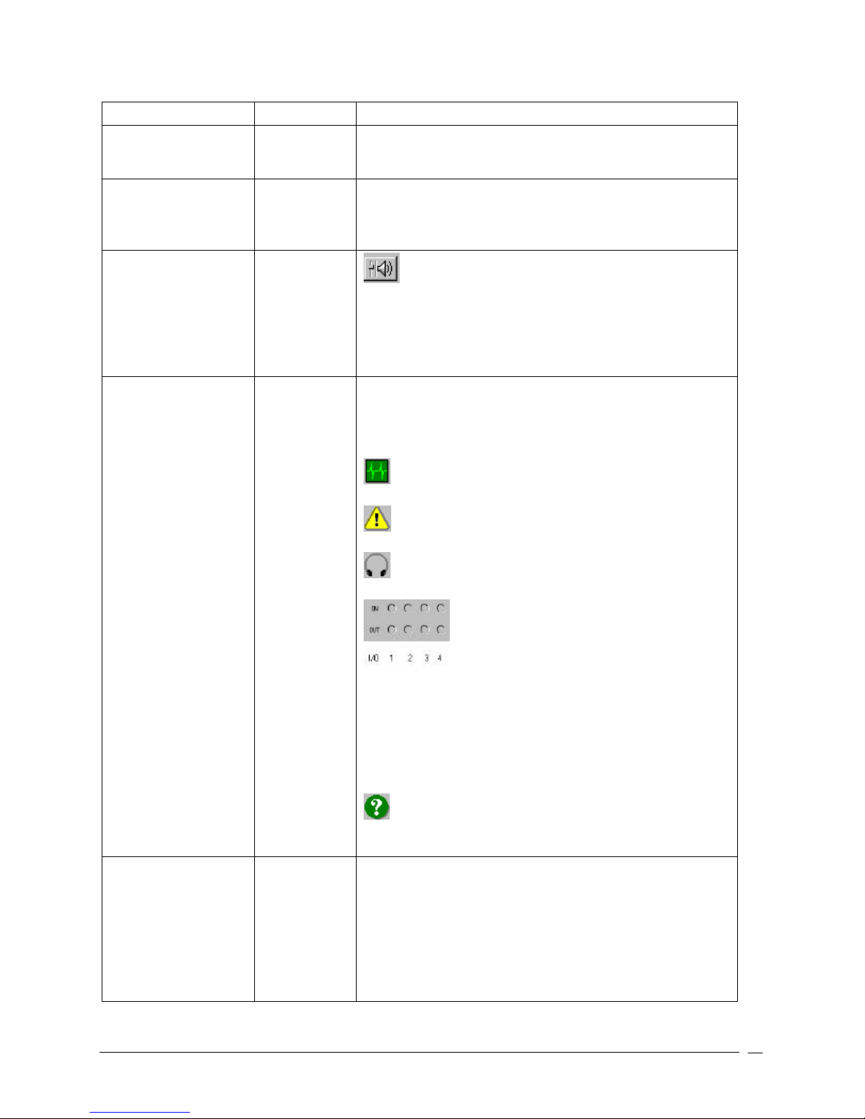
Port Status icon display
The following informational icons are displayed in the Port
Status group (located in the upper-right corner of the Keypanels
/ Ports screen): Most of these icons are activated based on
keypanel features detected by the intercom system master
controller.
Heartbeat Icon: Indicates a data device (keypanel, TIF, or
Camera Delegate Panel) is connected to the intercom port.
Listen Keys check box and
text field
Warning Icon: Indicates the intercom port is defined as an
IFB output (in the IFB Setup screen).
Headset Icon: Indicates the connected keypanel has a
headset selected.
LED Icons: Indicate the on/off state of any local
GPI inputs and outputs. These indicators function only when a
keypanel with a local GPI port is connected, and the operation is
controlled by UPL
Green = ON (Asserted)
Red = OFF (Inhibited)
Gray = None
IN = GPI Input
OUT = GPI Output
Question Mark Icon: Indicates the keypanel type selected
(with the Edit button) does not match what is reported by the
intercom.
The Listen keys are assigned different ports or alphas. These
alphas can only listen on these keys.
Use the D and/or R check box to either latch disable or restrict
the alpha assigned to that key.
1. In the Listen Key 1 text field, enter the alpha or port
number you wish to assign to the key.
Telex Communications
19
Page 20

Screen Item Field Type Description
latching function of the alpha or port number assigned
to the corresponding key.
3. Select the relevant R check box to restrict the alpha or
port number assigned to that corresponding key
Repeat this step to assign alphas or port numbers to
the rest of the listen key text fields.
Note: When a talk or listen key is on, a red dot will appear above
the key'.
Talk Keys check box and
text field
The Talk keys are assigned to different ports or alphas. These
alphas can only talk on these keys.
Use the D and/or R check box to either latch disable or restrict
the alpha assigned to that key.
In the Talk Key 1 text field, enter the alpha or port number you
wish to assign to the key.
Select the relevant D check box to latch disable the alpha or port
number assigned to the corresponding key.
Select the relevant R check box to restrict the alpha or port
number assigned to the corresponding key
Repeat this step to assign alphas or port numbers to the rest of
the listen key text fields.
Note: When a talk or listen key is on, a red dot will appear above
the key.
Mode display field
The Mode display field shows what mode AZedit is running in.
There are three modes AZedit can operate:
Online: In Online mode, the configuration computer is connected
to the intercom system, and AZedit is communicating with the
intercom system. You can make changes to the intercom system
setup, such as changing key assignments, or setting up party
lines, etc. You can also view various types of intercom activities,
as well as check the status of various components of the
intercom system. When changes are made in Online mode, you
still need to send changes to the program for them to be
activated.
Server: In Server mode, AZedit acts like a file server, sending
setup files to the intercom system, either at scheduled times, or
when certain events occur. You can send entire setup files, or
partial setup files that were created using partial save. Server
mode is typically used with UPL statements.
File: In File Mode, the configuration computer is not
communicating with the intercom system, and FILE will display in
the lower-right corner of the screen. In FILE mode, you can
create new setup files or open and edit existing setup files.
FILE mode is recommended if you are making many changes
and want to save your file to disk and do not need to immediately
download the changes to the intercom system.
Note: When in online or server mode, two green
lights will flash which means there is a connection
with the matrix. If there is only one green light
flashing at the bottom of the screen, this means
the application is operating in File mode.
Telex Communications
20
Page 21

Right-Click Guide to the Keypanel/Port main screen
Built into AZedit are many different ways to get to the same information, by buttons, menus, and right-clicking. The
following is a list of menus and screens you can access by right clicking from the Keypanel/Port main screen.
Right Click Action Right-Click Result
Right-click in the Port field
A popup menu appears that gives you the option to:
Undo – reverses the last action--for example, to
undo a deletion, thus restoring deleted text to a
document.
Cut - removes part of a document, usually placing
it temporarily in memory so that the cut portion
can be inserted (pasted) elsewhere.
Copy - duplicates information and reproduce it in
another part of a document, in a different file or
memory location, or in a different medium
Paste - inserts text or a graphic that has been cut
or copied from one document into a different
location in the same or a different document.
Delete - eliminates text, a file, or part of a
document with the intention of removing the
information permanently.
Telex Communications
21
Page 22

Right-click in a Listen Keys field A popup menu appears that gives you the options to:
Info: displays import keypanel/port information
such as, panel alpha, description, setup page,
key type/level, and key assignment.
Latch Disable: Selects the "D" (disable) checkbox
above the Listen key.
Key Restrict: Selects the "R" (restrict) checkbox
above the Listen key.
Change Assignment: Opens the Select Key
Assignment screen.
Change Volume: Opens the Gain Setup for
Output Port screen
Navigation: From the Navigation, you can:
Go to Keypanel View (opens Keypanel/Ports
screen)
Adjust Crosspoint Settings for this Port
(opens the Crosspoint Status screen)
Go to Crosspoint Volume View (opens the
Crosspoint gains screen
Go to Party Line Volume View (opens the
Party Line Gains screen)
Changes: From the Change, you can:
Cancel Changes to this/all alphas – this
undoes all the changes you have made up to
the last SAVE performed.
Search: From the Search popup menu, you can:
Search for this panel (opens the Search
Status Screen)
Search for panels with this key assignment
(only available when a key assignment has
been made)(opens the Search Status Screen)
Note: You must be connected to the
Intercom for some of these menus to
work.
Telex Communications
22
Page 23
Right-click in a Talk Keys field A popup menu appears that gives you the options to:
Info: displays import keypanel/port information
such as, panel alpha, description, setup page,
key type/level, and key assignment.
Latch Disable: Selects the "D" (disable) checkbox
above the Listen key.
Key Restrict: Selects the "R" (restrict) checkbox
above the Listen key.
Change Assignment: Opens the Select Key
Assignment screen.
Change Volume: Opens the Gain Setup for
Output Port screen
Navigation: From the Navigation, you can:
Go to Keypanel View (opens Keypanel/Ports
screen)
Adjust Crosspoint Settings for this Port
(opens the Crosspoint Status screen)
Go to Crosspoint Volume View (opens the
Crosspoint gains screen
Go to Party Line Volume View (opens the
Party Line Gains screen)
Changes: From the Change, you can:
Cancel Changes to this/all alphas – this
undoes all the changes you have made up to
the last SAVE performed.
Search: From the Search popup menu, you can:
Search for this panel (opens the Search
Status Screen)
Search for panels with this key assignment
(only available when a key assignment has
been made)(opens the Search Status Screen)
Note: You must be connected to the
Intercom for some of these menus
to work.
Right-click anywhere else on the screen (besides a
Listen or Talk field)
A popup menu appears that gives you the options to:
Undo: reverses the last action--for example, to
undo a deletion, thus restoring deleted text to
a document.
Redo: will redo up to 20 consecutive changes that
you previously canceled with the Undo
Button.
Go Back: lets you go back to previously viewed
screens (up to 20).
Go Forward: lets you go forward again when you
have used Go Back to look at previously
viewed screens.
Search: From the Search popup menu, you can:
Search for this panel (opens the Search
Status Screen)
Search for panels with this key assignment
(only available when a key assignment has
been made)(opens the Search Status Screen)
Show Grid: Opens key assignment grid.
Telex Communications
23
Page 24
General Keypanel Setup
To setup a keypanel do the following:
1. On the Keypanel / Ports screen, select the intercom port you want to setup.
Use either of the following methods:
In the Port text box, enter the intercom port number, and then press Enter.
OR
From the Alpha drop down list, select the port alpha.
Note: If all key assignments are disabled (grayed out) on the selected intercom port and "Trunk
Port" displays at the top of the screen, this means the port is reserved for trunking and cannot be
used for any other purpose. To reclaim the port, you must run CSTrunk and remove the trunking
allocation.
2. Click Edit.
The Keypanel / Port Configuration Setup screen appears.
3. Verify or make the necessary changes to the Setup screen.
4. Click the Advanced tab.
The Advanced screen appears.
5. Verify or make the necessary changes to the Advanced screen.
Note: While editing the Setup or Advanced settings you can click Apply at any time to enter your
changes without closing the screen.
6. Click OK to save the changes made. Otherwise click Cancel.
The Keypanel / Port Configuration screen closes.
Telex Communications
24
Page 25

Port Configuration for Non-Keypanel Usage
The following are items that you may want to configure in an intercom port when connecting non-keypanel devices.
Scroll Enable Settings
Scroll enable check boxes appear in the setup views for intercom ports, party lines, IFB's, Special Lists, GPI Outputs,
UPL Resources, and ISO's. The Scroll Enable check boxes controls who can view destinations in scroll lists and
assign those destinations to keypanel keys. When you are using AZedit within your own intercom system, you always
have access to the complete scroll lists.
By default, any keypanel operator can assign keypanel keys to talk or listen to intercom ports. You may want to make
some or all intercom ports inaccessible for key assignment, including intercom ports where there are no keypanels
connected.
To enable scroll enable, do the following:
1. On the Keypanels / Ports screen, select Local, Trunk, ADAMedit , and/or LCP-102 check box.
The check boxes will highlight with yellow to distinguish the changes made.
Gain Settings
There may be occasions where you need to adjust the listen gain for a non-keypanel devise that is listening to a party
line or to some specific intercom port. For example, a belt pack operator may want to monitor a party line, but at a
lower level than the normal intercom volume. Or, a belt pack operator may want to listen to the background music
coming from some intercom input port, but at a reduced level.
To make gain adjustments, do the following:
1. On the Keypanels / Ports screen, click the gain button.
The Gain Setup for GPI Output screen appears.
2. Make changes to the gain settings, if necessary.
3. Click OK.
The Gain Setup for GPI Output screen closes.
Telex Communications
25
Page 26
Restricting Setup Page Reassignment for all Intercom Ports Using Copy and Paste
This procedure shows you how to quickly restrict the setup page for all intercom ports. This will prevent any keypanel
operator at any intercom port from changing the setup page assignments.
To restrict setup page reassignments for all Intercom ports using copy and paste, do the following:
1. Select the port for which you want to work.
2. On the Keypanels / Ports screen, click Edit.
The Keypanels / Ports Configuration screen appears.
3. Verify you are on the Setup screen.
4. Under Setup Page Options, select the Setup Restriction checkbox.
5. Click OK.
The Keypanels / Ports Configuration screen closes after recording the changes made.
6. From the Edit menu, select Copy.
The entire setup for the selected intercom port is copied.
7. From the Edit menu, select Paste Special .
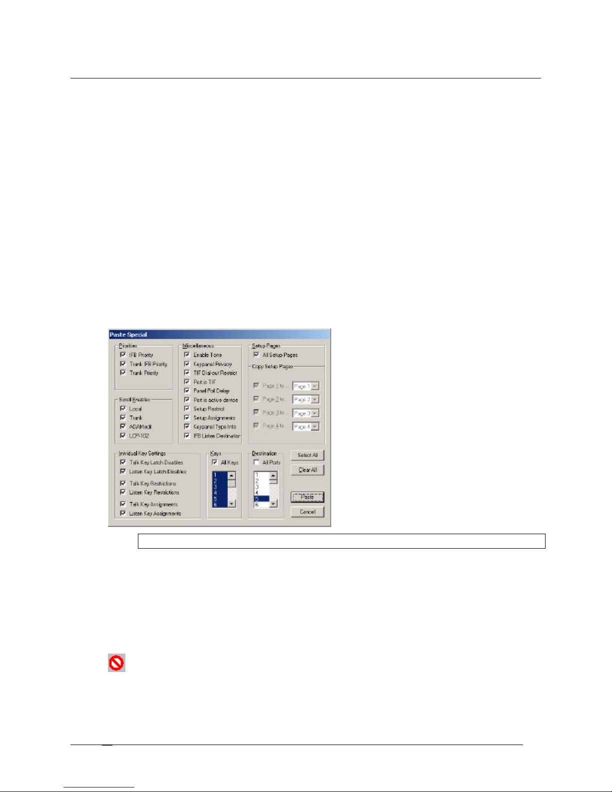
This opens the Paste Special screen, where you can select items you want to paste to the other intercom
ports.
Note: By default, all items in the Paste Special screen are checked.
8. Click Clear All.
All the check boxes are deselected
9. Under Miscellaneous, select Setup Restrict.
10. Under Destination, select All Ports.
11. Click Paste.
The Paste Special screen closes. On the Keypanels / Ports screen, the setup restrict icon has appeared for
all ports.
Telex Communications
26
Page 27
Key Restriction Setup using Copy and Paste Special
This procedure shows you how to quickly set all the restriction check boxes for all intercom ports. This prevents any
keypanel operator at any intercom port for changing the assignment on any key.
Note: You must be running in FILE mode. For more information on FILE mode, see
Connect/Disconnect to FILE mode.
1. On the Keypanels / Ports main screen, select the port with which you want to work.
2. Click Edit.
The Keypanel / Ports Configuration screen appears.
3. Verify that View by Setup Page is selected.
4. When verified, click OK.
The Keypanel / Ports Configuration screen closes.
5. From the Page drop down list, select any setup page (except the one assigned to Main keypanel). This
allows you to select the restrict check box for key 16.
6. In the combo box for Listen Key 1, press Ctrl + Shift + r.
The R check boxes for all listen keys are now selected.
7. In the combo box for Talk Key 1, press Ctrl + Shift + r.
The R check boxes for all talk keys are selected.
8. From the Edit menu, select Copy.
The entire setup page for the intercom is copied.
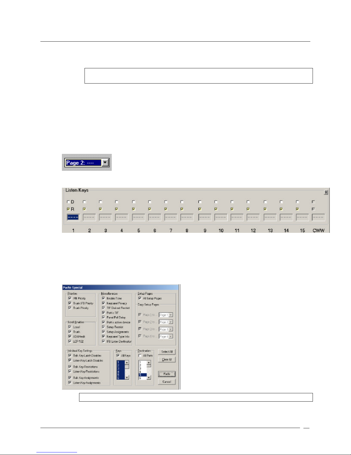
9. From the Edit menu, select Paste Special .
The Paste Special screen appears.
Note: By default, all items in the Paste Special screen are selected.
Telex Communications
27
Page 28
10. Click Clear All.
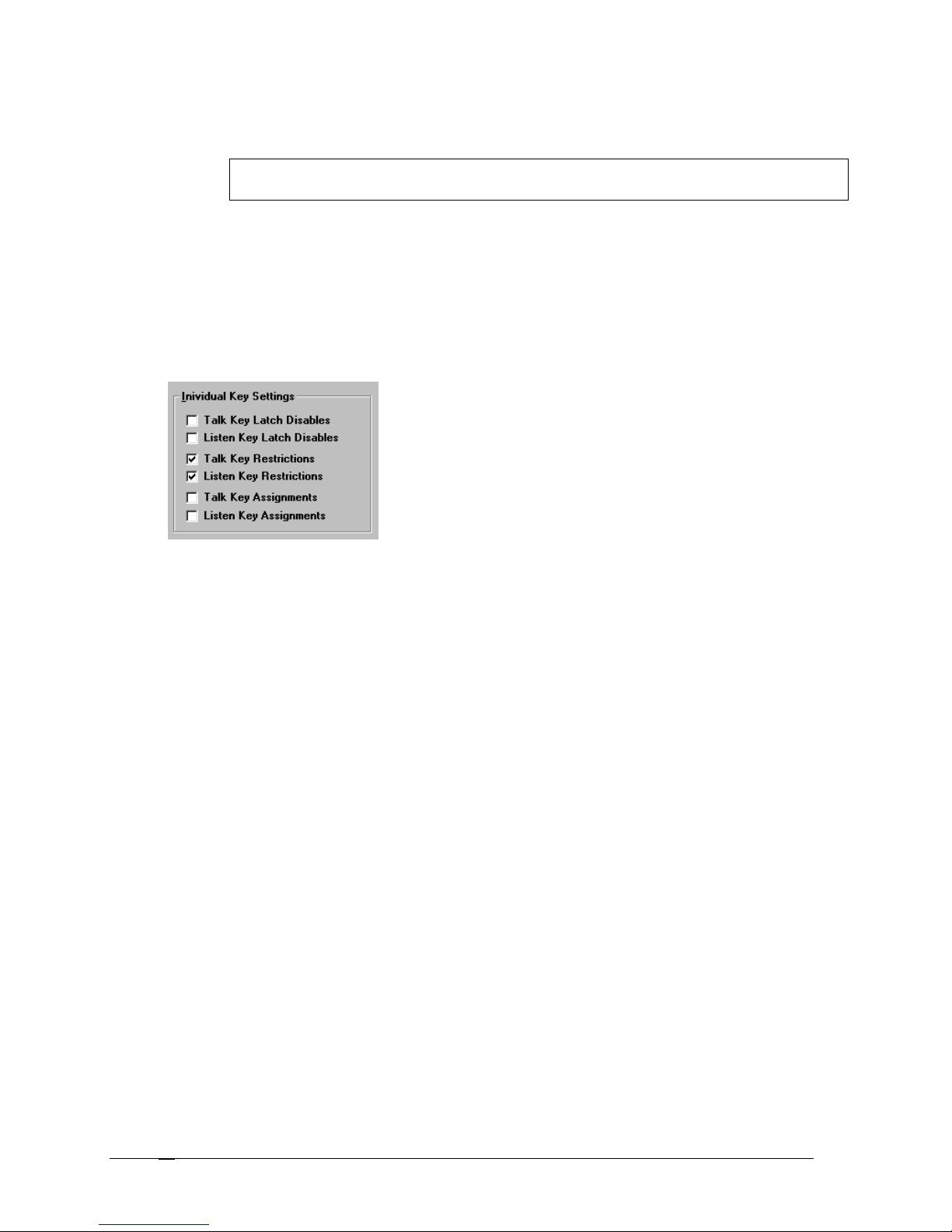
All items in the Paste Special screen are deselected.
Note: You must select All Setup Pages, and then deselect All Setup Pages to activate the
Individual Key Settings check boxes.
11. Select All Setup Pages.
All Setup Pages are selected, as well as Individual Key Settings and All Keys are selected.
12. Deselect All Setup Pages.
All Setup Pages are deselected, however, Individual Key Settings and All Keys stays selected.
13. Select All Ports.
All Ports are selected.
14. Under Individual Key Settings, deselect all check boxes, except the Talk Key Restrictions and Listen Key
Restrictions.
15. Under Copy Setup Pages, deselect all check boxes except for the page you are configuring (for example
Page 2 to…).
16. Click Paste.
It may take a few moments to copy the listen key settings for all intercom ports. Once complete, the Paste
Special screen closes.
17. Repeat steps 9 through 16 for all pages.
Once you are finished, you will see all the R boxes are selected on all the pages.
Hints:
• You can save a setup file where you have only configured the R settings. When you want to create a new setup
file, open the R setup file and use Save As to save the file under a new name. Add your other configuration
settings, such as talk key assignments, party lines, etc.
• To add R assignments to the ONLINE configuration, SAVE the ONLINE configuration to disk, and then open it
in FILE mode. Add the R assignments as described. Resave the file. Connect to the intercom system and use
Send File to update the intercom system.
Telex Communications
28
Page 29
Assigning Auto-Follow to all Listen Keys using Copy and Paste Special
This procedure shows you how to quickly set all listen keys to auto-follow for all intercom ports. You must be running
in FILE mode while configuring this setting.
1. On the Keypanel / Port screen, select the port with which you want to work.
2. Click Edit.
The Keypanels / Ports Configuration screen appears.
3. Verify that View by Setup Page is selected.
4. Click OK.
The Keypanels / Ports Configuration screen closes.
5. From the Page drop down list, select any setup page (except the one assigned to Main keypanel). This
allows you to select the restrict check box for key 16. For this exercise, Page 2 is selected.
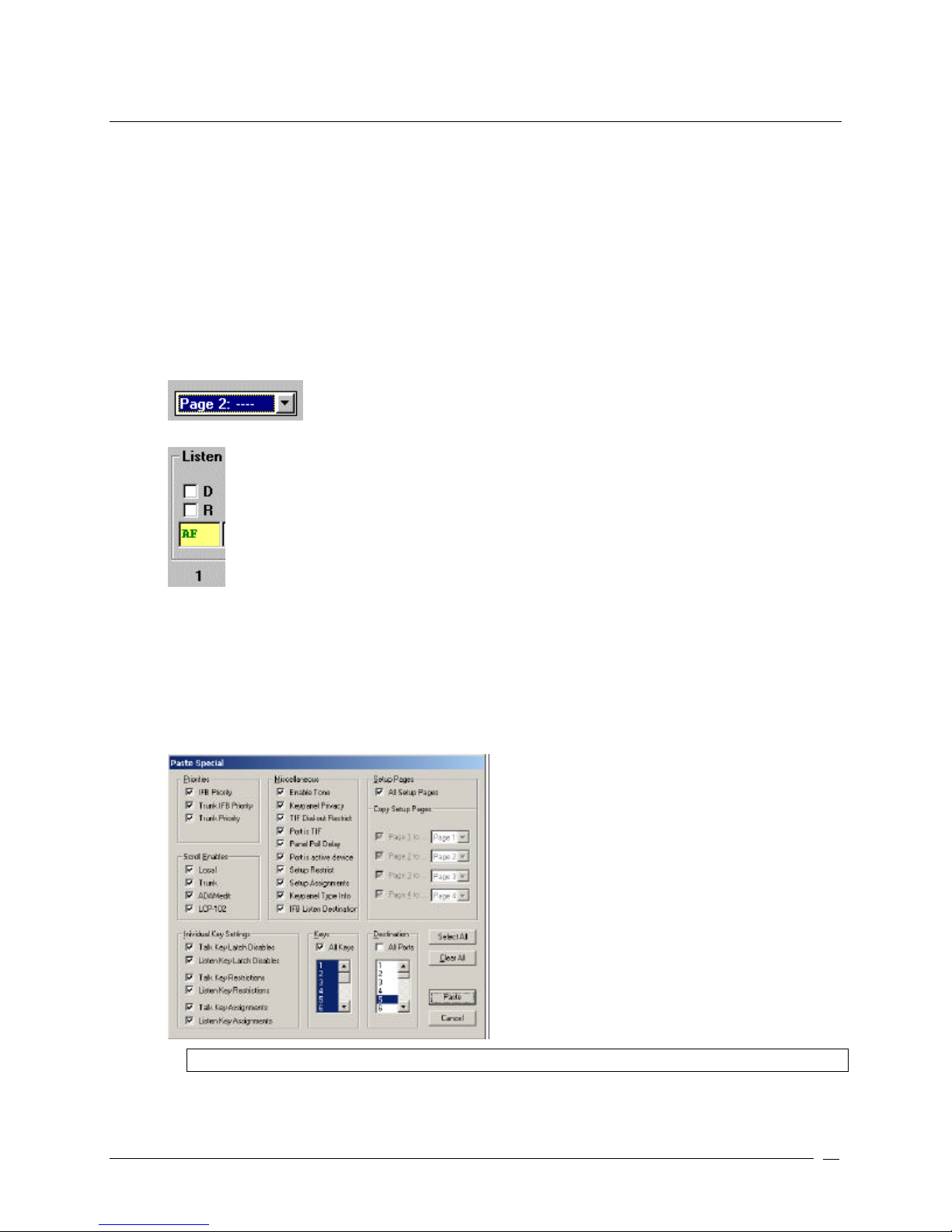
6. In the combo box for Listen Key 1, type AF (Auto-Follow).
7. Press Tab.
The cursor moves to Listen Key 2.
8. Repeat steps six and seven until all the listen keys are assigned AF (Auto-Follow).
9. From the Edit menu, select Copy.
The entire setup page for the intercom is copied.
10. From the Edit menu, select Paste Special.
The Paste Special screen appears.
Note: By default, all items in the Paste Special screen are selected.
11. Click Clear All.
All items in the Paste Special screen are deselected.
Telex Communications
29
Page 30
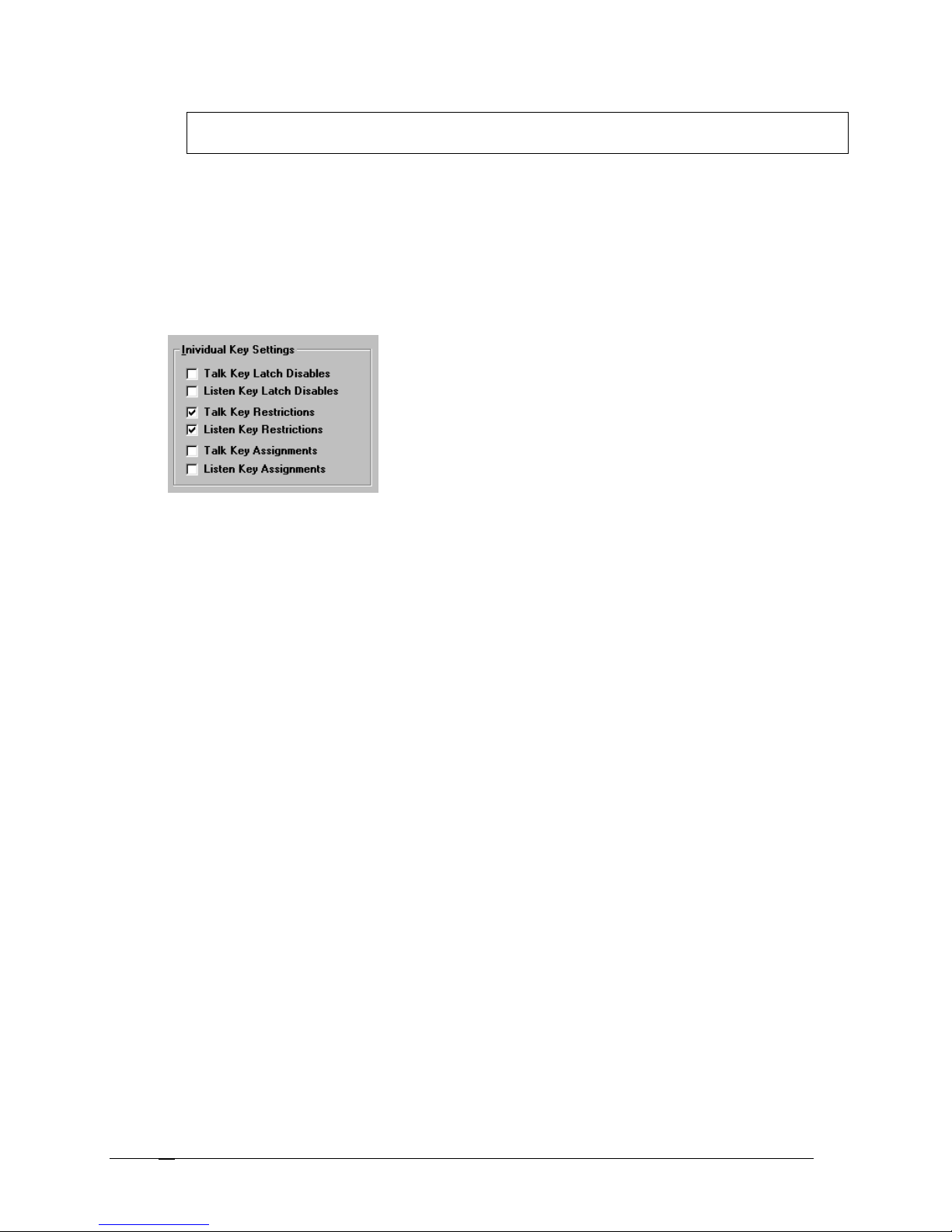
Note: You must select All Setup Pages, and then deselect All Setup Pages to activate the Individual
Key Settings check boxes.
12. Select All Setup Pages.
All Setup Pages are selected, as well as Individual Key Settings and All Keys are selected.
13. Deselect All Setup Pages.
All Setup Pages are deselected, however, Individual Key Settings and All Keys stays selected.
14. Select All Ports.
All Ports are selected.
15. Under Individual Key Settings, deselect all check boxes, except the Talk Key Restrictions and Listen Key
Restrictions.
16. Under Copy Setup Pages, deselect all check boxes except for the page you are configuring (for example
Page 2 to…).
17. Click Paste.
It may take a few moments to copy the listen key settings for all intercom ports. Once complete, the Paste
Special screen closes.
18. Repeat steps 9 through 16 for all pages.
Once you are finished, AF is assigned on all setup pages at all intercom ports.
Hints:
• You can save a setup file where you have only configured the AF settings. When you want to create a new
setup file, open the AF setup file and use Save As to save the file under a new name. Add your other
configuration settings, such as talk key assignments, party lines, etc.
• To add AF assignments to the ONLINE configuration, SAVE the ONLINE configuration to disk, and then open it
in FILE mode. Add the AF assignments as described. Resave the file. Connect to the intercom system and use
Send File to update the intercom system.
Telex Communications
30
Page 31
M
Assigning Keys
Warning: Before attempting any kind of key assignment make sure the "Upload Alphas" message is not displayed in
the lower-left corner of the screen. When starting AZedit, the names for key assignments and intercom systems will
not display properly until all alphas are uploaded. In a very large intercom system, this could take several minutes.
1. From the Keypanels / Ports screen, right-click in a Talk or Listen combo box.
A pop up menu appears.
2. Select Change Assignment.
The Select Key Assignment screen appears.
Note: "Phones" will only appear in the list if a TIF-951 is connected and operating. In this case,
you can select Phones" rather than "Ports" to assign a phone key.
3. In the System drop down list, select the intercom system where the destination is located that you want to
assign.
4. In the key type list, select the type of intercom key you want to assign.
5. In the name list (on the right), select a name (alpha) for the key.
6. Click OK.
The Selected Key Assignment screen closes and the selected name appears in the key assignment combo
box on the Keypanels / Ports screen.
Note: When you select Special Functions, you can use the no assignment name (----) as a way
to erase a previous assignment.
Notes:
• For the setup page that is assigned to the main keypanel, you cannot assign or use key 16, as this is used for
incoming messages (this is also referred to as the call waiting window, CWW). For all other setup pages, you
may assign and use key 16.
• If you are working with keypanels and expansion panels that have 16 keys, it is highly recommended you set
the Default View (found on the Keypanel/Port Setup page) to by Panel Type. However, if you are using the by
Setup Page view, you can switch to the by Panel Type view by pressing Ctrl+Tab on the keyboard.
Telex Communications
31
Page 32

• You can assign a key by position the cursor in the key assignment text box and then entering the name. Be
aware, if there are duplicate alphas in the system, the key may take on the wrong assignment.
• After a talk key is assigned, you will notice a new key assignment text box activates under the talk key (except
the KP-32 in View by Panel Type mode). This can be used as a second key assignment that will activate along
with the first key assignment. This is referred to as a level 2 talk key.
If more than two talk levels are defined in the intercom configuration (or if you are working with KP-32 in View by
Panel Type mode) you will also see a scroll arrow at the right side of the screen. Use this scroll arrow to select
which talk levels you want to view.
Telex Communications
32
Page 33
Keypanel/Ports Configuration
The Keypanel/Ports configuration screen is used to configure a keypanel in the intercom system. From this screen,
you can setup your keypanels, choose different screen View options, restrict users from setup, set specific priorities,
set delay times, IFB listen destinations, enable tone, keypanel privacy, TIF dial out restrictions, and assign a port as a
TIF.
The Setup page of the Keypanel/Port Configuration screen is for higher-level configuration options, while the
Advanced Tab allows you to assign more specific options and restrictions to a keypanel.
To open the Keypanel/Port Configuration screen, do the following:
1 From the Keypanel setup screen, click Edit….
The Keypanel/Port Configuration screen appears.
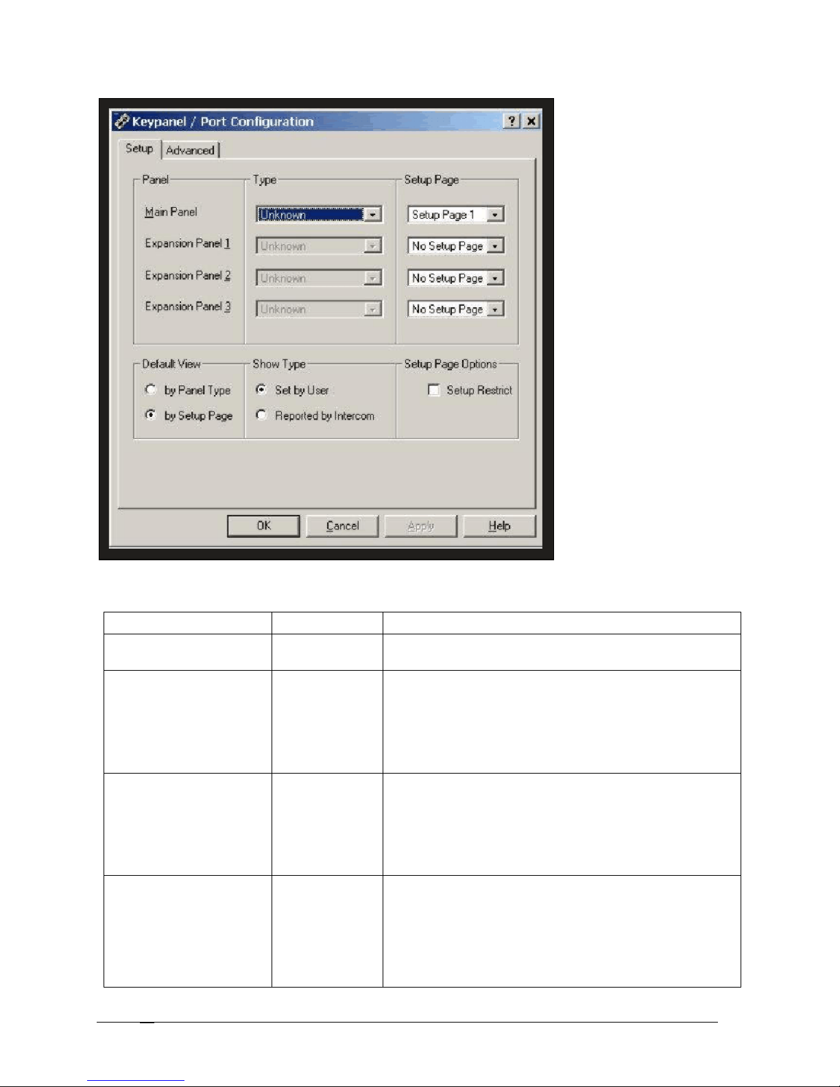
Setup
Use the Setup tab to configure an intercom port for use with a keypanel. Each keypanel can have up to four setup
pages of key assignments, and each setup page can assign up to 16 pairs of talk and listen keys. Typically, one
setup page is used for the main keypanel, and one setup page is used for each expansion panel connected to the
main keypanel.
Note: Some keypanels may have more or less than 16 keys. There may be cases where all 16
keys on a setup page are not used. There may also be cases, such as with the KP-32 keypanel,
where the keypanel itself uses all of the keys on more than one setup page.
Telex Communications
33
Page 34
KP-12 will display only 12 Talk and Listen keys. Typically, view
Screen Items
Screen Item Field Type Description
Panel display
Type drop-down list
Setup Page drop-down list
Default View radio button
The Panel field displays which panel is being configured (i.e.,
Main Panel, Expansion Panel 1, etc.).
The Type field gives users a list of keypanels that can be
assigned to the main panel. For example, KP-32, TIF 2000,
etc.
From the Type drop down list, select the type of keypanel
being assigned.
The Setup Page drop down list gives users a list of pages
available for configuration on the keypanel. For more
information, see Pages in the glossary
From the Setup Page drop down list, select the page to be
configured (i.e., page 1, page 2, etc.).
Default View gives the user the option of how to view
keypanels in the application.
by Panel Type: The Keypanel / Ports screen will only display
the correct quantity of Talk and Listen keys based on the Type
settings. For example, a setup page that is assigned to the
Telex Communications
34
Page 35

Screen Item Field Type Description
by Panel Type is the preferred mode because the user cannot
assign more keys than are actually available on the keypanel.
by Setup Page: The Keypanel / Ports screen displays
all 16 Talk and Listen key assignments available on a setup
page, regardless of whether the keypanel or expansion panel
has that number of keys.
Note: When viewing the setup pages for a particular
intercom port, you can switch back and forth between
view by Panel Type and view by Setup Page by pressing
Ctrl+Tab on the computer keyboard. If you want to
change the view mode for all intercom ports, use
Shift+Ctrl+Tab.
In the Default View field, select either the by Panel Type or by
Setup Page radio button.
Show Type radio button
The Show Type gives the user the option to manually choose
the type of keypanel being configured or to let the intercom
automatically set the type of keypanel.
Note: You must be working in ONLINE mode to select
Reported by Intercom.
In the Show Type field, select either Set by User or Reported
by Intercom.
Setup Page Options check box
The Setup Page Options field gives the user the option to
restrict other users to change the setup configuration from a
keypanel.
By default, keypanel operators can change the setup page
usage from their keypanels.
Note: You may want to select the Setup Restrict check
box for all intercom ports.
From the Setup Page Options field, select the Setup Restrict
check box if you want to restrict users from changing setup
options on the keypanel.
OK button Accepts the changes made and closes the Keypanel/Port
Configuration screen.
Click OK.
The Keypanel/Port Configuration screen closes and changes
are saved.
Cancel button Clears the changes made and closes the Keypanel/Port
Configuration screen.
Click Cancel.
The Keypanel/Port Configuration screen closes and changes
are not saved.
Apply button Applies the changes made to the keypanel/port configuration
screen and leaves the window open.
Click Apply.
The changes made to the Keypanel/Port Configuration screen
are applied and the screen stays open.
Telex Communications
35
Page 36

Right-Click Guide to the Keypanel/Port Configuration Setup screen
There are no right-click menus for this screen.
Telex Communications
36
Page 37
Keypanel / Ports Configuration
Advanced
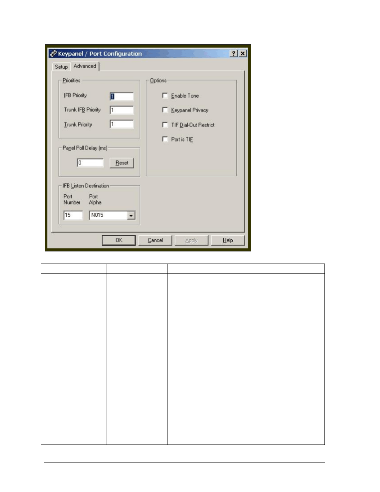
Use the Advanced tab to further configure an intercom port for use with a keypanel. Set priorities for keypanels in
IFB, Trunk IFB, and Trunk situations. Set the Panel Poll Delay (the amount of time the keypanel waits for data
transmission). Panel Poll Delays are used when remote keypanels are in the system configuration. On this screen,
set the IFB Listen Destination port and set Options, such as Enable Tone, Keypanel Privacy, Dial-Out restrictions,
and Port is TIF parameters.
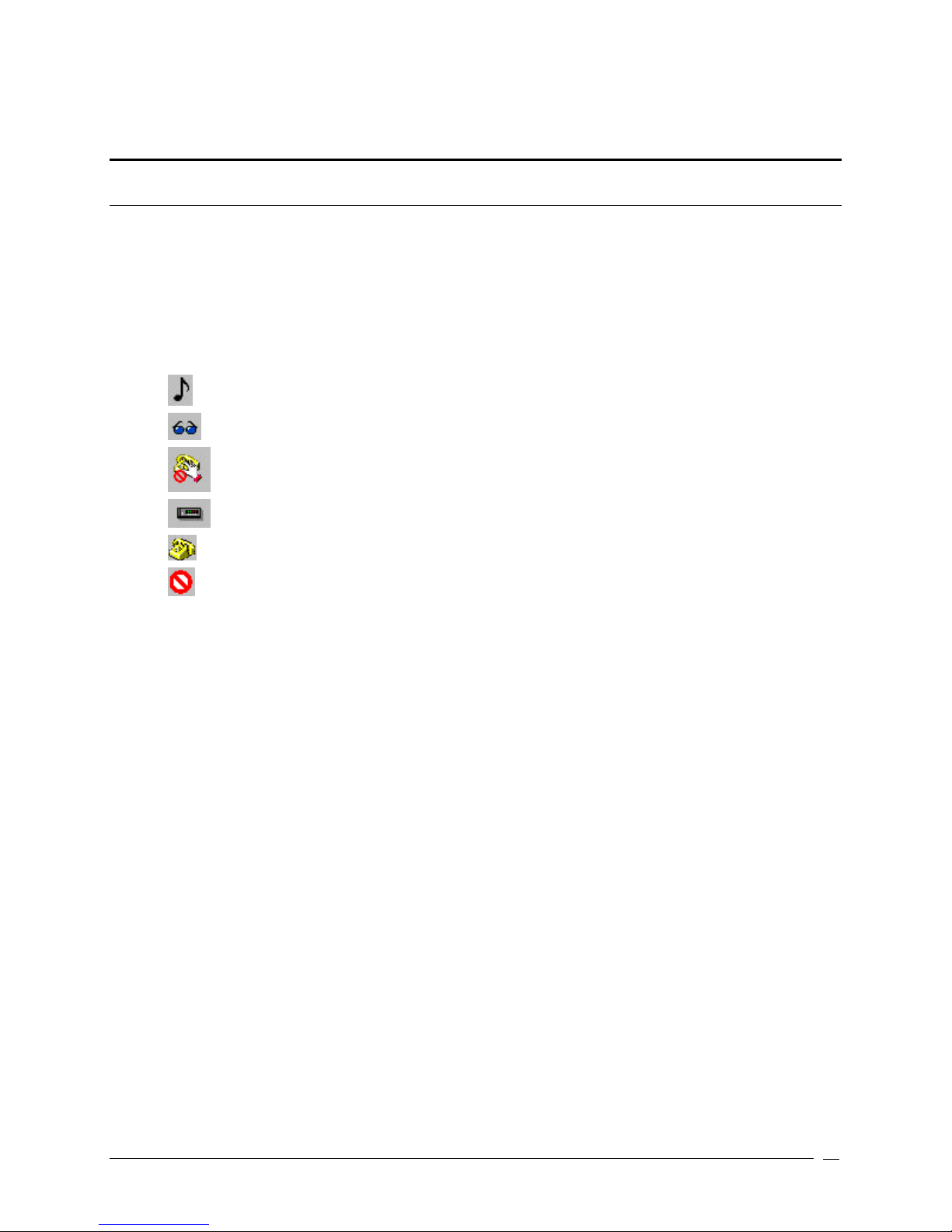
The following icons are displayed in the Keypanel / Port Settings group (they appear beneath the Edit button)
These icons are to remind you certain selections have been made using the Edit button.
Musical Note Icon: Indicates that Enable Tone is checked.
Sunglass Icon: Indicates that Keypanel Privacy is checked.
No Phone Dial Icon: Indicates that TIF Dial-Out Restrict is checked.
Modem Icon: Indicates that a Panel Poll Delay has been specified.
Phone Icon: Indicates that Port is TIF is checked.
"No" Symbol: Indicates that Setup Restrict is checked.
To open the Advanced Keypanel / Ports Configuration screen do the following:
1. Click Edit
The Edit Keypanel / Ports Configuration screen appears.
2. Click the Advanced Tab.
The Advanced screen appears.
Telex Communications
37
Page 38
Screen Items
Screen Item Field Type Description
Priorities text field
The Priorities field gives the user a numerical option to
select which keypanel receives first access to an IFB, trunk
IFB or Trunk in cases where two or more keypanels are
trying to access the same port at the same time.
IFB Priorities Description
IFB priorities determine which keypanel gets first access to an
IFB in cases where two or more keypanels are trying to access
the same IFB at the same time. By default, the IFB priority for
each intercom port can be individually set to any number from 0
through 3. With 3 being the highest priority.
With the priority set to 3, the keypanel overrides any other
keypanel set at a lower priority. Keypanels that are set to the
same priority can simultaneously access IFB's.
To add more IFB priority levels in the intercom configuration
settings, see Adding more IFB Priority Levels.
Trunk IFB Description
Trunk IFB priority determines which keypanel gets first access to
a remote IFB in cases where two or more keypanels are trying
to access it at the same time.
For each keypanel, the trunk IFB priority can be set to any
number from 1 through 3. With priority 3 being the highest
priority. With the priority set to 3, the keypanel overrides any
other keypanel set to a lower priority. Keypanels that are set to
the same priority can simultaneously access IFB's.
To add more Trunk IFB priority levels in the intercom
configuration settings, see Adding more IFB Priority Levels.
Telex Communications
38
Page 39
Screen Item Field Type Description
listening to another keypanel by means of a point
-to-
point listen key.
Trunk Priority Description
Depending on how many trunking ports are setup, there may be
occasions when there are not enough available for everyone to
use. In such cases, trunk priority settings control the order in
which keypanels gain access to trunked ports.
Each keypanel can be assigned a trunk priority ranging from 1
through 10. With 10 being the highest priority. With a trunk
priority setting of 10, a keypanel will take over a trunking port
from a keypanel with a lower setting when there are no other
trunking ports available.
Note: Before changing intercom
configuration settings, we recommend you
read the intercom configuration description.
1. In the Priorities field, enter a priority for IFB, Trunk
IFB, or Trunk.
Panel Poll Delay text field
Panel Poll Delay is used when a keypanel's data line is
connected to the intercom port via a modem link from a
remote location. In this situation, there may be a slight delay
in data transmission from the remote keypanel to the
intercom system. This can cause sporadic operation or no
operation at all.
The panel poll delay first must be activated through the
Options > Preferences menu. For more information on
Activating the Panel Poll Delay option, see Panel Poll Delay
Activation.
1. In the Panel Poll Delay field, enter the delay time
the intercom system will wait for data
transmissions.
Reset button
The Reset button clears the Panel Poll Delay field and sets
the delay at zero. Zero is the default setting.
1. Click Reset.
The Panel Poll Delay resets to zero.
IFB Listen Destination text field and drop
down list
IFB Listen Destination is a keypanel setting used with the
IFB Listen Source feature. It redirects the IFB listen audio
from the keypanel speaker or headset to an external device,
such as a studio monitor, when the keypanel operator
activates a key to listen to the talent.
For information on IFB Setup Procedures, see IFB Setup
Procedures.
1. In the Port field, enter the port to which you want to
redirect the audio.
Once the Port number is entered, the Port Alpha
field will automatically fill with the Alpha for that
port.
Options check box There are four options that can be configured from the
Options field:
Enable Tone:
Digital matrix keypanels are equipped with internal tone generators
for signal tracing and troubleshooting. The tone signal feeds directly
into the matrix so it can be used as a voice substitute for testing
purposes.
Keypanel Privacy
The keypanel privacy feature prevents other keypanels from
Telex Communications
39
Page 40

Screen Item Field Type Description
However, if the private keypanel talks to another keypanel, it will be
heard. The keypanel privacy feature requires ADAM Master
Controller Firmware Version V9.5.0 or greater.
Note: Keypanel privacy does not prevent someone from listening to
a private panel via other means. For example, if the private
keypanel is a member of a party line or special list, it can be heard
by anyone listening to the party line or special list.
TIF Dial Out Restrict
TIF Dial-Out Restrict prevents a keypanel operator at an intercom
port from dialing out via a TIF-2000 Telephone Interface. The
keypanel operator is able to receive incoming phone calls but
cannot dial out or send a hang-up signal from the keypanel.
In most cases, the TIF-2000 will detect that the caller at the far end
has hung up and it will also hang up. However, some telephone
systems do not provide any hang up indication. In this case, if an
incoming call is answered from a keypanel that has TIF dial-out
restrict activated, the phone line will remain engaged after the caller
at the other end hangs up.
Port is TIF
Port is TIF appears only when TIF-2000 support is set up. This
check box enables the enhanced dialing features of the KP-32
keypanels.
1. In the Options field, select one or more of the options
check boxes.
OK button Accepts the changes made and closes the Keypanel/Port
Configuration screen.
1. Click OK if you want to accept the changes,
otherwise click Cancel.
The Keypanel/Port Configuration screen closes
and changes are saved.
Cancel button Clears the changes made and closes the Keypanel/Port
Configuration screen.
1. Click Cancel.
The Keypanel/Port Configuration screen closes
and changes are not saved.
Apply button Applies the changes made to the keypanel/port configuration
screen and leaves the window open.
1. Click Apply.
The changes made to the Keypanel/Port
Configuration screen are applied and the screen
stays open.
Right-Click Guide to the Keypanel/Port Configuration Advanced screen
Built into AZedit are many different ways to get to the same information, by buttons, menus, and right-clicking. The
following is a list of menus and screens you can access by right clicking from the Advanced main screen.
Telex Communications
40
Page 41

Right Click Action Right-Click Result
Right-click in any of the following fields:
IFB Priority
Trunk IFB Priority
Trunk Priority
Panel Poll Delay
Port Number
A popup menu appears that gives you the option to:
Undo – reverses the last action--for example, to undo
a deletion, thus restoring deleted text to a
document.
Cut - removes part of a document, usually placing it
temporarily in memory so that the cut portion can
be inserted (pasted) elsewhere.
Copy - duplicates information and reproduce it in
another part of a document, in a different file or
memory location, or in a different medium
Paste - inserts text or a graphic that has been cut or
copied from one document into a different location
in the same or a different document.
Delete - eliminates text, a file, or part of a document
with the intention of removing the information
permanently.
Telex Communications
41
Page 42

Panel Poll Delay Activation
Panel Poll Delay is typically used when a keypanel's data line is connected to the intercom port via a modem link
from a remote location. By setting a delay time, the intercom system waits longer for data transmissions from the
remote keypanel. The delay time can be set anywhere from 0 milliseconds (1/1000 of a second) to 500 milliseconds
(500/1000's of a second, or 1/2 second).
Important: Connect only one remote keypanel per Audio I/O card, and assign only one panel poll delay per Audio I/O
card. Also, since excessive poll delay can impair system performance, use the minimum delay required to assure
proper operation of the remote keypanel. However, allow for the possibility of fluctuations in the delay time.
To activate the panel poll delay, do the following:
1. From the Options menu, select Preferences.
The Application Preferences screen appears.
2. Select the Advanced tab.
The Advanced screen appears.
3. Select the Enable panel poll delay support check box.
4. Click Apply.
5. Click OK.
Panel Poll Delay is activated and may be adjusted in the Keypanel / Ports Configuration Advanced screen.
Telex Communications
42
Page 43
Gain Setup for Output Port
Gain is simply the increase of a signal accomplished by increasing the size of the amplitude. AZedit uses Unity Gain.
Unity Gain is when the amplitude that the audio comes into the matrix system is sent out at the same amplitude. For
example, if +10 dB comes into the matrix that is set with 0 gain, then +10 dB will leave the matrix. However, if +10 dB
comes into the matrix that is set with –4 dB gain, then +6dB will leave the matrix. The unity point is seen as zero dB,
by default. The minimum adjustment for gain levels in AZedit is +/-.5 dB. A negative gain is known as attenuation
There are three gain adjustments that can be manipulated from this screen:
Point-to-Point - Use point-to-point listen gain to adjust the level at which the currently selected intercom port hears a
selected other intercom port. Point-to-point listen gain is the same thing as Crosspoint Gain, and the adjustment can
be made on this screen or the Crosspoint Gain screen.
Note: When you adjust the level at which one port hears another port, keep in mind this affects all
communications between the two ports. Use the following examples using various types of
communication where port 1 is talking to port 2 follow to learn what can happen when you adjust
the gain levels:
Example 1, Point to Point: Port 1 could press a point-to-point talk key to talk to port 2. Port 2 will
hear port 1 at whatever level has been set in the Point-to-Point Listen dialog.
Example 2, Special List: Port 2 could be a member of a special list. Let's say the special list is
named CREW. Port 1 could have a key assigned to talk to special list CREW. In this case, port 2
will also hear port 1 at the level that is set in the Point-to-Point Listen dialog for port 2. Even though
port 1 is not using a point-to-point key, there is still a point-to-point relationship between port 1 and
every member of special list CREW.
Example 3, IFB: Port 2 could be specified as the output port for an IFB. Let's say the IFB is named
TAL1. Port 1 could have a key assigned to talk to IFB TAL1. In this case, port 2 will hear port 1 at
the level that is set in the Point-to-Point Listen dialog for port 2. Even though port 1 is not using a
point-to-point key, there is still a point-to-point relationship between port 1 and the output specified
by the TAL1 IFB, which is port 2. Now, let's say that port 3 also has TAL1 assigned to a key. If the
point-to-point listen setting for port 2 listening to port 3 is different than the setting for port 2
listening to port 1, the levels will sound different when port 1 or port 3 talk to port 2 using the TAL1
key.
Party Line - Use Party Line Listen Gains to adjust the level at which a specific intercom port hears a specific party
line.
Note: You can also set the party line listen gains using party line gain setup.
Analog I/O - The Analog I/O Gain setting indicates the amount by which the input level to this intercom port has been
increased or decreased from the normal 0 dB level. The Output Gain setting indicates the amount by which the output
level from this intercom port has been increased or decreased from the normal 0 dB level.
Note: You can view the current input and output gain settings for this intercom port, but you cannot
make changes in this dialog box. To make changes to these settings, close the Gain Setup dialog
box. Then, in the System menu, point to Gains, and select Analog Input/Output Gains from the pop
up menu. This will open the Analog Input / Output Gains view.
To Open the Gain Setup Output Port screen, do the following:
1. From the Keypanel/Port Main screen, click the Gain button .
The Gain Setup For Output Port screen appears.
NOTE: You can also access the Gain Setup For Output Port screen by right clicking a talk or listen
key on the Keypanel/Port main screen.
Telex Communications
43
Page 44
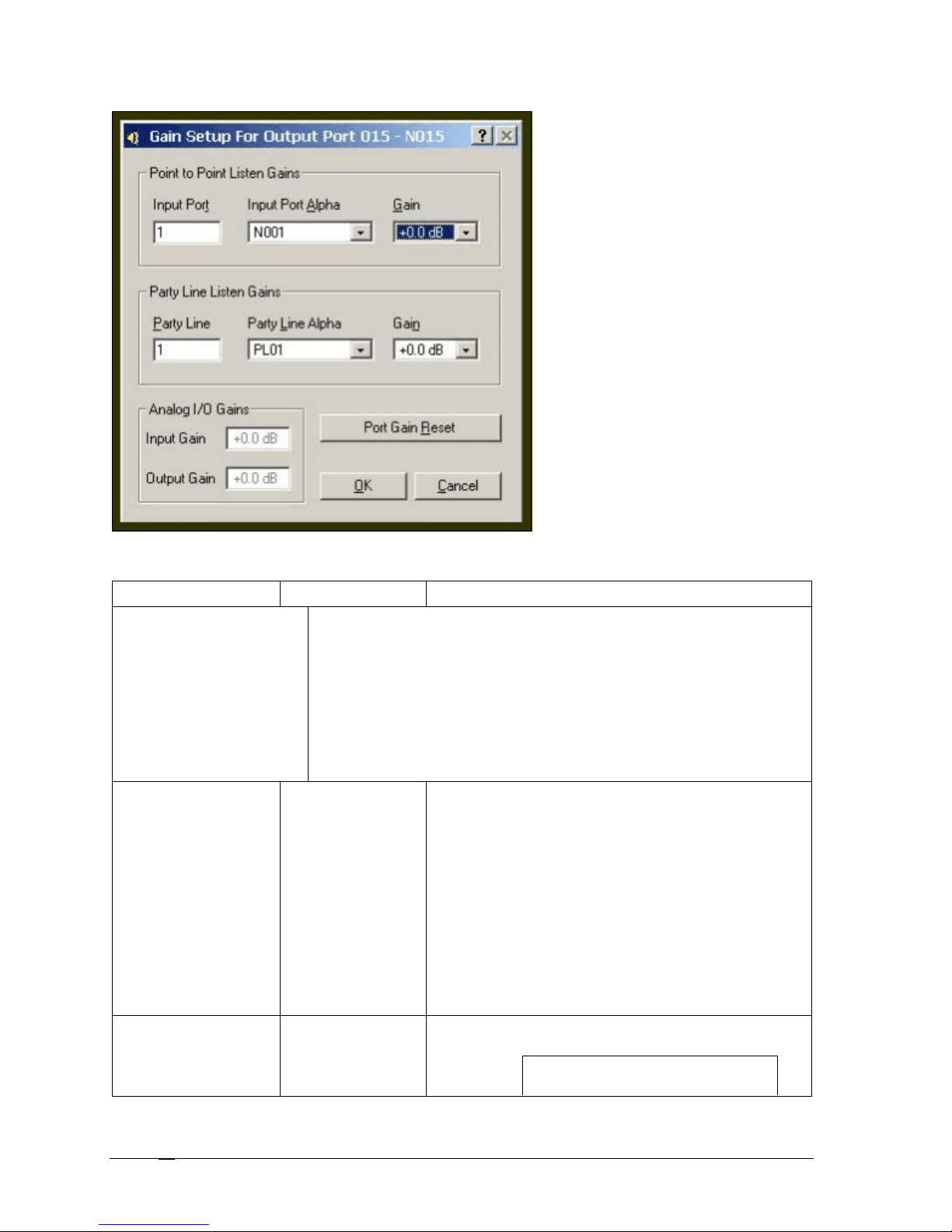
first, the Input Port will automatically
Screen Items
Screen Item Field Type Description
Point to Point Listen Gains RTS Keypanels are calibrated to send and receive audio at standard operating
levels of the intercom system. Normally, no audio gain adjustment is required
when connecting these ports. However, many other types of devices may not
operate at the standard intercom system levels.
To insure signal level compatibility between the various types of devices and
the intercom systems inputs and outputs, there are separate analog input and
output gain adjustments for each intercom port. In addition to the analog input
and output gain adjustments for each port, it is also possible to adjust the
listen gain for any specific port when listening to any other specific port. This is
called the point-to-point listen gain adjustment.
Input Port text field
The Input Port number of the keypanel to which the user is
adjusting the listen gain level.
Note: You can also select the Input Port Alpha first, from
the Input Port Alpha drop down box. If the Port Alpha is
selected first, the Input Port will automatically fill with the
appropriate port number.
1. In the Input Port field, enter the port number of
the port for which you want to change the listen
gain level.
Once the Input Port field is filled, the Input Port
Alpha will automatically fill with the correct Port
Alpha.
Input Port Alpha drop down list
The Input Port Alpha is the recognizable name the user
renamed the port.
Note: If the Port Alpha is selected
Telex Communications
44
Page 45
Screen Item Field Type Description
fill with the appropriate port number.
1. From the Input Port Alpha drop down list, select
the Port Alpha for which you want to change the
gain level.
Gain drop down list
Gain is the level at which the port listed at the top of the
screen will hear the input port that you select. Gain
adjustments can range from +6dB to –99 dB.
1. From the Gain drop down list, select the new gain
level.
Note: Gain adjustments take effect
when you send your changes to the
intercom system. Gain settings are
saved in your setup file if you save it
to disk.
Party Line Listen Gains
Party Line text field
The Input Port number of the keypanel to which the user is
adjusting the gain level.
Note: You can also select the Input
Party Line Alpha first. If the Party Line
Alpha is selected first, the Party Line
will automatically fill with the
appropriate port number.
1. In the Input Port field, enter the port number of
the port for which you want to change the gain
level.
Party Line Alpha drop down list
The Party Line Alpha is the recognizable name the user
renamed the party line.
Note: You can also enter the Party
Line first. If the Party Line is
selected first, the Party Line Alpha
will automatically fill with the
appropriate port number.
1. From the Party Line Alpha drop down list, select
the Party Line Alpha for which you want to
change the gain level.
Gain drop down list
Gain is the level at which the port listed at the top of the
screen will hear the party line that you select. Gain
adjustments can range from +6dB to –99 dB.
1. From the Gain drop down list, select the new gain
level.
Note: Gain adjustments take effect
when you send your changes to the
intercom system. Gain settings are
saved in your setup file if you save
it to disk.
Input Gain text field
Telex Communications
Analog I/O Gains
The Input Gain is the amount of gain the input level to the
intercom port has been increased or decreased. Gain
adjustments can range from +20dB to –20dB.
45
Page 46
Screen Item Field Type Description
Output Gain text field
The Output Gain setting is the amount of gain the output
level to the intercom port has been increased or decreased.
Gain adjustments can range from +20dB to –20dB.
Port Gain Reset button
The Port Gain Reset button restores the current gain
setting to its default db.
Note: Gain resets take effect when
you send your changes to the
intercom system. Gain settings can
also be saved in your setup file, if
you save it to disk
1. Click Port Gain Reset, if you want to reset
the changes you made.
OK button Saves the changes made and closes the Gain Setup
screen.
1. Click OK.
The gain setup changes are saved and the
screen closes.
Cancel button Clears the changes made and closes the Gain Setup
screen. The changes are NOT saved.
1. Click Cancel.
The gain setup screen closes and the
changes are not saved.
Right-Click Guide to the Gain Setup to the Output Port screen
Built into AZedit are many different ways to get to the same information, by buttons, menus, and right-clicking. The
following is a list of menus and screens you can access by right clicking from the Gain Setup to the Output port
screen.
Right Click Action Right-Click Result
Right-click in any of the following fields:
• Point to Point Listen Gains
• Party Line Listen Gains
• Analog I/O Gains
A popup menu appears that gives you the option to:
Undo – reverses the last action--for example, to undo
a deletion, thus restoring deleted text to a
document.
Cut - removes part of a document, usually placing it
temporarily in memory so that the cut portion can
be inserted (pasted) elsewhere.
Copy - duplicates information and reproduce it in
another part of a document, in a different file or
memory location, or in a different medium
Paste - inserts text or a graphic that has been cut or
copied from one document into a different location
in the same or a different document.
Delete - eliminates text, a file, or part of a document
with the intention of removing the information
permanently.
Telex Communications
46
Page 47
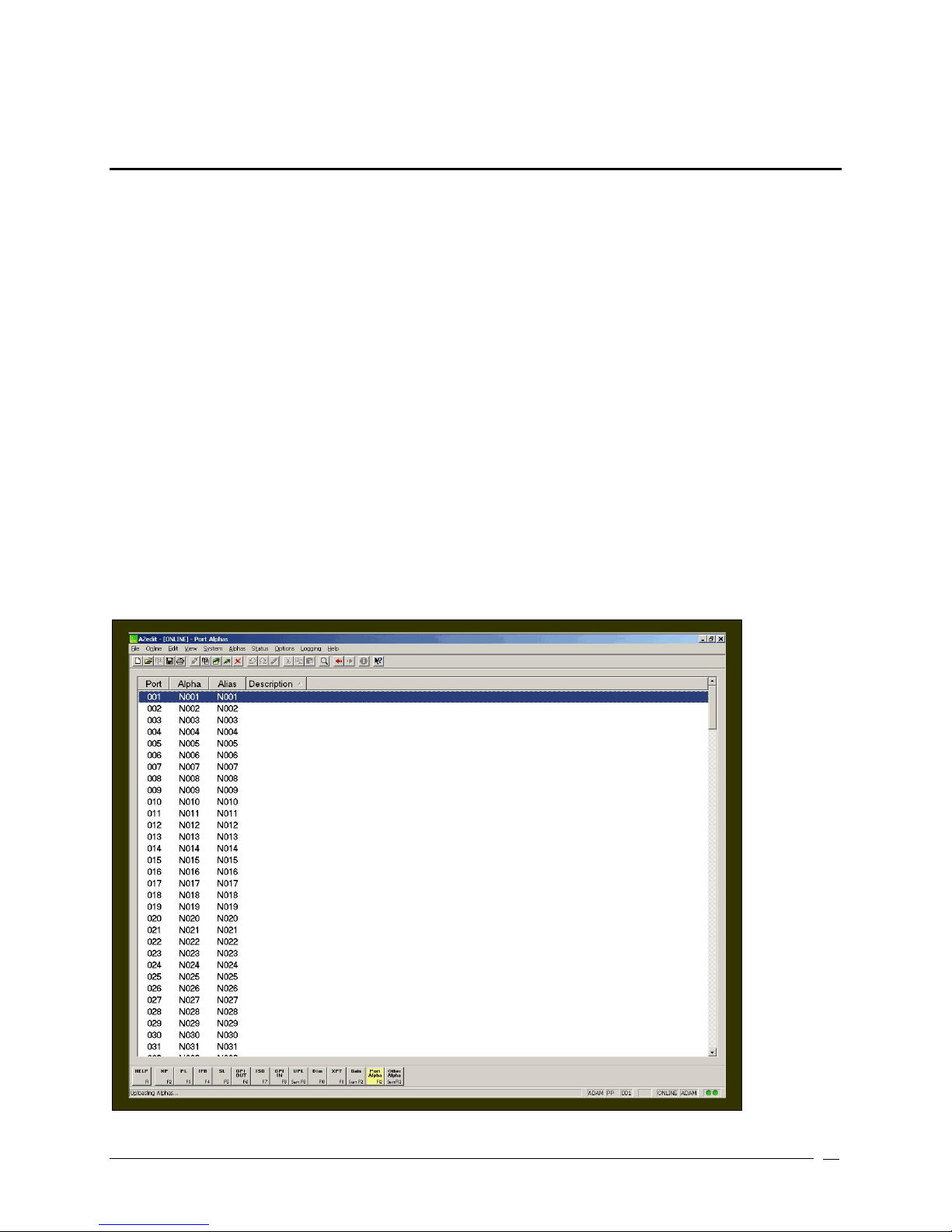
Port Alpha
Ports are the individual channels that devices are connected to within the intercom system.
Devices can include:
• 2-way communication devices, such as keypanels, belt packs etc.
• Audio sources, such as broadcast feeds or background music
• Miscellaneous audio output devices, such as powered loudspeakers, PA systems etc.
Communication between Ports
The audio signal from any input port can be routed to any output port. For example, during keypanel setup, you
assign keypanel keys so that keypanel operators can talk and listen to other intercom ports. Communication of this
type is called point-to-point communication. You can also route signals between intercom ports without keypanels.
One way to do this is to force crosspoints in the Crosspoint Status screen. For more information on Crosspoint Status,
see Crosspoint Status. Another way to do it is with a GPI input.
Port ID Numbers and Alphas
Intercom ports have identification numbers 001, 002 etc. These numbers cannot be changed.
Each intercom port also has a default name, called an "alpha". This name appears in the alphanumeric displays on
keypanels when you assign the ports to keys for talking and listening. The default alpha names are N001, N002 etc.
These default alpha names can be changed to ones that are meaningful to keypanel operators using Port Alpha
setup.
Telex Communications
47
Page 48
Screen Items
Screen Item Field Type Description
Port column display
The Port column displays the port identification number for
the intercom port. This identification number cannot be
changed.
Alpha column display
The Alpha column displays the label given to the port
(input/output) of the matrix. Alphas are the names that
appear in the alphanumeric displays on keypanels when
keys are assigned to talk to destinations in the intercom
system. Alpha names for intercom ports are assigned using
Port Alphas setup. Alpha names for everything else are
assigned using Other Alphas setup.
Note, 4 characters are shown here but alphas may be
constructed using 4 ,6 or 8 character labels which may be
used by keypanels with appropriate sized key displays
To change the Alpha, do the following:
1. From the Alpha screen, double-click the port for which
you want to change the Alpha.
The Edit/Alpha Description screen appears.
2. In the Description field, enter a description of the port
(up to 25 characters).
3. In the Alpha field, enter a meaningful name for the
port. For example, if Port 1 is the radio station, you
may call it by the radio call letters.
4. Click Done, if you are finished renaming the Ports,
otherwise, click Next to prompt the next port.
Alias column display
The Alias column displays the Alias assigned to a port.
Aliases are used only with trunked intercom systems. Alias
names are used to identify destinations in your intercom
system to AZedit administrators and keypanel operators in
remote intercom systems. Aliases are provided because
sometimes an Alpha name that is being used in your local
intercom system is also being used in another remote
intercom system. In this case, you can enter an Alias name
that will not conflict with the name that is already in use. This
column will not display unless trunking is enabled. For more
information on trunking, see the TM2000 user manual.
Description column display
The Description column displays a description of what the
port is used for (i.e., listening to a radio station, talking to a
specific user, etc…)
Right-Click Guide to the Alpha screen
Built into AZedit are many different ways to get to the same information, by buttons, menus, and right-clicking. The
following is a list of menus and screens you can access by right clicking from the Alpha main screen.
Right-Click Action Right Click Result
Highlight Port > Right Click Navigation and Changes Popup Menu appears.
Telex Communications
48
From the Navigation popup menu, you can:
Page 49

Go to Keypanel View (opens Keypanel/Ports
screen)
Adjust Crosspoint Settings for this Port
(opens the Crosspoint Status screen)
Go to Crosspoint Volume View (opens the
Crosspoint gains screen
Go to Party Line Volume View (opens the
Party Line Gains screen)
From the Change popup menu, you can:
Cancel Changes to this/all alphas – this
undoes all the changes you have made up
to the last SAVE performed.
Note: You must be connected to the
Intercom for some of these menus to
work.
Telex Communications
49
Page 50
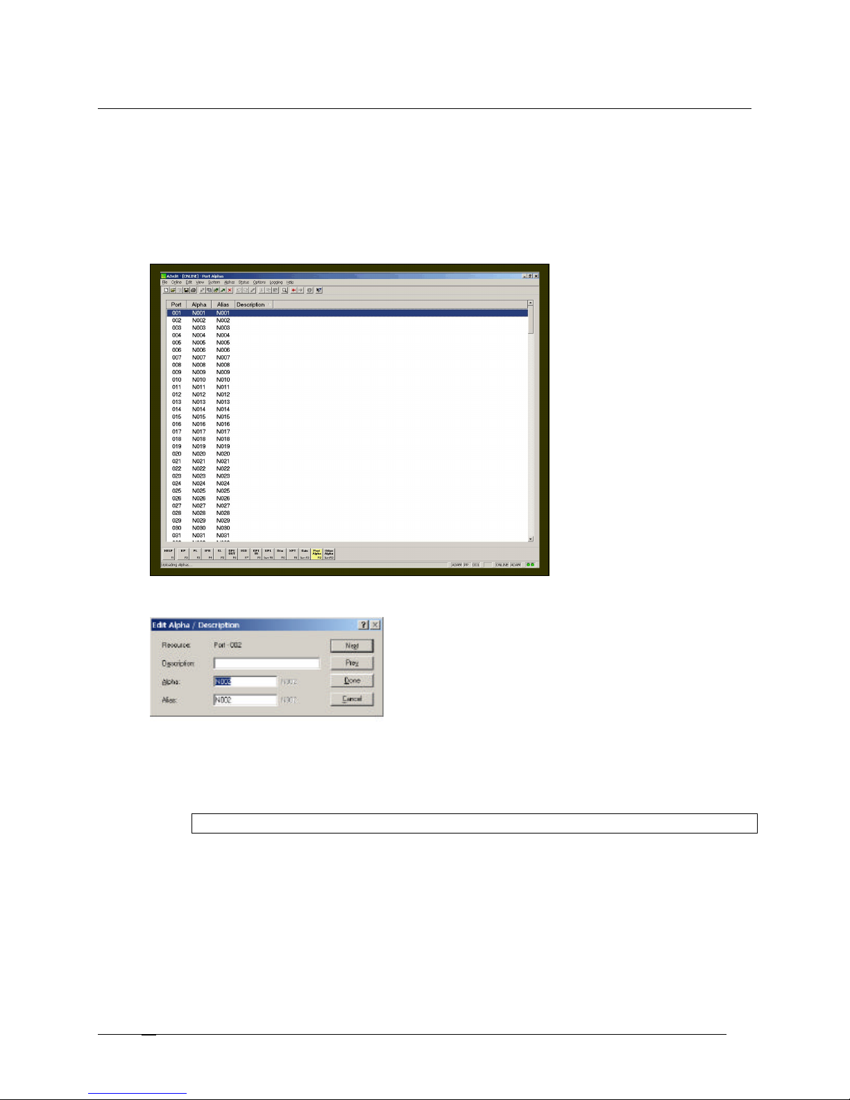
Assigning Alphas (names) to Intercom Ports
Intercom ports have names called Alphas. As a default, they have generic names, such as N001, N002, etc. Alphas
appear in the alphanumeric displays on keypanels equipped with displays. It is recommended you change the default
alphas to names more meaningful to your keypanel operators. You can also add brief descriptions to the Alphas to
further describe the port and help to distinguish for what the intercom port is being used.
To assign alphas to intercom ports, do the following:
1. From the Keypanel / Port screen, click Port Alpha.
The Port Alphas screen appears.
2. Double-click the port for which you want to change the default alpha.
The Edit Alpha Description screen appears.
3. In the Description field, enter a description of the Port.
There is a 24-character limit on this field.
4. In the Alpha field, enter an alpha for the port.
There is a 4-character limit on this field.
Note: The Alpha and Alias fields will be the same, unless you change the Alias field manually.
5. In the Alias field, enter an alias for the port, if necessary.
There is a 4-character limit on this field.
For more information on Alpha vs. Alias, see the screen description for Alpha and Alias.
Telex Communications
50
Page 51

Alternative Method of Assigning Alpha
If you want to change the name for a particular intercom port while you are viewing the keypanel setup screen for that
port, you can use this method for assigning Alphas. However, it is not recommended for assigning multiple alphas to
the intercom system.
To assign alphas to a port while viewing the keypanel setup screen, do the following:
1. While viewing the keypanel setup screen, press Ctrl + F12.
The Edit Alpha Description screen appears.
2. In the Description field, enter a description of the Port.
There is a 24-character limit on this field.
3. In the Alpha field, enter an alpha for the port.
There is a 4-character limit on this field.
Note: The Alpha and Alias fields will be the same, unless you change the Alias field manually.
4. In the Alias field, enter an alias for the port, if necessary.
There is a 4-character limit on this field.
For more information on Alpha vs. Alias, see the screen description for Alpha and Alias.
Telex Communications
51
Page 52
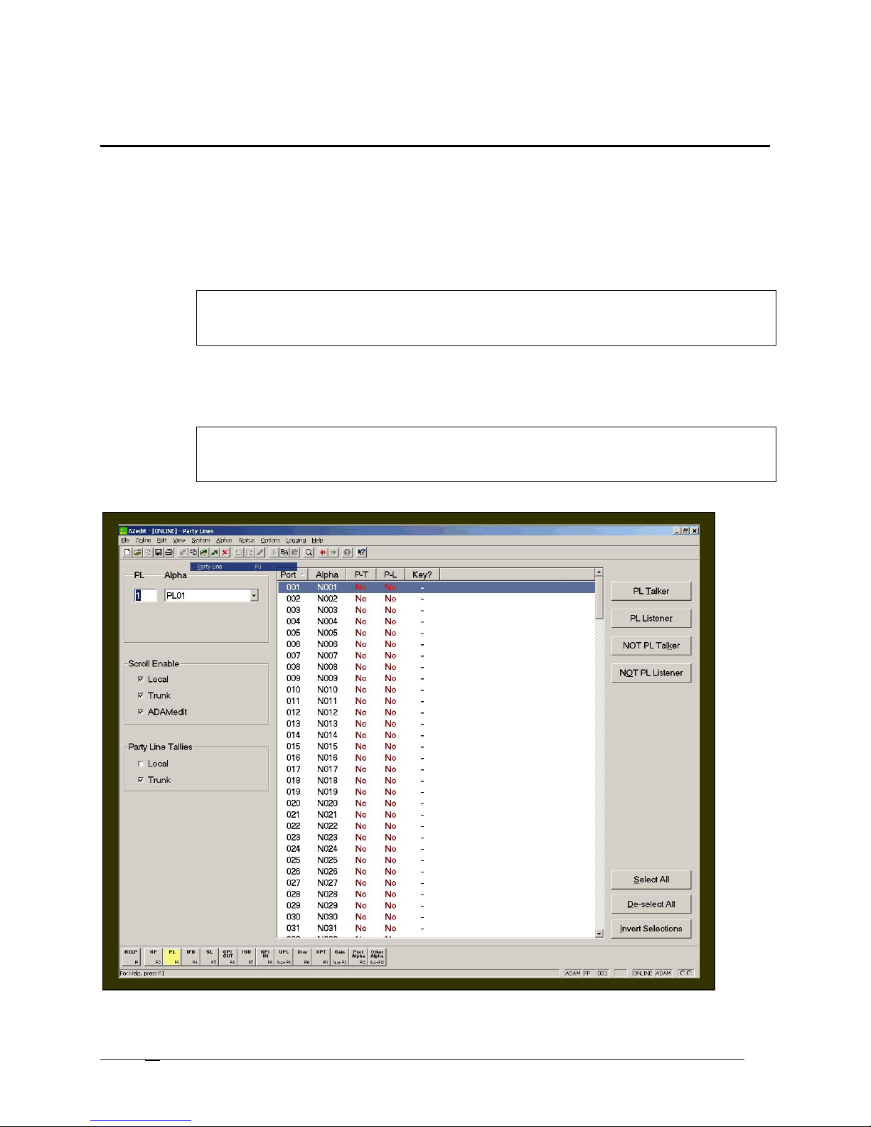
Party Lines
A party line, also called a conference line, is a group of intercom ports that can talk and/or listen to each other. Party
lines have default names such as, PL01, PL02, etc… These names can be changed using the Other Alpha setup
screen (for more information, see Other Alphas). Members of a party line are assigned using the Party Line setup
screen. Once the party line is established, it can be assigned to a keypanel using the Keypanel setup screen (for
more information, see Keypanels). When a party line is assigned to a keypanel key, this allows the keypanel operator
to talk and/or listen to the party line without being a member.
Important: Do not confuse party lines with special lists. A special list is used when a keypanel
operator needs to listen or talk to a group of intercom panels that are not related. Basically, this is a
grouping between keypanel type users.
Party lines are typically used when several users of non-keypanel devices (such as, belt packs or cameras) are used
in a specific common activity and need to talk/listen to each other constantly. Keypanels are never permanent
members of party lines. However, a keypanel key can be assigned to occasionally talk or listen to a party line, if
desired. In party lines, several ports can be made members of the same party line, if needed.
Note: Party lines are primarily set up for party line members, with occasional access by keypanel
operators, while special lists are set up mainly for keypanel operators to talk or listen to several
unrelated intercom ports.
Telex Communications
52
Page 53
Screen Items
1. Click
NOT PL Talker
to deselect the port assignment as a
Screen Item Field Description
PL text box
The PL box shows the number of the party line for which you want to
view.
Alpha drop-down list
The Alpha drop-down list shows the alpha name assigned to the party
line.
1. From the Alpha drop-down list, select the Alpha for
which you want to work.
Port column display
Alpha column display
The Port column displays the port available to assign to the party line.
The Alpha column displays the alpha name of the port available to assign
to the party line selected.
P-T column display
The P-T column displays the ports that are assigned as permanent
talkers. This means that the port can only send out signals and not
receive. The permanent talker assignment is only used with devices that
cannot instruct the intercom system on how to route the audio.
Yes indicates the given port transmits audio to the currently viewed party-
line system.
No indicates the given port does not transmit audio to the currently viewed
party line system.
P-L column display
The P-L column displays the Permanent Listener status for each port in
the system. This means that the port can only receive audio signals.
Yes indicates the given port receives audio from the currently viewed
party line.
No indicates the given port does not receive audio from the currently
viewed party line.
Key? Column display
The Key? Column displays when an intercom keypanel is talking or
listening to the party line using intercom keys. This column is refreshed
(updated with current information) frequently during normal operation.
Note: To force a refresh, either select Refresh from the
View menu; or press Ctrl+Space.
Talk: The port has a talk key pressed to talk to the party line.
Listen: The port has a listen key pressed to listen to the party line.
Both: The port has both a talk and listen key pressed for 2-way
communication with the party line.
PL Talker button
Use the PL Talker button to designate selected ports as permanent
talkers for the currently viewed PL assignment. Party Line Talker
assignments are only used with devices that cannot instruct the intercom
system on how to route the audio. This option is usually not used with
keypanels.
1. Click PL Talker to make the selected port(s) permanent talkers
(P-T) for the currently viewed PL assignment.
PL Listener button Use the PL Listener button to designate selected ports as permanent
listeners for the currently viewed PL assignment. Party Line Listener
assignments are only used with devices that cannot instruct the intercom
system on how to route the audio. This option is usually not used with
keypanels.
1. Click PL Listener to make the selected port(s) permanent
listeners (P-L) for the currently viewed PL assignment.
NOT PL Talker button
Use the NOT PL Talker button to deselect a port or ports as permanent
talkers for the currently viewed PL assignment.
Telex Communications
53
Page 54
NOT PL Listener button
SCROLL ENABLE
Scroll enable check boxes appear in the setup views for the following destination types: intercom
ports, party lines, IFB's, Special Lists, GPI Outputs, UPL Resources, and ISO's. The Scroll Enable
check boxes controls who can view destinations in scroll lists and assign those destinations to
keypanel keys. When you are using AZedit within your own intercom system, you always have access
to the complete scroll lists. However, access for everyone else is controlled as follows:
Local check box
Trunk check box
AZedit check box
PARTY LINE TALLIES
Local check box
permanent talker.
Use the NOT PL Listener button to deselect a port or ports as permanent
listeners for the currently viewed PL assignment.
1. Click NOT PL Listener to deselect the port assignment as a
permanent listener.
If Local is checked, any keypanel operator in your intercom system that
has a programmable keypanel can find the destination name in a scroll list
and assign it to a key. If you remove this check mark and send the change
to the intercom system, keypanel operators will not see the destination
name in their scroll lists, and therefore, will not be able to assign it to a
key. They will also not be able to assign it using keypad numeric entry
(KP9X series keypanels). And, if the destination name appears in any
display on their keypanel, they will not be able to copy it to any other key.
The Trunk check box is only selectable if trunking has been activated. If
you place a check mark here, any keypanel operator in a remote intercom
system that has a programmable keypanel can view the destination in a
scroll list and assign it to a key on their keypanel. If you remove this check
mark and send the change to the intercom system, remote keypanel
operators will not be able to view the destination or assign it to a key by
any means.
The AZedit checkbox is also only selectable if trunking has been
activated. If you place a check mark here, an AZedit user in a remote
intercom system will be able to view the destination in a scroll list and
assign it to keypanel keys in the remote intercom system. If you do not
want remote AZedit users to have access, remove the check mark and
send the change to the intercom system.
Use Local Party Line Tallies when two or more keypanels have keys
assigned to the same party line within the same Intercom system.
Note: Typically, the tally indication is in the form of a
flashing alphanumeric display (KP9x series keypanels)
or a continuously lit, red LED talk key indicator (most
other keypanels). The tally indication tells the keypanel
operator that activating the party key will break in on a
conversation this is in progress.
Trunk check box Use Trunk Party Line Tallies when two or more keypanels have keys
Select All button
De-select All button
Telex Communications
54
assigned to talk to the same party line across remote Intercom systems.
Note: Typically, the tally indication is in the form of a
flashing alphanumeric display (KP9x series keypanels)
or a continuously lit, red LED talk key indicator (most
other keypanels). The tally indication tells the keypanel
operator that activating the party key will break in on a
conversation this is in progress.
Selects all list items in the current view.
1. Click Select All to select all the items in the current view.
De-selects all list items in the current view that are selected.
Page 55
1. Click De-select All to de-select all ports in the current screen
Go Forward
: lets you go forward ag
ain when you have
view.
Invert Selection button
The Invert Selections button reverses the order in which the list is
currently displayed.
1. Click Invert Selection to reverse the list of ports from the current
view.
Right Click Guide to the Party Lines Screen
Built into AZedit are many different ways to get to the same information, by buttons, menus, and right-clicking. The
following is a list of menus and screens you can access by right clicking from the Party Line main screen.
Right-Click Action Right-Click Result
Highlight Port > Right Click A popup menu appears that gives you the following
options:
Info: The information contained here shows the party line
number. Also, Intercom system name and the party line
alpha will appear in brackets.
PL Talk: designates the port as permanent talkers for the
currently viewed PL assignment.
PL Listener: designates the port as permanent listeners
for the currently viewed PL assignment.
From the Navigation menu, you can:
Open the Party Line Alpha View screen
Open the Keypanel View screen
Adjust the Crosspoint Settings for this port
Open the Crosspoint Volume View screen
Open the Party Line Volume View screen
Open the Port Alpha View screen
From the Changes Menu, you can
Clear all changes to this PL/All PL- this clears all the
changes you have made up to the last Save
performed.
From the Search menu, you can:
Search for panels that have the selected port as a key
assignment.
Search for panels with the selected party line as a key
assignment.
Note: You must be connected to the Intercom
for some of these menus to work.
Right-click anywhere on the screen A popup menu appears that gives you the options to:
Undo: reverses the last action--for example, to undo a
deletion, thus restoring deleted text to a document.
Redo: will redo up to 20 consecutive changes that you
previously canceled with the Undo Button.
Go Back: lets you go back to previously viewed screens
(up to 20).
Telex Communications
55
Page 56

used Go Back to look at previously viewed screens.
Search: From the Search popup menu, you can:
Search for this panel (opens the Search Status Screen)
Search for panels with this key assignment (only
available when a key assignment has been made)(opens
the Search Status Screen)
Show Grid: Opens key assignment grid.
Telex Communications
56
Page 57
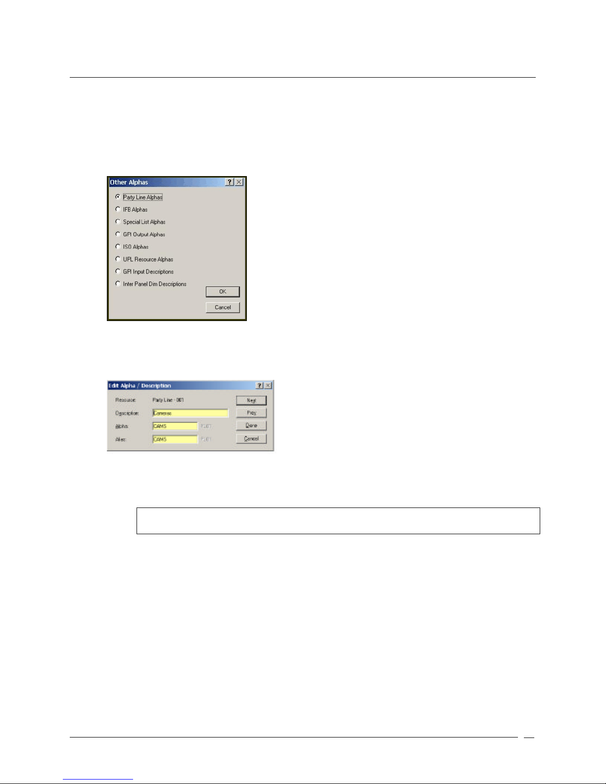
Assigning Alphas to Party Lines
Party lines have default names, such as PL01, PL02 etc. You can change these names to something more
recognizable to keypanel operators. You can also add brief descriptions to help you distinguish between party line
uses.
To assign a party line alpha, do the following:
1. From the Keypanel / Ports screen, click Other Alphas.
The Other Alphas screen appears.
2. Select Party Line Alphas.
The Party Line Alphas screen appears.
3. Double-click the PL port you want to assign an alpha.
The Edit Alpha Description screen appears.
4. In the Description field, enter a description of the party line. There is a 24-character limit to the field.
5. In the Alpha field, enter a meaningful alpha for the PL port (for example, a camera connected to the PL
port, may have a name such as CAMS).
Note: The Alias and Alpha fields populate with the same information. You can change the Alias, if
needed. For more information see, the Port Alphas screen description.
6. Click Done.
The Party Line is renamed.
Telex Communications
57
Page 58
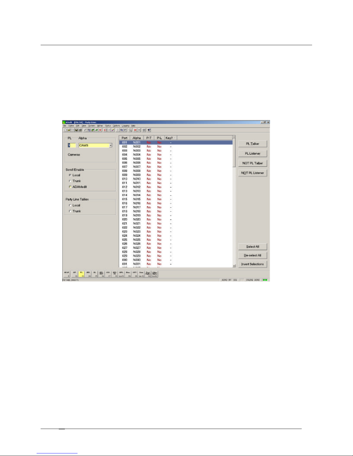
Setting Up a Party Line
Party lines are primarily set up for party line members, with occasional access by keypanel operators. Party lines are
typically used when several users of non-keypanel devices, such as belt packs or cameras, are used in a specific
common activity and need to talk/listen to each other constantly.
To setup a party line, do the following:
1. Start AZedit.
The AZedit application appears.
2. Click the PL button
The Party Line screen appears.
3. Select the Ports connected to the PL (for example, 001).
4. Click PL Talker or PL Listener.
A "Yes" appears in the appropriate column.
For more information on PL Talker and PL Listener, see the Party Line screen description.
Telex Communications
58
Page 59
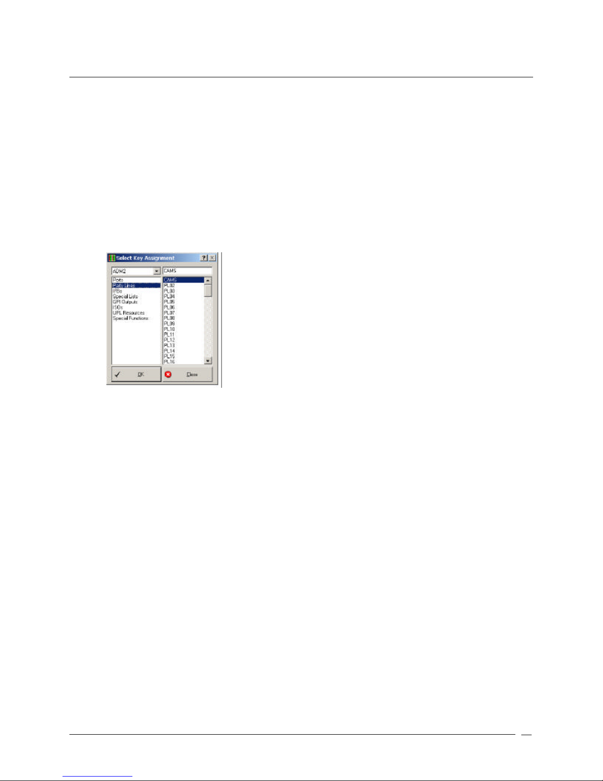
Assign a Party Line to the Keypanel
Once you have assigned ports that can talk or listen to the party line, you can assign it to a keypanel so that users
are able to access the party line.
To assign a party line to the keypanel, do the following:
1. Click the KP button.
The Keypanel / Port screen appears.
2. Right-click a Talk or Listen combo box.
A popup menu appears.
3. Select Change Assignment.
The Select Key Assignment screen appears.
4. From the Key Type List, select Party Line.
All ports assigned to Party Lines appear in the right pane.
5. From the Party Line port list, select the Party Line you want to assign to the keypanel,
Telex Communications
59
Page 60
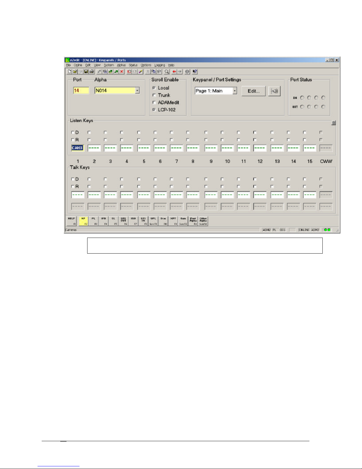
6. Click OK.
The party line alpha appears in the keypanel display field.
Note: Remember; SEND all your changes to the Intercom System before closing the application.
If the changes are not sent they are not saved to the intercom system.
Telex Communications
60
Page 61
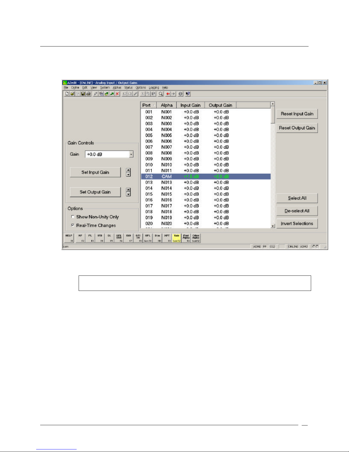
Setting Audio Levels To and From a Party Line
To set audio levels to and from a party line, do the following:
1. From the System menu, select Gains, and then select Analog Input / Output Gains.
The Analog Input / Output Gains screen appears.
2. Highlight the port for which you want to change the audio levels.
3. Using the Set Input Gain and Set Output Gain buttons, adjust the Input and Output levels for the port.
Note: These are initial settings. You can return any time in the future to readjust these settings to
you operational preferences.
Telex Communications
61
Page 62
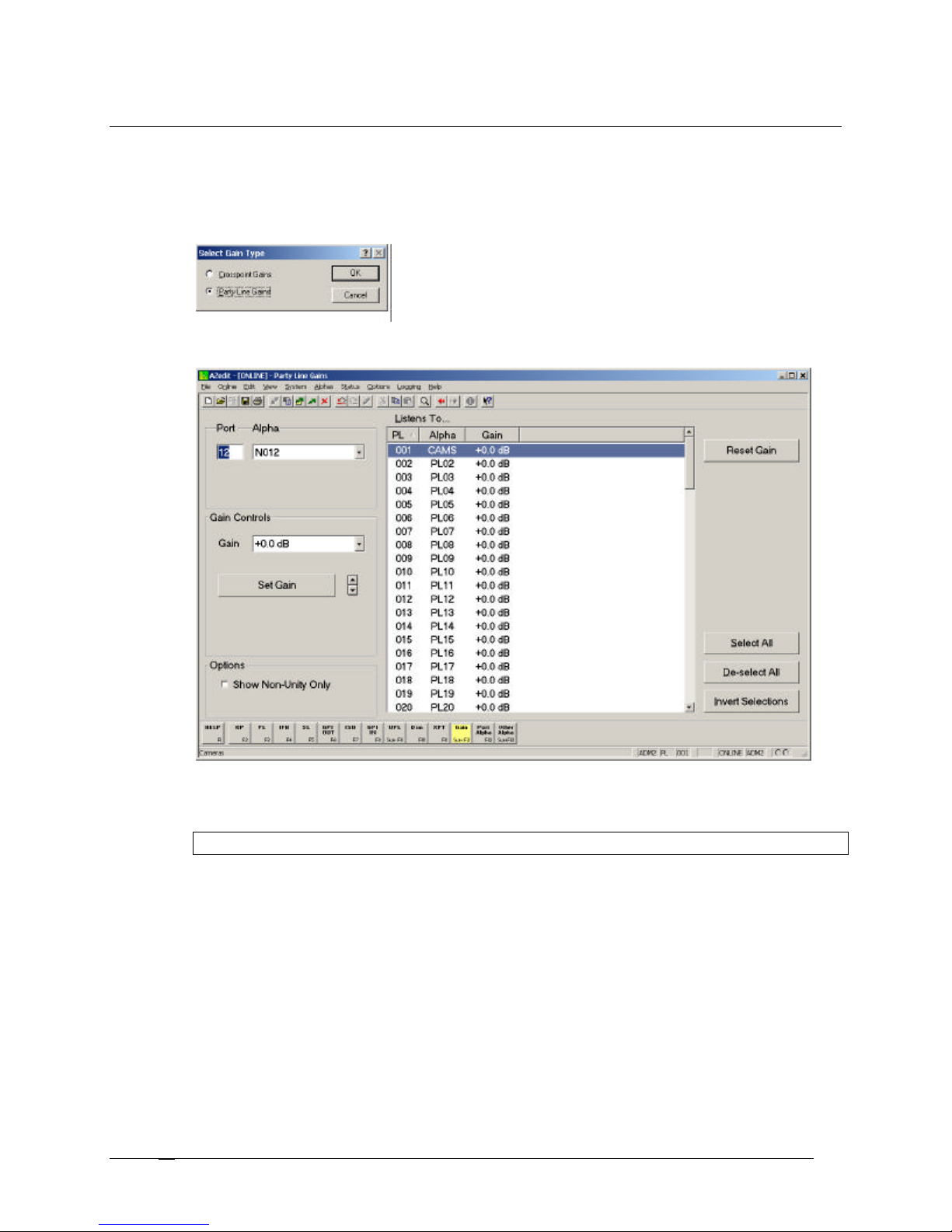
Set Overall PL Gains
This procedure shows you how3 to set overall gain for selected Party Lines.
To set the overall PL gains, do the following:
1. Click Gains.
A popup menu appears.
2. Select PL Gains.
The Party Line Gains screen appears.
3. Select the PL you want to adjust.
4. Using the Gain Controls, adjust the gain for the party line accordingly.
Note: Remember; SAVE all your changes to the Intercom System before closing the application.
Telex Communications
62
Page 63

IFBs (Interrupted Fold Back)
IFB is a method for a keypanel operator to interrupt an audio source that someone is listening to and then talk to that
listener. When the keypanel operator is finished talking and turns off the IFB key, the original audio source "folds
back", or reconnects, to the listener. IFB could be used to interrupt background music on a PA system while someone
is paging. Mostly, though it is used in broadcasting to cue talent, such as news anchors, field reporters, etc.
ADAM and ADAM CS intercom systems are capable of four variations of IFB:
• Standard one-way IFB, where the keypanel operator only needs to talk to the listener.
• Two-way IFB, where the keypanel operator can talk and monitor the talent during IFB operation.
• Two-way IFB, where the keypanel operator can talk and several people can monitor the talent over an
external speaker or other device during IFB operation.
• Tone override IFB, which uses an external control box and a 2400 kHz tone to control IFB operation. This
type of IFB requires specialized equipment and is not generally used.
Screen Items
Screen Item Field Type Description
IFB list column
Telex Communications
Displays the IFB number. This number cannot be changed.
63
Page 64

Alpha list column
DIM list column
LC list column
TK list column
AE list column
Input list column
Alpha list column
Output list column
Alpha list column
Gain list column
However, you can control how many IFB's are available for
use by changing the intercom configuration settings.
The Alpha column displays the name assigned to the IFB.
Default names are IF01, IF02 etc. You can change these
names to ones that are more meaningful to keypanel
operators.
1. Click the row where you want to change the Alpha
name, then press Ctrl + F12.
The Edit Alpha/Description screen appears.
Displays the Dim Level you set in the Edit IFB screen.
No indicates that no dimming values have been set and the
program audio will be completely muted during IFB operation.
The LC column displays the scroll enable settings for the IFB:
LC = Local
TK = Trunk
AE = AZedit
For each type of scrolling, the letters appear green if that type
of scrolling is enabled, and brown (or red when selected) if that
type of scrolling is disabled.
The TK column displays the scroll enable settings for the IFB:
LC = Local
TK = Trunk
AE = AZedit
For each type of scrolling, the letters appear green if that type
of scrolling is enabled, and brown (or red when selected) if that
type of scrolling is disabled.
The AE column displays the scroll enable settings for the IFB:
LC = Local
TK = Trunk
AE = AZedit
For each type of scrolling, the letters appear green if that type
of scrolling is enabled, and brown (or red when selected) if that
type of scrolling is disabled.
The Input column displays the port settings that are set up for
each IFB.
The Alpha column displays the port settings you set up for
each IFB
The Output column displays the port settings you set up for
each IFB
The Alpha column displays the port settings you set up for
each IFB
The Gain column displays the analog output gain for the
intercom port that has been designated as the IFB Output. If
the IFB listening device that is connected to the output port
does not have a volume control, you can adjust the analog
output gain to suit the listener's preference. The analog output
gain be adjusted on the Analog Input / Output Gains screen or
from an LCP-102 that is operating in PAP mode.
NOTE: To access the Edit IFB screen, double-click an IFB from the list, the IFB edit screen will
appear. For more information on the Edit IFB screen, see the AZedit Help file.
Telex Communications
64
Page 65
Right-Click Guide to the IFB Screen
Built into AZedit are many different ways to get to the same information, by buttons, menus, and right-clicking. The
following is a list of menus and screens you can access by right clicking from the IFB main screen.
Right Click Action Result
Highlight Port > Right Click
A popup menu appears that gives you the following
options:
Info: The information contained here shows the IFB
Name, description, default input, output, listen source,
tone override input, and Dim setting.
Scroll Enable: Gives the user the ability to set scroll
enable for Local ports, Trunk ports, AZedit ports.
From the Scroll Enable menu, select Local, Trunk, or
AZedit.
From the Navigation menu, you can:
Go to IFB Priorities View
Go to IFB Listen Source View
Go to IFB Listen Destination View
Go to IFB Alpha View
From the Changes Menu, you can
Clear all changes to this IFB /all IFBs..,.- clears all the
changes you have made up to the last Save
performed.
From the Search menu, you can:
Search for panels with this IFB assigned…
Note: You must be connected to the Intercom
for some of these menus to work.
Right-click anywhere on the screen A popup menu appears that gives you the options to:
Undo: reverses the last action--for example, to undo a
deletion, thus restoring deleted text to a document.
Redo: will redo up to 20 consecutive changes that you
previously canceled with the Undo Button.
Go Back: lets you go back to previously viewed screens
(up to 20).
Go Forward: lets you go forward again when you have
used Go Back to look at previously viewed screens.
Search: From the Search popup menu, you can:
Search for this panel (opens the Search Status Screen)
Search for panels with this key assignment (only
available when a key assignment has been made)(opens
the Search Status Screen)
Show Grid: Opens key assignment grid.
Telex Communications
65
Page 66
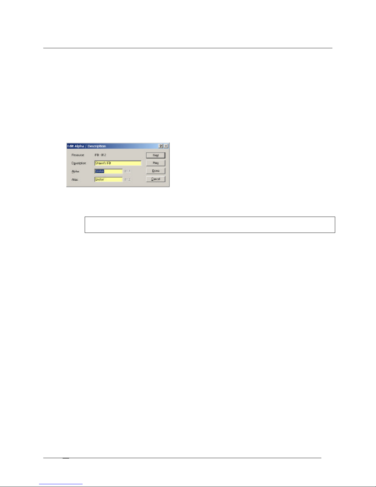
Assign IFB Alphas
IFB Alphas appear in the keypanel display window to whichever key it is assigned.
To assign IFB Alphas, do the following:
1. From the Keypanel / Port screen, click Other Alphas.
The Other Alphas screen appears.
2. Select IFB Alphas.
3. Click OK.
The IFB Alphas screen appears.
4. Double-click the IFB you wish to assign an alpha.
The Edit Alpha Description screen appears.
5. In the Description field, enter a description for the IFB.
6. In the Alpha field, enter a familiar name to recognize the IFB.
Note: The Alias and Alpha fields populate with the same information. You can change the Alias, if
needed. For more information see, the Port Alphas screen description.
7. Click Done.
The IFB is assigned a recognizable alpha.
Telex Communications
66
Page 67
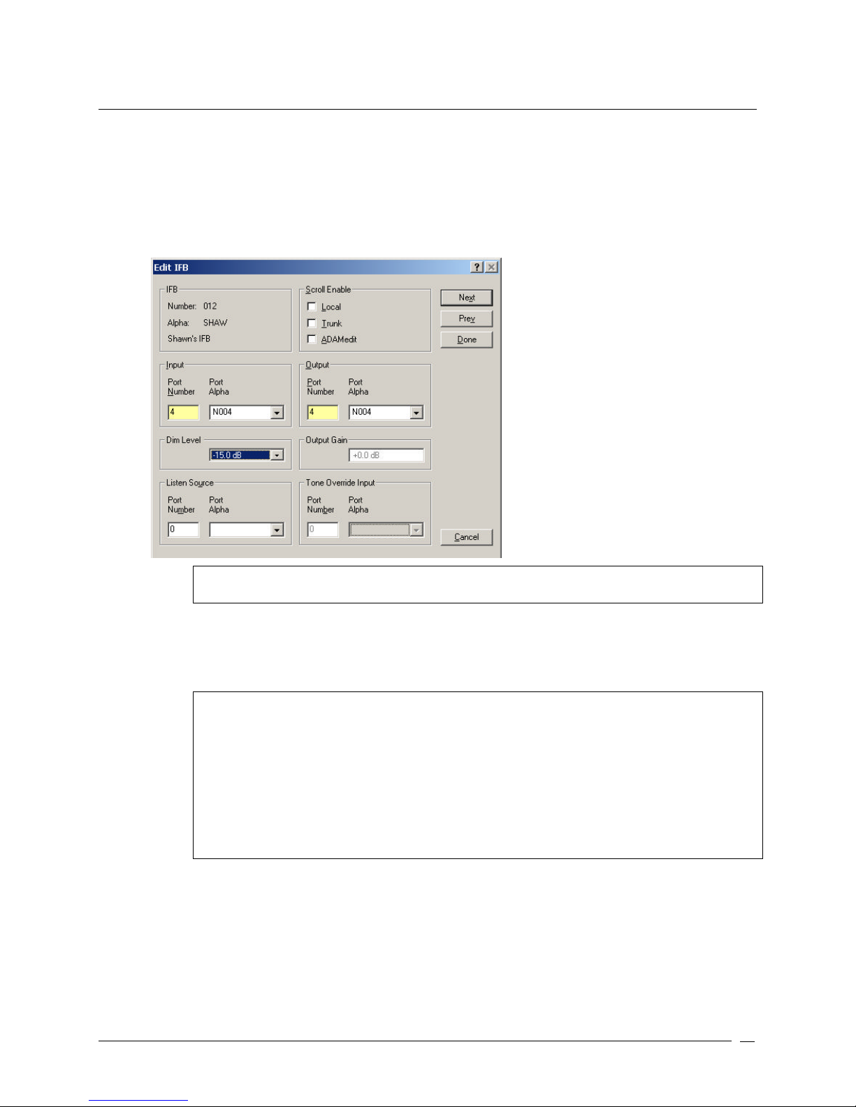
Configure an IFB
To configure an IFB, do the following:
1. Click the IFB button.
The IFB screen appears.
2. From the IFB list, select the IFB you want to configure.
3. Double-click the IFB.
The Edit IFB screen appears.
Note: To restrict keypanel operators from assigning this IFB to keys on their keypanels, make sure
not to select any check boxes under Scroll Enable.
4. In the Input field, enter the port number or select the port alpha of the intercom port where the normal
audio source is connected.
5. In the Output field, enter the port number or select the port alpha of the intercom port where the talent
earset or headset is connected.
Note:
• By default, the audio source is muted while the keypanel operator is talking. If you want to signal
to be diminished by a certain amount during IFB, select a different amount in the Dim Level drop
down list.
• The Listen Source field is only used for 2-way IFB operation. It allows keypanel operators and/or
studio personnel to listen to the talent during IFB Operation. Connect the talent Mic signal (the
direct mic signal, not the mix-minus signal) to an intercom port input. Then, select that port in the
Listen Source field. For more information on Listen Source setup, see Listen Source.
For more information on Tone Override, see Set Tone Override IFB Setup.
6. Click Done.
The changes are made to the screen. However, be sure to save your changes or they will be lost.
Telex Communications
67
Page 68
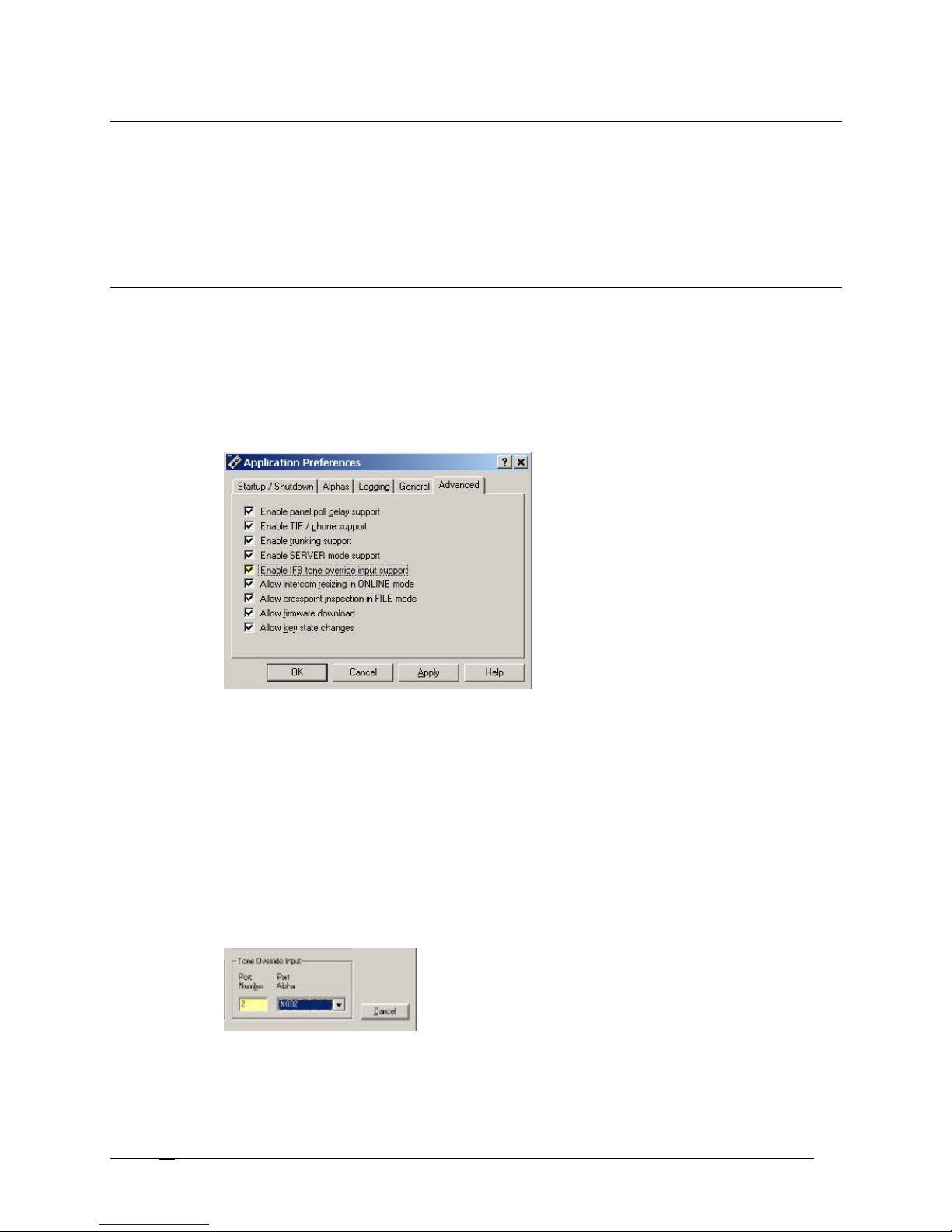
Listen Source
To use the Listen Source feature, a pre-fade mic feed from the talent's mic, through the mix console, and is then
connected to an available input port in the matrix. The port number or alpha is entered on the Edit IFB screen in the
Listen Source Field. Remember; the port alpha for this input source must be entered first under Port Alpha settings.
Verify this port is not a duplicate alpha in the system.
When the listen source is set, go to the keypanel and assign the IFB to a keypanel key. For information on how to
assign an IFB to the keypanel see, Assign an IFB to a Keypanel.
Tone Override IFB Setup
The Tone Override IFB is not used for Standard IFB.
To use tone override IFB setup, do the following:
1. From the Options menu, select Preferences.
The Application Preferences screen appears.
2. Click the Advanced tab.
The Advanced screen appears.
3. Select the Enable IFB tone override input support check box.
4. Click Apply.
The change is applied.
5. Click OK.
The Applications screen closes.
6. Click the IFB button.
The IFB screen appears.
7. Double-click the IFB you want to set tone override IFB.
The Edit IFB screen appears.
8. In the Tone Override field, enter the port number or select the port alpha where the 2400 kHz
tone source is connected.
9. Click Done.
Telex Communications
68
Page 69
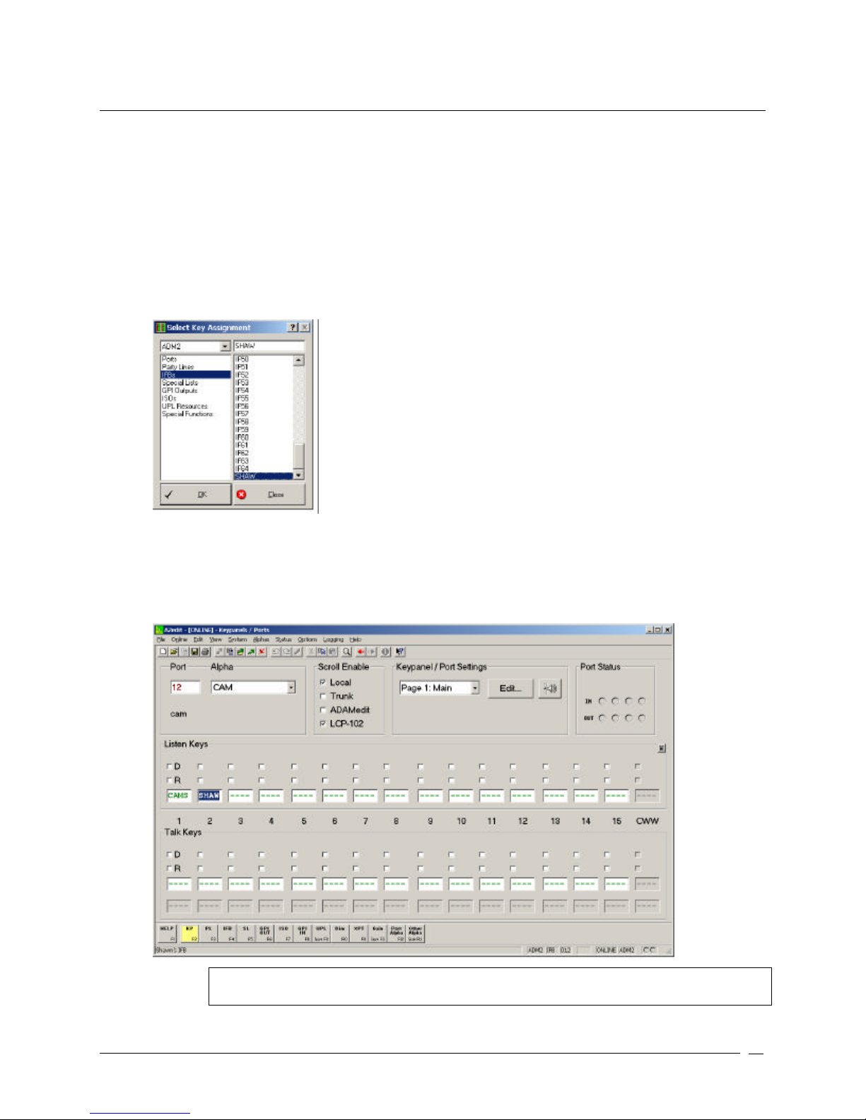
Assign a IFB to the Keypanel
Once you have assigned ports that can talk or listen to the party line, you can assign it to a keypanel so that users
are able to access the party line.
To assign a party line to the keypanel, do the following:
1. Click the KP button.
The Keypanel / Port screen appears.
2. Right-click a Talk (or Listen) combo box.
A popup menu appears.
3. Select Change Assignment.
The Select Key Assignment screen appears.
4. From the Key Type List, select IFBs.
All ports assigned to IFBs appear in the right pane.
5. From the IFB port list, select the IFB you want to assign to the keypanel,
6. Click OK.
The IFB alpha appears in the keypanel display field.
Note: Remember; SEND all your changes to the Intercom System before closing the application.
If the changes are not sent they are not saved to the intercom system.
Telex Communications
69
Page 70
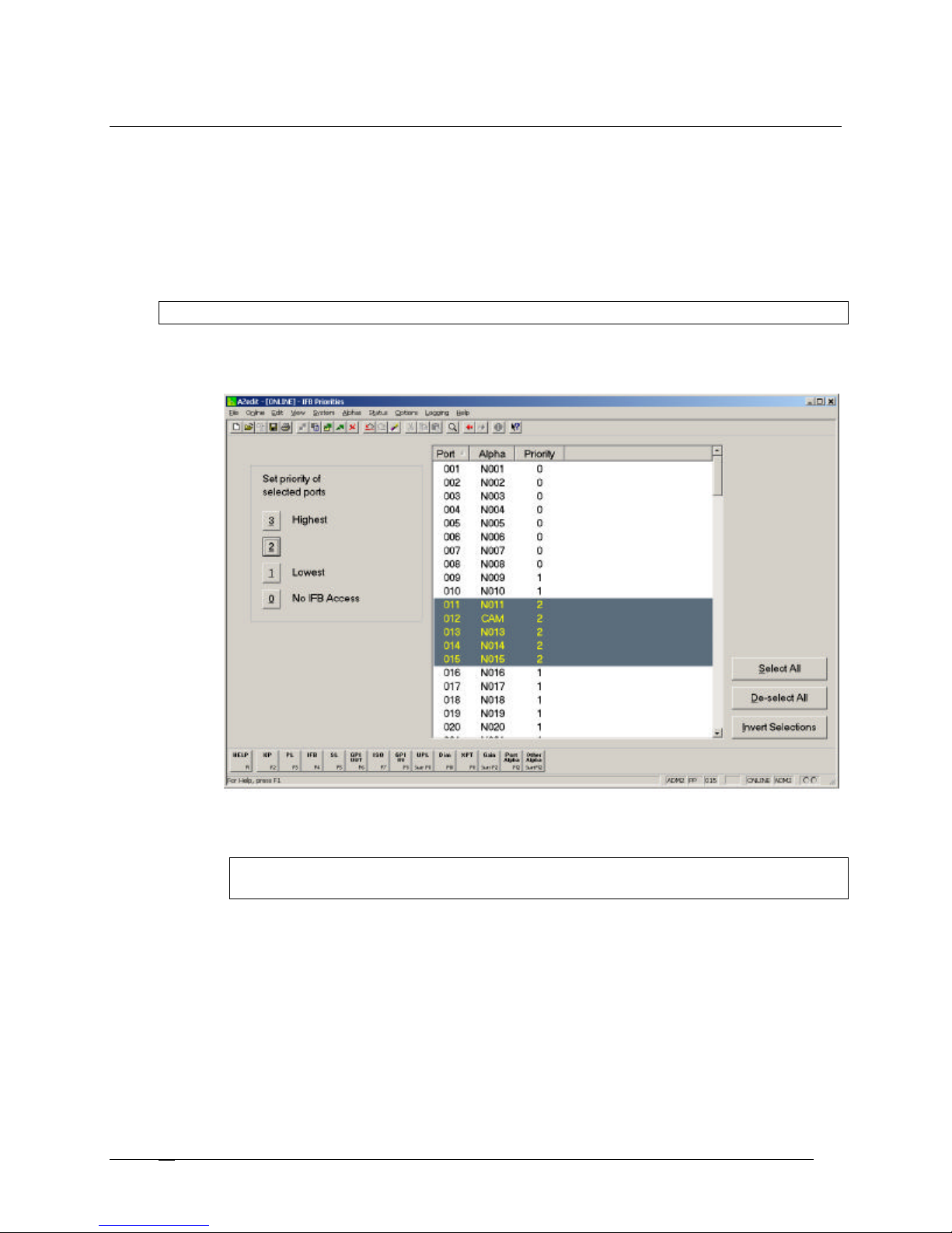
IFB Priority Setup
Set the IFB priority when you want to give one user access to the IFB over another user. For example, a director
and an assistant can be setup to communicate with the same IFB. If IFB priority has been set, giving the director a
higher priority than the assistant. Anytime the assistant is communicating with the IFB and the director wants to talk to
the IFB, the assistant will be cut off from the IFB and see a busy signal (double asterisks) on the keypanel display
until the director is finished talking to the IFB.
The default IFB priority setting for all users is one. You can configure the maximum priority level (up to 8 levels). For
more information on how to configure priority levels, see Configure System IFB Priority Levels.
Note: A priority of zero does not allow a port the ability to interrupt an IFB if it is talking with a higher priority.
To set IFB priority for multiple ports, do the following:
1. From the System menu, select IFB Priority.
The IFB Priority screen appears.
2. From the Port list, select the ports you want to set the IFB priority.
3. Under Set priority of selected ports, select the priority to set the ports (for example, 2).
Note: Remember; SEND all your changes to the Intercom System before closing the application.
If the changes are not sent they are not saved to the intercom system.
To set IFB priority for individual ports, do the following:
1. On the Keypanel / Port screen, select the port for which you want to set the priority.
2. Click Edit.
The Keypanel / Port Configuration screen appears.
Telex Communications
70
Page 71
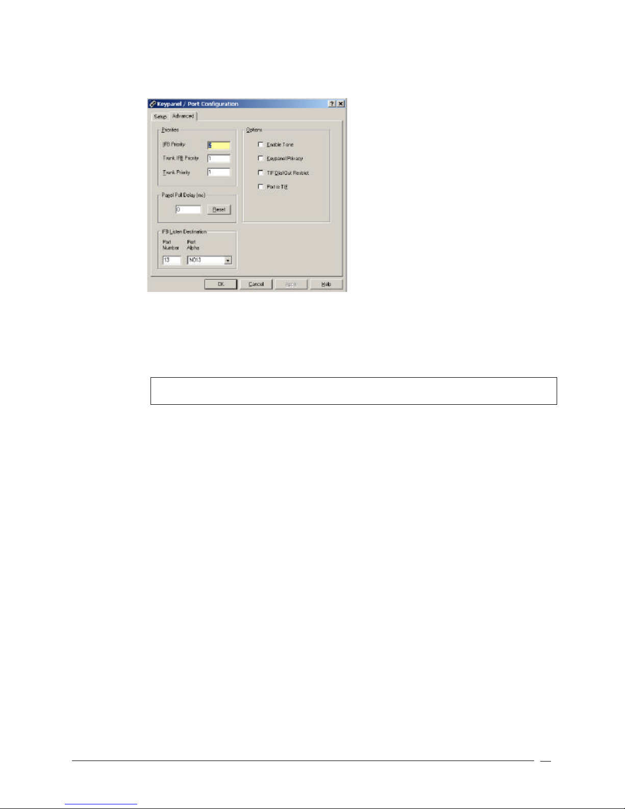
3. Click the Advanced tab
The Advanced screen appears.
4. In the IFB priority field, enter the priority you want to assign to the individual port.
5. Click Apply.
The changes are applied to the application.
6. Click OK.
The Keypanel / Port Configuration screen closes and the priority is set.
Note: Remember; SEND all your changes to the Intercom System before closing the application.
If the changes are not sent they are not saved to the intercom system.
Telex Communications
71
Page 72
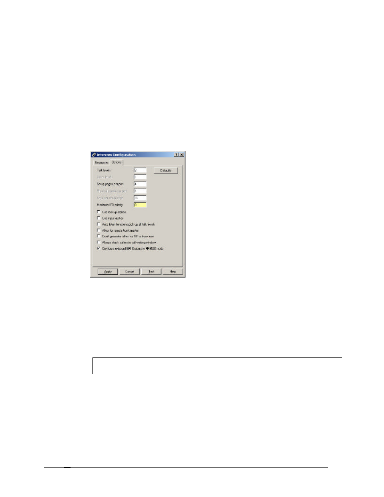
Configure System IFB Priority Levels
By default, the IFB priority level ranges from one to three (one being the lowest priority). However, if your application
needs to support more than three priority levels, you can configure the system IFB priority level as high as a level
eight priority.
To configure the IFB priority level, do the following:
1. From the Options menu, select Intercom Configuration.
A Warning screen appears. Be sure to read this carefully.
2. Click OK. Otherwise, click Cancel.
The Intercom Configuration screen appears.
3. Click the Options tab
The Options screen appears.
4. In the Maximum IFB priority field, enter the maximum priority level you want (up to level eight).
5. Click Apply.
A warning indicating that you are changing the intercom configuration appears.
6. Click OK.
A message indicating, "Would you like to make this configuration the AZedit default?" appears.
7. Click Yes, to make the setting the default and close the Options screen.
Click No, to cancel the changes and close the Options screen.
Click Cancel, to cancel the configuration change, but not close the Options screen.
Note: Remember; SEND all your changes to the Intercom System before closing the application.
If the changes are not sent they are not saved to the intercom system.
Telex Communications
72
Page 73
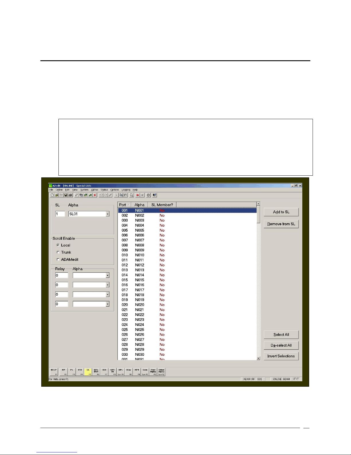
Special Lists
A special list is a group of intercom ports a keypanel operator can talk or listen to by activating a single key. Special
lists are typically used for paging, all call, group call, etc. Special lists have default names such as SL01, SL02, etc.
The names can be changed to more meaningful names by using the Other Alpha setup screen. Members of a
Special List are defined through the Special List setup screen. Once a special list has been set up, typically keypanel
keys can be configured using Keypanel setup. Once the keypanels are setup, then a keypanel operator can activate
the special list key to talk or listen to all members of the special list.
IMPORTANT: Do not confuse special lists and party lines. A special list is used when a keypanel operator
needs to occasionally talk or listen to a group of intercom ports that are otherwise unrelated. A party line is
used when several users of non-keypanel devices (such as belt packs or camera intercoms) are engaged in
a specific common activity and need to talk and/or listen to each other all the time. Keypanels are almost
never members of party lines. However, a keypanel key can be assigned to occasionally talk or listen to a
party line, if desired. Party lines are primarily set up for party line members, with occasional access by
keypanel operators; while special lists are set up exclusively for keypanel operators to talk or listen to
several unrelated intercom ports.
Telex Communications
73
Page 74
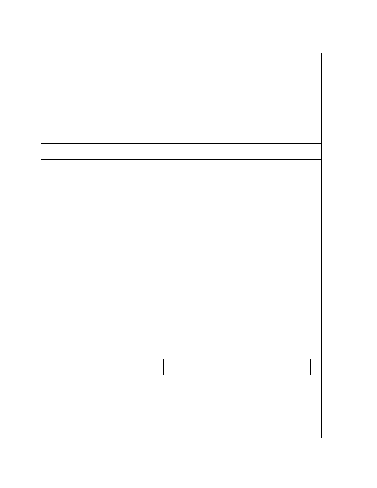
Screen Items
Screen Item Field Type Description
SL text box
Displays the SL number assigned to the Special List being
viewed.
Alpha drop-down box
Indicates the Alpha assigned to the Special List being viewed.
To change the Special List being viewed, do the following:
1. From the Alpha drop-down list, select the Alpha of
the Special List you want to view.
The information of the Alpha you select appears.
Port list column
The Port column displays a list of ports within the intercom
system.
Alpha list column
The Alpha column displays a list of alphas within the intercom
system.
SL Member? list column
The SL Member? column indicates whether the selected port
is a member of the special list currently being viewed.
Scroll Enable check box Scroll enable check boxes controls who can view destinations
in scroll lists and assign those destination to keypanel keys.
When using AZedit within your own intercom system, access
to the complete scroll lists is always available. However,
access for everyone else is controlled as follows:
Local: If Local is checked, any keypanel operator in the
intercom system that has a programmable keypanel can find
the destination name in a scroll list and assign it to a key. If
the checkbox is not selected, keypanel operators will not see
the destination name in their scroll lists, and therefore, will not
be able to assign it to a key. They will not be able to assign it
using a keypad numeric entry (KP9x series keypanels). And, if
the destination name appears in any display on their keypanel,
they will not be able to copy it to any other key.
Trunk: The Trunk checkbox is only selectable if trunking is
activated. If the Trunk checkbox is selected, any keypanel
operator in a remote intercom system that has a
programmable keypanel can view the destination in a scroll list
and assign it to a key on their keypanel. If this checkbox is not
selected, remote keypanel operators cannot view the
destination or assign it to a key on their keypanel.
AZedit: The AZedit check box is only selectable if trunking has
been activated. If the check box is selected, an AZedit user in
a remote intercom system will be able to view the destination
in a scroll list and assign it to keypanel keys in the remote
intercom system. If the check box is not selected, AZedit users
will not have access to view and assign keypanel keys.
Note: To turn off the Scroll Enable check boxes for all
intercom ports, party lines, etc., see Scroll Enable setup.
Relay / Alpha text box and drop
down box
Add to SL button
Telex Communications
74
The Relay text box displays the number assigned to the
selected GPI Output. Relays are optional in special lists. If a
relay is selected, the relay will close when the special list
currently being viewed is activated from a keypanel.
The Alpha drop down list contains the alpha or name
assigned to the selected relay.
The Add to SL button removes the selected port(s) from the
special list.
Page 75
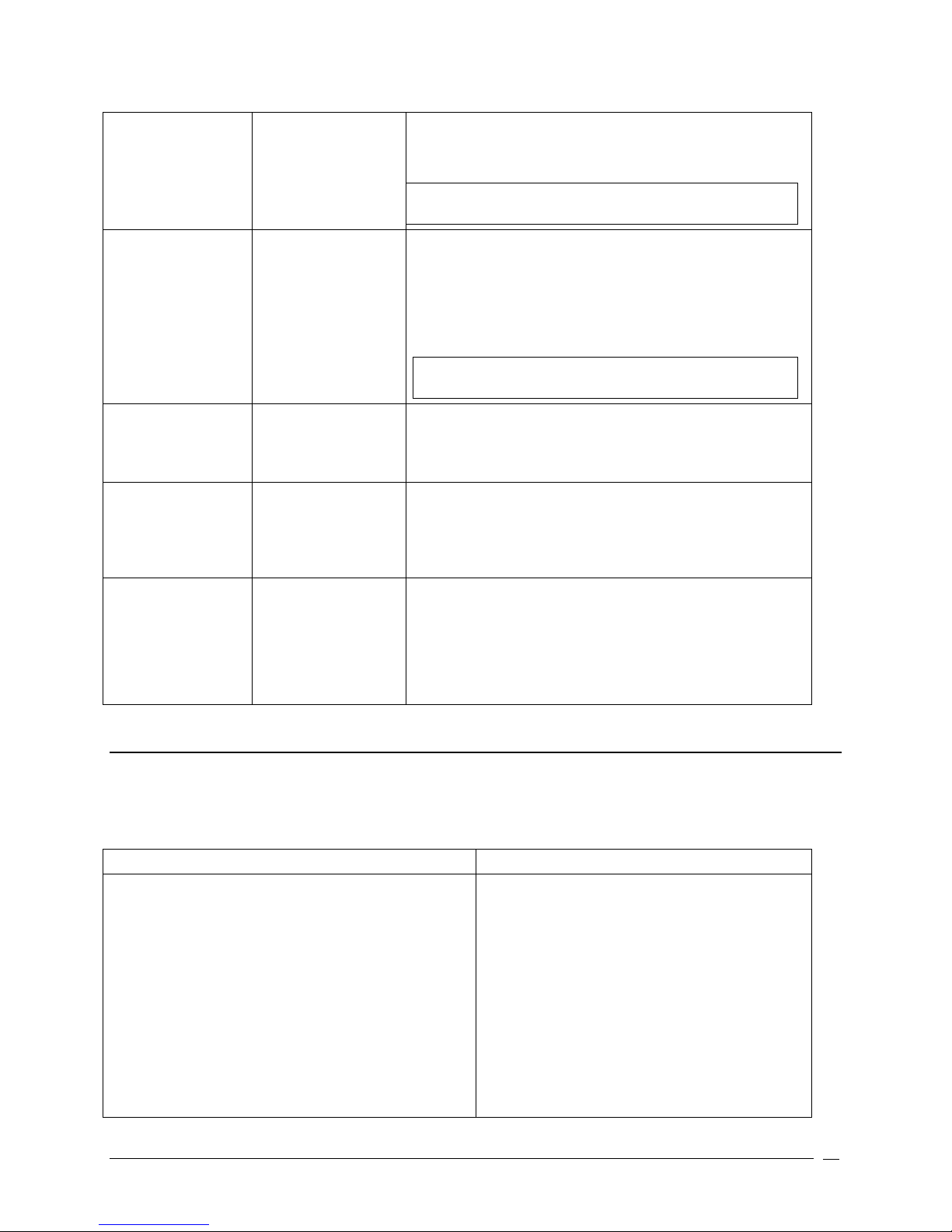
1. Highlight the port(s) you want to remove from the
Go to Keypanel View
special list, and then click Add to SL.
The port(s) you highlighted is added to the special list
and YES appears in the SL Member? column.
Note: To select multiple ports, press the Ctrl key, and then
select the ports.
Remove from SL button
Select All button
De-select All button
Invert Selection button
The Remove from SL button removes the selected port(s)
from the special list.
1. Highlight the port you want to remove from the
special list, and then click Remove from SL.
The port(s) you highlighted is removed from the
special list and NO appears in the SL Member?
column.
Note: To select multiple ports, press the Ctrl key, and then
select the ports.
The Select All button selects all the available ports in the Port
list.
1. Click Select All.
All the ports in the port list are highlighted.
The De-select All button removes the select highlight from the
all the ports in the port list.
1. Click De-select All.
All the ports highlighted in the port list are
deselected.
The Invert Selection button reverses the selections made.
For example, if 3 ports are highlighted, and Invert Selection is
clicked, the three ports that were highlighted are no longer
highlighted while the rest of the port list becomes highlighted.
1. Click Invert Selection.
The highlighted ports are no longer highlighted, while
ports that were not highlighted become highlighted.
Right-click guide to the SL screen
Built into AZedit are many different ways to get to the same information, by buttons, menus, and right-clicking. The
following is a list of menus and screens you can access by right clicking from the SL main screen.
Right-Click Action Result
Highlight Port > Right Click
Telex Communications
A popup menu appears that gives you the following
options:
Info: The information contained here shows the
Special List Name, description, the number of
members for the special list, selected port, and the
description of the port.
Member: Gives the user the ability to select or deselect a port for the Special List.
From the Navigation menu, you can:
Go to Special Lists Alpha View
75
Page 76
Adjust Crosspoint Settings for this Port
Go to Crosspoint Volume View
Go to Party Line Volume View
Go to Port Alpha View
From the Changes Menu, you can
Clear all changes to this SL /all SLs..,.- clears all
the changes you have made up to the last Save
performed.
From the Search menu, you can:
Search for panels with this port alpha as a key
assignment.
Search for panels with this special list alpha as
a key assignment.
Note: You must be connected to
the Intercom for some of these
menus to work.
Right-click anywhere on the screen A popup menu appears that gives you the options
to:
Undo: reverses the last action--for example, to
undo a deletion, thus restoring deleted text to a
document.
Redo: will redo up to 20 consecutive changes that
you previously canceled with the Undo Button.
Go Back: lets you go back to previously viewed
screens (up to 20).
Go Forward: lets you go forward again when you
have used Go Back to look at previously viewed
screens.
Search: From the Search popup menu, you can:
Search for this panel (opens the Search Status
Screen)
Search for panels with this key assignment (only
available when a key assignment has been
made)(opens the Search Status Screen)
Show Grid: Opens key assignment grid.
Telex Communications
76
Page 77
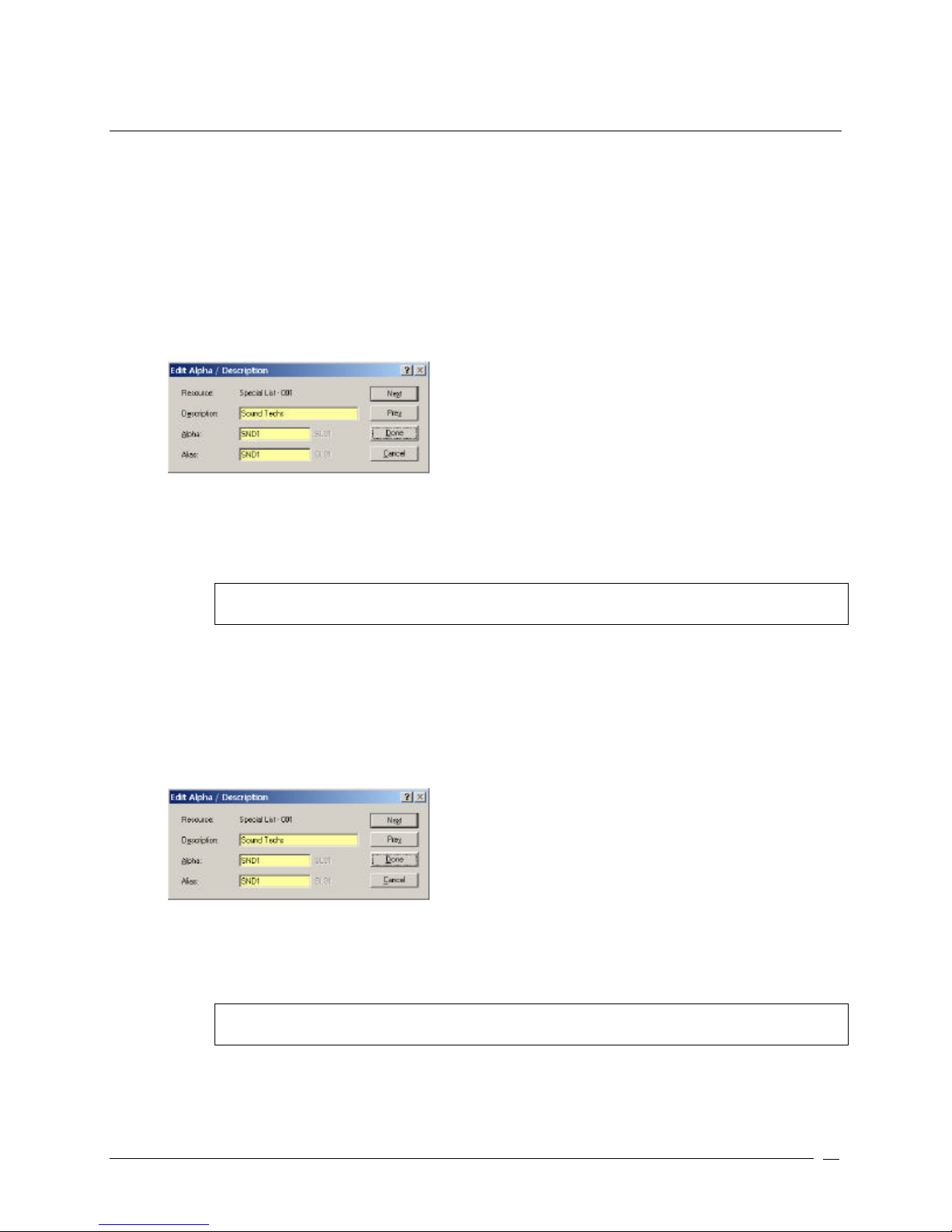
Assign Special List Alphas
Special lists have default names, SL01, SL02, etc. You can change the defaults to more meaningful names. You can
also enter a brief description to give further information and keep track of the special lists that you use.
To assign alphas to multiple special lists, do the following:
3. In AZedit, click Other Alphas.
The Other Alphas screen appears.
4. From the Other Alphas screen, select Special List Alpha.
The Special List Alpha screen appears.
5. Double-click a Special List.
The Edit Alpha Description screen appears.
6. In the Description field, enter a description of the special list (for example, Sound Techs). The description
field has a 24-character field limit.
7. In the Alpha field, enter a meaningful name that users would recognize for the special list (for example,
SND1). The Alpha and Alias fields have 4-character field limits.
Note: The Alias and Alpha fields populate with the same information. You can change the Alias, if
needed. For more information see, the Port Alphas screen description.
8. Click Next to assign another alpha. Otherwise, click Done.
The Special List default alpha is changed.
To assign a special list alpha during the special list setup, do the following:
1. In AZedit, click SL.
The Special Lists screen appears.
2. Press Ctrl + F12.
The Edit Alpha Description screen appears.
9. In the Description field, enter a description of the special list (for example, Sound Techs). The description
field has a 24-character field limit.
10. In the Alpha field, enter a meaningful name that users would recognize for the special list (for example,
SND1). The Alpha and Alias fields have 4-character field limits.
Note: The Alias and Alpha fields populate with the same information. You can change the Alias, if
needed. For more information see, the Port Alphas screen description.
11. Click Done.
The Special List default alpha is changed.
Telex Communications
77
Page 78

GPI Out
ADAM and ADAM CS intercom systems have a General Purpose Interface (GPI) port. GPI ports have eight control
outputs (also referred to as relays) and eight control inputs. The location of the GPI port on the ADAM and ADAM CS
is as follows:
ADAM: Located on XCP-ADAM-MC Master Controller Breakout Panel, J11.
ADAM CS: Located on ADAM CS back panel, J903.
GPI Port Pin-out
All 25-pin GPI Port connectors have the same pin-out as follows:
Pin No. Function:
1. GPI In #1 (+5 to +18 VDC)
2. GPI In #2 (+5 to +18 VDC)
3. GPI In #3 (+5 to +18 VDC)
4. GPI In #4 (+5 to +18 VDC)
5. GPI In #5 (+5 to +18 VDC)
6. GPI In #6 (+5 to +18 VDC)
7. GPI In #7 (+5 to +18 VDC)
8. GPI In #8 (+5 to +18 VDC)
9. Common
10. Common
11. Common
12. Common
14. GPI Out #1
15. GPI Out #2
16. GPI Out #3
17. GPI Out #4
18. GPI Out #5
19. GPI Out #6
20. GPI Out #7
21. GPI Out #
22. Common
23. Common
24. Common
25. Common
13. Common
GPI Inputs for UIO-256, ADAM, and ADAM CS: Connect +5 to +18 VDC between any GPI input and common to
activate that GPI input.
GPI outputs UIO-256: Activating a GPI output causes a relay contact closure between that output and common. The
relay contacts are rated for 0.5A at 120 VAC; 1A at 24 VDC; 0.3A at 60 VDC.
GPI Outputs for ADAM and ADAM CS: Activating a GPI output causes an active high output. This can be changed
to active low by going to the Options menu and selecting Intercom Configuration (on the Options sheet, select the
Configure onboard GPI Outputs in FR9528 mode).
GPI Outputs
Also, referred to as Relays, GPI Outputs can be used to activate external devices directly from keypanel keys. For
example, an external lighting control device can be activated from a keypanel key. A GPI Output can also be set up to
activate when a person talks to a certain port. For example, connect a 2-way radio to an intercom port and then set
up a GPI output to activate whenever anyone talks into the transmitter. GPI Outputs can also be used to activate
Telex Communications
78
Page 79
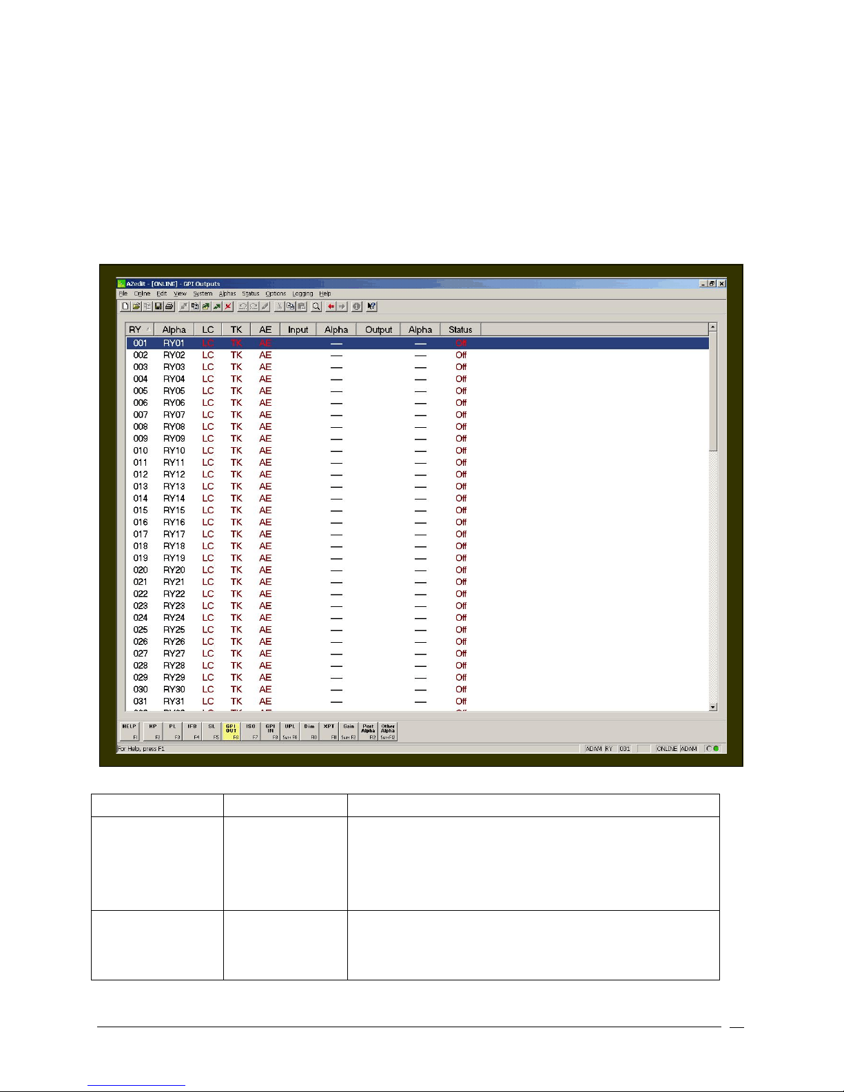
external devices from User Programming Language (UPL) statements. For example, you can set up a UPL state that
1. Select a row, and then press
Ctrl+F12
.
says to activate external lights everyday at 5:00 pm every day. By setting up a UPL, the lights are controlled by the
GPI Output. Additionally, GPI Outputs can be used as input conditions for UPL statements, as well. For example, use
the GPI Output statement that activates the external lights as input for another UPL statement. The output action for
this UPL statement could be to activate another GPI output, which lights a console LED to provide confirmation that
the external lights are on.
GPI Outputs have default names RY01, RY02, etc. Use Other Alpha Setup to change these names to something
more meaningful for key assignments. Once a name has been assigned to the GPI Output, setup of the action that
GPI Output can be setup through GPI Output setup.
Screen Items
Screen Item Field Type Description
RY list column
Alpha list column
Telex Communications
The RY (relay) column displays the GPI Output number. This
number cannot be changed. However, you can control how
many GPI Outputs are available for use by changing the
Intercom configuration. For example, basic system hardware has
8 GPI outputs. If additional UIO-256 frames are attached, the
GPI outputs can be extended beyond this limit.
The Alpha column displays the name assigned to the GPI
Output. Default names are RY01, RY02, etc…
To change this name to a more familiar name, do the following:
79
Page 80
The Edit Alpha / Description screen appears.
Note: The Ctrl+F12 may need to be activated before it will
function properly.
LC list column
TK list column
AE list column
Input list column
Alpha list column
Output list column
Alpha list column
Status list column
The LC column displays the scroll enable settings for the GPI
Output port.
LC indicates Local
TK indicates Trunk
AE indicates AZedit
For each type of scrolling, the letters will appear green if that
type of scrolling is enabled, brown (or red when selected) if that
type of scrolling is disabled.
The TK column displays the scroll enable settings for the GPI
Output port.
LC indicates Local
TK indicates Trunk
AE indicates AZedit
For each type of scrolling, the letters will appear green if that
type of scrolling is enabled, brown (or red when selected) if that
type of scrolling is disabled.
The AE column displays the scroll enable settings for the GPI
Output port.
LC indicates Local
TK indicates Trunk
AE indicates AZedit
For each type of scrolling, the letters will appear green if that
type of scrolling is enabled, brown (or red when selected) if that
type of scrolling is disabled.
The Input column displays the port settings set up for each GPI
Output.
The Alpha column displays the name of the input port settings
set up for each GPI Output.
The Output column displays the output port settings for each
GPI Output.
The Alpha column displays the name of the output port settings
for each GPI Output.
The Status column displays information in ONLINE or SERVER
mode only.
If the GPI Output is activated, ON will display, otherwise OFF will
display.
NOTE: To access the Edit GPI Out screen, double-click an RY from the list, the Edit GPI Out edit
screen will appear. For more information on the Edit GPI Out screen, see the AZedit Help file.
Right-Click Guide to the GPI Out screen
Built into AZedit are many different ways to get to the same information, by buttons, menus, and right-clicking. The
following is a list of menus and screens you can access by right clicking from the GPI Out main screen.
Telex Communications
80
Page 81

Right-Click Action Result
Highlight Port > Right Click
A popup menu appears that gives you the following
options:
Info: The information contained here shows the GPI
Output Name, input, and output.
Scroll Enable: Gives the user the ability to set scroll
enable for Local ports, Trunk ports, AZedit ports.
From the Scroll Enable menu, select Local, Trunk, or
AZedit.
From the Navigation menu, you can:
Go to GPI Input view
Go to Alpha Output view
Go to Input Alpha view
From the Changes Menu, you can
Clear all changes to this RY /all RYs..,.- clears all the
changes you have made up to the last Save
performed.
From the Search menu, you can:
Search for panels with this RY assigned…
Note: You must be connected to the
Intercom for some of these menus to
work.
Right-click anywhere on the screen A popup menu appears that gives you the options to:
Undo: reverses the last action--for example, to undo a
deletion, thus restoring deleted text to a document.
Redo: will redo up to 20 consecutive changes that you
previously canceled with the Undo Button.
Go Back: lets you go back to previously viewed screens
(up to 20).
Go Forward: lets you go forward again when you have
used Go Back to look at previously viewed screens.
Search: From the Search popup menu, you can:
Search for this panel (opens the Search Status Screen)
Search for panels with this key assignment (only
available when a key assignment has been made)(opens
the Search Status Screen)
Show Grid: Opens key assignment grid.
Telex Communications
81
Page 82
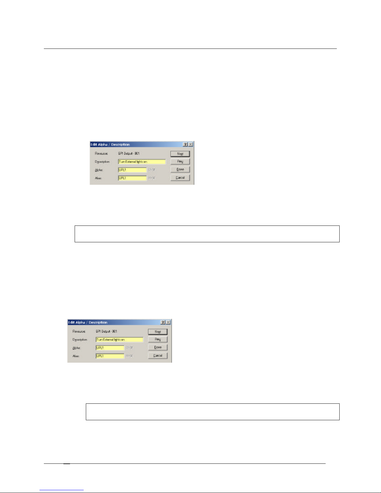
Assign GPI Output Alphas
GPI Outputs have default names, RY01, RY02, etc. You can change the defaults to more meaningful names. You
can also enter a brief description to give further information and keep track of the GPI outputs that you use.
To assign alphas to multiple special lists, do the following:
1. In AZedit, click Other Alphas.
The Other Alphas screen appears.
2. From the Other Alphas screen, select GPI Output Alphas.
The GPI Output Alphas screen appears.
3. Double-click a RY (relay).
The Edit Alpha Description screen appears.
4. In the Description field, enter a description of the GPI Output (for example, Turn External lights
on). The description field has a 24-character field limit.
5. In the Alpha field, enter a meaningful name that users would recognize for the GPI Output (for
example, UPL1). The Alpha and Alias fields have a four-character field limit.
Note: The Alias and Alpha fields populate with the same information. You can change the Alias, if
needed. For more information see, the Port Alphas screen description.
6. Click Next to assign another alpha. Otherwise, click Done.
The GPI Output default alpha is changed.
To assign a special list alpha during the special list setup, do the following:
1. In AZedit, click GPI Output.
The GPI Output screen appears.
2. Press Ctrl + F12.
The Edit Alpha Description screen appears.
3. In the Description field, enter a description of the GPI Output (for example, Turn External lights on). The
description field has a 24-character field limit.
4. In the Alpha field, enter a meaningful name that users would recognize for the GPI Output (for example,
UPL1). The Alpha and Alias fields have a four-character field limit.
Note: The Alias and Alpha fields populate with the same information. You can change the Alias, if
needed. For more information see, the Port Alphas screen description.
5. Click Done.
The GPI Output default alpha is changed.
Telex Communications
82
Page 83
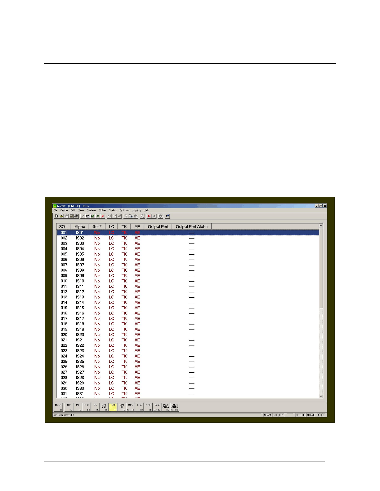
ISO
ISO is a means for a keypanel operator to isolate a particular intercom port for private communication. While the
intercom port is isolated, it can only hear audio from the keypanel operator. There is also an option called ISO Self
that cuts the keypanel operator off from the rest of the intercom system as well during the ISO operation. When the
ISO key is released, normal intercom operation is automatically restored. ISO is often used in a broadcasting
environment, and may be referred to as "Camera ISO". In this application, camera operators are often assigned to a
party line. ISO provides a means for a keypanel operator to isolate a particular camera from the party line and then
direct that camera operator without outside interference.
Each ISO can be given a name that is meaningful to keypanel operators, which is done through the Other Alpha
setup screen.
Once an ISO has been setup and named, it can be assigned to any keypanel key (provided that ISO assignment has
not been restricted or disabled in AZedit). Use the ISO Setup screen to define the intercom port that will be isolated.
Then, use keypanel setup to assign the ISO to an intercom key. After all changes have been sent to the intercom
system, the keypanel operator will be able to isolate the specified ISO output by pressing the ISO key.
Telex Communications
83
Page 84
Screen Items
Screen Item Field Type Description
ISO list column
The ISO column displays the ISO number. This number cannot be
changed. However, control over the number of ISOs available for
setup can be configured into the intercom system.
Alpha list column
The Alpha column displays the name assigned to each ISO.
Default names are ISO1, ISO2, etc. These names can be changed
to more meaningful names by selecting an ISO from the list and
pressing Ctrl+F12.
Self? list column
The Self? Column displays whether or not a keypanel operator is
isolated from the rest of the intercom system during ISO operation.
When the ISO key is released, normal intercom operation is
automatically restored.
LC list column
The LC column displays the scroll enable settings for the GPI
Output port.
LC indicates Local
TK indicates Trunk
AE indicates AZedit
For each type of scrolling, the letters will appear green if that type
of scrolling is enabled, brown (or red when selected) if that type of
scrolling is disabled.
TK list column
The TK column displays the scroll enable settings for the GPI
Output port.
LC indicates Local
TK indicates Trunk
AE indicates AZedit
For each type of scrolling, the letters will appear green if that type
of scrolling is enabled, brown (or red when selected) if that type of
scrolling is disabled.
AE list column
The AE column displays the scroll enable settings for the GPI
Output port.
LC indicates Local
TK indicates Trunk
AE indicates AZedit
For each type of scrolling, the letters will appear green if that type
of scrolling is enabled, brown (or red when selected) if that type of
scrolling is disabled.
Output Port list column
Output Port Alpha list column
The Output Port column displays the number of the port selected.
The Output Port Alpha column displays the name of the port
selected.
NOTE: To access the Edit ISO screen, double-click an ISO from the list, the Edit ISO screen
appears. For more information on the Edit ISO screen, see the AZedit Help file.
Telex Communications
84
Page 85

Right-Click Guide to the ISO screen
Built into AZedit are many different ways to get to the same information, by buttons, menus, and right -clicking. The
following is a list of menus and screens you can access by right clicking from the ISO main screen.
Right-Click Action Result
Highlight ISO > Right Click
A popup menu appears that gives you the following
options:
Info: The information contained here shows the ISO,
Description, and output.
Scroll Enable: Gives the user the ability to set scroll
enable for Local ports, Trunk ports, AZedit ports.
From the Scroll Enable menu, select Local, Trunk, or
AZedit.
From the Navigation menu, you can:
Go to ISO Alpha view
From the Changes Menu, you can
Clear all changes to this ISO /all ISOs..,.- clears all
the changes you have made up to the last Save
performed.
From the Search menu, you can:
Search for panels with this ISO assigned…
Note: You must be connected to the
Intercom for some of these menus to
work.
Right-click anywhere on the screen A popup menu appears that gives you the options to:
Undo: reverses the last action--for example, to undo a
deletion, thus restoring deleted text to a document.
Redo: will redo up to 20 consecutive changes that you
previously canceled with the Undo Button.
Go Back: lets you go back to previously viewed screens
(up to 20).
Go Forward: lets you go forward again when you have
used Go Back to look at previously viewed screens.
Search: From the Search popup menu, you can:
Search for this panel (opens the Search Status Screen)
Search for panels with this key assignment (only
available when a key assignment has been made)(opens
the Search Status Screen)
Show Grid: Opens key assignment grid.
Telex Communications
85
Page 86
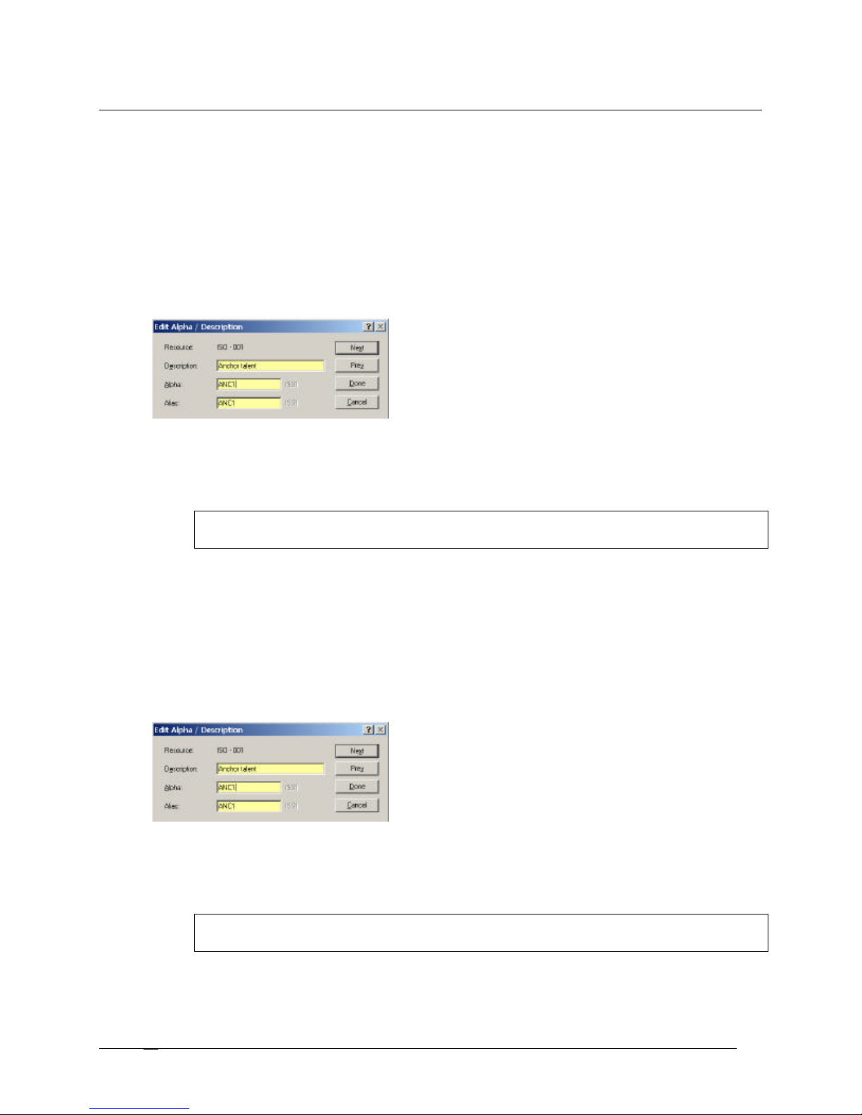
Assign ISO Alphas
ISOs have default names, IS01, IS02, etc. You can change the defaults to more meaningful names. You can also
enter a brief description to give further information and keep track of the ISOs that you use.
To assign alphas to multiple ISOs, do the following:
1. In AZedit, click Other Alphas.
The Other Alphas screen appears.
2. From the Other Alphas screen, select ISO Alphas.
The ISO Alphas screen appears.
3. Double-click an ISO.
The Edit Alpha Description screen appears.
4. In the Description field, enter a description of the ISO (for example, Anchor talent). The description field
has a 24-character field limit.
5. In the Alpha field, enter a meaningful name that users would recognize for the ISO (for example, ANC1).
The Alpha and Alias fields have a four-character field limit.
Note: The Alias and Alpha fields populate with the same information. You can change the Alias, if
needed. For more information see, the Port Alphas screen description.
6. Click Next to assign another alpha. Otherwise, click Done.
The ISO default alpha is changed.
To assign a special list alpha during the special list setup, do the following:
1. In AZedit, click ISO.
The ISO screen appears.
2. Press Ctrl + F12.
The Edit Alpha Description screen appears.
7. In the Description field, enter a description of the ISO (for example, Anchor talent). The description field
has a 24-character field limit.
8. In the Alpha field, enter a meaningful name that users would recognize for the ISO (for example, ANC1).
The Alpha and Alias fields have a four-character field limit.
Note: The Alias and Alpha fields populate with the same information. You can change the Alias, if
needed. For more information see, the Port Alphas screen description.
9. Click Done.
The ISO default alpha is changed.
Telex Communications
86
Page 87

GPI In
General Purpose Inputs and Outputs (GPIO or GPI) controls devices that use switch contact closures, DC
voltages, or similar methods. GPI Inputs can be used to activate key assignments. For example, a lighting system
can be controlled from keypanel keys or key a transmitter during transmission. GPI Inputs can also be used as inputs
to UPL statements. For example, you could program a console switch to load an entirely new intercom system setup
file.
ADAM and ADAM CS intercom systems have a General Purpose Interface (GPI) port. GPI ports have eight control
outputs (also referred to as relays) and eight control inputs. The location of the GPI port on the ADAM and ADAM CS
is as follows:
ADAM: Located on XCP-ADAM-MC Master Controller Breakout Panel, J11.
ADAM CS: Located on ADAM CS back panel, J903.
GPI Port Pin-out
All 25-pin GPI Port connectors have the same pin-out as follows:
Pin No. Function Pin No. Function
1 GPI In #1 (+5 to +18 VDC)
2 GPI In #2 (+5 to +18 VDC)
3 GPI In #3 (+5 to +18 VDC)
4 GPI In #4 (+5 to +18 VDC)
5 GPI In #5 (+5 to +18 VDC)
6 GPI In #6 (+5 to +18 VDC)
7 GPI In #7 (+5 to +18 VDC)
8 GPI In #8 (+5 to +18 VDC)
9 Common
10 Common
11 Common
12 Common
13 Common
14 GPI Out #1
15 GPI Out #2
16 GPI Out #3
17 GPI Out #4
24 Common
25 Common
18 GPI Out #5
19 GPI Out #6
20 GPI Out #7
21 GPI Out #8
22 Common
23 Common
Telex Communications
87
Page 88
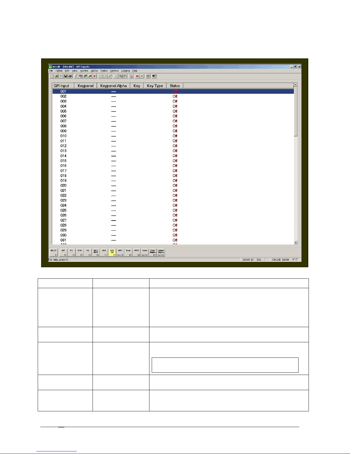
GPI Inputs for UIO-256, ADAM, and ADAM CS: Connect +5 to +18 VDC between any GPI input and common to
activate that GPI input.
Screen Items
Screen Item Field Type Description
GPI Input column display
The GPI Input column displays the number assigned to the GPI
Input. This number cannot be changed. Changing the intercom
configuration can control the number of GPI Inputs. For example,
basic system hardware has eight GPI Inputs. If no additional UIO256 frames are attached to the system, the GPI Inputs can be
limited to eight.
Keypanel column display
The Keypanel column displays the keypanel number assigned to
the GPI Input (i.e., 003).
Keypanel Alpha column display
The Keypanel Alpha column displays the name of the Keypanel
assigned to the GPI Input.
Note: To change the default name of the Keypanel Alpha,
see Port Alpha.
Key column display
The Key column displays the keypanel key assigned to the GPI
Input. This is the key used to trigger a GPI Input action.
Key Type column display
The Keypanel Type column indicates the type of key assigned to a
GPI Input. Talk or Listen is displayed in the column indicating the
key type.
Telex Communications
88
Page 89
Note: When No Key is assigned as the key type, the Key
Search for this panel
(opens the Search Status Screen)
Type column will be blank.
Status column display The Status column displays whether the GPI Input is activated,
ON; otherwise, OFF will display. This information will periodically
update.
To force an update:
1. From the View menu, select Refresh.
The display status field updates.
Or, press Ctrl+Space from the keyboard.
NOTE: To access the Edit GPI In screen, double-click a GPI In from the list, the Edit GPI In screen
appears. For more information on the Edit GPI In screen, see the AZedit Help file.
Right-Click Guide to the GPI Input Screen
Built into AZedit are many different ways to get to the same information, by buttons, menus, and right-clicking. The
following is a list of menus and screens you can access by right clicking from the GPI Input main screen.
Highlight GPI Input > Right Click
A popup menu appears that gives you the following
options:
Info: The information contained here shows the GPI
Input, Description, Keypanel, Description (keypanel), Key
Number and Type.
From the Navigation menu, you can:
Go to GPI Output view
Go to GPI Output Alpha view
Go To GPI Input Alpha view
From the Changes Menu, you can
Clear all changes to this GPI Input /all GPI Inputs..,.clears all the changes you have made up to the last
Save performed.
From the Search menu, you can:
Search for panels with this ISO assigned…
Note: You must be connected to the
Intercom for some of these menus to
work.
Right-click anywhere on the screen A popup menu appears that gives you the options to:
Undo: reverses the last action--for example, to undo a
deletion, thus restoring deleted text to a document.
Redo: will redo up to 20 consecutive changes that you
previously canceled with the Undo Button.
Go Back: lets you go back to previously viewed screens
(up to 20).
Go Forward: lets you go forward again when you have
used Go Back to look at previously viewed screens.
Search: From the Search popup menu, you can:
Telex Communications
89
Page 90

Search for panels with this key assignment (only
available when a key assignment has been made)(opens
the Search Status Screen)
Show Grid: Opens key assignment grid.
Telex Communications
90
Page 91
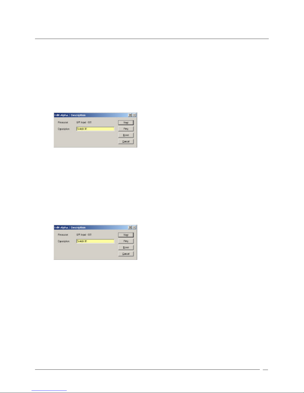
Assign GPI In Alphas
GPI Inputs can be used to activate key assignments. GPI Inputs can also be used as inputs to UPL statements.
Unlike other Alpha descriptions, GPI Inputs only allow you enter a description in the Alpha screen.
To assign alphas to multiple GPI Input descriptions, do the following:
10. In AZedit, click Other Alphas.
The Other Alphas screen appears.
11. From the Other Alphas screen, select GPI Input Descriptions.
The GPI Input Descriptions screen appears.
12. Double-click a DI (data input number).
The Edit Alpha Description screen appears.
13. In the Description field, enter a description of the GPI Input (for example, Switch #1). The description field
has a 24-character field limit.
14. Click Next to assign another alpha. Otherwise, click Done.
The GPI Input Description is entered.
To assign a GPI Input description during the special list setup, do the following:
3. In AZedit, click GPI In.
The GPI Input screen appears.
4. Press Ctrl + F12.
The Edit Alpha Description screen appears.
15. In the Description field, enter a description of the GPI Input (for example, Switch #1). The description field
has a 24-character field limit.
16. Click Done.
The GPI Input description is entered.
Telex Communications
91
Page 92

UPL
ADAM, ADAM CS, and Zeus matrices contain a feature called User Programmable Language (UPL) based on logical
statements to be implemented by the system.
UPLs give users the ability to automate or schedule certain actions to occur. For example, a building's internal
communication system via an intercom system may regulate who is contacted at different times during the day (the
receptionist from 8:30 – 4:30 and from 4:30 to Midnight all calls are sent to the security officer). A simple UPL
statement can accomplish the desired result by scheduling a Close Crosspoint on one port and Inhibit Crosspoint on
another port.
Using UPL users can construct program statements based on Boolean logic that allows the following conditions to be
met:
Output from a previous UPL statement
GPI Input
Local GPI Input
Status of GPI Output
Status of Local GPI Output
Talk Key Status
Listen Key Status
UPL Resource
UPL Operator Usage
The standard operators for input conditions (except for Current Time, Current Date, and Counter)
are:
AND both Input A and Input B must be true
OR either of Input A or Input B must be true
XOR exactly one of Input A or Input B must be true (but not both)
The following operators are only available to be used when Input A is set to "Current Date",
"Current Time", or "Counter", and in these cases Input B is then used as the value to be compared
with.
= equal to
!= not equal to
< less than
> greater than
<= less than or equal to
>= greater than or equal to
Tests are chained with other conditions through the use of AND, OR, and XOR to cause one or more of the following
actions to occur:
Crosspoint Status
Input Talking
Output Listening
Headset Transfer Switch Status
Current Date
Current Time
IFB Interrupted
Counter
Close Crosspoint
Inhibit Crosspoint
Assert GPI Output
Inhibit GPI Output
Assert GPI Output Local
Inhibit GPI Output Local
Force Talk Key Closed
Telex Communications
92
Force Talk Key Open
Dim Crosspoint Volume
Load Setup File
Force Listen Key Closed
Force Listen Key Open
Clear Counter
Page 93
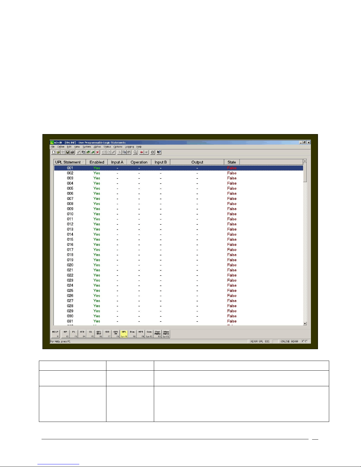
Users can construct these statements easily using the drop-down lists on the Edit UPL Statement screen. There are
1. Right
-
click t
he UPL statement you want to enable/disable.
cases where the actions to be implemented require external devices. For this purpose, RTS has included a serial
RS-232 control language called Command Line Protocol. This prot ocol allows simple ASCII communications between
the matrix and the external computer. Command Line Protocol comes standard on ADAM, ADAM CS and Zeus
matrices.
In AZedit, the number of UPL's is set in the configuration of the matrix "options" intercom configuration. For Zeus, the
UPL statement limit is set to 128; for ADAM CS, the UPL statement is 256. For a single frame ADAM, the number of
UPL statements is 256, however this is adjustable. The number can be increased, but it may degrade other dynamic
capabilities, such as the number of party lines (this is limited to the amount of memory available on the master
controller card). The available memory test is available when these matrix settings are adjusted. The Allow Intercom
Resizing in Online Mode checkbox must be selected. This is done by going to the Options menu and selecting
Preferences.
Screen Items
Screen Item Field Type Description
UPL Statement display column
Enabled display column
Telex Communications
The UPL Statement column displays the number assigned to the UPL
statement.
The Enabled column indicates if a statement is enabled to run or
disabled. If the column shows YES, this indicates enabled. If the
column shows NO, this indicated disabled.
To enable or disable the UPL statement, do the following:
93
Page 94
Input A display column
Redo
: will redo up to 20 consecutive changes that you
Operation display column
Input B display column
Output display column
State display column
NOTE: To access the Edit UPL screen, double-click a UPL Statement from the list, the Edit UPL
Statement screen appears. For more information on the Edit UPL Statement screen, see the
AZedit Help file.
A popup menu appears.
2. From the Popup menu, select Enable or Disable.
The UPL statement is enabled (YES) or disabled (NO).
The Input A column displays the input condition that must be met
before the output result becomes active (for example, GPI Input,
Counter, etc.).
The Operation column displays the operator used (AND, OR, XOR).
The Input B column displays a second input condition that must be met
before the output result becomes active. It can be thought of as linking
two conditions together. However, you can also have one or the other
of the conditions being met before the result becomes active.
The Output column displays the type of output, such as a key closure,
crosspoint force or inhibit, etc.
The State column indicates the current state of the UPL statement.
True indicates the output condition is true when the condition (s) for A
or A and B is met.
False indicates the output condition wasn't met.
Right-Click Guide to the UPL Screen
Built into AZedit are many different ways to get to the same information, by buttons, menus, and right-clicking. The
following is a list of menus and screens you can access by right clicking from the UPL main screen.
Highlight UPL statement > Right Click
Right-click anywhere on the screen A popup menu appears that gives you the options to:
A popup menu appears that gives you the following
options:
Info: The information contained here shows the UPL
Statement, any Comments, and the State of the
statement.
From the Navigation menu, you can:
Go to UPL Resources view
Go to UPL Resource Alpha view
From the Changes Menu, you can
Clear all changes to this UPL /all UPLs..,.- clears all
the changes you have made up to the last Save
performed.
From the Search menu, you can:
Search for panels with this ISO assigned…
Note: You must be connected to the
Intercom for some of these menus to
work.
Undo: reverses the last action--for example, to undo a
deletion, thus restoring deleted text to a document.
Telex Communications
94
Page 95
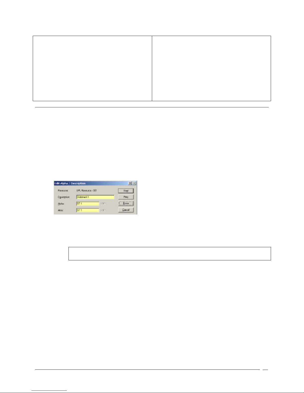
previously canceled with the Undo Button.
Go Back: lets you go back to previously viewed screens
(up to 20).
Go Forward: lets you go forward again when you have
used Go Back to look at previously viewed screens.
Search: From the Search popup menu, you can:
Search for this panel (opens the Search Status Screen)
Search for panels with this key assignment (only
available when a key assignment has been made)(opens
the Search Status Screen)
Show Grid: Opens key assignment grid.
Assign UPL Alphas
UPL's have default names, 001, 002, etc. You can change the defaults to more meaningful names. You can also
enter a brief description to give further information and keep track of the UPL's that you use.
To assign alphas to multiple UPL's, do the following:
17. In AZedit, click Other Alphas.
The Other Alphas screen appears.
18. From the Other Alphas screen, select ISO Alphas.
The ISO Alphas screen appears.
19. Double-click a UR (UPL resource).
The Edit Alpha Description screen appears.
20. In the Description field, enter a description of the UR (for example, Statement 1). The description field has
a 24-character field limit.
21. In the Alpha field, enter a meaningful name that users would recognize for the UR (for example, ST 1). The
Alpha and Alias fields have a four-character field limit.
Note: The Alias and Alpha fields populate with the same information. You can change the Alias, if
needed. For more information see, the Port Alphas screen description.
22. Click Next to assign another alpha. Otherwise, click Done.
The UR default alpha is changed.
Telex Communications
95
Page 96
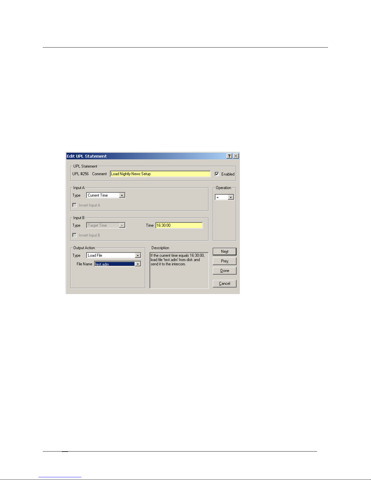
UPL Statement Examples
Timed Setup File Example
This example shows how a UPL statement works. Let's say you have broadcast news show every day at 5pm and
you want the intercom system to automatically load and entire intercom system setup file every day at 4:30pm for the
broadcast. Using UPL statements you could have the setup file load automatically every day.
To write the UPL statement, do the following:
1. In AZedit, open the setup file that will be running BEFORE the file you want to load at 4:30.
2. Click UPL.
The User Programmable Logic Statements screen appears.
3. Double-click a UPL Statement .
The Edit UPL Statement screen appears.
4. In the Comment field, enter a description of the UPL statement you are creating (for example, Load Nightly
News Setup). This serves as a reminder of what the UPL statement does.
5. Verify the Enabled checkbox is selected.
6. From the Input A Type drop-down list, select Current Time.
This is part of the input condition that has to be met before the UPL statement initiate and load the setup file.
7. From the Operation drop-down list, select = (equal).
Telex Communications
96
Page 97
Operator Usage
The standard operators for input conditions (except for Current Time, Current Date, and Counter)
are:
AND both Input A and Input B must be true
OR either of Input A or Input B must be true
XOR exactly one of Input A or Input B must be true (but not both)
The following operators are only available to be used when Input A is set to "Current Date",
"Current Time", or "Counter", and in these cases Input B is then used as the value to be compared
with.
= equal to
!= not equal to
< less than
> greater than
<= less than or equal to
>= greater than or equal to
8. In the Time field, enter the time. The time is based on a 24-hour clock. For example, 4:30pm is thought of as
16:30:00.
9. From the Output Action Type drop-down list, select Load File.
A File Name drop-down list appears.
Note: All setup files are kept in the Setup file located in the TELEX folder on your C:\ drive.
10. From the File Name drop down list, select the file that will load (for example, test.adm).
Note: There is a description box near the bottom right that provides an English text description of
what the UPL statement you create will do. This allows you to play around with inputs, outputs, and
operators to see what the effect of each is.
The UPL statement is now created. Once these changes are sent to the intercom system, the setup file prepared
will automatically load at the specified time.
IMPORTANT: Activate SERVER mode. AZedit must be operating in SERVER mode for the intercom system
to be able to load the files. For more information on SERVER mode, see Connecting and Disconnecting.
Telex Communications
97
Page 98
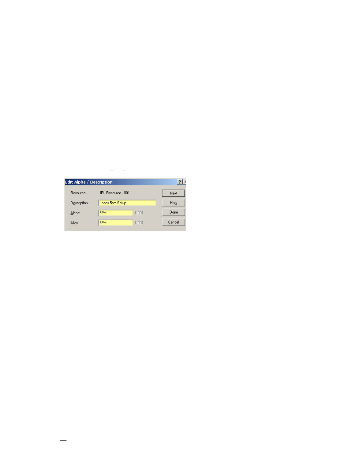
Use a UPL Resource Key to Load a Setup File
This example shows how you can set up a keypanel key that will load an intercom system setup file when the key is
pressed. As an example, suppose that you want to set up a key on a keypanel that will load an intercom setup file for
a broadcast program at 5pm. Then, at 4:55, an operator can press the key on the keypanel thereby loading the setup
file for the broadcast.
To set up this process, a UPL Resource needs to be named, the UPL resource needs to be assigned to a key on the
keypanel, and then, a UPL statement needs to be created to load the setup file.
To use a UPL resource key to load a setup file, do the following:
1. In AZedit, open the setup file that will be running BEFORE the file you want to load just before 5pm.
2. Click Other Alphas.
The Other Alphas screen appears.
3. On the Other Alphas screen, select UPL Resource Alphas.
The UPL Resource Alphas screen appears.
4. Double-click a UR (UPL Resource) from the UR list.
The Edit Alpha Description screen appears.
5. In the Description field, enter a description of the UPL Resource (for example, Loads 5pm Setup). This
should be something to remind you what the UPL resource is being used for.
6. In the Alpha field, enter the name you want displayed as the UPL Resource (for example, 5PM). The Alpha
appears in the alphanumeric display of a keypanel.
7. Click Done.
The Edit Alpha Description screen closes and the UPL Resource is renamed.
8. In the bottom tool bar, click KP (or press F2).
The Keypanels / Ports main screen appears.
9. In the Port field, enter the port number with which you want to work. (You can also select an Alpha from the
Alpha drop-down box.
10. Right-click in a talk key combo box.
A popup menu appears.
Telex Communications
98
Page 99
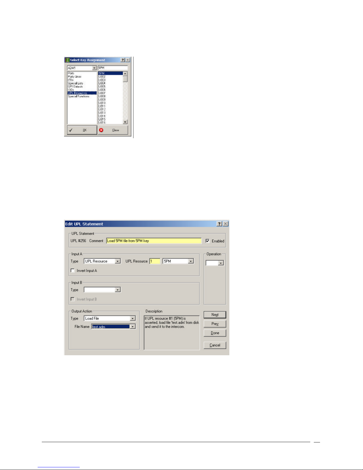
11. Select Change Assignment.
The Select Key Assignment screen appears.
12. In the key type list, select the type of intercom key you want to assign (for example, UPL Resource).
13. In the name list (on the right), select a name (alpha) for the key (for example, 5PM).
14. Click OK.
The Selected Key Assignment screen closes and the selected name appears in the key assignment combo
box on the Keypanels / Ports screen.
15. Click UPL.
The User Programmable Logic Statements screen appears.
16. Double-click a UPL Statement.
The Edit UPL Statement screen appears.
17. In the Comment field, enter a description of the UPL statement you are creating (for example, Load 5PM
file from 5PM key). This serves as a reminder of what the UPL statement does.
18. Verify the Enabled checkbox is selected.
19. From the Input A Type drop -down list, select UPL Resource.
This is part of the input condition that has to be met before the UPL statement initiates and loads the setup
file.
Telex Communications
99
Page 100
20. From the Output Action Type drop-down list, select Load File.
A File Name drop-down list appears.
Note: All setup files are kept in the Setup file located in the TELEX folder on your C:\ drive.
21. From the File Name drop down list, select the file that will load (for example, test.adm).
Note: There is a description box near the bottom right that provides an English text description of
what the UPL statement you create will do. This allows you to play around with inputs, outputs, and
operators to see what the effect of each is.
The UPL statement is now created. Once these changes are sent to the intercom system, the setup file prepared
will load when the keypanel key is pressed.
IMPORTANT: Activate SERVER mode. AZedit must be operating in SERVER mode for the intercom system
to be able to load the files. For more information on SERVER mode, see Connecting and Disconnecting.
Telex Communications
100
 Loading...