

Telex SS-2002, SS-2002 RM, Audiocom SS-1002, Audiocom SS-2002, Audiocom SS-2002 RM Technical Manual
Model SS-1002
Single-Channel Intercom Speaker Station
Models SS-2002
Two-Channel Intercom Speaker Station
Model SS-2002 RM
Two-Channel Rack Mount Intercom Speaker Station
Technical Manual
9350-7741-000 Rev F 11/2010
PROPRIETARY NOTICE
This package should include the following:
The product information and design disclosed herein were originated by
and are the property of Bosch Security Systems, Inc. Bosch reserves all
patent, proprietary design, manufacturing, reproduction, use and sales
rights thereto, and to any article disclosed therein, except to the extent
rights are expressly granted to others.
COPYRIGHT NOTICE
Copyright 2010 by Bosch Security Systems, Inc. All rights reserved.
Reproduction, in whole or in part, without prior written permission from
Bosch is prohibited.
WARRANTY AND SERVICE INFORMATION
For warranty and service information, refer to the appropriate web site
below:
RTSwww.rtsintercoms.com/warranty
RTSTWwww.rtstw.com/warranty
AudioComwww.telexaudiocom.com/warranty
RadioComwww.telexradiocom.com/warranty
Headsetswww.intercomheadsets.com/warranty
CUSTOMER SUPPORT
QTY DESCRIPTION PART NO.
1 SS-1002, 1 channel front plate assemblyOR9010-7741-000
1 SS-2002, 2 channel front plate assembly 9010-7741-001
1 User Manual 9350-7741-000
4 Screw, Flat Head, 6-32 x 5/16” 51847-122
One of the following, depending on what was ordered:
1 P-box, 1-channel 9010-7627-007
1 S-box, w/handle, 1-channel 9010-7627-008
1 P-box, 2-channel 9010-7627-009
1 S-box, w/handle, 2-channel 9010-7627-010
1 U-box 9010-7627-004
1 S-box, w/out handle, 1-channel 9010-7627-011
1 S-box, w/out handle, 2-channel 9010-7627-012
1 Warranty Card 38110-390
2 End Caps 9310-7620-001
1 Statement of Conformity 38109-675
SS-2002RM
1 SS-2002RM Final Assembly 9010-7742-000
4 Foot, bumper, black 56471-001
1 User Instructions 9350-7741-000
1 Statement of Conformity 38109-675
1 Warranty 38110-390
Technical questions should be directed to:
Customer Service Department
Bosch Security Systems, Inc.
12000 Portland Avenue South
Burnsville, MN 55337 USA
Telephone: 877-863-4169
Fax: 800-323-0498
Info@rtsintercoms.com
Technical Questions EMEA
Bosch Security Systems Technical Support EMEA
http://www.rtsintercoms.com/contact_main.php
FCC Statement
This equipment uses, and can radiate radio frequency energy that may
cause interference to radio communications if not installed in
accordance with this manual. The equipment has been tested found to
comply with the limits of a Class A computing device pursuant to
Subpart J Part 15 of FCC Rules which are designed to provide
reasonable protection against such interference when operated in a
commercial environment. Operation of this equipment in a residential
area may cause interference which the user (at his own expense) will be
required to correct.
This product meets Electromagnetic Compatibility
Directive 89/336/EEC
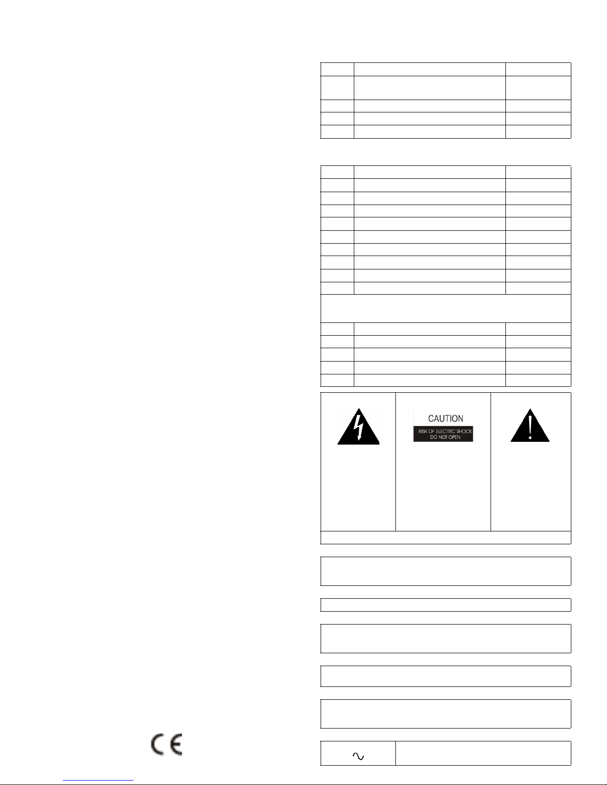
THE LIGHTNING
FLASH AND
ARROWHEAD
WITHIN THE
TRIANGLE IS A
WARNING SIGN
ALERTING YOU OF
“DANGEROUS
VOLTAGE” INSIDE
THE PRODUCT.
SEE MARKING ON BOTTOM/BACK OF PRODUCT
WARNING: APPARATUS SHALL NOT BE EXPOSED TO DRIPPING OR
SPLASHING AND NO OBJECTS FILLED WITH LIQUIDS, SUCH AS VASES,
SHALL BE PLACED ON THE APPARATUS.
WARNING: THE MAIN POWER PLUG MUST REMAIN READILY OPERABLE
CAUTION: TO REDUCE THE RISK OF ELECTRIC SHOCK, GROUNDING OF
THE CENTER PIN OF THIS PLUG MUST BE
MAINTAINED.
WARNING: TO REDUCE THE RISK OF FIRE OR ELECTRIC SHOCK, DO NOT
EXPOSE THIS APPRATUS TO RAIN OR MOISTURE.
WARNING: TO PREVENT INJURY, THIS APPARATUS MUST BE SECURELY
ATTACHED TO THE FLOOR/WALL/RACK IN
ACCORDANCE WITH THE INSTALLATION INSTRUCTIONS.
CAUTION: TO REDUCE
THE RISK OF ELECTRIC
SHOCK, DO NOT REMOVE
COVER. NO USERSERVICABLE PARTS
INSIDE. REFER
SERVICING TO
QUALIFIED SERVICE
PERSONNEL.
THE EXCLAMATION
POINT WITHIN THE
TRIANGLE IS A
WARNING SIGN
ALERTING YOU OF
IMPORTANT
INSTRUCTIONS
ACCOMPANYING
THE PRODUCT
This product is AC only.

Important Safety Instructions
1. Read these instructions.
2. Keep these instructions.
3. Heed all warnings.
4. Follow all instructions.
5. Do not use this apparatus near water.
6. Clean only with dry cloth.
7. Do not block any ventilation openings. Install in accordance with the
manufacturer’s instructions.
8. Do not install near any heat sources such as radiators, heat registers, stoves, or
other apparatus (including amplifiers) that produce heat.
9. Do not defeat the safety purpose of the polarized or grounding-type plug. A
polarized plug has two blades with one wider than the other. A grounding type
plug has two blades and a third grounding prong. The wide blade or the third
prong are provided for your safety. If the provided plug does not fit into your
outlet, consult an electrician for replacement of the obsolete outlet.
10.Protect the power cord from being walked on or pinched particularly at plugs,
convenience receptacles, and the point where they exit from the apparatus.
11.Only use attachments/accessories specified by the manufacturer.
12.Use only with the cart, stand, tripod, bracket, or table specified by the
manufacturer, or sold with the apparatus. When a cart is used, use caution when
moving the cart/apparatus combination to avoid injury from tip-over.
13.Unplug this apparatus during lightning storms or when unused for long periods
of time.
14.Refer all servicing to qualified service personnel. Servicing is required when the
apparatus has been damaged in any way, such as power-supply cord or plug is
damaged, liquid has been spilled or objects have fallen into the apparatus, the
apparatus has been exposed to rain or moisture, does not operate normally, or
has been dropped.


Table
of
Contents
INTRODUCTION ....................................................................................................................................... 3
Introduction ...............................................................................................................................................................3
Description ................................................................................................................................................................3
Features ......................................................................................................................................................................4
INSTALLATION ........................................................................................................................................ 7
Configuration Pre-check ............................................................................................................................................7
DIP Switches .............................................................................................................................................................7
Mic Kill Receive ........................................................................................................................................................8
Call Signal Compatibility ..........................................................................................................................................8
Incoming Call Beep ...................................................................................................................................................8
Microphone Type ......................................................................................................................................................8
Speaker Beep for Incoming Call ...............................................................................................................................9
Balanced/Unbalanced Switch ....................................................................................................................................9
Sidetone Trimmers ....................................................................................................................................................9
Headset Connector Notes ..........................................................................................................................................9
Panel Mic Connector Notes .......................................................................................................................................9
Intercom Channel Connections ...............................................................................................................................10
Description of Phantom-Powered Connection ........................................................................................................10
Description of Locally Powered Connection ..........................................................................................................11
All Locally Powered Intercom Stations (Dry Lines) ...............................................................................................12
OPERATION AND SPECIFICATIONS ................................................................................................ 15
Power Up .................................................................................................................................................................15
Sidetone Adjustment ...............................................................................................................................................15
Channel Select (SS-2002 & SS-2002RM Only) .....................................................................................................16
Headset/Headphone/Speaker/Microphone Selection ..............................................................................................16
Receiving Calls ........................................................................................................................................................16
Calling an Intercom Channel ...................................................................................................................................17
Specifications ..........................................................................................................................................................18
Dimensions ..............................................................................................................................................................19
SS1002/2002 SUPPLEMENTAL INFORMATION ............................................................................... 21
Installing the Box to the Faceplate ..........................................................................................................................21
GENERAL INSTRUCTIONS .......................................................................................................................................................21
Notes ........................................................................................................................................................................23


CHAPTER 1
Introduction
Introduction
Thank you for purchasing the Audiocom SS-1002/2002/2002RM Intercom Speaker Station. We hope the many design features
of this product satisfies your intercommunication requirements for many years to come. To get the most out of you new
intercom stations, take a few moments to look through this manual before using the Intercom Speaker Stations for the first
time.
Description
The Intercom Speaker Stations may be used with a headset, or with the built-in speaker and panel microphone or an optional
gooseneck microphone. Another option is to use headphones and either the built-in panel microphone or an optional
gooseneck microphone. As an alternative to a headset, a telephone-style handset may also be used.
The SS-1002 is a single-channel station; the SS-2002 & SS-2002RM provide switch selectable access to either of two (2)
intercom channels. Both the SS-1002 and the SS-2002 come in three (3) versions to suit a variety of applications.
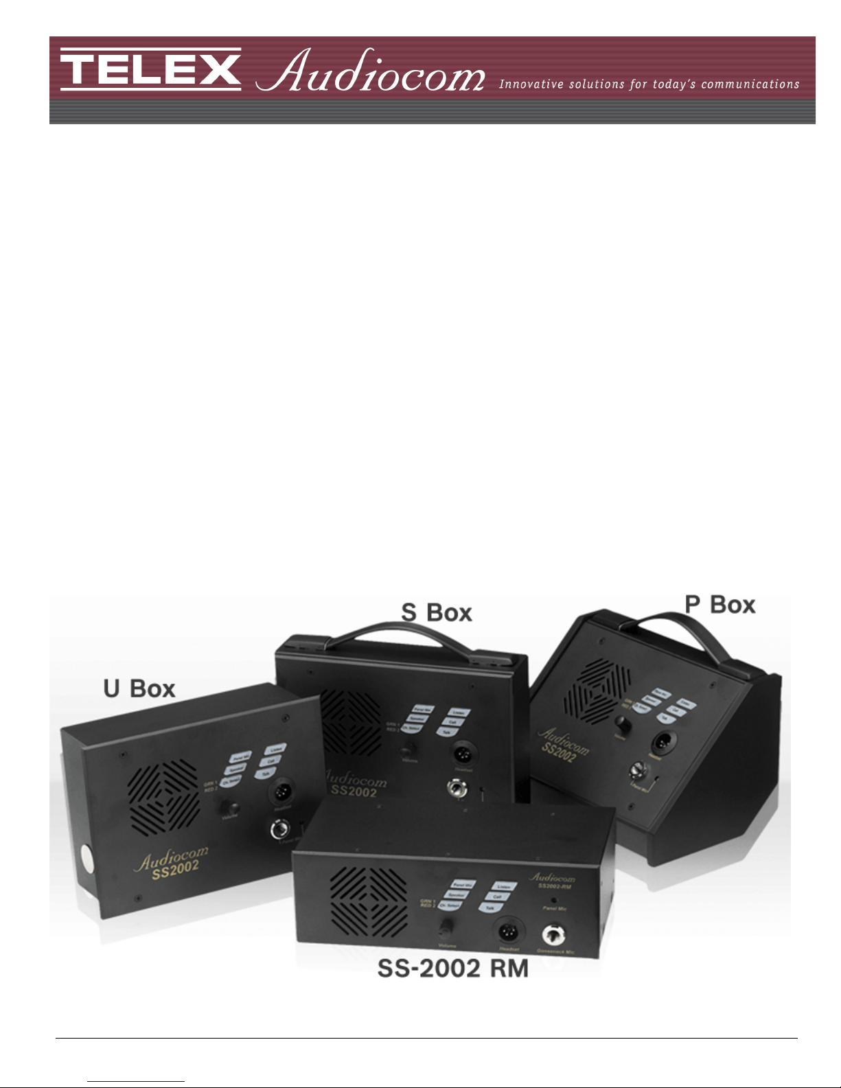
S Box - The S box is a portable version. It has a carrying handle and dual loop-through intercom connectors which
permit stations to be quickly interconnected using pre-fabricated cables.
P Box - The P box is stationary version. It also has dual loop-through connectors for quick interconnection, but the
case is designed for desktop or console-mount applications.
U Box - The U box is designed for permanent, in-the-wall mounting. It uses push-type wire terminals for connection
to the intercom system.
NOTE: In addition, the SS-2002RM can be used on a desktop or mounted in a standard 19” equipment rack (using the
optional RM-14 Rack Mount Kit).
3

Features
Use Figure 1 and Figure 2 to locate the features described below.
1. Channel and Power Connections -
2. Configuration DIP Switches -
3. Panel Mic Key -
4. Speaker Key -
5. Channel Select Key
(SS-2002 & SS-2002RM only) -
The U box uses quick release terminals to connect to audio and power wires.
For the S box and P box versions, the terminal connections are connected to
the dual, loop-through XLR connectors on the side of the box. These permit
several stations to be connected in a string, or daisy-chain, using prefabricated intercom cables.
Controls the following features:
Call Beep- In addition to a flashing call key indication for incoming calls,
an incoming call beep tone can also be used.
Headset Microphone Type Selection- Either a balanced or unbalanced
dynamic microphone can be selected.
DC call enable- This may be turned on to use the intercom station with
intercom systems that use DC call signaling.
Selects the Panel Mic/Built-in Mic connector (11) in the on position, the
headset connector (10) in the off position.
Selects the built-in speaker in the on position, the headset connector (10) in
the off position.
Selects intercom channel 1 or 2. The key lights green for channel 1 and red for
channel 2
6. Vol um e C on tr o l -
7. Intercom Listen Key -
8. Call Key -
9. Intercom Talk Key -
10. Dynamic-Mic Headset Connector -
11. Panel Mic Connector -
12. Built-in Panel Microphone -
Adjusts intercom listen volume to headphones or speaker.
Both momentary (also known as push-to-listen) and latching (also known as
hands-free-listen) functions are possible.
Use to send call signals on the intercom channel. Flashes for incoming calls.
Only the momentary (push-to-talk) function is possible. All models are
equipped with a mic kill receive circuit, which allows an operator at a remote
master station (such as the US-2000A) to turn off the talk key on all stations
along the intercom line.
4-pin male XLR connector accepts headsets with monaural headphones and
either a balanced or unbalanced dynamic microphone. Also accepts a
telephone style handset. It can be used with headphones when a panel mic is
connected. A handheld microphone along with the internal speaker can also
be used.
Accepts an electret gooseneck microphone such as the Telex MCP-90.
Active when the Panel Mic key is pressed and a gooseneck microphone is not
inserted in the Panel Mic connector.
4
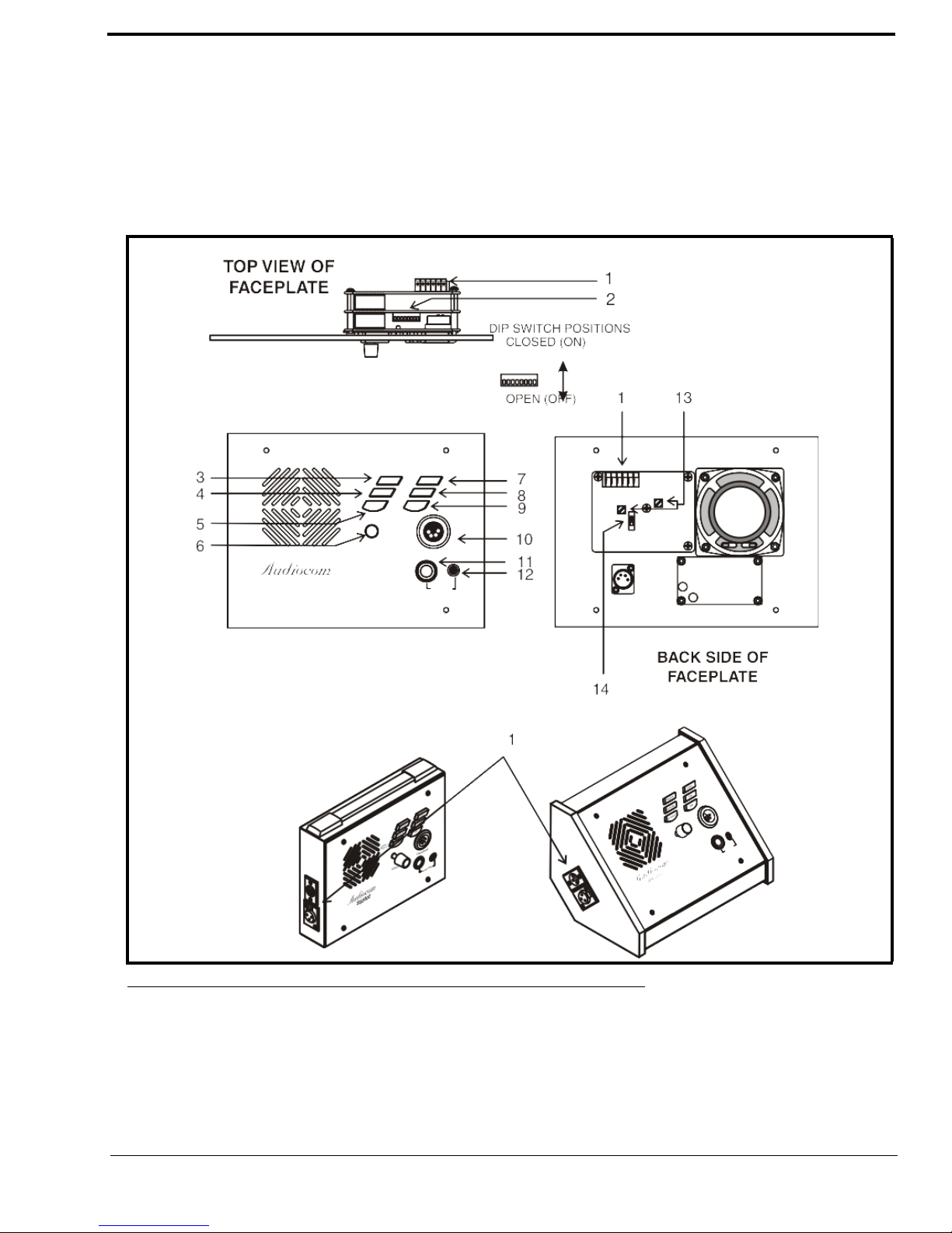
13. Sidetone Trimmers -
The sidetone trimmers adjust the level of the user’s own voice in the
headphones when using full-cushion headphones. When using the speaker or
open-ear style headphones, the sidetone trimmers are adjusted to eliminate the
user’s voice from the headphones or speaker. This helps to prevent feedback.
14. Balanced/Unbalanced Selector
Switch -
This switch sets the intercom station for compatibility with either Audiocom
(balanced) or Clear-Com (unbalanced) intercom systems.
FIGURE 1. SS-1002/2002 Features
5
 Loading...