

Telex Audiocom IFB-1000 Operating Instructions Manual
Te l e x
®
Operating Instructions
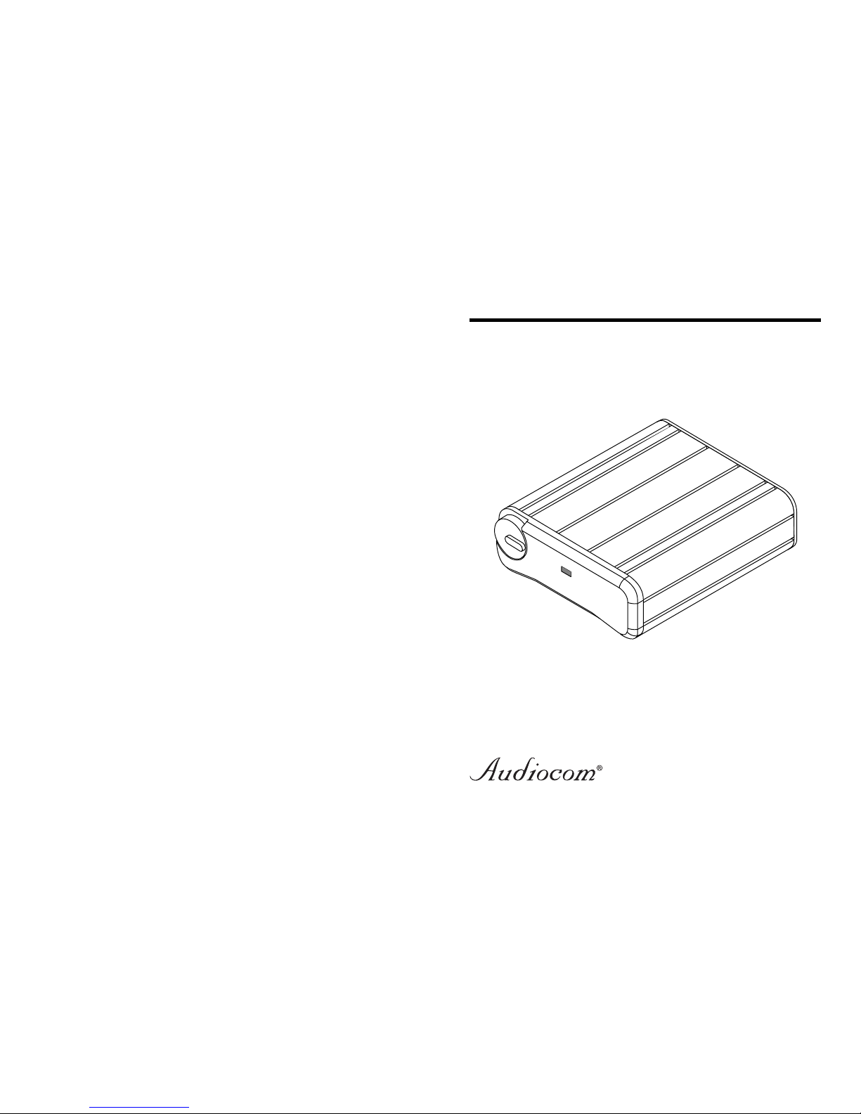
IFB-1000
Belt Pack
Intercom System
FACTORY SERVICE
All equipment returned for repair must be accompanied by documentation
stating your return address, telephone number and proof of date of
purchase, along with a description of the problem.
Return equipment to:
Factory Service Department
Telex Communications, Incorporated
West 1st Street
Blue Earth, MN 56013 U.S.A.
Warranty Repairs - If in warranty, no charge will be made for the repairs.
Equipment being returned for warranty repair must be sent prepaid and
will be returned prepaid.
Non-Warranty Repairs - Equipment that is not under warranty must be
sent prepaid. If requested, an estimate of repair costs will be issued prior
to service. Once your approval for repair, and repair of equipment is
completed, the equipment will be returned on a collect basis. Collect
charges may be avoided by sending a signed check for payment in full
along with your signed estimate approval form (the estimate includes the
shipping charge.)
CUSTOMER SUPPORT
Technical questions should be directed to:
Customer Service Department
Telex Communications, Inc.
12000 Portland Avenue South
Burnsville, MN 55337 U.S.A.
Telephone: (952) 884-4051
Fax: (800) 323-0498
9350-7477-000 Rev. B 10/2000
GENERAL
The Audiocom® IFB-1000 is a one-channel listen only IFB belt pack.
OPERATION
SYSTEM POWER
The IFB-1000 belt pack receives power externally, via the intercom
channel.
IFB-1000 SETUP
The channel termination is set for balanced operation, which is compatible with other Audiocom equipment.
The headset/earset jack is set for 150 ohm operation.
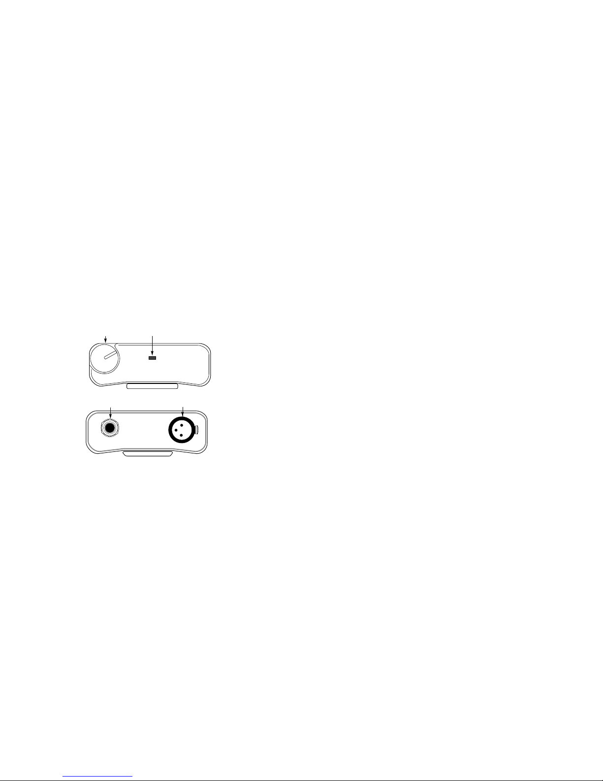
EXTERNAL CONNECTIONS & CONTROLS
1 2
4
HEADSET
3
IFB-1000
1. Volume Control.
Use this control to adjust the headset/earset listen level.
2. On Indicator
This LED glows green when the belt pack is connected to an intercom
channel that is functioning.
3. Headset Connector
This connector accepts a wide-response earset, such as the Telex
EMV-2 (catalog number 60194-001), with a 1/4” monaural phone plug.
4. Intercom Channel Connectors
The IFB-1000 intercom channel is connected via a 3-pim female
connector. The IFB-1000 is powered from the intercom system power
supply and will turn on with the intercom system.
CONNECTOR PIN CONFIGURATIONS
HEADSET CONNECTOR
Type: 1/4” Monaural Plug
Sleeve Headset audio low
Tip Headset audio high
INTERCOM CHANNEL CONNECTORS
Type: XLR-3F
Pin 1 Common
Pin 2 Intercom audio and +24 VDC input
Pin 3 Intercom audio and +24 VDC input
SPECIFICATIONS
GENERAL:
Channel Supplied Power Requirements:
+24 VDC nominal (standard Audiocom line), 50 to 80 mA
Environmental Requirements:
Storage: -20°C to 80°C; 0% to 95% humidity, non-condensing
Operating: 0°C to 50°C; 0% to 95 % humidity, non-condensing
Dimensions:
3.25” (82.6 mm) H x 3.5” (88.9 mm) W x 1.8” (45.7 mm) D
Weight:
1.0 pounds (0.45 kg)
INTERFACE REQUIREMENTS:
Earset:
150 to 600 ohm headphones
Balanced Intercom Channel Level & Impedance:
1 Vrms nominal; 300 ohms ±5%
Noise Contribution:
Less than -60 dB on the line.
HEADPHONE AMPLIFIER:
Voltage Gain:
27 ±3 dB from the line
Maximum Output:
60 mW into 150 ohms
Frequency Response:
200 Hz to 8 kHz +1/-3 dB
 Loading...