

Page 1
®
Te l e x
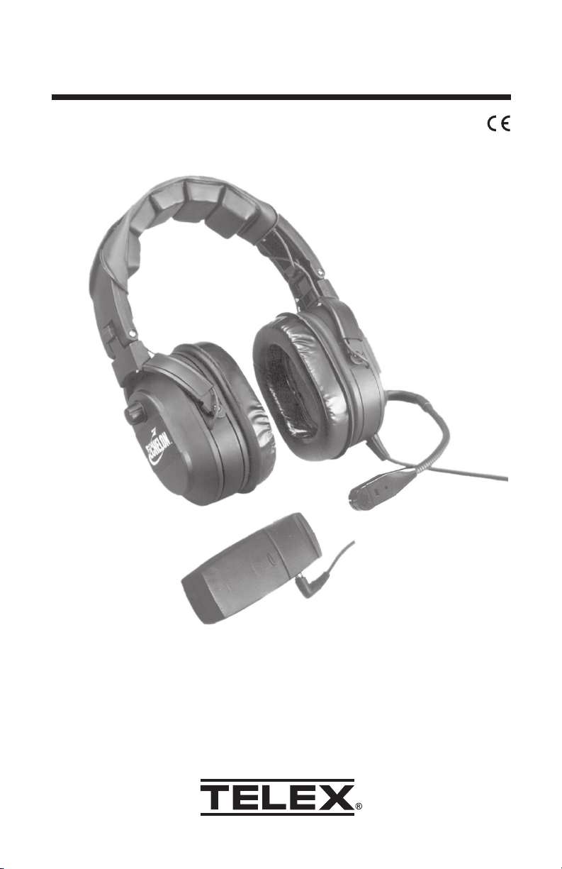
Operating Instructions
Echelon
ANRTM 150 Headset
Page 2
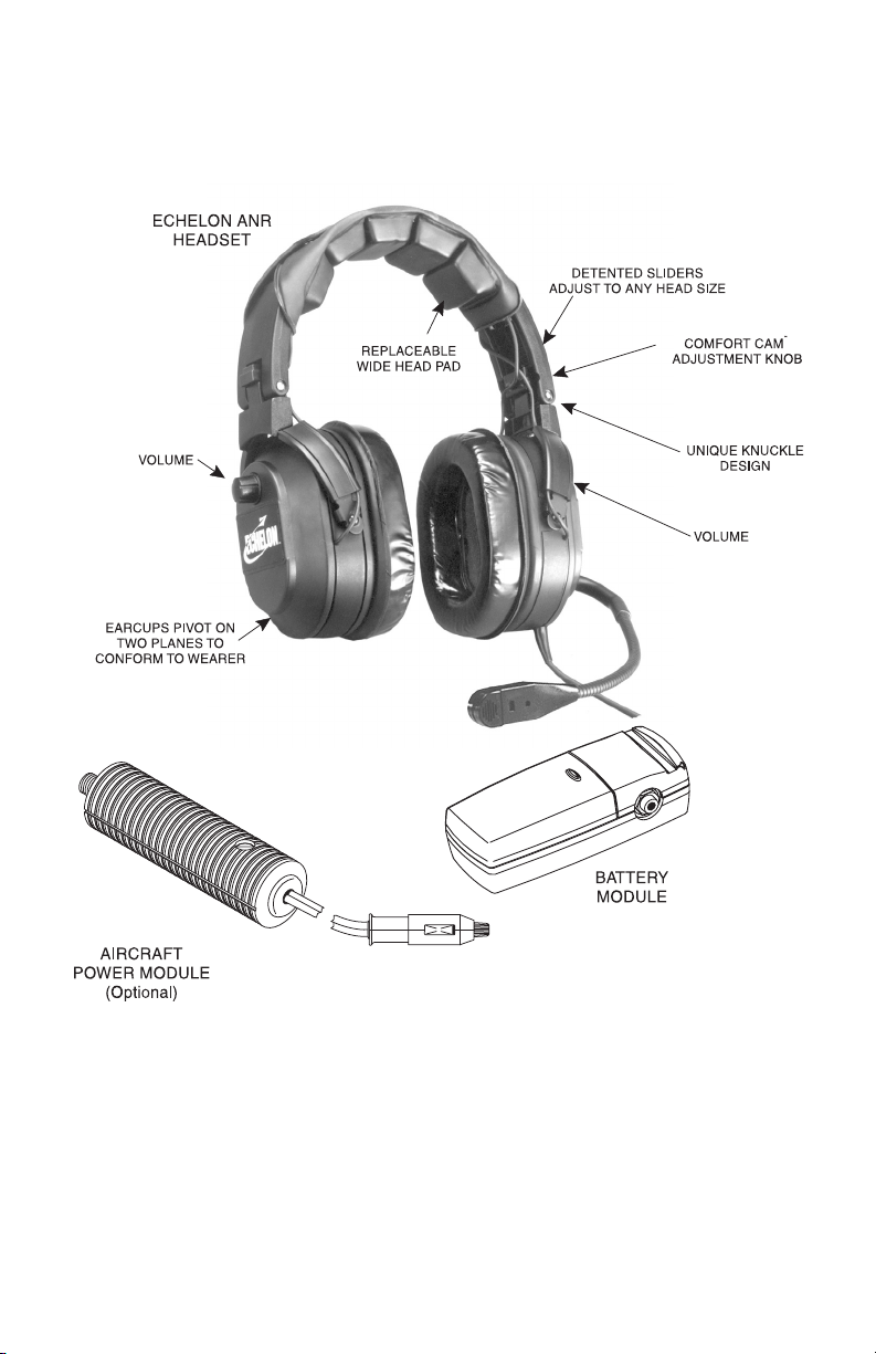
Figure 1
Note: See page 7 for available replacement parts.
Page 3

General Description
The Echelon ANR 150 is a medium-weight aircraft communications
headset. It features electronic noise reduction circuitry for improved
reduction of aircraft motor and wind noise. The Echelon ANR 150 also
features extended response receivers for improved sound reproduction
from the aircraft radio and entertainment system.
The Echelon ANR 150 noise reduction system may be powered from
either a battery module or an aircraft power module. The battery module
is designed for portable applications and uses one 9 volt battery.
Operating time with alkaline batteries is 40 hours minimum. The aircraft
power module is designed for permanent installation and provides power
to the headset from the aircraft electrical system. The aircraft power
module works with negative ground electrical systems.
The Echelon ANR 150 headset features a stereo headphone plug and a
stereo/mono select switch. The Echelon ANR 150 can be plugged directly
into an aircraft radio for standard monaural communications or into an
intercom system wired for stereo entertainment.
FAA TSO C57a and C58a approved.
Design Features (See Figure 1)
Fit and Comfort
A unique headband design distributes ear cushion pressure evenly over
the entire ear with no pressure points, unlike conventional designs which
apply more pressure on the bottom of the ear than on the top. An added
advantage of this design is that the headset folds into an extremely
compact shape for storage. A clamp adjustment on each knuckle adjusts
to provide greater noise reduction or greater comfort. The earcups pivot
on two planes to conform to any wearer. Detented sliders adjust the
headband for best fit on any head size. A large head pad evenly
distributes the headset weight on the head with no pressure points.
Comfortable foam-filled ear cushions are standard.
Boom Microphone
A flexible gooseneck boom permits precise microphone placement. The
boom rotates overhead to use the microphone on either side of the head.
The plug-in microphone cartridge features a noise-canceling electret element. The cartridge unsnaps for easy replacement. A built-in microphone
amplifier (electret version) operates on current supplied by the aircraft radio
via the microphone jack.
Cordage and Plugs
The microphone cordage is protected inside the boom arm. Shielded wire
throughout the headset protects against RFI and EMI. Strain-reliefs on all
cords provide maximum durability. A separate plug connects the headset
to either a battery module or an aircraft power module. The headset also
has separate microphone and receiver plugs. The receiver plug is a stereo
type, but a selector switch on the cord permits monaural operation.
Page 1
Page 4
Microphone Bias Voltage Requirements
The boom microphone requires a bias voltage of 8-16 VDC through 300 to
1000 ohms. If you are uncertain whether your avionics equipment meets
this requirement, consult the avionics equipment manufacturer.
Optional Aircraft Power Supply Module
The power supply module is designed for use in negative ground electrical
systems only. Do not attempt to use with positive-ground electrical systems.
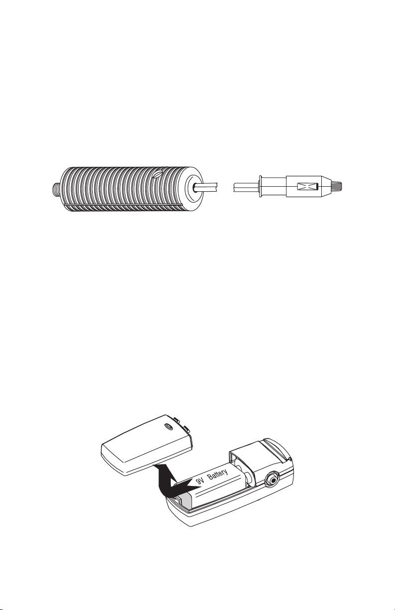
Installing a Battery in the Optional Battery
Module
The battery module requires one 9 volt battery. Alkaline batteries are recommended for best performance. Do not use nickel-cadmium rechargeable batteries or lithium batteries.
1. Slide the battery door over in the direction of the arrow, then up to
remove the battery door.
2. Snap the battery onto the battery connector and place the battery into
the case.
3. Slide the battery door back into place.
Page 2
Page 5

Headset Operation
1. Connect the headset as shown in Figure 2. Set the MONO/STEREO
headphone switch to match the type of sound system in your aircraft.
Figure 2. Headset Connection
2. Rotate the entire boom overhead to wear the microphone on either
the right or left side of the head.
3. For best noise cancellation, position the microphone as close to the
mouth as possible and speak in a normal voice (Figure 4).
4. To activate noise reduction, plug the headset into the battery or
power module. To turn off noise reduction, unplug the headset from
the battery or power module.
5. With the headband resting securely on the top of the head, check
that the ear cups are centered over the ears. Reposition them if necessary by moving the headband sliders out or in. Proper performance
depends on proper fit of the headset.
6. Headband Pressure Adjustments:
There are three pressure settings. Increasing the pressure will im-
prove the seal between the earcup and the head for greater noise
reduction. To change the pressure setting, remove the headset and
fold the earcup inward as shown in Figure 3, then rotate the adjustment knob to the desired setting. Repeat for both earcups. Both sides
of the headband should be set to the same pressure setting to keep
the headband properly centered on the head.
Page 3
Page 6
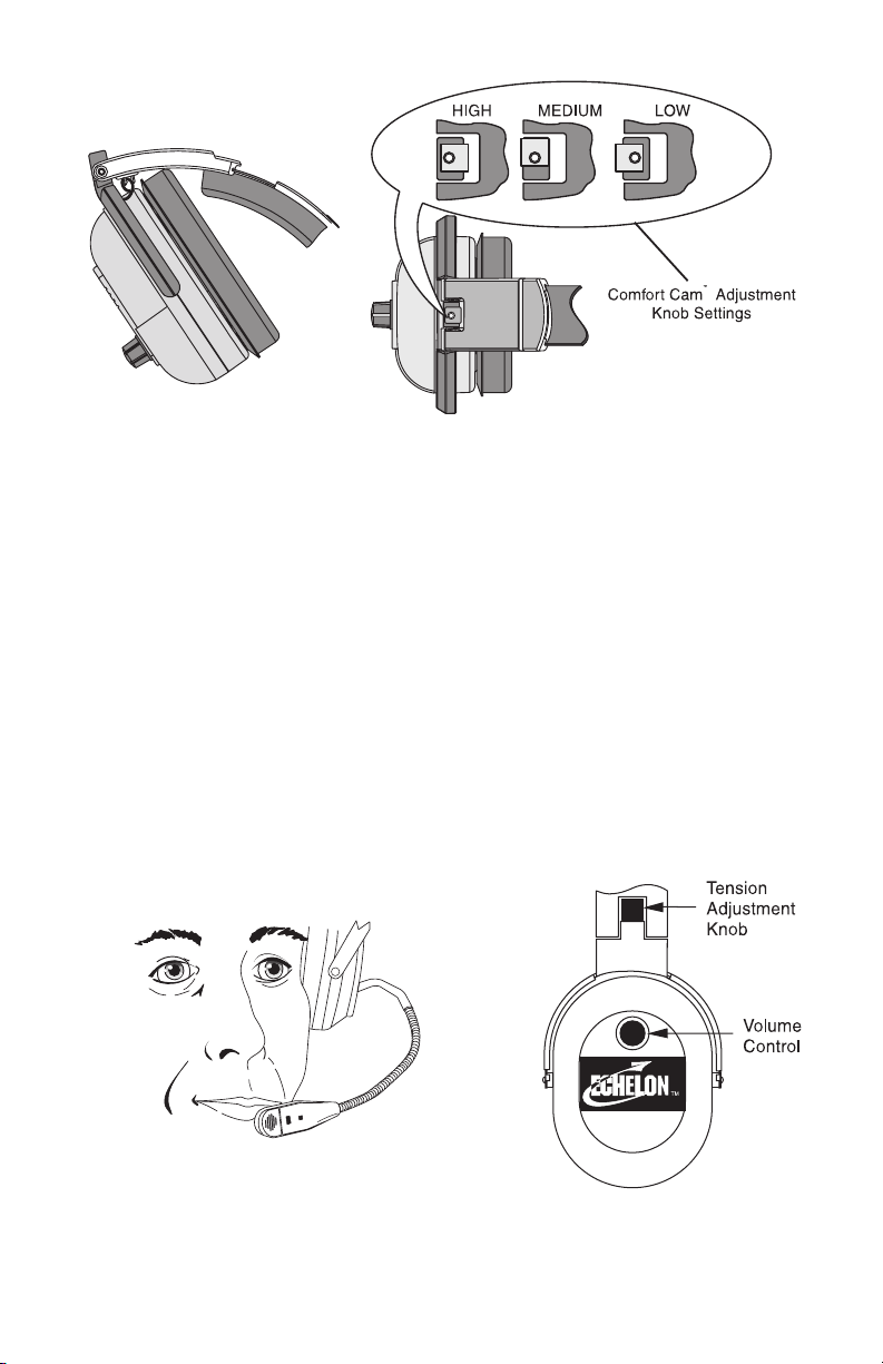
Figure 3. Headband Pressure Adjustment
7.Volume Adjustment Procedure
The following procedure is recommended to assure that there will
be sufficient radio volume in the event of a loss of power to the
headset.
a.Turn the headset power off.
b.Set the headset volume controls to the middle of their range.
c. USING THE AIRCRAFT RADIO VOLUME CONTROL, adjust
headphone volume for clear communication under typical
operating conditions.
d.Turn on the headset and adjust the volume controls ON THE
HEADSET to achieve clear communication with noise
reduction activated.
Figure 4. Microphone Placement Figure 5. Volume Control
Page 4
Page 7

Specifications
Receivers and Noise Reduction Circuits:
Reciever Type: Dynamic
Frequency Response: 50 Hz - 1.5 kHz
Sensitivity (Max. Volume): 95 ± 5 dB SPL (1 kHz, 1 mW input per earcup
side)
Impedance (Max. Volume): Stereo: 300 ohms per side, Monaural: 150
ohms
Stereo/Mono: Switch in cord allows Stereo or Monaural headset
operation.
Noise Reduction Power Consumption: 50 mW nominal, 1.5W peak per
side (dependent on noise level)
Microphone and Amplifier:
Element Type: Noise-canceling amplified electret
Frequency Response: 100 Hz - 5000 Hz
Sensitivity: -51 ±3 dB (ref:1 V/ µbar at 1 kHz with 12 Vdc 150 ohm AC
load)
Matching Impedance: 50-600 ohms
Gain Adjustment Range: ± 5 dB (clockwise rotation increases gain)
Operating Voltage (supplied by aircraft radio): 8-16 Vdc
Microphone Interface: Operates from a typical aircraft radio per RTCA
DO-170; 8 to 16 Volts DC with 470 ohm DC resistance, 150 ohm AC
resistance
Power:
To turn Power on and off simply plug or unplug the battery or Aircraft
Power Module.
Batteries: One 9V alkaline battery installed in the battery module.
ANR Battery Life: 40 hours minimum
Fail-Safe Mode:
If battery power is too low for normal ANR operation or if the power
module is disconnected, the headset will perform like a standard
headset maintaining communications with the aircraft radio.
Page 5
Page 8

General:
Cordage: Headset: Straight Y cord, 6 ft (1.8 m),
Aircraft Power Module: Straight cord, 3ft (0.9 m)
Headset Connections:
Power: 3.5 mm 2 conductor right angle plug for connections to
the battery module or aircraft power module.
Microphone: 0.206" diameter plug (PJ-068 equivalent)
Receiver: PJ-055 equivalent plug for receivers
Stereo/mono selector switch in the cord
Battery Module Connector:
3.5 mm 2 conductor jack for connection to the headset.
Aircraft Power Module Connectors:
Input power from aircraft: Straight cord, 6 ft (1.8 m) with 12V
fused power plug adapter.
Output power to headset: 3.5 mm 2 conductor jack.
Weights:
Headset with foam cushions: 18 oz. (560g)
Battery module with batteries: 3 oz. (85 g)
Aircraft Power Module: 2.2 oz. (62 g)
Color: Black
Ordering Information:
Echelon ANR 150 Headset, with electret mic, battery module, and
carrying case . .................................................... Catalog no. 300714-002
Battery module ................................................... Catalog no. 590564-002
Aircraft Power Module ........................................ Catalog no. 71046-002
Gel-filled ear cushions (package of 2) ................ Catalog no. 800027-002
Foam cushions (package of 2) ........................... Catalog no. 800027-003
Headband Pad ................................................... Catalog no. 800198-001
Replacement electret microphone ...................... Catalog no. 800136-002
Windscreen (electret) ......................................... Catalog no. 800456-000
Model PT-300 Push-to-Talk Switch* ................... Catalog no. 63966-000
Zippered Pouch .................................................. Catalog no. 590061-003
Clothing Clip ....................................................... Catalog no. 590637-000
* For aircraft without a push-to-talk switch, a portable push-to-talk switch
must be used
Page 6
Page 9

LIMITED WARRANTY — VALID ONLY IN UNITED STATES AND CANADA
TELEX Communications, Inc. (“Telex”) warrants to the user, who originally purchased the
product delivered with this card, that the product will be free from defects in material and
workmanship for the following periods after such date of purchase: Material 36 months,
workmanship 36 months. Telex will, at its option, repair or replace, free of charge, such defective
products subject to the following conditions:
1. Delivery of the product or parts postage prepaid to the Telex dealer, authorized service
facility or factory.
2. Determination by Telex that a defect exists and is covered by the limited warranty. Defects
due to alteration, repair by an unauthorized person, insertion of non-Telex parts, misuse,
accidental damage, use of the equipment for purposes other than those for which it was
designed, and the like, are not covered by this limited warranty and repairs thereof will
be subject to normal service charges.
3. Repairs and replacement parts are covered under this limited warranty only for the
unexpired term of the original limited warranty.
4. Products purchased from unauthorized dealers are not warranted.
5. You must fill out and return the attached registration card within 10 days after such
purchase or this limited warranty is void.
THIS LIMITED WARRANTY IS EXPRESSLY IN LIEU OF ANY EXPRESS OR IMPLIED
WARRANTY, INCLUDING ANY IMPLIED WARRANTY OF MERCHANTABILITY OR FITNESS
FOR A PARTICULAR PURPOSE WHICH EXTENDS BEYOND THE TERM HEREOF. THE
REMEDIES PROVIDED BY THIS LIMITED WARRANTY ARE THE ONLY REMEDIES
AVAILABLE TO ANY PERSON. NO PERSON HAS ANY AUTHORITY TO BIND TELEX TO
ANY REPRESENTATION OR WARRANTY OTHER THAN THOSE PROVIDED BY THIS
LIMITED WARRANTY. TELEX SHALL NOT BE LIABLE FOR ANY INCIDENTAL OR
CONSEQUENTIAL DAMAGES CAUSED BY FAILURE OR OTHERWISE OF THE PRODUCT.
Some states do not allow exclusions or limitations of incidental or consequential damages or
limitations on how long an implied warranty lasts, so the limitations or exclusions herein may
not apply to you. This warranty gives you specific legal rights, and you may also have other
rights which vary from state to state.
* HEADPHONES/HEADSETS DO NOT HAVE SERIAL NUMBERS ASSIGNED.
Page 7
Page 10

CUSTOMER SERVICE
For information or technical assistance, call or write to Telex at:
Customer Service Department
Telex Communications, Inc.
12000 Portland Ave. So.
Burnsville, MN 55337 U.S.A.
(952) 884-4051
When returning equipment for repair, please enclose an explanation of
the problem. And, if the equipment is covered under warranty, please
enclose a copy of your proof of purchase. The equipment must be
accompanied by documentation stating your name, return address, and
telephone number.
Return equipment for factory repair to:
Customer Service Department
Telex Communications, Inc.
1720 East 14th St.
Glencoe, MN 55336 U.S.A.
(320) 864-3177
Warranty Repairs - If in warranty, no charge will be made for the repairs.
Equipment being returned for warranty repair must be sent prepaid and
will be returned prepaid.
Non-Warranty Repairs - Equipment that is not under warranty must be
sent prepaid to Telex. If requested, an estimate of repair costs will be
issued prior to service. Once your approval for repair, and repair of
equipment is completed, the equipment will be returned on a collect
basis. Collect charges may be avoided by sending a signed check for
payment in full along with your signed estimate approval form (the
estimate includes the shipping charge).
Page 8
Page 11

Notes
Page 12

38110-010 Rev B 4/02
 Loading...