

Page 1

User Instructions
Air 3500
Noise Reduction Headset
38110-012 Rev C 10/2010
Page 2

Air 3500 Noise Reduction Headset
PROPRIETARY NOTICE
The product information and design disclosed herein were
originated by and are the property of Bosch Security Systems, Inc. Bosch reserves all patent, proprietary design,
manufacturing, reproduction, use and sales rights thereto,
and to any article disclosed therein, except to the extent
rights are expressly granted to others.
C
OPYRIGHT NOTICE
Copyright 2010 by Bosch Security Systems, Inc. All
rights reserved. Reproduction, in whole or in part, without
prior written permission from Bosch is prohibited.
W
ARRANTY AND SERVICE INFORMATION
For warranty and service information, refer to the appropriate web site below:
Headsets................. www.intercomheadsets.com/warranty
RTS................................ www.rtsintercoms.com/warranty
RTSTW...................................... www.rtstw.com/warranty
AudioCom ................. www.telexaudiocom.com/warranty
RadioCom................... www.telexradiocom.com/warranty
USTOMER SUPPORT
C
Technical questions should be directed to:
Customer Service Department
Bosch Security Systems, Inc.
Attn: Service
8601 E Cornhusker Hwy
Lincoln, NE 68507
800-898-6723
2
Page 3

Air 3500 Noise Reduction Headset
FIGURE 1. Air 3500 Noise Reduction Headset
3
Page 4

Air 3500 Noise Reduction Headset
4
Page 5

Table
of
Contents
Headband Size Adjustment ..........................................................3
Headband Pressure Adjustment ...................................................4
Left or Right Side Microphone Placement ..................................5
Permanently Changing Microphone Side ....................................5
Connection ...................................................................................6
Stereo Mono Switch (fixed-wing version only) ..........................7
Volume Adjustment .....................................................................7
Microphone Gain Adjustment .....................................................8
Ear Cushion Replacement ............................................................8
Head Pad Replacement ................................................................9
Mic Element Removal .................................................................9
Specifications .............................................................................10
Exploded View Parts List ..........................................................11
Page 6

2
Page 7

Headband Size Adjustment
To adjust the headband size, do the following:
> Move the earcup sliders up or down on the headband.
Size is properly adjusted when the earcups are centered over the ears.
IMPORTANT: It is important to adjust both sides of the headband the
same to keep the headband and pad properly centered over
the head.
FIGURE 1. Headband Size Adjustment
3
Page 8
Headband Pressure Adjustment
HIGH MEDIUM LOW
Comfort Cam™
ADJUSTMENT KNOB SETTINGS
There are three (3) pressure settings. Increasing the pressure improves the seal
between the earcup and the head for greater noise reduction.
To change the pressure setting, do the following:
1. Fold the earcup in as shown in Figure 2.
2. Rotate the Comfort Cam adjust knob to the desired setting.
3. Repeat for the other earcup.
IMPORTANT: Both sides of the headband should be set to the same
pressure setting to keep the headband properly centered on
the head.
FIGURE 2. Headband Pressure Adjustment
4
Page 9

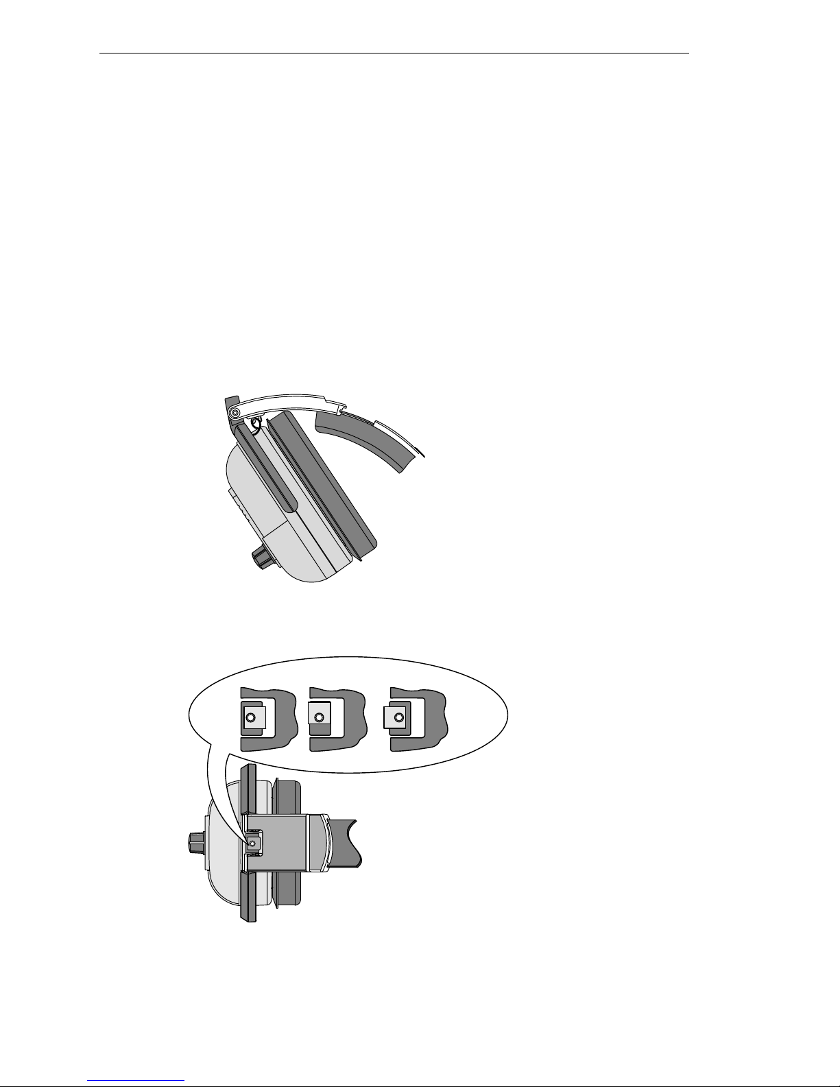
Left or Right Side Microphone Placement
To place the microphone, do the following:
1. Rotate the boom, as shown in Figure 3.
FIGURE 3. Rotating and Reshaping the Boom
2. Reshape the boom so the microphone is at the corner of the mouth.
Permanently Changing Microphone Side
To permanently change the side of the headset the microphone is on, do the
following:
1. Press the release catch and carefully pull out the mic element.
Avoid pulling the connecting wires.
5
Page 10
2. Turn the microphone element over and reinsert it as shown in Figure 4.
RELEASE CATCH
MIC ELEMENT
To Radio Headset Jack
AIR 3500
HELICOPTER VERSION
AIR 3500
FIXED WING VERSION
To Radio Receiver "OUT" Jack
Mono/Stereo
Headphone Switch
To Radio Microphone "IN" Jack
FIGURE 4. Mic Element Rotation
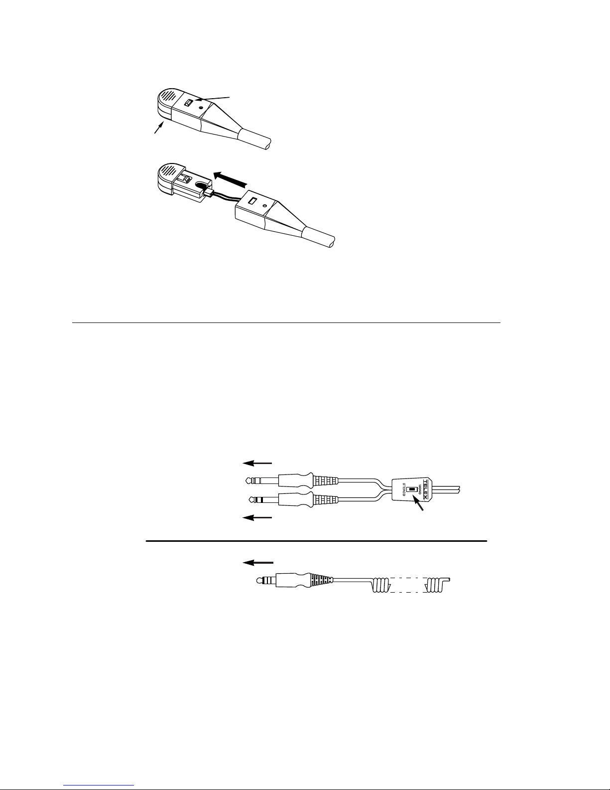
Connection
To connect the headset, do the following:
Using Figure 5, connect the headset to the aircraft radio or intercom
system.
FIGURE 5. Air 3500 Connectors
6
Page 11

Stereo Mono Switch (fixed-wing version only)
This switch is located on the y-cord (Figure 5).
To set the stereo mono switch, do the following:
Set the switch to stereo for aircraft with stereo intercom systems.
OR
Set the switch to mono for monaural intercom system or for direct
connection to the aircraft radio.
Volume Adjustment
To adjust the volume, do the following:
When the microphone is worn on the left side, volume is increased by
rotating the top of the controls clockwise.
OR
When the microphone is worn on the right side, volume is increased by
rotating the top of the controls counter-clockwise.
7
Page 12

Microphone Gain Adjustment
MIC GAIN
ADJUSTMENT
ACCESS
IMPORTANT: The microphone gain has been factory-adjusted to the nominal
level required for FAA certification, and it should normally not
require readjustment. Readjustment by a qualified avionics
technician is recommended.
To access the gain trimmer, do the following:
1. Insert a small flatblade screwdriver in the mic element. (Figure 6)
FIGURE 6. Air 3500 Mic Gain Adjustment
2. Rotate the trimmer clockwise to increase the gain.
Ear Cushion Replacement
To remove an old ear cushion, do the following:
Grasp the old ear cushion and pull it off the earcup.
To install a new ear cushion, do the following:
1. Starting at the top of the earcup, place the flap on the back of the ear
cushion over the lip along the top of the earcup.
2. Pull the bottom of the ear cushion down over the lip at the bottom of the
earcup.
8
Page 13

Head Pad Replacement
RELEASE CATCH
MIC ELEMENT
To replace the head pad, do the following:
1. Unsnap the old head pad.
2. Pry the head pad off the headband (it is held in place with adhesive).
3. Peel off the adhesive backing on the new head pad.
4. Attach the new pad to the headband.
IMPORTANT: Make sure the overhead cord is inside the flaps of the head
pad.
5. Snap the flaps closed.
Mic Element Removal
To remove the mic element, do the following:
1. Press the release catch on the microphone element.
FIGURE 7. Mic Element Removal for Replacement
2. Carefully pull out the element.
NOTE: Avoid pulling on the microphone wires.
3. Pull the plastic connector housing to unplug the microphone element.
9
Page 14

Specifications
Receivers
Type: Dynamic
Impedance: Accepts 150-600 Ohm sources
Frequency Response: 350Hz -3.0kHz ±6dB
Sensitivity: 90 ±5dB SPL for 1mW, 1kHz input
Maximum Power Input: 30mW
Microphone/Amplifier Assembly
Microphone Type: Noise-cancelling electret condenser
Output Impedance:
50 Ohms (designed for radio input impedances from 50-600 Ohms
Frequency Response: 100Hz – 3.5kHz
Sensitivity: -53 +2/-1dB (ref: 1V/μbar)
Operating Voltage: 8-16 Vdc
Cords and Plugs
Air 3500, general aviation version:
Cord: 5.5ft (1.7m) “Y” cord with stereo/mono selector switch
Receiver Plug: 1/4” stereo phone plug
Microphone Plug: PJ-068 equivalent
Air 3500HE, Helicopter version:
Cord: 5.5ft (1.7m) coiled cord
Plug: TP-120, U-93A/U, U-174/U equivalent
10
Page 15

Exploded View Parts List
Item
No.
1 800198-001 Replacement Head Pad 1
2 19652-057 Coiled Cord (helicopter version only) 1
3 545015-000 Stereo/Mono Switch
4 800138-000 Y-cord, Complete W/Switch
5 590060-000 Cord Clip (fixed-wing version only) 1
6 800136-000 Microphone Element Assembly 1
7 800147-001 Foam Ear Pads (set of 2) 1
8 800027-002 Gel-filled Ear Pads (set of 2) 1
9 700498-000 Foam Top Cover 4
10 51856-003 Screw, Plastite, #2-56 x .5” 4
11 590055-001 Headphone Driver Assembly 2
Part No. Description Qty
(fixed wing-version only)
(fixed-wing version only)
1
1
12 700487-004 Foam Liner 2
13 700487-002 Foam Liner (non-boom side only) 1
14 700487-000 Foam Liner (boom side only) 1
15 54131-008 Potentiometer with Nut and Lockwasher
(non-boom side)
16 54131-009 Potentiometer with Nut and Lockwasher
(boom side)
17 580001-001 O-ring 2
18 700453-000 Tension Adjustment Knob 2
19 53435-000 Volume Knob 2
20 56517-000 Volume Knob Insert 2
21 700449-000 Wire Boot 2
22 51709-000 Tie Wrap 2
23 57012-001 Windscreen 1
2
2
11
Page 16

1
2
3
4
5
6
87
9
10
11
12 13
16a
17
14
16c
19
20
22
21
18
16b
15b
15c
15a
23
FIGURE 8. Exploded View for Parts Replacement
12
Page 17

FIGURE 9. Wiring Diagram for Fixed-Wing Version
RED
BLK
WHT
RECEIVERS
5K
5K
BLK
WHT
BLK
MICROPHONE
1
2
WHT
BLU
RED
BLK
STEREO/MONO
SWITCH
13
2
13
2
300 300
WHT
OVERHEAD
Boom SideNon-Boom Side
RED
BLK
WHT
RECEIVERS
5K
5K
BLK
WHT
BLK
MICROPHONE
1
2
BLU
RED
BLK
13
2
13
2
NC
NC
NC
300 300
WHT
WHT
OVERHEAD
Boom SideNon-Boom Side
FIGURE 10. Wiring Diagram for Helicopter Version
13
Page 18

Bosch Security Systems, Inc.
www.boschcommunications.com
12000 Portland Ave South
Burnsville, MN 55337 U.S.A.
 Loading...