

Page 1
®
Te l e x
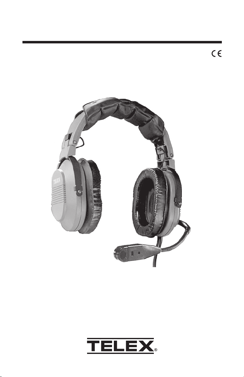
User Instructions
Air3100 Headset
Air3100L Headphone
Page 2
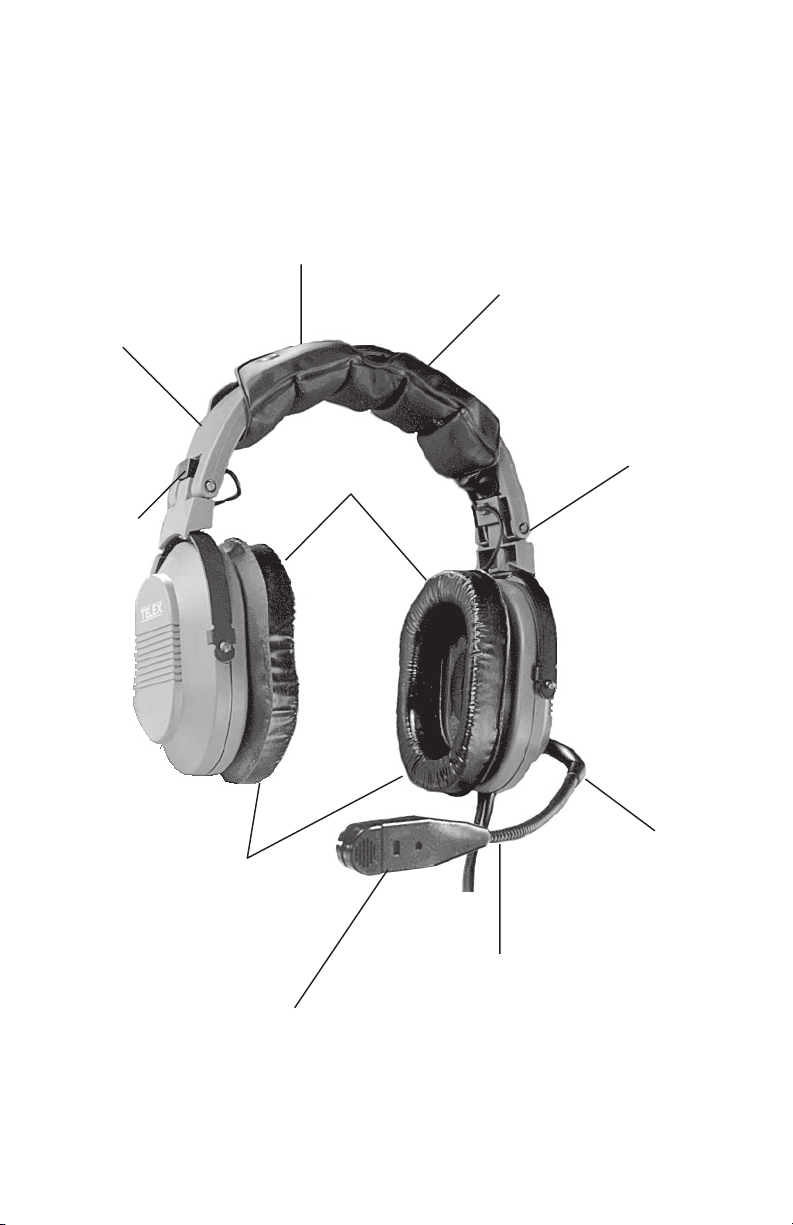
Detented Sliders
Adjust to
Any Size Head
Tension
Adjust Knob
Unique
Design
Replaceable
Ear Cushions
Replaceable
Wide Head Pad
Earcups Pivot on
Two Planes to
Conform to Wearer
Replaceable
Ear Cushions
Noise Canceling
Electret Microphone
Patented Ball and Socket
Jointed Boom Rotates
Overhead for Mic
Placement on Either
Side of Head
Flexible Boom Permits
Precise Mic Placement
Figure 1
Air3100 Reference View
Page 3

General Description
The Telex Air3100 is a medium-weight noise-reduction headset with
amplified, noise-canceling, electret microphones. The Telex Air3100L is a
headphone only and does not have a microphone. They both have a
noise reduction rating of 21 dB, and are suitable for use in moderately
noisy aircraft. All models feature a unique headband design that
distributes ear cushion pressure evenly over the entire ear with no
pressure points, unlike conventional designs which apply more pressure
on the bottom of the ear than on the top. An added advantage of this
design is that the headset folds into an extremely compact shape for
storage. The Air3100 headset is approved for aircraft use under FAA
TSO’s C57a and C58a. The Air3100L headphone is approved for aircraft
use under FAA TSO’s C57a.
Design Features
(See Figure 1)
Comfortable foam-filled headband pad and ear cushions. The headband
pad evenly distributes the headset weight, with no pressure points, for
maximum wearer comfort. The ear cushions combine comfort and light
weight with excellent acoustic seal. An outer urethane layer ensures long
life. Gel-filled ear cushions are also available for this headset for users
who prefer this type. All cushions are field-replaceable.
Boom Microphone: The boom arm features a sealed ball-and-socket
joint and flexible boom for precise microphone placement on any head
size. The boom rotates overhead for microphone placement on either
side of the head. The microphone cartridge features a noise-canceling
electret element. The cartridge snaps on and off for easy replacement.
The microphone amplifier is in the microphone cartridge. It operates on
current supplied by the aircraft radio via the microphone jack. The
amplifier output level is adjustable through an opening in the microphone
assembly.
Cordage: The microphone cordage is protected inside the boom arm.
Shielded wire throughout the headset protects against RFI and EMI.
Strain-reliefs on all cords provide maximum durability.
Sound Attenuation Data: The following measurements for the Telex
Air3100 and AIR3100L Headsets were made according to the American
National Standard Institute (ANSI) S3.19-1974 by Paul Michael and
Associates. These laboratory-derived attenuation data are for comparison
purposes only, as the amount of protection afforded in field use is often
significantly lower depending upon how the headphones are fitted and
worn.
)Bd(ycneuqerFretneC521052005000100020513000400360008
)Bd(noitaunettA naeM7.519.717.329.621.821.438.833.730.83
)Bd(noitaiveDdradnatS4.28.14.22.21.21.35.20.32.2
sdnuoP5.2=ecroFdnabdaeH
Bd12=)RRN(gnitaRnoitcudeResioN
Page 1
Page 4
Operation
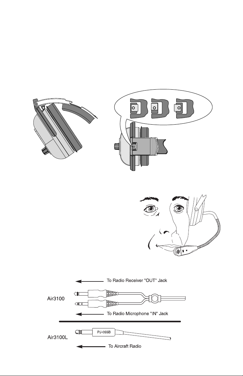
Headband Pressure Adjustments
There are three pressure settings. Increasing the pressure will improve
the seal between the earcup and the head for greater noise reduction. To
change the pressure setting, remove the headset and fold the earcup
inward as shown, then rotate the adjustment knob to the desired setting.
Repeat for both earcups. Both sides of the headband should be set to the
same pressure setting to keep the headband properly centered on the
head.
HIGH MEDIUM LOW
Figure 2
Boom Microphone Placement
1. Rotate the entire boom overhead to
wear the microphone on either the
right or left side of the head.
2. For best noise canceling, position the
microphone as close to the mouth as
possible and speak in a normal voice.
(See figure 3)
3. When the microphone is not in use, it
may be swung slightly away from the
mouth.
Connections
Figure 3
Page 2
Page 5

Microphone Gain Adjustment
The microphone gain has been factoryadjusted to the nominal level required for
FAA certification, and it should normally
not require readjustment. Readjustment
by a qualified avionics technician is
recommended. To access the gain trimmer, insert a
small flat-blade screwdriver through the access hole in the
mic assembly. Clockwise rotation of the trimmer increases
gain.
Mic Assembly Removal
Press the release catch on the microphone
assembly, and carefully pull out the
assembly. Avoid pulling the microphone
wires. Pull on the plastic connector
housing to unplug the microphone
assembly.
Air3100 & Air 3100L Headset Wiring Diagram
MIC GAIN
ADJUSTMENT
ACCESS
Air3100 Microphone Wiring Diagram
Page 3
Page 6

Exploded View Parts List (See Figure 4)
.oNmetI.oNtraPnoitpircseD0013L0013
1
2100-730008thgiR,ylbmessApucraE11
3000-580007tfeL,revoC11
4100-580007thgiR,revoC11
9000-301008tunoDmaoF/wylbmessArevieceR22
01000-631008ylbmessAenohporciM1–
11200-684007ylbmessAmooB1–
91000-18307potSmooB1–
02000-700007flaHllaB2–
12100-490007gnirpSllaB1–
22
52400-65815gnoL"4/1x02-4#,etitsalP,wercS1–
62030-65815gnoL"8/5x02-4#,etitsalP,wercS44
72200-041007reniLpuC22
82000-141007revoCrevieceR22
92200-54195tunoDmaoF22
33
43100-431007pilCdroC,noisurtxE22
53
63100-891008dapdaeH11
73
83100-420008maoF,noihsuC22
93000-46385gnoL"82,droCdaehrevORARA
14000-736095pilCgnihtolC11
000-730008tfeLmooB,ylbmessApucraE1–
200-730008tfeLmooBoN,ylbmessApucraE–1
031-47006ylbmessAdroC-Y1–
091-15006ylbmessAdroC–1
500-451008ylbmessAdnabdaeH1–
600-451008ylbmessAdnabdaeH–1
100-354007bonKpmalC2–
000-354007bonKpmalC–2
700-65436feileRdneB1–
300-65436feileRdneB–1
300048 Rev BN
300448 Rev G
Page 4
Page 7

boom (11) . Place boom stop (19) into slot
on boom (11) . Push inside ball half (20) to hold
boom stop (19) into place. Orient ball half (20)
with cup assembly so that boom will swing
over but not under the earcup assembly (1).
1 NOTE: Slip outside ball (20) around
Figure 4
Page 5
Page 8

Specifications
Receivers:
Type: Dynamic
Frequency Response: 350 Hz - 6 kHz
Sensitivity: 100 ±5 dB SPL (1 kHz, 1 mW input)
Impedance (at 1 kHz): 150 ohms (receivers wired in parallel)
Microphone and Amplifier: (AIR3100 only)
Element Type: Noise-canceling electret
Frequency Response: 100 Hz - 3.5 kHz
Sensitivity: -53 +2/-1 dB (ref:1 V/ µbar at 1 kHz with 12 Vdc supply
voltage and 100 ohm load).
Matching Impedance: 50-600 ohms
Gain Adjustment Range: ± 5 dB (clockwise rotation increases gain)
Operating Voltage (supplied by aircraft radio): 8-16 volts dc
Cordage:
Air3100: Straight Y-cord, 5 ft (1.5 m)
Air3100L: Straight, 5 ft (1.5 m)
Connectors:
Air3100: PJ-068 equivalent plug for radio mic jack; PJ-055 equivalent
plug for radio phone jack
Air3100L: PJ-055 plug or equivalent
Weight:
Gross Weight: Approximately 16oz. (454 g)
Effective Head Weight: Approximately 14.2 oz. (403 g)
Color: Gray
Ordering Information
(See Exploded View Parts List for a complete listing of replacement parts)
Air3100 Headset .................................................. Catalog no. 300048-200
Air3100L Headphone (listen only) ........................ Catalog no. 300448-000
Thin-skin foam ear cushions (set of two) ............ Catalog no. 800027-003
Gel-filled ear cushions (set of two)....................... Catalog no. 800027-002
Head pad ............................................................. Catalog no. 800198-001
Microphone cartridge ........................................... Catalog no. 800136-000
Microphone windscreen ......................................... Catalog no. 57012-001
Model PT-300 Portable Push-To-Talk Switch* ...... Catalog no. 63966-000
* For aircraft without a push-to-talk switch, a portable push-to-talk switch
must be used.
Page 6
Page 9

LIMITED WARRANTY — VALID ONLY IN UNITED STATES AND CANADA
TELEX Communications, Inc. (“Telex”) warrants to the user, who originally purchased the
product delivered with this card, that the product will be free from defects in material and
workmanship for the following periods after such date of purchase: Material 36 months,
workmanship 36 months. Telex will, at its option, repair or replace, free of charge, such
defective products subject to the following conditions:
1. Delivery of the product or parts postage prepaid to the Telex dealer, authorized
service facility or factory.
2. Determination by Telex that a defect exists and is covered by the limited warranty.
Defects due to alteration, repair by an unauthorized person, insertion of non-Telex
parts, misuse, accidental damage, use of the equipment for purposes other than
those for which it was designed, and the like, are not covered by this limited warranty
and repairs thereof will be subject to normal service charges.
3. Repairs and replacement parts are covered under this limited warranty only for the
unexpired term of the original limited warranty.
4. Products purchased from unauthorized dealers are not warranted.
5. You must fill out and return the attached registration card within 10 days after such
purchase or this limited warranty is void.
THIS LIMITED WARRANTY IS EXPRESSLY IN LIEU OF ANY EXPRESS OR IMPLIED
WARRANTY, INCLUDING ANY IMPLIED WARRANTY OF MERCHANTABILITY OR
FITNESS FOR A PARTICULAR PURPOSE WHICH EXTENDS BEYOND THE TERM
HEREOF. THE REMEDIES PROVIDED BY THIS LIMITED WARRANTY ARE THE ONLY
REMEDIES AVAILABLE TO ANY PERSON. NO PERSON HAS ANY AUTHORITY TO
BIND TELEX TO ANY REPRESENTATION OR WARRANTY OTHER THAN THOSE
PROVIDED BY THIS LIMITED WARRANTY. TELEX SHALL NOT BE LIABLE FOR ANY
INCIDENTAL OR CONSEQUENTIAL DAMAGES CAUSED BY FAILURE OR OTHERWISE
OF THE PRODUCT.
Some states do not allow exclusions or limitations of incidental or consequential damages
or limitations on how long an implied warranty lasts, so the limitations or exclusions herein
may not apply to you. This warranty gives you specific legal rights, and you may also have
other rights which vary from state to state.
Page 7
Page 10

NOTES
Page 11

NOTES
Page 12

38110-015 Rev B 6/02
 Loading...