

Page 1

Model ADHB-4
Technical Manual
up to and including version 1.00
LIT000458000 Rev A March 2010
Page 2

PROPRIETARY NOTICE
PHONE NUMBERS
The product information and design disclosed herein were originated by
and are the property of Bosch Security Systems, Inc. Bosch reserves all
patent, proprietary design, manufacturing, reproduction, use and sales
rights thereto, and to any article disclosed therein, except to the extent
rights are expressly granted to others.
COPYRIGHT NOTICE
Copyright 2010 by Bosch Security Systems, Inc. All rights reserved.
Reproduction, in whole or in part, without prior written permission from
Bosch is prohibited.
WARRANTY NOTICE (LIMITED)
All Bosch manufactured signaling products are guaranteed against
malfunction due to defects in materials and workmanship for three (3)
years, beginning at the original date of purchase.If such a malfunction
occurs, the product will be repaired or replaced (at our option) without
charge during the three (3) year period, if delivered to the Bosch factory.
Warranty does not extend to damage due to improper repairs, finish or
appearance items, or malfunction due to abuse or operation under other
than the specified conditions, nor does it extend to incidental or
consequential damages. Some states do not allow the exclusion or
limitation of incidental or consequential damages, so the above
limitation may not apply to you. This warranty gives the customer
specific legal rights, and there may be other rights which vary from state
to state.
Sales:
Phone ...................................................................(800) 752-7560
Fax........................................................................(402) 467-3279
E-mail...........................................TelexDispatch@us.bosch.com
Customer Service Repair:.................................................(800) 553-5992
Technical Support:
Phone ...................................................................(800) 898-6723
E-mail ........................ TelexDispatchtechsupport@us.bosch.com
CLAIMS
No liability will be accepted for damages directly or indirectly arising
from the use of our materials or from any other causes. Our liability shall
be expressly limited to replacement or repair of defective materials.
WARNING
This is a class A product. In a domestic environment this product may
cause radio interference, in which case the user may be required to take
adequate measures.
FACTORY SERVICE CENTER
Factory Service Center
Bosch Security Systems, Inc.
Radio Dispatch Products
8601 East Cornhusker Highway
Lincoln, Nebraska, 68507
Page 3

Table
of
Contents
Overview ...............................................................11
Computer System Requirements ...........................12
Features ................................................................13
Optional Hardware ..............................................14
Hardware Overview .............................................15
ADHB-4 MAINBOARD .................................................15
IGITAL CONTROL BOARD .......................................... 15
D
EYPAD BOARD ..........................................................15
K
XLR C
ONNECTOR BOARD ...........................................15
Controls and Indicators ........................................16
FRONT PANEL CONTROLS AND INDICATORS ................16
ACK PLANE CONNECTIONS .......................................17
B
IDE PANEL CONNECTIONS ......................................... 17
S
Specifications ........................................................18
Installation ............................................................19
ADHB-4 Mounting ................................................20
MOUNTING .................................................................20
ADHB-4 M
NDERSIDE MOUNTING ..............................................20
U
T
OPSIDE MOUNTING ...................................................21
OUNTING BRACKETS .................................20
ADHB-4 Connections ...........................................22
USB PORT ..................................................................22
10/100 NETWORK P
PHONE J
NENA J
ACK ............................................................22
ACK ...............................................................22
NENA Phone Connector ........................................23
RJ-12 Connector ....................................................23
FOOTSWITCH J
3-Pin Connector .....................................................23
ACCESSORY P
AUX TTL Level Inputs ......................................24
Form C Relay Contacts .......................................24
DB-15 Connector ...................................................24
REMOTE HEADSET (1
DESK MIC J
ACK .......................................................25
RJ11 Connector.......................................................25
MIC (XLR) C
ONNECTOR ............................................25
Speaker default settings: .. ..... .... ..........................26
POWER J
ACK ............................................................26
ORT ..........................................22
ACK .................................................23
ORT ...................................................24
AND 2) CONNECTORS ..........25
HEADSET J
ACK ........................................................ 26
Connect ADHB-4 Hardware ................................27
C-Soft Installation ................................................27
ADHB-4 Driver Installation .................................27
INSTALL THE ADHB-4 DRIVER WITH WINDOWS 7 ....... 28
NSTALL THE ADHB-4 DRIVER WITH WINDOWS XP .... 30
I
PPLY POWER TO THE ADHB-4 ................................. 34
A
C
ONNECT THE USB CABLE ........................................ 34
Web Browser Configuration .................................35
Home Link .............................................................36
Account Management Window .............................37
USERNAME FIELD ...................................................... 37
ASSWORD FIELD ....................................................... 37
P
N
EW PASSWORD FIELD .............................................. 37
ONFIRM PASSWORD FIELD ....................................... 38
C
UBMIT BUTTON ........................................................ 38
S
Ethernet Setup Window ........................................39
USE DHCP CHECK BOX ............................................ 39
U
NIT IP ADDRESS FIELD ............................................ 40
UBNET MASK FIELD ................................................. 40
S
EFAULT GATEWAY FIELD ......................................... 40
D
DNS A
S
S
S
S
S
MAC A
S
K
S
DDRESS 1–3 FIELDS ........................................ 40
YSTEM MANAGER ENABLE CHECK BOX .................... 40
YSTEM MANAGER MULTICAST ADDRESS FIELD ......... 41
YSTEM MANAGER INCOMING PORT FIELD ................ 41
YSTEM MANAGER OUTGOING PORT FIELD ............... 41
YSTEM MANAGER TTL FIELD ................................... 41
DDRESS FIELD ................................................ 41
ERIAL NUMBER FIELD .............................................. 41
ERNEL VERSION FIELD ............................................ 41
UBMIT BUTTON ........................................................ 41
Gain Setup Window ..............................................42
RJ11 DESK MIC SLIDER ............................................. 42
H
EADSET MIC SLIDER ................................................ 43
XLR D
NENA I
NENA O
C
U
S
ESK MIC SLIDER ..............................................43
NPUT SLIDER ................................................. 43
UTPUT SLIDER .............................................. 43
OMMON RECORD VOL SLIDER ................................. 43
NSELECT RECORD VOL SLIDER ................................ 43
UBMIT BUTTON ........................................................ 44
Page 4

System Setup Window .......................................... 44
NAME FIELD ...............................................................45
IC CONNECTOR DROP DOWN MENU ........................ 45
M
IC TYPE DROP DOWN MENU ...................................45
M
P
HANTOM POWER DROP DOWN MENU ....................... 45
RHB 1 H
RHB 2 H
C
ONTROLLER HEADSET DROP DOWN MENU ...............46
RHB 1 A
RHB 2 A
C
ONTROLLER HEADSET AUDIO DROP DOWN MENU ...46
EADSET MIC #1–#4 RADIO BUTTONS .......................47
H
EADSET MIC DISABLE RADIO BUTTON ......................47
H
RHB 1 M
RHB 1 M
RHB 2 M
RHB 2 M
ESK MIC #1–#4 RADIO BUTTONS ............................. 47
D
ESK MIC DISABLE RADIO BUTTON ...........................48
D
H
EADSET MIC #1–#4 RADIO BUTTONS .......................48
EADSET MIC DISABLE RADIO BUTTON ......................48
H
RHB 1 M
RHB 1 M
RHB 2 M
RHB 2 M
D
ESK MIC #1–#4 RADIO BUTTONS ............................. 49
ESK MIC DISABLE RADIO BUTTON ...........................49
D
EADSET MIC #1–#4 RADIO BUTTONS .......................50
H
H
EADSET MIC DISABLE RADIO BUTTON ......................50
RHB 1 M
RHB 1 M
RHB 2 M
RHB 2 M
ONSOLE GENERATED PTT RADIO BUTTON ...............51
C
H
EADSET PTT #1–#6 RADIO BUTTONS ....................... 51
EADSET PTT NO PRIORITY RADIO BUTTON .............. 51
H
RHB 1 PTT #1–#6 R
RHB 1 PTT N
RHB 2 PTT #1–#6 R
RHB 2 PTT N
ESK MIC PTT #1–#6 RADIO BUTTONS .....................51
D
D
ESK MIC PTT NO PRIORITY RADIO BUTTON ............52
OOTSWITCH PTT #1–#6 RADIO BUTTONS .................52
F
OOTSWITCH PTT NO PRIORITY RADIO BUTTON ........52
F
C
ONSOLE GENERATED PTT #1–#6 RADIO BUTTON ....52
LCD B
HANGE IP ON DISPLAY CHECK BOX ........................52
C
C
OMMON RECORD UNSEL CHECK BOX ......................52
UBMIT BUTTON .........................................................52
S
EADSET DROP DOWN MENU ........................46
EADSET DROP DOWN MENU ........................46
UDIO DROP DOWN MENU ............................46
UDIO DROP DOWN MENU ............................46
IC #1–#4 RADIO BUTTONS ...........................47
IC DISABLE RADIO BUTTON .........................47
IC #1–#4 RADIO BUTTONS ...........................47
IC DISABLE RADIO BUTTON .........................47
IC #1–#4 RADIO BUTTONS ...........................48
IC DISABLE RADIO BUTTON .........................48
IC #1–#4 RADIO BUTTONS ...........................48
IC DISABLE RADIO BUTTON .........................48
IC #1–#4 RADIO BUTTONS ...........................50
IC DISABLE RADIO BUTTON .........................50
IC #1–#4 RADIO BUTTONS ...........................50
IC DISABLE RADIO BUTTON .........................50
ADIO BUTTONS ..........................51
O PRIORITY RADIO BUTTON .................. 51
ADIO BUTTONS ..........................51
O PRIORITY RADIO BUTTON .................. 51
ACKLIGHT FIELD .............................................52
System Status ........................................................ 53
REFRESH STATUS LINK ...............................................53
AUX 1 I
AUX 2 I
R
R
NPUT .............................................................54
NPUT .............................................................54
ELAY 1 FIELD ...........................................................54
ELAY 2 FIELD ...........................................................54
IC LEVEL FIELD .......................................................54
M
NENA L
H
RHB 1 C
RHB 2 C
H
RHB 1 PTT F
RHB 2 PTT F
S
PEAKERS 1–6 FIELD ..................................................55
D
OOTSWITCH MONITOR FIELD ....................................56
F
NENA H
D
OOTSWITCH PTT FIELD ............................................56
F
EVEL FIELD ...................................................54
EADSET CONNECTION FIELD ....................................55
ONNECTION FIELD ........................................55
ONNECTION FIELD ........................................55
EADSET PTT FIELD ..................................................55
IELD ......................................................55
IELD ......................................................55
ESK MIC MONITOR FIELD ........................................56
OOK FIELD ...................................................56
ESK MIC PTT FIELD ................................................56
Save Parameters .................................................. 57
SAVE PARAMETERS BUTTON ........................................57
R
ESTORE FACTORY DEFAULT BUTTON ........................57
ESET ADHB-4 BUTTON ............................................58
R
LCD Display ........................................................ 59
Volume Buttons .................................................... 59
VOLUME LEVEL ..........................................................59
RONT LED INDICATOR ..............................................59
F
HANTOM POWER LED INDICATOR ............................60
P
Normal Operation Mode ...................................... 60
USB Indicator Icon ..............................................60
Status Icons ..........................................................61
SPEAKER STATUS ICONS ..............................................61
TATUS ICON ......................................................61
AUX S
ELAY STATUS ICON ....................................................62
R
NENA S
OLUME INDICATOR ICON ..........................................62
V
PTT I
TATUS ICON ...................................................62
NDICATOR ICONS ...............................................63
Programming Mode ............................................. 63
NETWORK MENU .........................................................63
C
LOCK MODE MENU ..................................................64
B
ACKLIGHT MENU ......................................................65
YSTEM INFO MENU ....................................................65
S
C-Soft Controls .................................................... 66
C-SOFT STATUS BAR ...................................................66
PEAKER INDICATIONS ................................................66
S
Single Speaker Icon ...............................................66
Common Unselect Speaker Icon ............................66
Disconnected Speaker Icon ....................................66
Muted Speaker Icon ...............................................66
Speaker Setup in C-Soft ....................................... 67
UNSELECT AUDIO .......................................................67
ER LINE UNSELECT WINDOW ....................................67
P
PEAKER 2–6 RADIO BUTTONS ...................................67
S
P
OSITIONAL + SPEAKER 2 CHECK BOX .......................67
ET BUTTON ...............................................................68
S
IRR S
PEAKER WINDOW ...............................................69
ADHB-4 G
UTTON SPEAKER NUMBERS ON CHECK BOX .............69
B
A
LWAYS ON RADIO BUTTON ........................................70
LOBAL WINDOW ........................................69
Page 5

OFF WHEN HEADSET CONNECTED RADIO BUTTON .....70
INE NAME COLUMN ..................................................70
L
NSELECT SPEAKER # COLUMN ..................................70
U
Per Line Unselect ................................................70
ADHB-4 V
OLUME CONTROL WINDOW ........................71
Overview ...............................................................73
COMPATIBLE HEADSETS ..............................................73
Features ................................................................73
Controls and Indicators ........................................74
FRONT PANEL CONNECTIONS, CONTROLS AND
I
NDICATIONS ...............................................................74
ACK PANEL CONNECTION .........................................74
B
Mounting ...............................................................75
DB-9 Cable ...........................................................75
RHB Installation ...................................................75
Configuration ........................................................76
Page 6

Page 7

List
of
Figures
FIGURE 1. ADHB-4 Front Panel Controls and Indicators ....................................................................................16
FIGURE 2. ADHB-4 Back Plane Connections .......................................................................................................17
FIGURE 3. ADHB-4 Side Panel Connections ........................................................................................................17
FIGURE 4. ADHB-4 Underside Mounting .............................................................................................................20
FIGURE 5. ADHB-4 Topside Mounting .................................................................................................................21
FIGURE 6. NENA Phone Connector ......................................................................................................................22
FIGURE 7. RJ-12 Pin Outs—NENA phone ............................................................................................................23
FIGURE 8. 3-Pin Connector Pin Outs—Footswitch ..............................................................................................23
FIGURE 9. RJ-11 Pin Outs—Desk Mic Jack ..........................................................................................................25
FIGURE 10. Found New Hardware Wizard—Welcome .........................................................................................28
FIGURE 11. Windows Security Message ................................................................................................................28
FIGURE 12. Congratulations! Window ..................................................................................................................29
FIGURE 13. Found New Hardware Wizard—Welcome .........................................................................................30
FIGURE 14. This wizard helps you install the software for: ADHB-4 Window .....................................................31
FIGURE 15. Please choose your search and installation options Window ............................................................32
FIGURE 16. Browse for Folder Window ................................................................................................................33
FIGURE 17. Hardware Installation Window ..........................................................................................................33
FIGURE 18. Completing the Found New Hardware Wizard ..................................................................................34
FIGURE 19. Second Level Navigation Links ..........................................................................................................35
FIGURE 20. Home Window ....................................................................................................................................36
FIGURE 21. Account Management Window ...........................................................................................................37
FIGURE 22. Password Change Success Message ..................................................................................................38
FIGURE 23. ERROR: Incorrect Password .............................................................................................................38
FIGURE 24. Ethernet Setup Window ......................................................................................................................39
FIGURE 25. Gain Setup Window ............................................................................................................................42
FIGURE 26. System Setup Window—View 1 ..........................................................................................................44
FIGURE 27. System Setup Window—View 2 ..........................................................................................................49
FIGURE 28. System Status Window ........................................................................................................................53
FIGURE 29. Save Parameters Window ..................................................................................................................57
FIGURE 30. Console Speaker and Status Indications ............................................................................................66
FIGURE 31. Per Line Unselect Speaker .................................................................................................................68
FIGURE 32. IRR Speaker Window .........................................................................................................................69
FIGURE 33. Select Button Speaker Number Display .............................................................................................70
FIGURE 34. ADHB-4 Speaker Volume Control Window ................................................................................
FIGURE 35. RHB Front Panel ...............................................................................................................................74
FIGURE 36. RHB Back Panel .................................................................................................................................74
.......71
Page 8

Page 9

List
of
Tables
Table 1. DB-15 Pin Outs—Accessory Port ..........................................................................................................24
Table 2. DB-9 Pin Outs ........................................................................................................................................25
Table 3. USB Icon ................................................................................................................................................60
Table 4. Speaker Status Icon Descriptions ..........................................................................................................61
Table 5. Auxiliary Status Icon Descriptions ........................................................................................................61
Table 6. Relay Status Icon Descriptions ..............................................................................................................62
Table 7. NENA Status Icon Description ..............................................................................................................62
Table 8. Volume Meter Description .....................................................................................................................62
Table 9. PTT Indicator Icons ...............................................................................................................................63
Page 10

Page 11

CHAPTER 1
Intr oduction
Overview
The ADHB-4 (Advanced Digital Headset Box - P/N PRD000262000) is easy to install and configure dispatch audio system
that adds microphone and speaker capabilities, in various forms, to a C-Soft console. The ADHB-4 replaces the sound card in
the PC, offering the flexibility of controlling a wider selection of audio options.
Audio input and output is routed to devices by connecting a combination of headsets, desk mic, speakers, or a telephone to the
unit. Electret and dynamic microphones are both supported. Additionally, a footswitch can be installed for hands-free
operation. The unit can be mounted on the desktop or below it. Standard cable connections are made directly to a PC, to access
C-Soft, and an Ethernet connection for firmware upgrades, and unit configuration.
Audio parameters are set up within the web browser configuration software. Access to the radio dispatch system is provided
by configuring the base IP Address, Subnet Mask and Gateway within the ADHB-4 software. Additionally, the input and
output gain control, PTT (Push-T o-Talk) source, and PTT priority are configured for the connected audio equipment. Status is
conveniently summarized on one (1) window in the configuration software for quick evaluation of connected audio devices.
The front panel is equipped with a color TFT-LCD (Thin Film Transist or-Liquid Crystal Display), allowing instan t
indications for ADHB-4 activity. The console operator can quickly determine which device audio is being routed to/from, as
well as footswitch activity, volume, transmit status and receive status. A bar graph indicates the headset volume level and can
be changed with the volume buttons on the front panel. A system information menu is also available. A single LED (Light
Emitting Diode) on the front indicates power when green and PTT when red. A single red LED on the left side panel indicates
phantom power is enabled when red and disabled when dark.
Softkeys on the front panel allow the console operator to change the clock, adjust the display’s backlight brightness, and
change the IP Address and Subnet Mask.
11
Page 12

Computer System Requirements
Computer System Requirements
Operating System: Microsoft Windows XP or Microsoft Windows 7.
Network Connection: 10Mbps or 100Mbps, full-duplex TCP/IP connection. Static IP Address preferred.
Processor Speed: Intel Pentium Dual CPU 1.80GHz.
Memory: Minimum of 2.00GB recommended.
12
Page 13

Features
• Ethernet Communication
• Six (6) Audio Channels
• One (1) Dual 1/4” Headset Jack
• One (1) XLR Connector to Accept any Low Impedance Microphone
• One (1) Desk Mic Jack
• One (1) Phone Jack
• One (1) NENA I/O Jack with Offhook Detection
• Supports up to Three (3) Pairs of Speakers
• LED Power and PTT Indicator
• 12VDC Operation
• Two (2) DB9 Connectors Supporting Remote Headset Box Connections
• Programmable Gain Control
• Softkey Configuration Menu
• Footswitch Inputs for PTT and Monitor
• T wo Relays with Form C contacts
• AUX Inputs are DC Isolated
• Color LCD Type Display
Introduction
• Any standard amplified speaker.
• ADHB-4 provides power to an RHB.
• Dual channel 1/4” headset jack.
• Volume control knob.
• Supports both Select and Unselect audio with a dual-sided headset
• LED for power/PTT indication.
• Network clock.
• Available speaker indication.
• PTT indicator.
• Active inputs indicator.
• IP Address.
• PTT Indicator for RHB 1 and RHB 2.
• Adjustable contrast for the backlight.
• Connectivity indicator for headset.
13
Page 14

Optional Hardware
Optional Hardware
Item Model Number Part Number
Nexus Desktop with Windows (CPU), Mouse &
Nexus Desktop Computer PRD000004001
Keyboard
Nexus Laptop with Windows Nexus Laptop Computer PRD000004001L
ADHB-4 Mounting Brackets F01U163360 ASY00005400
Remote Headset Box RHB PRD000262003
Dispatch Speakers F01U155248 ASY000005400
Footswitch FS-1 0108024
Dispatch Headset, Single Sided Mono
a b
DH2000 302070100
Dispatch Headset, Double (Dual) Sided Mono DH2200 302070200
Dispatch Headset, W/PTT - Mono DISH-1 2490161
Dispatch Headset - Single Side Premium
a b
Noise Canceling Headset, Dual Sided Mono
a b
DH3200 PRD000021100
DH3000 PRD000021000
Desk Mic RJ11 MD2000 MD2000
Dynamic Desk Top Microphone 6513C 301905000
Polar Choice Desktop 18” PC Desktop-18RD F01U164301
Lower Cord Unit, Dispatch, W/PTT (15 ft.). LC1500 302068000
Lower Cord, Unit, Dispatch, W/PTT (25 ft). LC2500 302068001
a. A lower cord is required to operate these headset s.
b. Compatible with the Remote Headset Box.
14
Page 15

Introduction
Hardware Overview
ADHB-4 Mainboard
The Mainboard contains two (2) main sections, the digital control board and the audio control board.
Digital Control Board
The Digital Control board consists of a Texas Instruments processor. It provides interfaces for USB 2.0, 10/100 Ethernet, and
an audio serial port.
Keypad Board
The Keypad Board supplies the interface and mounting surface for the graphic display, membrane keys, and the power/PTT
LED.
XLR Connector Board
The Connector Board allows an XLR microphone connection to the side of the unit. The board supplies a red LED, visible
from the side panel, to indicate phantom power to the microphone is on.
15
Page 16
Controls and Indicators
Controls and Indicators
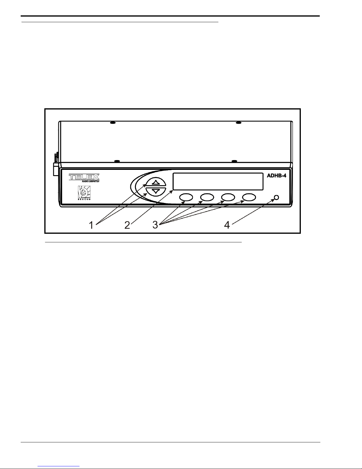
Front Panel Controls and Indicators
1. Volume Buttons - The Volume buttons are used to adjust the volume to the controller (internal) headset connection
and selecting options while in the front panel’s soft menu.
2. Color Display - The color display gives the user graphical indications of events as they occur in either normal
operation mode or in programming mode.
3. Softkeys (4) - The Softkeys are used to enter programming mode and interact with the soft menus.
4. Front LED Indicator - The Front LED indicates power to the unit is on if green; a PTT event is occurring if red.
FIGURE 1. ADHB-4 Front Panel Controls and Indicators
16
Page 17

Introduction
Back Plane Connections
1. USB Port - The USB Port is used to connect the ADHB-4 to a computer.
2. 10/100 NETWORK Port - The 10/100 NETWORK port is used to connect the ADHB-4 to an IP Network with a
standard RJ-45 Ethernet interface cable. The Ethernet port connector supports a Base 10/100 Cat 5E connection.
3. NENA Jack - The NENA (National Emergency Number Association) jack is used to connect an RJ-12 NENA
phone.
4. PHONE Jack - The PHONE Jack is used to connect a phone handset supplied with a mini RJ 4-pin connector.
5. FOOTSWITCH Jack - The FOOTSWITCH jack is used to connect a footswitch and supports two inputs: PTT and
monitor.
6. ACCESSORY Port - The ACCESSORY port supports a DB-15 to provide access to miscellaneous functionality.
7. REMOTE HEADSET Ports (1 and 2) - The REMOTE HEADSET ports (1 and 2) are used to connect an optional
RHB (Remote Headset Box) using the DB-9 cable supplied with the RHB unit. Up to two (2) RHBs can be
connected.
8. DESKMIC Jack (RJ11) - The DESKMIC jack is used to connect an RJ-11–fitted electret or dynamic microphone.
9. SPEAKER 1–2, 3–4, 5–6 Jacks - Each SPEAKER jack is used to connect a speaker pair . These three (3) receptacles
are equipped with 3.5mm stereo jacks requiring self-powered, amplified PC type speakers.
10. POWER Jack - The POWER jack is used to connect a 2.5mm center positive plug supplied by 12 to 16VDC power.
FIGURE 2. ADHB-4 Back Plane Connections
Side Panel Connections
1. MIC (XLR) Connector - The MIC connector is used to connect a 3-pin XLR dynamic microphone. PTT is initiated
from C-Soft or a footswitch.
2. POWER LED Indicator - The LED indicates phantom power is supplied to the XLR jack when lit.
3. HEADSET Jack - The HEADSET jack is used to connect a headset with dual channel 1/4” plugs.
4. Polarity Hash Marks.- Polarity Hash Marks are provided on the side of the unit to indicate headset connector
orientation.
FIGURE 3. ADHB-4 Side Panel Connections
17
Page 18

Specifications
Specifications
Power Requirements:
+12VDC to +16VDC, semi-regulated, 1.25A.
Audio Distortion:
2% THD maximum
Frequency Response:
±
1.5dB, 300 to 3000Hz
NENA Input/Output Impedance:
600 Ohms nominal
Relay Contact Ratings:
1A 125VAC—Form C Contacts
Ethernet Speed:
10/100 BaseT
USB:
Version 2.0
Storage Conditions:
Temperature: 28.8° to 48.8° C (-20° to 120° F)
Humidity: 100% Non-Condensing
Operating Conditions:
Temperature: 0° to 55° C (32° to 131°F)
Humidity: 100% Non-Condensing
Altitude: -500 to 13000 ft.
Dimensions:
50.8mm H x 209.5mm D x 279.4mm W (2” H x 8.25” D x 11” W)
Weight:
3.6 lbs (unit), 6 lbs (shipping weight)
18
Page 19

CHAPTER 2
Installation
WARNING: Do not open the unit. No user-serviceable parts are contained within. Bosch cannot be responsible for
damage. If the unit is opened, the warranty can be voided. For troubleshooting steps contact the technical
support center. See “Phone Numbers” on page 2 for contact information.
Installation
REFERENCE: The installation process requires you to reference both this manual and the C-Soft Software Console
Administrator’s Guide (P/N LIT000082000) which is available on the CD that ships with the ADHB-4 or
can be downloaded at www.Telex.com/Downloads/.
To Install your ADHB-4:
Step 1 Determine where to mount your ADHB-4.
Step 2 Determine if an RHB is required for your system. See “Remote Headset Box” on page 73.
Step 3 Connect hardware to the ADHB-4. See “Connect ADHB-4 Hardware” on page 27.
Step 4 Install the current version of C-Soft. For more information. See the C-Soft Software Console
Administrator’s Guide (P/N LIT000082000).
Step 5 If using Windows 7 OS, install the ADHB-4 driver. See “Install the ADHB-4 Driver with Windows 7” on
page 28.
Step 6 Connect the ADHB-4 to power. “Apply Power to the ADHB-4” on page 34.
Step 7 Connect the ADHB-4 to the PC. “Connect the USB Cable” on page 34.
Step 8 If using Windows XP OS, install the ADHB-4 driver. See “Install the ADHB-4 Driver with Windows XP”
on page 30.
Step 9 Set up the ADHB-4 using the web browser configuration windows. See “Configuration” on page 35.
Step 10 Set up C-Soft parameters. See the C-Soft Software Console Administrator’s Guide
(P/N LIT000082000).
CAUTION: Do not apply power to the unit until step 6. Failure to heed this caution will result in damage to the unit. Bosch is
not responsible for damage caused when power is applied before the installation process is complete and the
warranty can be voided.
19
Page 20

ADHB-4 Mounting
ADHB-4 Mounting
Mounting
The ADHB-4 is mounted on or under a surface such as a desk by either placing it on the work surface or using mounting
brackets to fix it in place.
• Ensure there is enough clearance for back and side panel connections.
• Provide space for at least one (1) speaker pair.
NOTE: A dispatch monitor, weighing up to 35 lbs. maximum, can be placed on top of the unit.
ADHB-4 Mounting Brackets
The ADHB-4 can be mounted on the underside or topside of the surface using optional ADHB-4 mounting brackets. For part
number information, see “Optional Hardware” on page 14.
Underside Mounting
To install the ADHB-4 on the desk underside, do the following:
1. Remove the top screws (B), from the sides of the ADHB-4.
2. Using the screws removed in step 1, attach the brackets (A) to the sides of the ADHB-4 as shown in Figure 4.
3. Hold the ADHB-4 in the desired mounting position.
4. Using a pencil, mark hole positions on the mounting surface.
5. Drill holes to accept a #4-40 x 1/4” screw (C).
6. Using the screws (C) supplied with the bracket, attach the ADHB-4 to the mounting surface.
FIGURE 4. ADHB-4 Underside Mounting
20
Page 21

Topside Mounting
To install the ADHB-4 on the desk topside, do the following:
1. Remove the top screws (F) from the sides of the ADHB-4.
2. Using the screws removed in step 1, attach the brackets (D) to the sides of the ADHB-4, as shown in Figure 5.
3. Place the ADHB-4 in the desired mounting position.
4. Using a pencil, mark hole positions on the mounting surface.
5. Drill holes to accept a #4-40 x 1/4” screw (E).
6. Using the screws (E) supplied with the bracket, attach the ADHB-4 to the mounting surface.
Installation
FIGURE 5. ADHB-4 Topside Mounting
21
Page 22

ADHB-4 Connections
ADHB-4 Connections
USB Port
The USB port is used to connect the ADHB-4 directly to a PC. The USB connection is required to send the audio and control
data between C-Soft and the ADHB-4.
IMPORTANT : If it is necessary to disconnect the USB from the computer or ADHB-4, the USB device should be
safely removed.
To safely disconnect the USB from the computer, do the following:
1. Close the C-Soft console.
2. Safely remove hardware.
REFERENCE:For more information, see your operating system user manual.
3. Disconnect the USB from the computer and ADHB-4.
10/100 NETWORK Port
The NETWORK port is used to connect an Ethernet cable to the ADHB-4.
PHONE Jack
The PHONE jack is used to connect a POTS (Plain Old telephone Service) handset, fitted with a mini RJ 4-pin-connector, to
the ADHB-4. This jack can also be used to connect to a phone system.
To connect to a phone system, do the following:
1. Remove the handset from the phone (at the handset side of the wire) leaving the wire connected to the main phone.
2. Connect the line directly to the phone jack.
NENA Jack
The NENA jack is used to connect a NENA phone with an RJ-12 connector, to the ADHB-4 allowing full duplex
conversation. NENA operation is only permitted when headset(s) are selected and detected for use at the dispatch position.The
offhook condition is triggered by a contact closure that is part of the NENA jack wiring.
The NENA connector wiring diagram is shown in Figure 6. Pin out s for the RJ-12 connector are shown in Figure 7.
FIGURE 6. NENA Phone Connector
22
Page 23

Installation
NENA Phone Connector
The NENA Phone connector description:
• ADHB-4 connects to NENA from the RJ-12 connector.
• Balanced 600 Ohm audio in and out to eliminate ground loops.
• Telephone RX audio routed to headset for entire offhook duration.
• Radio RX audio routes to console when telephone goes offhook.
• The hook switch input is diode protected from voltages above 5VDC.
RJ-12 Connector
An RJ-12 connector provides input/output for a NENA port. When the NENA is taken offhook, the input transitions from high
to low and NENA RX audio is routed to the active handset or headset’s earpiece while NENA TX is routed from the active
handset or headset’s microphone.
NOTE: A headset or handset is required for NENA use. A desk mic cannot be used on a NENA.
FIGURE 7. RJ-12 Pin Outs—NENA phone
FOOTSWITCH Jack
The FOOTSWITCH jack accepts a 3-pin connector that has one (1) or two (2) footswitches connected to it. The input for
PTT uses pins 1 and 2. The input for monitor uses pins 2 and 3. The PTT footswitch can control the PTT functions for the
headset, RHB 1 or 2, or the desk mic depending on the configuration.
3-Pin Connector
FIGURE 8. 3-Pin Connector Pin Outs—Footswitch
23
Page 24

ADHB-4 Connections
ACCESSORY Port
The ACCESSORY port is used to connect optional equipment, to the ADHB-4.
The ADHB-4 accessory port provides two (2) balanced recorder outputs designed with 600 Ohms impedance. The common
recorder output sums and amplifies all common audio to a balanced output for single position capability.
NOTE: Version 1.00 does not support recording audio routed to speakers 3–6.
AUX TTL Level Inputs
The AUX 1 and AUX 2 connections detect a contact closure and sends the information to the C-Soft application. Each
input is diode protected from voltages above +5VDC.
These inputs are:
• DC Isolated
• Diode Protected
• Active Hi/Low (configured in C-Soft)
Form C Relay Contacts
The ADHB-4 provides two (2) Form C relay contacts for general use. Each relay is (separately) controlled from C-Soft. A
1Amp resettable fuse protects both sets of contacts.
DB-15 Connector
TABLE 1. DB-15 Pin Outs—Accessory Port
Pin Number Signal Pin Number Signal
1 AUX 1 Input 9 AUX 2 Input
2 ISO GND 10 ISO GND
3 Analog GND 11 Relay 1 N. C.
4 Relay 1 N. O. 12 Relay 1 Common
5 Common Recorder Out + 13 Relay 2 N. C.
6 Common Recorder Out - 14 Relay 2 N. O.
7 Unsel Recorder Out + 15 Relay 2 Common
8 Unsel Recorder Out -
24
Page 25

Installation
REMOTE HEADSET (1 and 2) Connectors
The REMOTE HEADSET (1 and 2) connectors are used to connect RHB’s. The RHB ships with a
DB-9 (male) to DB-9 (female) cable. Pin outs are shown in Table 2 on page 25.
NOTE: For more information, see “Remote Headset Box” on page 73.
TABLE 2. DB-9 Pin Outs
Pin Number Signal Pin Number Signal
1 Headset Ear GND/Unselect 6 Headset PTT
2 GND 7 +12VDC
3 GND 8 LED Control
4 Headset Ear 9 Open
5 Headset Microphone
DESK MIC Jack
The DESK MIC jack is used to connect an electret or dynamic desk mic with an RJ-11 connector , to the ADHB-4. The RJ-11
modular jack is designed specifically for Bosch microphone models: MD2000 (electret element) or model 6513 (dynamic
element); however, any microphone conforming to the input amplifier specifications may be wired for use.
If an electret microphone is used, a DC bias is placed on the microphone connection to power the microphone.
The nominal audio input levels are 500mv P-P for an electret and or 10-20mv P-P for a dynamic element.
RJ11 Connector
FIGURE 9. RJ-11 Pin Outs—Desk Mic Jack
MIC (XLR) Connector
The MIC (XLR) connector, on the side panel, is used to connect a 3-pin XLR-fitted microphone to the ADHB-4. The XLR
microphone input stage is designed for any standard balanced low impedance dynamic microphone.
A phantom power supply of +48VDC is available for microphones that require power. The +DC is equally applied to pins 2
and 3 of the connector with reference to pin 1 (ground). Phantom power to the XLR jack is set in the configuration windows.
This type of connector does not provide PTT. PTT must be initiated from either C-Soft or a footswitch.
The nominal input level is 10-20mv P-P.
25
Page 26

ADHB-4 Connections
SPEAKERS Jacks (1–2, 3–4, 5–6)
The SPEAKERS jacks are used to connect self-powered 8 Ohm computer speaker pairs to the ADHB-4.
Speaker default settings:
Speaker 1 is dedicated to Select audio.
• If any headset is detected at this console position, Select audio is routed to the headsets and not speaker 1.
• C-Soft provides the ability to set the audio to route to speaker 1 instead of the headset.
• If a desk mic is selected for use and no headset is present, Select audio is routed to Speaker 1.
Speaker 2 is dedicated to Unselect audio. When an active PTT occurs, speaker 2 is always muted.
Speakers 3–6 (positional speakers) are used to monitor Unselect audio.
• C-Soft provides the ability to route a single or multiple Unselect audio stream from a C-Soft line(s) to the
speakers.
• These speakers are not recorded.
REFERENCE: For more information, see the C-Soft Software Console Administrator’s Guide (P/N LIT000082000).
POWER Jack
The POWER jack is used to connect power to the unit. The power requirements are 12VDC to 16VDC, 500mA.
HEADSET Jack
The HEASDSET jack on the side panel is used to connect a 6-wire headset fitted with a dual 1/4” phone plug.
26
Page 27

Connect ADHB-4 Hardware
To make hardware connections to the ADHB-4, do the following:
1. Connect the 10/100 Network cable to the IP Network and the ADHB-4.
2. Connect a speaker pair to the SPEAKER 1–2 jack.
3. Connect an RJ-11 desk mic to the DESKMIC jack.
OR
Connect an XLR desk mic to the XLR jack on the side panel.
OR
Connect, matching polarity hash marks with headset connector grooves, a dual 1/4” headset connector to the
HEADSET jack, to the connector on the side panel.
4. Connect optional audio devices:
• NENA to the NENA jack.
• Footswitch to the FOOTSWITCH jack.
• Recorder/accessory to the ACCESSORY port.
• Speaker pair(s) to the SPEAKER 3–4, or 5–6 jack.
• Install RHB(s) to the REMOTE HEADSET 1 and/or 2 ports.
NOTE: For more information, see “RHB Installation” on page 75.
Installation
5. Ensure power is supplied to the speaker pair(s).
6. Ensure the speaker volume and headset volume are turned to an audible level.
IMPORTANT:
• Do not connect the ADHB-4 to power until after C-Soft installation.
• Do not connect the USB cable to the PC until after C-Soft Installation.
C-Soft Installation
The C-Soft installation is described in the C-Soft Software Console Administrator’s Guide (P/N LIT000082000) available on
the CD that ships with the ADHB-4 or can be downloaded at www.Telex.com/Downloads/.
IMPORTANT: Before C-Soft installation, ensure the USB is not connected to the ADHB-4.
ADHB-4 Driver Installation
The ADHB-4 Driver installation process begins after a USB connection to the PC is established. Since the installation
requires access to the usb_drivers folder, which is included in the C-Soft installation folder, C-Soft must be installed before the
ADHB-4 driver.
• PCs running Windows XP install C-Soft and the ADHB-4 driver separately. See “Install the ADHB-4 Driver
with Windows 7” on page 28.
• PCs running Windows 7 install the ADHB-4 driver right after C-Soft is installed. See “Install the ADHB-4
Driver with Windows 7” on page 28.
27
Page 28

ADHB-4 Driver Installation
Install the ADHB-4 Driver with Windows 7
The Windows 7 driver installation wizard appears right after installing the new version of C-Soft.
To install ADHB-4 driver on PCs running Windows 7, do the following:
1. From the ADHB-4 installation wizard Welcome window, click Next.
FIGURE 10. Found New Hardware Wizard—Welcome
2. From the Windows Security window, click Install.
FIGURE 11. Windows Security Message
28
Page 29

From the Congratulations window, click Finish.
3.
Installation
FIGURE 12. Congratulations! Window
29
Page 30

ADHB-4 Driver Installation
Install the ADHB-4 Driver with Windows XP
Once the ADHB-4 hardware connections, including the USB connection to the PC, are complete the Found New Hardware
wizard appears.
To install the ADHB-4 Driver with Windows XP, do the following:
NOTE: The wizard appears when a USB connection from the ADHB-4 to the PC is established. If necessary, the
USB connection can be unplugged and replugged to reopen the driver installation wizard.
1. Ensure the current version of C-Soft is installed on the PC.
1. From the wizard’s Welcome window, select the No, not this time radio but to n
2. Click Next.
30
FIGURE 13. Found New Hardware Wizard—Welcome
Page 31

From the This wizard helps you install software for: ADHB-4 window, select the Install from a list or specific
3.
location (Advanced) radio button.
4. Click Next.
Installation
FIGURE 14. This wizard helps you install the software for: ADHB-4 Window
31
Page 32

ADHB-4 Driver Installation
5.
From the Please choose your search and installation options window, select the Include this location in the search
check box.
FIGURE 15. Please choose your search and installation options Window
6. Click Browse.
7. From the Browse For Folder window, select C:\Program Files|Telex
Communications|CSoft|usb_drivers|Winusb_XP.
NOTE: If this folder is not available you need to install the current version of C-Soft.
32
Page 33

Click OK.
8.
Installation
FIGURE 16. Browse for Folder Window
9. From the Hardware Installation window, click Continue Anyway.
The wizard takes a few minutes to install the software.
FIGURE 17. Hardware Installation Window
33
Page 34

ADHB-4 Driver Installation
10.
From the Completing the Found New Hardware Wizard, click Finish.
The Wizard closes and the ADHB-4 driver is installed.
FIGURE 18. Completing the Found New Hardware Wizard
Apply Power to the ADHB-4
Power can now be safely applied to the ADHB-4.
To apply power, do the following.
> Connect power to the ADHB-4.
The system information appears momentarily, then normal operation mode appears.
Connect the USB Cable
The ADHB-4 can now be connected to the PC.
To connect the USB cable, do the following:
> Connect one end of the provided USB cable to a PC and the other end to the ADHB-4.
USB displays in the upper right corner to indicate a connection to a PC
34
Page 35

CHAPTER 3
Configuration
Web Browser Configuration
The ADHB-4 uses a web browser to configure the device. The position name, firmware version, and links are visible from
every configuration window.
NOTE: The second level navigation links can be used to collapse the view to display individual sections at a time.
FIGURE 19. Second Level Navigation Links
35
Page 36

Home Link
Home Link
The Home link, located in the left navigation pane, is used to open the Home window. The Home window contains a
description and contact information.
FIGURE 20. Home Window
36
Page 37

Account Management Window
The Account Management window, see Figure 21, is used to change the administrator’s account password.
Configuration
FIGURE 21. Account Management Window
CHANGE PASSWORD
Username Field
The Username field displays admin, which is the default and only username allowed for the ADHB-4 account. This field is
grayed-out to indicate it cannot be changed.
Password Field
The Password field is used to enter the current admin password.
This field can contain up to 16 characters.
New Password Field
The New Password field is used to enter a new password.
This field can contain up to 16 alphanumeric characters.
37
Page 38

Account Management Window
Confirm Password Field
The Confirm Password field is used to re-enter the new password.
Submit Button
The Submit button is used to submit the new password. Once clicked, the new password is permanently saved.
To change the ADHB-4’s password, do the following:
1. In the Password field, enter the current password.
2. In the New Password field, enter a new password.
3. In the Confirm Password field, re-enter the new password.
4. Click Submit.
The new password is permanently saved. The message, SUCCESS: Your Password has successfully been changed
appears at the top of the window.
FIGURE 22. Password Change Success Message
NOTE: If an error is made, the message: ERROR: Incorrect password, shown in Figure 23 appears.
FIGURE 23. ERROR: Incorrect Password
38
Page 39

Configuration
Ethernet Setup Window
The Ethernet Setup window, shown in Figure 24, is used to configure the ADHB-4’s network parameters. See your network
administer to determine Ethernet Address field values.
FIGURE 24. Ethernet Setup Window
BASE IP SETUP
Use DHCP Check Box
The Use DHCP check box is used to enable the ADHB-4 to automatically obtain the Unit IP Address from the network. Once
selected, all other fields on the window are disabled from use.
The default for this field is, disabled.
NOTE:
• The network must support DHCP if DHCP is used.
• Bosch does not recommend enabling DHCP.
39
Page 40

Ethernet Setup Window
Unit IP Address Field
The Unit IP Address field is used to assign a unique static IP Address to the ADHB-4.
The default IP Address is, 192.168.1.150.
Subnet Mask Field
The Subnet Mask field is used to enter the Subnet Mask Address. The Subnet Mask Address is used to distinguish local
addresses from addresses that require the use of a gateway to reach. A subnet mask is required when configuring the system
for a static IP Address.
The default for this field is, 255.255.0.0.
Default Gateway Field
The Default Gateway field is used to enter the Gateway Address. The Gateway Address is the IP Address for the node used to
reach other networks. A Gateway Address is required when configuring the system for a static IP Address.
The default for this field is, 192.168.1.1.
DNS Address 1–3 Fields
The DNS Address 1–3 fields are used to enter the DNS (Domain Name System) Addresses. This Address points to the DNS
server on your network. See your network administrator for these values.
The default for this field is, 0.0.0.0.
To set up ADHB-4 Ethernet IP, do the following:
NOTE: Contact your network administrator for required values.
1. In the Unit IP Address field, enter the IP Address for the ADHB-4.
2. In the Subnet Mask field, enter the Subnet Mask for the network.
3. In the Default Gateway field, enter the Gateway IP Address of the network node.
4. In the DNS 1–3 fields, enter DNS Addresse(s).
5. Click Submit.
6. From the left navigation pane, click the Save Parameters link.
7. Click Save Parameters.
The configuration is saved to the ADHB-4.
TELEX SYSTEM MANAGER SETUP
System Manager Enable Check Box
The System Manager Enable check box is used to enable communication between the ADHB-4 and TSM (Telex System
Manager). TSM provides a centralized location to configure Telex Radio Dispatch solutions. The ADHB-4 firmware is
updated with TSM.
To enable communication between ADHB-4 and TSM, do the following:
> From the Ethernet Setup window, select the System Manager Enable check box.
Communication between the ADHB-4 and TSM is enabled.
REFERENCE: For more information, see the Telex System Manager Technical Manual (P/N LIT000259000), available for
download at www.telex.com./Downloads/.
40
Page 41

Configuration
System Manager Multicast Address Field
The System Manager Multicast Address field displays the Multicast Address for TSM.
System Manager Incoming Port Field
The System Manager Incoming Port field displays TSM’s incoming port number.
System Manager Outgoing Port Field
The System Manager Outgoing Port field displays TSM’s outgoing port number.
System Manager TTL Field
The System Manger TTL field is used to set the number of routers the multicast packets are allowed to pass through before
being discarded.
The range for this field is, 1 to 6.
The default for this field is, 6.
MISC INFO
MAC Address Field
The MAC Address field displays the ADHB-4’s MAC address. This field is for information only and is not editable.
Serial Number Field
The Serial Number field displays the ADHB-4’s Serial Number. This field is for information only and is not editable.
NOTE: The serial number can also be found on the label attached to the bottom of the ADHB-4.
Kernel Version Field
The Kernel Version field displays the ADHB-4 Software Kernel version. This field is for information only and is not editable.
Submit Button
The Submit button is used to submit changes made to the Ethernet Setup window. Once clicked, the parameters are
temporarily saved.
NOTE: The Save Parameters button must be clicked to permanently save the new configuration to the unit.
To permanently save parameters, do the following:
1. From the left navigation pane, click Save Parameters.
The Save Parameters window opens.
2. Click Save Parameters.
The configuration is saved to the ADHB-4.
41
Page 42

Gain Setup Window
Gain Setup Window
The Gain Setup window, shown in Figure 25, is used to configure audio inputs and outputs.
NOTE: Each option on this page is adjusted with a slider.
To adjust the gain sliders, do the following:
> Use either a mouse or keyboard arrow keys to move the slider in 0.5dB increments to the desired level.
FIGURE 25. Gain Setup Window
MICROPHONE INPUT GAINS
When a microphone input gain slider is moved, it increments by 0.5db. However, once the settings are saved, negative settings
increment by 1.5dB.
EXAMPLE: If the RJ11 slider is set to -1dB and submit is clicked, a success message appears and the RJ-11 is set to
-1.5dB.
RJ11 Desk Mic Slider
The RJ11 Desk Mic slider is used to configure the input level for an RJ-11 desk mic.
The range for this field is -12dB to 10dB.
42
Page 43

Headset Mic Slider
The Headset Mic slider is used to configure the input level for a headset mic.
The range for this field is -12dB to 10dB.
XLR Desk Mic Slider
The XLR Desk Mic slider is used to configure the input level for an XLR headset mic.
The range for this field is -12dB to 10dB.
NENA GAINS
NENA Input Slider
The NENA Input slider is used to configure the input level for a NENA phone.
The range for this field is -30dB to 9dB.
NENA Output Slider
Configuration
The NENA Output slider is used to configure the output level for a NENA phone.
The range for this field is -30dB to 9dB.
RECORDER OUTPUT GAINS
Common Record Vol Slider
The Common Record Vol slider is used to configure the volume gain for the common recorder. The common recorder output
is a summation of any active audio in the dispatch position. Common audio sources include: Select, Unselect (optional),
microphone, NENA TX (included with microphone), and NENA RX.
The range for this field is -20dB to 9dB.
Unselect Record Vol Slide r
The Unselect Record Vol slider is used to configure the volum e gain for the Unselect recorder. This recorder output is
Unselect audio transmitted from C-Soft to the ADHB-4.
The range for this field is -20dB to 9dB.
NOTE: Unselect audio can be configured for inclusion in the common recorder output if desired. See “Common Record
Unsel Check Box” on page 52.
43
Page 44

System Setup Window
Submit Button
The Submit button is used to submit changes made to the Gain Setup window. Once clicked, the new configuration is
temporarily saved.
NOTE: The Save Parameters button must be clicked to permanently save the new configuration to the unit.
To permanently save parameters, do the following:
1. From the left navigation pane, click Save Parameters.
The Save Parameters window opens.
2. Click Save Parameters.
The configuration is saved to the ADHB-4.
System Setup Window
The System Setup window, shown in Figure 26, is used to enable and configure audio resources.
FIGURE 26. System Setup Window—View 1
44
Page 45

Configuration
POSITION NAME SETUP
Name Field
The Name field is used to assign the ADHB-4 unit a user-recognizable name.
This field can contain up to 39 alphanumeric characters.
DESK MIC CONNECTOR SETUP
The Desk Mic Connector Setup section is used to configure the desk mic type and power requirements. A PTT can be
generated from C-Soft or a footswitch for desk mics that require an external PTT.
Mic Connector Drop Down Menu
The Mic Connector drop down menu is used to configure the desk mic connector type. The ADHB-4 supports desk mics with
either an RJ-11 or an XLR connector. Once the ty pe is selected , the Mic type drop down menu options are updated to
correspond with the selected connector type.
Available selections for this field are: RJ11 and XLR.
Mic Type Drop Down Menu
The Mic Type drop down menu is used to configure the desk mic type. The ADHB-4 supports dynamic and electret desk mics.
Dynamic desk mics can come with either an RJ-11 or XLR connector. Electret desk mic are fitted with an RJ-11 type
connector.
Available selections for this field when RJ11 is selected are: Dynamic and Electret.
Available selection for this field when XLR is selected is: Dynamic.
Phantom Power Drop Down Menu
The Phantom Power drop down menu appears when the mic connector type is set to XLR. Use this field to toggle on or off
power supplied to the XLR microphone.
Available selections for this field are: On and Off.
To turn on XLR phantom power, do the following:
1. From the Mic Connector drop down menu, select XLR.
The Phantom Power drop down menu appears. The Mic Type menu defaults to Dynamic.
2. From the Phantom Power drop down menu, select ON.
The red LED on the side of the ADHB-4 indicates power is on.
3. Click Submit.
4. Click the Save Parameters link.
The Save Parameters window appears.
5. Click the Save Parameters button.
The Parameters are saved and the phantom power LED is on.
45
Page 46

System Setup Window
HEADSET SETUP
The Headset Setup section is used to configure headset type and audio channel selection.
RHB 1 Headset Drop Down Menu
The RHB 1 Headset drop down menu is used to configure the headset type used on RHB 1.
NOTE: RHB 1 is connected to the REMOTE HEADSET 1 jack on the back panel.
Available selections for this field are: Mono and Stereo.
RHB 2 Headset Drop Down Menu
The RHB 2 Headset drop down menu is used to configure the headset type used on RHB 2.
Available selections for this field are: Mono and Stereo.
Controller Headset Drop Down Menu
The Controller Headset drop down menu is used to configure the headset type connected to the ADHB-4.
Available selections for this field are: Mono and Stereo.
RHB 1 Audio Drop Down Menu
The RHB 1 Audio drop down menu is used to configure RHB 1 to capture audio originating from the C-Soft’s Select or
Unselect channel. For mono-configured headsets, the audio is limited to Select only. For stereo-configured headsets, the audio
is routed from Select and Unselect.
Available selections for this field are: SEL Audio Only and SEL &UNSEL Audio.
RHB 2 Audio Drop Down Menu
The RHB 2 Audio drop down menu is used to configure RHB 2 to capture audio originating from the C-Soft’s Select or
Unselect channel. For mono-configured headsets, the audio is limited to Select only. For stereo-configured headsets, the audio
is routed from Select and Unselect.
Available selections for this field are: SEL Audio Only and SEL &UNSEL Audio.
Controller Headset Audio Drop Down Menu
The Controller Headset Audio drop down menu is used to configure the ADHB-4 to capture audio originating from C-Soft’s
Select or Unselect channel. For mono-configured headsets, the audio is limited to Select only . For ster eo-configured headsets,
the audio is routed from Select and Unselect.
Available selections for this field are: SEL Audio Only and SEL &UNSEL Audio.
46
Page 47

Configuration
CONSOLE GENERATED PTT
The Console Generated P TT section is used to set up microphone selection when PTT is generated from the console position.
Up to four (4) different microphone sources can be set up for a console generated PT T. When the console operator performs a
PTT from the C-Soft console, the first available microphone source that is not disabled or disconnected, is selected for
transmission in the order set up in this section.
The default for these fields are:
Headset Mic #1
RHB 1 #2
RHB 2 #3
Desk Mic #4
EXAMPLE: When the defaults are set, the audio is routed as follows:
If a headset, and RHB 1, and RHB 2 and desk mic are connected, and a PTT is generated from C-Soft, audio
is routed to the headset’s earpiece.
If an RHB 1, an RHB 2, and a desk mic are connected, and a PTT is generated from C-Soft, audio is routed
to RHB 1.
If an RHB 2 and a desk mic are connected, and a PTT is generated from C-Soft, audi o i s rou t ed to the
RHB 2.
Headset Mic #1–#4 Radio Buttons
The Headset Mic #1–#4 radio button indicates the priority for routing audio through the (controller) headset when a PTT is
generated from C-Soft.
Headset Mic Disable Radio Button
The Headset Mic Disable radio button indicates the headset is ignored when a PTT is generated from C-Soft.
RHB 1 Mic #1–#4 Radio Buttons
The RHB Mic #1–#4 radio button indicates the priority for routing audio through the RHB 1 when a PTT is generated from
C-Soft.
RHB 1 Mic Disable Radio Button
The RHB 1 Mic Disable radio button indicates the RHB 1 is ignored when a PTT is generated from C-Soft.
RHB 2 Mic #1–#4 Radio Buttons
The RHB 2 Mic #1–#4 radio button indicates the priority for routing audio through the RHB 2 when a PTT is generated from
C-Soft.
RHB 2 Mic Disable Radio Button
The RHB 2 Mic Disable radio button indicates the RHB 2 is ignored when a PTT is generated from C-Soft.
Desk Mic #1–#4 Radio Buttons
The Desk Mic #1–#4 radio button indicates the priority for routing audio through the desk mic when a PTT is generated from
C-Soft.
47
Page 48

System Setup Window
Desk Mic Disable Radio Button
The Desk Mic Disable radio button indicates the desk mic is ignored when a PTT is generated from C-Soft.
FOOTSWITCH PTT SETUP
The Footswitch PTT Setup section is used to set up microphone selection when a PTT is generated from a footswitch
connected to the ADHB-4. Up to four (4) different microphone sources can be set up for a footswitch generated PTT. When
the console operator presses the footswitch, the first available microphone source, that is not disabled or disconnected, is
selected for transmission in the order setup in this section.
The default for these fields are:
Headset Mic #1
RHB 1 #2
RHB 2 #3
Desk Mic #4
EXAMPLE: When the defaults are set, the audio is routed as follows:
If a headset, an RHB 1, an RHB 2 and desk mic are connected, and a PTT is generated from the footswitch,
audio is routed to the headset’s earpiece.
If an RHB 1, an RHB 2, and a desk mic are connected, and a PTT is generated from the footswitch, audio is
routed to RHB 1.
If an RHB 2 and a desk mic are connected, and a PTT is generated from the footswitch, audio is routed to the
RHB 2.
Headset Mic #1–#4 Radio Buttons
The Headset Mic #1–#4 radio buttons indicate the priority for rou ting audio through the headset when a footswitch PTT is
generated.
Headset Mic Disable Radio Button
The Headset Mic Disable radio button indicates the headset is ignored when a footswitch PTT is generated.
RHB 1 Mic #1–#4 Radio Buttons
The RHB 1 Mic #1–#4 radio buttons indicate the priority for routing audio through the RHB 1 when a footswitch PTT is
generated.
RHB 1 Mic Disable Radio Button
The RHB 1 Mic Disable radio button indicates the RHB 1 is ignored when a footswitch PTT is generated.
RHB 2 Mic #1–#4 Radio Buttons
The RHB 2 Mix #1–#4 radio buttons indicate the priority for routing audio through the RHB 2 when a footswitch PTT is
generated.
RHB 2 Mic Disable Radio Button
The RHB 2 Mic Disable radio button indicates the RHB 2 is ignored when a footswitch PTT is generated.
48
Page 49

Configuration
Desk Mic #1–#4 Radio Buttons
The Desk Mic #1–#4 radio buttons indicate the priority for routing audio through the desk mic when a footswitch PTT is
generated.
Desk Mic Disable Radio Button
The Desk Mic Disable radio button indicates the desk mic is ignored when a footswitch PTT is generated.
FIGURE 27. System Setup Window—View 2
49
Page 50

System Setup Window
NENA/PHONE MIC SOURCE SETUP
The NENA/PHONE MIC SOURCE SETUP section is used to configure microphone source priorities when a
NENA/phone is active on the ADHB-4. Up to three (3) different microphone sources can be set up when a
NENA/phone is connected and onhook. Once the NENA/phone is taken offhook (low), the ADHB-4 transmits full-duplex
audio to the NENA/phone.
NOTE: A NENA/phone cannot operate without headsets selected that are configured for use at the console position.
The default for these fields is:
Headset Mic #1
RHB 1 #2
RHB 2 #3
EXAMPLE: When the defaults are sets the audio is routed as follows:
If a headset, an RHB 1, and an RHB 2 connected, and the NENA/Phone is taken offhook, audio is routed to
the headset’s earpiece.
If an RHB 1 and an RHB 2 are connected, and the NENA/phone is taken offhook, audio is routed to the
RHB 1.
If an RHB 2 is connected, and the NENA/phone is taken offhook, audio is routed to the RHB 2.
Headset Mic #1–#4 Radio Buttons
The Headset Mic #1–#4 radio buttons indicate the priority for routing audio through the headset when the headset generates a
PTT while the NENA is offhook.
Headset Mic Disable Radio Button
The Headset Mic Disable radio button indicates the headset is disabled from routing audio when the NENA is offhook.
RHB 1 Mic #1–#4 Radio Buttons
The RHB 1 Mic #1–#4 radio buttons indicate the priority for routing audio through RHB 1 when RHB 1’s headset generates a
PTT while the NENA is offhook.
RHB 1 Mic Disable Radio Button
The RHB 1 Mic Disable radio button indicates the RHB 1 is disabled from routing audio when the NENA is offhook.
RHB 2 Mic #1–#4 Radio Buttons
The RHB 2 Mic #1–#4 radio buttons indicate the priority for routing audio through the RHB 2 when RHB 2’s headset
generates a PTT while the NENA is offhook.
RHB 2 Mic Disable Radio Button
The RHB 2 Mic Disable radio button indicates the RHB 2 is disabled from routing audio when the NENA is offhook.
50
Page 51

Configuration
PTT PRIORITY SETUP
The PTT Priority Setup section is used to set up the priorities of different PTT sources from the ADHB-4. The highest
priority is #1, the lowest is #6.
Console Generated PTT Radio Button
The Console Generated PTT radio button is, by default, always set to #1 priority. This setting cannot be changed.
EXAMPLE: When the PTT priority is set up as follows:
Console Generated PTT #1
Headset P TT #2
RHB 1 PTT #3
RHB 2 PTT No priority
Desk Mic P TT #4
If a PTT is generated from the headset, and RHB 1 is currently engaged in a PTT event, the headset takes
control from RHB 1.
If a PTT is generated from RHB 1 while the headset is currently engaged in a PTT event, RHB 1 is ignored.
If a PTT is generated from RHB 1 while the desk mic is engaged in a PTT event, the RHB 1 takes control
from the desk mic.
Headset PTT #1–#6 Radio Buttons
The Headset PTT #1–#6 radio buttons indicate the priority for routing audio to the headset.
Headset PTT No Priority Radio Button
The Headset PTT No Priority radio button indicates audio is routed to the headset mic on a, first come first serve basis.
The Headset PTT default is: No Priority.
RHB 1 PTT #1–#6 Radio Buttons
The RHB 1 PTT #1–#6 radio buttons indicate the priority for routing audio to the RHB 1.
RHB 1 PTT No Priority Radio Button
The RHB 1 PTT No Priority radio button indicates audio is routed to the RHB 1 on a, first come first serve basis.
The RHB 1 PTT default is, No Priority.
RHB 2 PTT #1–#6 Radio Buttons
The RHB 2 PTT #1–#6 radio buttons indicate the priority for routing audio to the RHB 2.
RHB 2 PTT No Priority Radio Button
The RHB 2 PTT No Priority radio button indicates audio is routed to the RHB 2 on a, first come first serve basis.
The RHB 2 PTT default is No Priority.
Desk Mic PTT #1–#6 Radio Buttons
The Desk PTT #1–#6 radio buttons indicate the priority for routing audio to the Desk Mic.
51
Page 52

System Setup Window
Desk Mic PTT No Priority Radio Button
The Desk PTT No Priority radio button indicates audio is routed to the Deck Mic on a, first come first serve basis.
The Desk Mic PTT default is No Priority.
Footswitch PTT #1–#6 Radio Buttons
The Footswitch PTT #1–#6 radio buttons indicate the priority for routing audio when the footswitch is activated.
Footswitch PTT No Priority Radio Button
Footswitch PTT No Priority radio button indicates audio is routed on a, first come first serve basis when the footswitch is
activated
Console Generated PTT #1–#6 Radio Button
The Console Generated PTT #1–#6 radio buttons indicate a console generated PTT is, by default, first priority and audio is
routed to the device configured for the console PTT.
NOTE: This radio button cannot be changed.
SYSTEM PARAMETERS SETUP
LCD Backlight Field
The LCD Backlight field is used to adjust the display’s backlight brightness. The brightness can also be adjusted using the
Backlight softkey on the front panel.
The range for this field is 1 to 10.
The default for this field is 5.
To change the backlight brightness, do the following:
1. From the System Setup window, enter a value from 1 (darkest) to 10 (brightest) in the LCD Backlight field.
2. Click Submit.
The setting takes affect and the display changes accordingly.
Change IP On Display Check Box
The Change IP On Display check box indicates the IP Address can be changed using the softkeys on the front of the unit.
Common Record Unsel Check Box
The Common Record Unsel check box indicates the Unselect audio is included in the common recorder audio.
Submit Button
The Submit button is used to submit changes made to the System Setup window. Once clicked, the new configuration is
temporarily saved.
NOTE: The Save Parameters button must be clicked to permanently save the new configuration to the unit.
52
Page 53

Configuration
To permanently save parameters, do the following:
1. From the left navigation pane, click Save Parameters.
The Save Parameters window opens.
2. Click Save Parameters.
The configuration is saved to the ADHB-4.
System Status
The System Status window, shown in Figure 28, summarizes the current ADHB-4 system setup and activity. From this
window, you can view the status of the auxiliary relays, gain levels, connected microphones, and speakers as well as monitor
PTT statuses.
FIGURE 28. System Status Window
Refresh Status Link
The Refresh Status link, located in the left navigation pane, is used to refresh the information in the System Status window.
NOTE: This link is a manual refresh. The statuses in this window automatically update when changes occur.
53
Page 54

System Status
AUX/RELAY STATUS
AUX 1 Input
The AUX 1 Input field indicates the current state of the AUX 1 input.
Field values can be: Low or High.
AUX 2 Input
The AUX 2 Input field indicates the current state of the AUX 2 input.
Field values can be: Low or High.
Relay 1 Field
The Relay 1 field indicates the current state of the relay 1.
Field values can be: On or Off.
Relay 2 Field
The Relay 2 field indicates the current state of the relay 2.
Field values can be On or Off.
GAINS STATUS
Mic Level Field
The Mic Level field indicates the input gain level for the currently active PTT for any source.
NENA Level Field
The NENA Level field indicates the input gain level for the NENA which is currently off hook.
54
Page 55

MICROPHONE STATUS
Headset Connection Field
The Headset Connection field indicates the current state of the headset.
Field values can be: Connected or Disconnected.
RHB 1 Connection Field
The RHB 1 Connection field indicates the current state of RHB 1’s connection.
Field values can be: Connected or Disconnected.
RHB 2 Connection Field
The RHB 2 Connection field indicates the current state of RHB 2’s connection.
Field values can be: Connected or Disconnected.
Headset PTT Field
Configuration
The Headset PTT field indicates the current state of the headset’s PTT.
Field values can be: Active or Inactive.
RHB 1 PTT Field
The RHB 1 PTT field indicates the current state of the RHB 1’s PTT.
Field values can be: Active or Inactive.
RHB 2 PTT Field
The RHB 2 PTT field indicates the current state of the RHB 2’s PTT.
Field values can be: Active or Inactive
SPEAKER STATUS
Speakers 1–6 Field
The Speakers 1–6 field indicates if a speaker(s) is connected and whether or not it is active.
Field values can be:
Connected Indicates the speaker is connected but idle.
Disconnected Indicates a speaker is not connected.
Active Indicates the speaker is currently in use.
Muted Indicates the speaker is muted.
Min Muted Indicates the speaker is muted to a minimum (audible level set in C-Soft Designer).
55
Page 56

System Status
MISC STATUS
Desk Mic Monitor Field
The Desk Mic Monitor field indicates the current sate of the desk mic monitor.
Field values can be: Active or Inactive.
Footswitch Monitor Field
The Footswitch Monitor field indicates current state of the footswitch monitor.
Field values can be: Active or Inactive.
NENA Hook Field
The NENA Hook field indicates the current state of the NENA hook.
Field values can be: Active (offhook) or Inactive (onhook).
Desk Mic PTT Field
The Desk Mic PTT field indicates the current state of the Desk Mic PTT activity.
Field values can be: Active or Inactive.
Footswitch PTT Field
The Footswitch PTT field indicates the current state of the Footswitch PTT activity.
Field values can be: Active or Inactive.
56
Page 57

Configuration
Save Parameters
Save Parameters Button
The Save Parameters buttons is used to store all parameters to the ADHB-4’s memory for permanent storage.
NOTE: If the IP Address is changed on the Ethernet Setup window, the web browser is redirected to the new IP Address
after the parameters are saved.
FIGURE 29. Save Parameters Window
Restore Factory Default Button
The Restore Factory Default button is used to restore the configuration to the factory default settings.
To restore factory defaults, do the following:
1. Click the Restore Factory Default button.
The parameters are restored to the factory defaults.
2. Click the Save Parameters button.
The factory defaults parameters are permanently saved to the ADHB-4.
NOTE: If the restore Factory Default button is clicked in error, the previous configuration can be retrieved by clicking
the Reset button.
57
Page 58

Save Parameters
Reset ADHB-4 Button
The Reset ADHB-4 button is used to reboot the ADHB-4.
To reset the ADHB-4, do the following:
> Click Reset ADHB-4.
Or
Cycle power to the unit off/on.
58
Page 59

LCD Display
The ADHB-4 uses an LCD display to provide user feedback.
Upon power up, the following ADHB-4 information appears on the display for five (5) seconds:
• NAME: The name assigned when the ADHB-4 is configured on the System Setup window.
• IP: The IP Address of the ADHB-4.
• SN: The serial number of the ADHB-4.
• FW: The currently loaded firmware version.
• KN: The current kernel versi on.
CHAPTER 4
Operation
NOTE: The same information can be viewed by pressing the System Info softkey on the front panel.
Once the power up sequence is complete and the system info screen disappears, the ADHB-4 displays in normal operation
mode, indicating connectivity and activity for the individual audio sources. Pressing a so ft key, changes the display to
programming mode.
Volume Buttons
The Volume buttons are used to control the volume of the controller headset connector. These buttons are sometimes used in
programming mode, as a result, the volume cannot be changed while in programming mode.
Volume Level
The Volume Level indicator displays the current volume, in 10% increments, set for the earpiece on the controller’ s heads et.
The default value for this indicator is 50% volume.
Front LED Indicator
The Front LED indicates power to the unit is on if green; a PTT event is occurring if red
59
Page 60

Normal Operation Mode
Phantom Power LED Indicator
The Phantom Power LED indicates phantom power is supplied to the desk mic connected to the MIC (XLR) connector on
the left panel of the unit when lit.
Normal Operation Mode
While in Normal Operation mode the ADHB-4 displays icons for speakers, auxiliary devices, relay controlled devices, and
NENA appear across the top of the ADHB-4 display. A volume meter, PTT indicator, time, date, and year occupy the middle
of the display. Softkey labels, up to four (4), appear across the bottom.
USB Indicator Icon
The USB Indicator icon indicates there is a USB connection to a PC running C-Soft.
TABLE 3. USB Icon
Icon Status Description
Confirms the ADHB-4 is connected to a PC.
60
Page 61

Operation
Status Icons
The Status icons provide user-feedback about when and what type of audio sources are connected, and if they are active.
NOTE: Speaker volume is controlled from the console position.
Speaker Status Icons
Speaker Status icons indicate speaker’s status and input number.
NOTE: When no speaker icon appears on the display, no speaker is connected.
TABLE 4. Speaker Status Icon Descriptions
Icon Status Description
When the speaker icon is white, the speaker specified by the number on the
icon is connected.
When the speaker icon has a red X to its right, the speaker specified by the
number on the icon is muted.
When the speaker icon is red, the speaker specified by the number on the icon
is min-muted.
For more information, see “Speakers 1–6 Field” on page 55.
When the speaker icon is green, the speaker specified by the number on the
icon is currently playing audio.
AUX Status Icon
The AUX Status icon indicates the auxiliary device’s status and input number.
TABLE 5. Auxiliary Status Icon Descriptions
Icon Status Description
When the auxiliary icon has a green H on the upper right, the state of the
auxiliary device specified by the number on the icon is high.
When the auxiliary icon has a yellow L on the upper right, the state of the
auxiliary device specified by the number on the icon is low.
61
Page 62

Status Icons
Relay Status Icon
The Relay Status icon indicates the relay controlled device specified by the number on the icon is on. If no relay icon appears,
the relay is off.
TABLE 6. Relay Status Icon Descriptions
Icon Status Description
When the Relay icon appears, the relay specified by the number has changed
state.
NENA Status Icon
The NENA Status icon indicates the NENA is offhook.
TABLE 7. NENA Status Icon Description
Icon Status Description
When the NENA icon appears on the display, a NENA is offhook and
transmitting.
Volume Indicator Icon
The Volume Indicator icon indicates the RX level coming out of the controller headset. From the bottom to the top, one (1)
bar is lowest volume and 10 bars is the highest volume. Each increment represent 10% of the total volume. The volume is
controlled with the volume buttons on the front of the ADHB-4.
The default setting is 50%.
TABLE 8. Volume Meter Description
Icon Status Description
When audio plays from the controller headset’ s earpiece, this setting indicates
the total volume.
To change the controller headset volume, do the following:
> From the front panel, press the up volume button.
The volume in the headset increases.
OR
From the front panel, press the down volume button.
The volume in the headset decreases.
62
Page 63

PTT Indicator Icons
The PTT Indicator icons indicate the device that is currently generating a PTT.
TABLE 9. PTT Indicator Icons
Icon Status Description
When a PTT is generated from the controller headset, a TX headset
icon appears on the display.
When a PTT is generated from a desk mic, a TX Desk Mic icon
appears on the display.
When a PTT is generated from a footswitch, a TX Footswitch icon
appears on the display.
Operation
When a PTT is generated from a headset connected RHB 1, a TX
RHB 1 icon appears on the display.
When a PTT is generated from a headset connected to RHB 2, a TX
RHB 2 icon appears on the display.
Programming Mode
Once a softkey is pressed, the ADHB-4 switches to programming mode.
Available selections are: Network, Clock Mode, Backlight, System Info.
Network Menu
The Network menu is used to change the IP Address and the Subnet Mask for the ADHB-4.
NOTE:
• If permission to change the IP Address is disabled, a message To chang e IP or Subnet mask pl ease refer to the
webpage appears on the display.
• For more information, see “Change IP On Display Check Box” on page 52.
63
Page 64

Programming Mode
To change the IP Address from the ADHB-4 front panel, do the following:
1. Press the Network softkey
The Network menu appears, indicating current IP Address and Subnet Mask.
2. Press the IP Address softkey.
The IP Address menu appears with the first quad highlighted red.
3. Use the +10 or -10 softkey to change the quad number by 10.
4. Use the up (plus) or down (minus) buttons to change the quad number by 1.
5. Press the Next Quad softkey to move to the next quad to the right.
6. Ensure the IP Address is entered correctly.
7. Press the Back softkey.
8. Press the Save softkey.
The screen momentarily flashes and the display is back to normal operation mode.
To change the Subnet Mask from the ADHB-4 front panel, do the following:
1. Press the Network softkey
The Network menu appears, indicating current IP Address and Subnet Mask.
2. Press the IP Address softkey.
The IP Address menu appears with the first quad highlighted red.
3. Use the +10 or -10 softkey to change the quad number by 10.
The quad changes by increments of 10.
4. Use the up (plus) or down (minus) buttons to change the quad number by 1.
The quad changes by increments of 1.
5. Press the Next Quad softkey to move to the next quad to the rig ht.
The active quad is highlighted red.
6. Press the Back softkey.
7. Ensure the Subnet Mask is entered correctly.
8. Press the Save softkey.
The screen momentarily flashes, the new Subnet Mask is saved, and the display is restored to normal operation mode.
Clock Mode Menu
The Clock Mode menu is used to change the clock’s display mode. The actual time is read from the PC. The clock does not
appear if the ADHB-4 is disconnected from the computer.
Available selection are: 24 HR (military) or 12 HR (civilian).
To change how the time displays, do the followi ng:
1. Press the Clock Mode softkey.
The clock menu appears indicating the current time mode.
2. Press the 12 HR or 24 HR softkey.
The display changes according to selection.
3. Press the Back softkey.
The time displays in the selected mode after two(2) seconds.
64
Page 65

Operation
Backlight Menu
The Backlight menu is used to adjust the display’s backlight brightness. The brightness level ranges from 1 (darkest) to 10
(brightest). The brightness can also be adjusted using the web browser configuration windows.
To change the backlight brightness, do the following:
1. Press the Backlight softkey.
The backlight menu appears, indicating the current brightness level.
2. Press the + softkey to increase the brightness.
OR
Press the - softkey to reduce the brightness.
3. Press the Back softkey.
The display’s brightness is set and the display is restored to normal operation mode.
System Info Menu
The System Info menu displays the same information as when ADHB-4 powers up. The web browser configuration password
can also be reset in the menu.
NOTE: For more information, see “LCD Display” on page 59.
To display the System Info menu do the following.
1. Press the System Info softkey.
The system information appears on the display.
2. Press the System Info softkey again to return to normal operation mode.
To reset the web browser configuration software password, do the following:
1. Press the System Info softkey.
The System Info menu appears on the display.
2. Press the softkeys in the following sequence:
1, 1, 3, 1, 2, 1, 3.
The message: Reset web password to default? appears on the display.
3. Press the YES softkey to change the password to the system default.
The display changes to normal operation mode and accessing the web browser configuration now requires the
default password.
OR
Press the NO softkey to keep the current password.
The display changes to normal operation mode.
NOTE: The default password is admin.
65
Page 66

C-Soft Controls
C-Soft Controls
Speaker selection and volume controls are accessed from the C-Soft console. ADHB-4 connection indicators appear on the
console status bar.
C-Soft Status Bar
The C-Soft status bar displays ADHB-4 connection indicators. If a status appears, a connection to the device is established.
Available statuses are: ADHB4 and NENA.
FIGURE 30. Console Speaker and Status Indications
Speaker Indications
The Speaker Indications appear on the Select, Phone, Global Call History, IRR, NENA and SIP buttons. The speaker icon,
shown in Figure 30, indicates the speaker number and speaker status.
NOTE: The location of the speaker icons depend on the line’s button size.
Single Speaker Icon
The Single Speaker icon indicates the speaker number audio is transmitting on. This speaker icon is a cyan circle with a black
speaker number in the center.
Common Unselect Speaker Icon
The Common Unselect Speaker icon indicates audio is transmitting to the speaker number shown on the icon and speaker 2
(common unselect). This icon is a cyan square with a red speaker number in the center.
Disconnected Speaker Icon
The Disconnected Speaker icon indicates the speaker configured on the button is not connected. This icon is a single speaker
icon with a red circle-backslash symbol on top.
Muted Speaker Icon
The Muted Speaker icon indicates the line’s speaker is muted. The icon is a red circle-backslash symbol with a white speaker
in the center.
66
Page 67

Operation
Speaker Setup in C-Soft
Initially, the ADHB-4’s speakers are set up, by default, to route selected audio to speaker 1 and route all unselected speaker
audio to speaker 2.
Unselect Audio
Unselect audio can be configured from the console position to route through speakers other than the default. Select audio is
always routed to speaker 1.
One (1) of two (2) methods can be used to change the unselect speaker audio:
• With the Per Line Unselect window, see “Per Line Unselect Window” on page 6 7.
• With the ADHB-4 Global window, see “ADHB-4 Global Window” on page 69.
Per Line Unselect Window
The Per Line Unselect window is accessed by right-clicking the line’ s select button on the console. Once the window appears,
you can choose speaker(s) to route Unselect audio through.
The default for this window is Speaker 1, Unselect, Speakers 2–6 Unselect.
Speaker 2–6 Radio Buttons
The Speaker 2–6 radio buttons are used to set one (1) Unselect positional speaker for the line’s audio.
Positional + Speaker 2 Check Box
The Positional + Speaker 2 check box is used to set one (1) Unselect positional speaker plus speaker 2 for the line’s audio.
This setting also applies to recording unselect audio.
If this check box is selected, a positional speaker (3–6) and speaker 2 are used to play/record audio and the single speaker icon,
shown in Figure 30, appears on the line’s Select button.
If this check box is not selected, speaker 2 is used to play/record audio and the Common Unselect speaker icon, shown in
Figure 30, appears on the line’s Select button.
67
Page 68

Speaker Setup in C-Soft
Set Button
The Set button is used to accept changes and close the window.
FIGURE 31. Per Line Unselect Speaker
NOTE: This window is also accessible through the ADHB-4 Global window. See “Per Line Unselect” on page 70.
To change the per line unselect speaker routing, do the following:
1. From the C-Soft console, right-click the line’s select button.
The Per Line Unselect window appears.
2. Select the radio button(s) you want Unselect audio to be routed to.
3. Click Set.
The settings are saved and the window closes
OR
Click the red X in the upper-right corner to discard changes.
The window closes and the settings are not changed.
68
Page 69

Operation
IRR Speaker Window
The IRR Speaker window is used to select which speakers to record audio for instant recall. Once an Instant Recall button is
right-clicked in C-Soft, the IRR Speaker window appears. See Figure 32.
FIGURE 32. IRR Speaker Window
To change the IRR playback speaker, do the following:
1. From the console, right-click the Instant Recall button.
The IRR Speaker window appears.
2. Select one (1) Speaker 1–6 radio button.
3. Click Set.
The Instant Recall button is configured to playback recordings from the selected speaker when clicked.
ADHB-4 Global Window
The ADHB-4 Global window is used to set up speaker number display mode, and to choose Select/Unselect speaker
configurations.
To open the ADHB-4 Global window, do the following:
> From the console, right-click the status bar.
The ADHB-4 Global window appears.
Button Speaker Numbers Group Box
Button Speaker Numbers On Check Box
The Button Speaker Numbers On check box is used to configure whether or not the speaker numbers assigned to the line
appear on the select buttons. See Figure 33.
69
Page 70

Speaker Setup in C-Soft
Select Speaker Group Box
Always On Radio Button
The Always On radio button indicates audio always plays from the select speaker whether or not the headset is connected.
Audio is also routed to the earpiece if a headset is connected.
Off When Headset Connected Radio Button
The Off When Headset Connected radio button indicates audio is routed only to the headset when connected. Audio plays
from the Select speaker when the headset is disconnected.
Line/Speaker List Group Box
Line Name Column
The Line Name column indicates the user-assigned name for the line.
Unselect Speaker # Column
The Unselect Speaker # column indicates the speaker number used for unselect audio.
FIGURE 33. Select Button Speaker Number Display
Per Line Unselect
The Per Line Unselect window, Figure 31, appears when a line name or unselect speaker number is double-clicked. For
more information, see the “Per Line Unselect Window” on page 67.
70
Page 71

ADHB-4 Volume Control Window
The ADHB-4 Volume Control window is used to adjust the volume or to mute speakers connected to the ADHB-4.
Speaker 3 is muted in the example shown in Figure 34, as indicated by the red circle-backslash symbol.
FIGURE 34. ADHB-4 Speaker Volume Control Window
Operation
To adjust a speaker ’s volume, do the following:
1. Click the Status bar.
The ADHB-4 Volume Control window appears.
2. Move the speaker’s volume slider to the right to increase.volume or left to decrease volume.
The volume meter changes accordingly and the change in volume takes effect immediately.
3. Click the red X in the upper right corner of the window to close the window.
The window closes.
To mute a speaker, do the following:
> Click the speaker icon for the speaker you want to mute.
A red circle-backslash symbol appears on the speaker icon and the speaker no longer plays audio.
71
Page 72

Speaker Setup in C-Soft
72
Page 73

APPENDIX A
Remote Headset Box
Overview
The RHB (Remote Headset Box) is an optional piece of equipment used to expand headset options on the ADHB-4. Each
RHB supports one (1) headset each. Up to two (2) RHBs can be connected to each ADHB-4. The RHB is a plug and play
device; the ADHB-4 recognizes a connection between the two (2) devices, allowing a central location for configuration within
the ADHB-4.
Compatible Headsets
For a list of compatible Telex headsets, see “Optional Hardware” on page 14.
Features
• ADHB-4 provides power to an RHB.
• Dual channel 1/4” headset jack.
• Volume control knob.
• Supports both Select and Unselect in either ear.
• LED for power and PTT indications.
73
Page 74

Controls and Indicators
Controls and Indicators
Front Panel Connections, Controls and Indications
1. Power Indicator LED - The Power indicator LED is green when power is supplied to the unit. It is red when a PTT
is generated with the connected headset. Power is derived from the ADHB-4.
2. Volume Knob - The Volume knob is used to adjust the total volume suppled to the headset’s earpiece.
3. Dual Channel 1/4” Headset Jack - The Dual Channel 1/4” Headset Jack is used to connect a headset to the RHB.
4. Polarity Hash Marks.- Polarity Hash Marks are provided on the front of the unit to indicate headset connector
orientation.
FIGURE 35. RHB Front Panel
Back Panel Connection
1. DB-9 Connector - The DB-9 connector is used to plug the DB-9F end of the supplied cable to the RHB.
FIGURE 36. RHB Back Panel
74
Page 75

Mounting
The RHB can be mounted under the desk or on the desk top. The RHB is fitted with a mounting bracket that can be flipped 180
degrees to change the mounting orientation. The RHB ships with the mounting bracket in position for under-the-desk
mounting. Mounting hardware is included in the RHB shipment.
The RHB ships with the bracket mount assembled for under-the-desk mounting. If you want to mount the RHB on the desk top
the bracket should be flipped 180 degrees.
To change the bracket’s orientation, do the following:
1. Remove th e screws (2 on each side) holding the RHB to the bracket.
2. Slide the RHB out of the bracket.
3. Turn th e bracket 180 degrees.
4. Re-install the screws to reattach the RHB.
5. Slide the RHB back into the bracket.
6. Follow the mounting instructions.
To mount the RHB, do the following:
1. On the mounting surface, mark and drill holes to accept a #10-13 x 3/4” screw or 10-12 x 1” anchor.
2. Attach the RHB to the surface with 4 screws.
The RHB is easily removed from the bracket without having to unmount the bracket.
To remove the RHB from the bracket while mounted, do the following:
1. Disconnect the headset.
2. Disconnect the DB-9 connector from the back of the unit.
3. Remove the screws (2 on each side) holding the RHB to the bracket.
4. Slide the RHB forward.
DB-9 Cable
The DB-9 cable that ships with the RHB is 6ft. long and designed to interface between the RHB and the ADHB-4.
For more information, see “REMOTE HEADSET (1 and 2) Connectors” on page 25.
RHB Installation
To install the RHB , do the following:
NOTE: Install the ADHB-4 before proceeding.
1. Ensure the RHB is mounted. See “Mounting” on page 75.
1. Plug the DB-9 female end of the cable into the TO CONTROL BOX (DB-9) port on the back of the RHB.
2. Plug the DB-9 male end of the cable into a HEADSET (DB-9) port on the back of the ADHB-4.
3. Turn th e volume knob counter-clockwise to lower the volume.
4. Orient the grooves on the headset connector’s housing with the hash marks on the front of the RHB.
5. Insert the plugs in the jacks.
6. Adjust the volume before wearing the headset.
75
Page 76

Configuration
Configuration
The RHB is configured with the ADHB-4 web browser configuration windows.
The following fields are used to configure the RHB:
See “HEADSET SETUP” on page 46.
See “CONSOLE GENERATED PTT” on page 47
See “FOOTSWITCH PTT SETUP” on page 48.
See “NENA/PHONE MIC SOURCE SETUP” on page 50.
See “PTT PRIORITY SETUP” on page 51.
The RHB’s microphone connection status is summarized on the System Status window in the ADHB-4 web browser. See
“MICROPHONE STATUS” on page 55.
76
Page 77

Notes:
77
Page 78

Configuration
78
 Loading...