

Page 1

™
ADAM
DBX
DBX
Dual Bus Expander
Telex Communications, Inc. • 12000 Portland Ave South • Burnsville, MN 55337
9350-7532-000 Rev F, 07/2004
Page 2

ADAM Dual Bus Expander
2
Page 3

ADAM Dual Bus Expander
STOP!!!
You must have REV D of the DBX
backplane!!!
Contact your Sales Representative for
more information.
3
Page 4

ADAM Dual Bus Expander
Proprietary Notice
The RTS product information and design disclosed herein were originated by and are the property of Telex Communications, Inc.. Telex
reserves all patent, proprietary design, manufacturing, reproduction, use and sales rights thereto, and to any article disclosed therein,
except to the extent rights are expressly granted to others.
Copyright Notice
Copyright © 2004 by Telex Communications, Inc. All rights reserved. Reproduction in whole or in part without prior written permission
from Telex is prohibited.
Unpacking and Inspection
Immediately upon receipt of the equipment, inspect the shipping container and the contents carefully for any discrepancies or damage.
Should there be any, notify the freight company and the dealer at once.
This package should include the following:
2- RG-59 Coax Cable 902072750
Plastic Bag 576027-000
4 - Panhead Screws 2.5x10.0 59000-240
1 - Front Card Assembly 90207532-501
1 - Bus Expansion Back Card Assy 90207557-500
1 - DBX User Manual 90357532-000
Warranty Information
RTS products are warranted by Telex Communications, Inc. to be free from defects in the materials and workmanship for a period of
three years from the date of sale.
The sole obligation of Telex during the warranty period is to provide, without charge, parts and labor necessary to remedy covered
defects appearing in products returned prepaid to Telex. This warranty does not cover any defect, malfunction or failure caused beyond
the control of Telex, including unreasonable or negligent operation, abuse, accident, failure to follow instructions in the Service Manual or
the User Manual, defective or improper associated equipment, attempts at modification and repair not authorized by Telex, and shipping
damage. Products with their serial numbers removed or effaced are not covered by this warranty.
To obtain warranty service, follow the procedures entitled “Procedures for Returns” and “Shipping to Manufacturer for Repair or Adjustment”.
This warranty is the sole and exclusive express warranty given with respect to RTS products. It is the responsibility of the user to
determine before purchase that this product is suitable for the user’s intended purpose.
ANY AND ALL IMPLIED WARRANTIES, INCLUDING THE IMPLIED WARRANTY OF MERCHANTABILITY ARE LIMITED TO THE
DURATION OF THIS EXPRESS LIMITED WARRANTY.
NEITHER TELEX NOR THE DEALER WHO SELLS RTS PRODUCTS IS LIABLE FOR INCIDENTAL OR CONSEQUENTIAL DAMAGES OF ANY KIND.
Customer Service
Technical questions should be directed to:
Customer Service Department
RTS/Telex
12000 Portland Avenue South
Burnsville, MN 55337 USA
Telephone: (800) 392-3497
Fax: (800) 323-0498
Return Shipping Instructions
Customer Service Department
Telex Communications, Inc.
Telephone: (800) 392-3497
Fax: (800) 323-0498
Factory Service: (800) 553-5992
Be prepared to provide the company name, address, phone number, contact person regarding the repair, the type and quantity of
equipment , a description of the problem, and the serial number(s).
4
Page 5

ADAM Dual Bus Expander
Shipping to Manufacturer for Repair or Return
All shipments of RTS products should be made via United Parcel Service or the best available shipper, prepaid. The equipment should
be shipped in the original packing carton; if that is not available, use any suitable container that is rigid and of adequate size. If a
substitute container is used, the equipment should be wrapped in paper and surrounded with at least four inches of excelsior or similar
shock-absorbing material. All shipments must be sent to the following address and must include the Return Authorization.
Factory Service Department
Telex Communications, Inc.
8601 East Cornhusker Hwy
Lincoln, NE 68505 U.S.A.
Attn: Service
Upon completion of any repair the equipment will be returned via United Parcel Service or specified shipper collect.
End-User License Agreement for Telex® Software
IMPORTANT: PLEASE READ THIS DOCUMENT CAREFULLY BEFORE USING THIS PRODUCT.
THIS DOCUMENT STATES THE TERMS AND CONDITIONS UPON WHICH TELEX COMMUNICATIONS, INC. (the “COMPANY”)
OFFERS TO LICENSE THE INSTALLED SOFTWARE OR PROGRAM (the “SOFTWARE”) FOR USE WITH THIS PRODUCT IN WHICH
IT WAS INSTALLED. YOU ARE AGREEING TO BECOME BOUND BY THE TERMS OF THIS AGREEMENT. IF YOU DO NOT AGREE
TO THE TERMS OF THIS AGREEMENT, DO NOT USE THIS PRODUCT. PROMPTLY RETURN THE PRODUCT TO THE PLACE
WHERE YOU OBTAINED IT FOR A FULL REFUND.
The installed software as supplied by the Company is licensed, not sold, to you for use only under the terms of this license, and the
Company reserves all rights not expressly granted to you . You own the product or other media on or in which the Software is originally
or subsequently recorded or fixed, but the Company retains ownership of all copies of the Software itself.
License: This license allows you to use the Software for internal purposes only on a single product in which it was installed.
Restrictions: (a) You may not market, distribute or transfer copies of the Software to others or electronically transfer or duplicate the
Software. YOU MAY NOT REVERSE ENGINEER, DECOMPILE, DISASSEMBLE, MODIFY, ADAPT, TRANSLATE, RENT, LEASE OR
LOAN THE SOFTWARE OR CREATE DERIVATIVE WORKS BASED ON THE SOFTWARE OR ANY ACCOMPANYING WRITTEN
MATERIALS. (b) The Software and the accompanying written materials are copyrighted. Unauthorized copying of the Software,
including portions thereof or the written materials, is expressly forbidden. (c) You understand that the Company may update or revise
the Software and in so doing incurs no obligation to furnish such updates to you.
Limited Warranty: The Company does not warrant that the operation of the Software will meet your requirements or operate free from
error. The Company DISCLAIMS ALL OTHER WARRANTIES AND CONDITIONS EITHER EXPRESS OR IMPLIED, INCLUDING THE
WARRANTIES OF MERCHANTABILITY, FITNESS FOR A PARTICULAR PURPOSE AND NON-INFRINGEMENT OF THIRD PARTY
RIGHTS.
Limited Liability: The liability of the Company for any claims arising out of this License based upon the Software, regardless of the form
of action, shall not exceed the greater of the license fee for the Software, or $50.
5
Page 6

ADAM Dual Bus Expander
6
Page 7

ADAM Dual Bus Expander
Table of Contents
General Description of DBX Communication Scheme and Failure Modes ............................... 9
DBX Wiring and Communications ....................................................................................... 9
Failure Modes...................................................................................................................... 10
Definitions ........................................................................................................................... 10
ADAM DBX Upgrade................................................................................................................. 17
ADAM DBX Link Mapping ......................................................................................................... 22
Dual Bus Expander (DBX) LED Diagnostics ............................................................................. 27
ADAM DBX Coax Interconnect ................................................................................................. 37
7
Page 8

ADAM Dual Bus Expander
8
Page 9

ADAM Dual Bus Expander
General Description of DBX Communication Scheme and Failure Modes
DBX Wiring and Communications
The DBX cards in all system are wired such that if you could unplug the DBX cards with their port wiring intact
and lay them out on the ground untangled, the DBX cards and the wiring connections would form a giant circle.
If all the links in a DBX system are up and running, it is possible for a DBX card to send a message out its
PORT A, and receive the same message back on its PORT B after the message had passed through every
other DBX card in the system (assuming that every card that received a message on one port then transmitted
the message on its other port).
The purpose of this configuration is to allow any DBX card to have at least two paths to every other DBX card
using coax only. A card can transmit out either of its ports to reach another card as long as all links are up. If
a single link goes down (a link being a pair of coax cables for TX and RX), every card can still reach every
other card using coax only by going out either its PORT A or its PORT B since a broken circle still has all the
points connected by a single line.
Only when two or more links are broken is it possible to isolate one or more DBX cards from other cards on
the coax, but even in this case it is often possible to reach the isolated cards (which will be described later).
A DBX card can transmit and/or receive messages on either of its ports, as well as the control bus. However,
a DBX card only transmits on the control bus to the destination card (the card who is the ultimate target of the
message). All messages transmitted by a DBX card go out one of its ports, unless the target card is in the
same frame as the DBX card, in which case the DBX card will use the control bus to make final delivery of the
message.
This means that the “active” DBX card in the first frame can send a message to any DBX or AIO card in the
system, as long as it has a coaxial path to the destination frame. If the “active” DBX card can reach the
destination frame via coax hops, then the message can be delivered on the control bus by the DBX card in the
destination frame.
This does NOT guarantee, however, that the destination card can send a message back to the “active” DBX
card in the first frame. Each slave frame has an “active” DBX card who is responsible for polling the AIO cards
and reporting status changes to the “active” DBX card in the first frame. All the AIO cards in a slave frame
keep track of the “active” DBX card in their frame, and messages that need to go to the first frame are sent to
the “active” DBX card in the slave frame for forwarding.
The asymmetry in message paths occurs because the DBX card in the slave frame, which delivered a message to the AIO card, may not be the “active” DBX card. The “active” DBX card may not have a coaxial path
to the first frame, even though the “active” DBX card in the first frame does have a coaxial path to the destination frame. For this to occur, there has to be more than one link failure.
It might be possible to allow intermediary control bus hops in routing a message, however, the number of
possible message routes becomes enormous, and it requires that every DBX card be aware of the link status
of every other DBX card which becomes extremely difficult to do when you are trying to use link status to
determine message routing, but you need to use message routing to pass link status back and forth.
An even worse consequence of allowing arbitrary message routing is that it becomes difficult to predict the
order of arrival of transmitted message. In the case of crosspoint messages, the order is critical; suppose two
messages are sent, one to turn a crosspoint on, the other to turn it off; now suppose the messages end up
taking different routes because of a link status change, and the second message arrives first. The AIO card
that receives the messages turns the crosspoint off (it already was off), and then turns it on, and the crosspoint
is left in the wrong state!
9
Page 10

ADAM Dual Bus Expander
Failure Modes
In general, communications between two frames (called control) can occur when the “active” DBX card in the
first frame has a coaxial path to the destination frame, AND the “active” DBX card in the destination frame has
a coaxial path to the first frame.
Audio between frames will exist as long as there is a single valid link between the two frames. In redundant
systems, there are two links between each frame, so losing either one will not affect audio (aside from a small
glitch as the fault is recognized and corrected). In non-redundant systems, there is only one link between
each frame, so if it goes down, the audio between the two frames is lost.
Control in a frame (i.e. the ability to talk to keypanels and act on keypresses) will exist as long as there is a
coaxial path between the frame and the “active” DBX in the first frame, AND, there is a coaxial path between
the “active” DBX in local frame and the first frame.
If a frame loses contact with the first frame, the crosspoints that have already been made will stay. If contact is
restored before any critical messages need to be sent (such as crosspoints or key presses), the frame will
resume normal operation. If a critical message needed to be sent but couldn’t be delivered, the frame’s panels
will go to (
In a redundant system, it is possible to pull any one DBX card, or cut any one link (RX or TX or both), and the
system will continue to operate normally (other than a small glitch in audio as faults are detected and the
redundant resources kick in). It is even possible to pull other DBX cards, and/or cut other links without adversely affecting system operation, as long as there is at least one link between each frame (to provide audio),
and as long as the “active” DBX cards in each slave frame have a valid coaxial path to the first frame, and the
“active” DBX card in the first frame has a valid coaxial path to each slave frame (to allow for control operations).
) and come back when contact is finally restored.
****
In a non-redundant system, the same rules for control apply, however every cut link causes the audio between
the affected frames to be lost, and every pulled DBX card loses the audio between that frame and the two
frames it was connected to. This is because every link in a non-redundant system carries audio.
If a frame was completely isolated because all its links were down, any crosspoints that already existed within
the frame would stay made, but no new crosspoint changes could occur.
Lastly, every frame needs at least one DBX card to operate because the DBX cards provide the clock to the
frame and, as with SBX systems, slave frames must have at least one link up that can trace its clock origin
back to the first frame in order for the audio in that frame to be synched to the audio in other frames.
Definitions
Redundancy: We talk about DBX systems as being either “Redundant Audio”, or “Non-Redundant Audio”
where we’ve defined redundant audio as meaning that it is possible to cut any one DBX coaxial link without
losing any audio between frames.
In order for redundant audio to exist, there must be two coaxial links between every pair of frames. In a three
frame system, that means two links between frames 1 and 2, two links between frames 2 and 3, and two links
between frames 1 and 3 (or six links in total). A non-redundant three frame system needs only one link
between each pair of frames, (1-2, 2-3, and 1-3, or three links in total).
When there are two links between a pair of frames, only one link is required to pass audio (although both carry
the audio between frames, the audio is only used from one link). So, if one link is cut, the other link can
immediately be used to provide the same audio.
Because a DBX card can connect to two other frames, both ports on a DBX card are only needed when there
are an odd number of frames. When there are an even number of frames, there will be one DBX card in each
frame that has a port that is unused. However, since our message passing scheme requires that all the DBX
cards be connected in a big loop, the unused ports on the DBX cards are connected to each other anyway
which leads to “Partial Redundancy” of audio in systems with an even number of frames.
10
Page 11

ADAM Dual Bus Expander
For instance, the 4 frame “Non-Redundant Audio” system (480x480) is actually “Partially Redundant” because
there are two links between frames 1 and 2, and two links between frames 3 and 4. Similarly the 6 frame
“Non-Redundant Audio” system (672x672) is also partially redundant because there are two links between
frames 1 and 2, between frames 3 and 4, and between frames 5 and 6.
These configurations are partially redundant because you can cut a link between frames 1 and 2 (or frames 3
and 4, or frames 5 and 6) without losing any audio, but cutting a link between frames 2 and 3 (for instance)
would cause a loss of audio between those frames.
Link: A connection between two DBX cards consisting of 2 coaxial cables (one for TX and one for RX).
Path: A way to get from one DBX card to another by travelling only on links (not on the control bus). A path
consists of a series of connected DBX cards. A message travels along a path when it is received by a DBX on
one port, and transmitted by the same DBX card on its other port. The DBX intercom wiring scheme creates
one long circular path between all the DBX cards. This allows the circular path to be broken (by removing one
link), and yet still allow a continuous path between all the DBX cards. This gives us fault tolerance for
messaging, in that any ONE link can fail without preventing any messages from being delivered.
Active DBX: One DBX card in each frame is the Active DBX. The Active DBX card will be in either slot 8 or
slot 9. In the first frame, the Active DBX card is in charge of the entire intercom. It handles crosspoints,
volumes, and all intercom functionality. It is the only DBX card which originates messages to AIO cards. In a
DBX system, the Active DBX card in the first frame plays the role normally played by the Active MC in a
standard intercom. In a slave frame, the Active DBX is the contact point for AIO cards trying to send
messages back to the Active DBX in the first frame.
Control: The ability of the Active DBX in the main frame to send messages to, AND receive messages from,
AIO cards in slave frames. In order to send a message from one frame to another, a DBX card must have a
continuous coaxial path from its frame to the destination frame. Note that because, in most cases, there are
more than one DBX card per frame, it is possible for a message to be received by a DBX card in the
destination frame and delivered to the target AIO card on the control bus even if that DBX card isn’t the Active
DBX card in that frame. A return message generated by the AIO card would be transmitted to the Active DBX
card in its frame for delivery via a continuous coaxial path to a DBX card in the first frame who will then deliver
the message to the Active DBX card in the first frame on the control bus (assuming that the DBX card in the
first frame that received the message on one of its ports isn’t already the Active DBX). This means that the
message routing between an AIO card in a slave frame and the Active DBX card in the first frame is not
symmetrical. Depending on which links are up or down, it may be possible for the Active DBX card to transmit
to an AIO card, but impossible for the AIO card to send a return message (or vice-versa). So, in order for there
to be “Control” between the first frame and a slave frame, there must be a valid continuous coaxial path
between the Active DBX card in the first frame and any DBX card in the slave frame, AND, a return path
between the Active DBX card in the slave frame, and any DBX card in the first frame.
When there are at least two DBX cards per frame, we have “Redundant Control”, in that any ONE DBX card
can fail, and another DBX card will take over for the failed card. In systems with only one DBX card per frame,
there is no redundant control.
Audio Clock: There is only one master clock used for audio in the entire intercom. This clock is provided by
one of the cards in slot 8 or slot 9 in the first frame (usually a DBX card, although it could be an AIO card in slot
8 in systems that have only 1 DBX card per frame). In order for stable audio to be present in a frame, it must
have access to the master audio clock. The audio clock is passed from the first frame to slave frames via the
links. A slave frame with a valid direct link to the first frame from a DBX card in slot 8 or slot 9 will always have
access to the audio clock. The audio clock can also be passed from one slave frame to another if the link
between the slave frames has the proper link master/slave relationship, and the link slave card is in slot 8 or
slot 9 of the second slave frame (the DBX cards will always try to create links with the proper orientation of the
links).
11
Page 12

ADAM Dual Bus Expander
Audio: There will be stable audio between frames if both frames have a valid audio clock, AND there is a valid
link between the frames
If both of the frames also have “control” (i.e. round-trip communications with the Active DBX card in the first
frame), then the audio between frames is “dynamic”, meaning that crosspoints between the two frames can
change dynamically when keypanel keys are pressed or other intercom events occur. If one frame has
“control”, but the other doesn’t, then ports in the frame with “control” will be able to listen to ports in the other
frame, but not talk to them. The frame without control will have “static” audio, meaning that only crosspoints
that existed before control was lost will still exist, and that no new crosspoints can be made until control is
restored.
If “control” between the first frame and a slave frame disappears for more than about 5-10 seconds, then the
panels in the slave frame will “go to stars”. This will happen sooner if there are any “important” messages that
need to be sent between frames, but that cannot be delivered. “Important” messages are things like key
presses or crosspoint closures. The panels are forced to stars when “important” messages are missed in
order to ensure that all crosspoints are in the correct state when “control” is restored. When there are two
links between each frame we have “Redundant Audio”, in that any ONE of the two links between two frames
can fail and the audio between the frames can still be carried on the other link.
In a redundant audio system, it is possible to pull any one DBX card, or cut any one link, and the system will
continue to operate normally (other than a small glitch in audio as faults are detected and the redundant
resources kick in). It is even possible to pull other DBX cards, and/or cut other links without adversely
affecting system operation, as long as there is at least one link between each frame (to provide audio), and as
long as the Active DBX cards in each slave frame have a valid coaxial path to the first frame, and the Active
DBX card in the first frame has a valid coaxial path to each slave frame (to allow for control operations).
In a non-redundant audio system, the same rules for control apply, however every cut link causes the audio
between the affected frames to be lost, and every pulled DBX card loses the audio between that frame and the
two frames it was connected to (because every link in a non-redundant system carries audio).
Test Audio: “Test Audio” is artificially generated audio by the SBX/DBX that it can produce, publish, forward,
receive, and test. It is used by the SBX/DBX to ensure that the links are passing valid audio between frames.
If the SBX/DBX detects that the link is up, but that the audio is corrupt (which does occur), the SBX/DBX tears
down the link and builds it up again (which almost always solves the problem).
The need for Test Audio was discovered when the SBX was introduced. It was observed that it was possible
to bring up the coax link with valid frame sync, but that no audio would be produced. The same situation
occurs with the DBX cards. Test audio allows the SBX/DBX cards to detect when the link is not passing audio
even when the frame sync is OK.
The use of Test Audio is necessary to ensure that the coax links are properly passing audio, however, the use
of Test Audio also can affect the number of available ports in some system configurations.
An SBX/DBX link can forward 128 timeslots, but Test Audio requires 4 timeslots per link. In the 256x256 (2
frame SBX or DBX), and 384x384 (3 frame DBX) systems which have only 1 SBX/DBX card per frame, all
timeslots per link are needed for real audio, but if Test Audio is enabled, the last 4 timeslots in each frame are
not available, which means that only 124 timeslots of real audio can be passed between frames.
This means that the last four ports in each frame can listen to, but not talk to ports in other frames. Similarly,
ports in other frames can talk to, but not listen to the last four ports in each frame. Within any frame, any port
can talk or listen to any other port in that frame, the timeslots are only lost going between frames.
12
Page 13

ADAM Dual Bus Expander
Partial Redundancy: (4 & 6 Frame Non-Redundant Systems only) Consider the 4-frame non-redundant
system. Each frame requires 3 links - one to each of the other frames. That requires 2 DBX cards, which gives
us 4 links, i.e. one spare link per frame. The wiring table is such that there will be 2 links between frames 1 &
2, and 2 links between frames 3 & 4; there is a single link between each other pair of frames.
Similarly, the same condition exists in the 6 frame non-redundant system. Looking at the wiring table it can be
noticed there are 2 links between frames 1 & 2, 2 links between frames 3&4, and 2 links between frames 5&6
and single links between each other pair of frames.
The DBX system will handle these links automatically: if one link fails, the other link automatically provides the
audio.
System Sizes:
2 Frame Non-Redundant
• 256 x 256 with Test Audio disabled.
• 248 x 248 with Test Audio enabled *.
(256 ports, but only 124 ports per frame have full connectivity).
• 2 DBX cards total (1 per frame).
• 4 coax interconnections.
• this system actually has redundant audio on its two links.
• however it does not have redundant control.
• losing one link has no effect.
• losing the slave DBX means losing frame 2.
• losing the master DBX means losing the whole intercom.
2 Frame Redundant
• 240 x 240 with or without Test Audio.
• 4 DBX cards total (2 per frame).
• 8 coax interconnections.
• this system has both redundant control and redundant audio.
• any one of the four links can carry all the audio.
• losing one DBX in each frame has no effect.
• losing up to three links has no effect (as long as the Active DBX has at least one link up).
3 Frame Non-Redundant
• 384 x 384 with Test Audio disabled.
• 372 x 372 with Test Audio enabled *.
• (384 ports, but only 124 ports per frame have full connectivity).
• 3 DBX cards total (1 per frame).
• 6 coax interconnections.
• no redundant audio or control.
• losing a slave DBX card means losing a frame.
• losing the master DBX card means losing the whole intercom.
• losing a link means losing audio between two frames.
* The last 4 ports per frame are not available for normal intercom use due to Test Audio enabled. These ports,
however, may be used as monitor outputs only if desired.
For all systems that follow, the failure modes are described in the previous discussion of Control and Audio.
13
Page 14

ADAM Dual Bus Expander
3 Frame Redundant
• 360 x 360 with or without Test Audio.
• 6 DBX cards total (2 per frame).
• 12 coax interconnections.
• redundant control and audio
• Loosing any single DBX card has no effect.
• Loosing any single link has no effect.
• Loosing either Master Controller in primary frame has no effect.
• If both Master Controllers in primary frame are lost the intercom will remain functional,
however, the following peripheral devices will be dysfunctional:
PAP(s) Trunk Masters
UIO256s AZedit
LCP(s) Programming from keypads at panels
In general, any keypanel which was operational prior to a failure such as this will retain its functionality within
the intercom.
The above also applies to any multi-frame redundant system.
4 Frame Non-Redundant
• 480 x 480 with or without Test Audio.
• 8 DBX cards total (2 per frame).
• redundant control.
• partially redundant audio.
(there are two links between frames 1 and 2, and
also between frames 3 and 4).
4 Frame Redundant
• 448 x 448 with or without Test Audio.
• 12 DBX cards total (3 per frame).
• redundant control and audio.
5 Frame Non-Redundant
• 600 x 600 with or without Test Audio.
• 10 DBX cards total (2 per frame).
• redundant control.
• no redundant audio.
5 Frame Redundant
• 520 x 520 with or without Test Audio.
• 20 DBX cards total (4 per frame).
• redundant control and audio.
6 Frame Non-Redundant
• 672 x 672 with or without Test Audio.
• 18 DBX cards total (3 per frame).
• redundant control.
• partially redundant audio.
(there are two links between frames 1 and 2,
frames 3 and 4, and also frames 5 and 6).
7 Frame Non-Redundant
• 784 x 784 with or without Test Audio.
• 21 DBX cards total (3 per frame).
• redundant control.
• no redundant audio.
8 Frame Non-Redundant
• 832 x 832 with or without Test Audio.
• 32 DBX cards total (4 per frame).
• redundant control.
• partially redundant audio (not detailed yet).
• NOT CURRENTLY SUPPORTED IN DBX
FIRMWARE.
• NO WIRING TABLE HAS BEEN
GENERATED.
9 Frame Non-Redundant
• 936 x 936 with or without Test Audio.
• 36 DBX cards total (4 per frame).
• redundant control.
• no redundant audio.
• NOT CURRENTLY SUPPORTED IN DBX
FIRMWARE.
• NO WIRING TABLE HAS BEEN
GENERATED.
14
Page 15

ADAM Dual Bus Expander
An ADAM Intercom System can communicate with up to 3 separate AZedit sessions, all running on separate computers.
Multiple sessions are not supported for ADAM CS or Zeus. To use this feature, you must configure the Advanced
communications settings on the computer running the primary AZedit session. This is the computer connected to J1 of the
XCP-ADAM-MC Master Controller Breakout Panel. Second and third computers can then be connected to J9 and J10 of
the Master Controller Breakout Panel as explained below.
If you are running AZedit together, it is best to have AZedit on J1. This is because the J1 port has to be used to configure
J9 and J10 (baud rate, which ports are enabled, and what protocols are supported), and only AZedit supports this. Once
the primary AZedit has been configured, each AZedit port may be operated independently from one another.
The standard AZedit connection is via J1 of the ADAM breakout panel supporting baud rates of 9600 and 38.4K (selected
via DIP switch 1-1 on each MC). The auxiliary ports also support 19.2K (configured by the AZedit session connected to
J1).
There are limitations on the baud rates of the auxiliary ports.
In SBX and single frame ADAM intercoms, a baud rate of 38.4K for the auxiliary ports will usually work, but
communications errors will occasionally cause AZedit to be bumped off-line. A baud rate of 19.2K is recommended for
these ports.
In DBX intercoms, communications errors will occur on J9 and J10, even at 9600 baud. However, J7 and J8 can be used
in place of J9 and J10, by closing DIP switch 1 position 6 on both peripheral controller cards (frame 1). These ports have
FIFO buffers built into them, which significantly reduces the number of communications errors. However, communications
errors can still occur if multiple AZedit sessions are active, which can cause AZedit to go off-line.
Note that J7 and J8 are RS-485 ports and require an external converter (e.g. a Telebyte model 285M or 365M) to connect
each of these ports to a computer’s RS-232 serial port.
The following is a procedure for setting up AZedit communications with up to three separate computers in a DBX system.
PROCEDURE: (see figures 1 & 2, AZedit Screen Views)
Minimum Software Requirements:
AZedit = 2.06.02
Peripheral Controller (PC) = 10.2.x
DBX (U21, U22) = 1.1.1, Altera 1.1
AIO = 10.0.2
• Set dip switch S1-1 for each of the two PC cards in frame 1 to select desired baud rate for primary
AZedit. (ON = 38.4k)
• Set dip switch S1-6 to “on” for each PC card in frame 1 to enable ports J7 & J8 AZedit support.
• Run AZedit and go on-line.
• Select “OPTIONS”
• Select “COMMUNICATIONS”
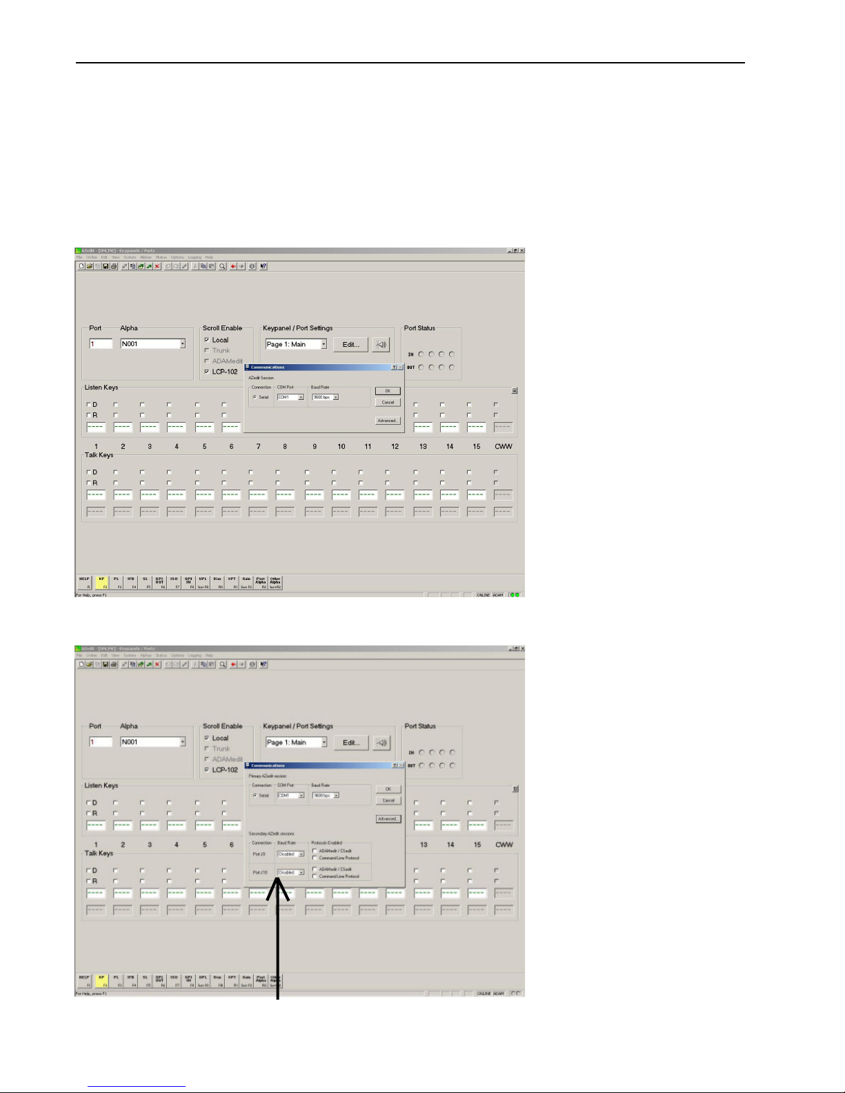
• Select “ADVANCED” – (must be connected to matrix to see this screen, see Figure 1.)
• Then Communication screen (see Figure 2.), Secondary AZedit Sessions J9/J10
• Advanced Settings (ADAM Only)
Remember, operationally J9 becomes J7 & J10 becomes J8 when PC dip switch S1-6 is “ON”. AZedit will
not change these port screen designations
15
Page 16
ADAM Dual Bus Expander
DBX Multiple AZedit Sessions
Baud Rate: Select the highest baud rate that will work correctly. Unlike the baud rate setting for the primary AZedit
session, which is set by a master controller DIP switch, the baud rates for second and third computers are set in software,
and there are no DIP switches for this.
This configuration information is stored in configuration flash, (U3/U5), so the intercom will remember it. However, if the
intercom loses its config flash for any reason (e.g. it gets a 1st birthday, perhaps because a new version of firmware is
downloaded to it), it will come up with J9 and J10 disabled by default.
Figure 1
Figure 2
J9 &J10 are in reality J7 & J8 on
ADAM controller breakout panel
16
Page 17

ADAM Dual Bus Expander
ADAM DBX Upgrade
Single frame ADAM to multi-frame ADAM DBX or existing multi-frame SBX to DBX
Caution: Read entire procedure before attempting upgrade
Important: Be aware there can be a 2 minute period for each group of cards selected during the
download process where the master controller will take each Audio I/O card off line and
reprogram its firmware. Any disruption during this period (loss of power, card removal,
manually resetting cards) will result in I/O card failure! If this happens, you will either have to
return the affected cards for replacement, or you will have to remove the EEPROM chips from
the affected cards and manually reprogram them with an EEPROM programmer. Since this
could potentially result in a major disruption in communications, we recommend that you only
update a limited number of I/O cards at a time, and updating should be performed during noncritical periods of intercom usage.
Make sure AZedit is the active window, and not the help file. (Click anywhere on the AZedit window
to make it the active window.) Then, press Ctrl+Shift+D on the computer keyboard. This will open the
Firmware Download dialog.
Note: If Ctrl+Shift+D does not work, firmware download may be disabled. To enable this feature, go
to the Options menu and select Preferences. Then, click on the Advanced tab. In the
Advanced settings, place a check next to Allow firmware download, then click Apply. Click OK
to exit. You should now be able to use the firmware download feature.
UPGRADE PROCEDURE
Minimum requirements:
a) Master Controller cards must have Altera ver 4.1 or higher and RAM installed in U10-U13 & U15-U18.
If Master Controllers have ver 8.x firmware, a M/C card swap is necessary to bring the Masters up to
the level capable of a DBX upgrade.
b) DBX cards must have firmware ver 1.2.1 or higher and Altera ver 1.1 or higher.
c) AIO cards ver 10.0.3 (or higher).
d) UIO256 requires firmware ver 2.0 (checksum 78b5, wired in a multi-drop mode, dip switch S1-2
closed and RS485 data going to J2 of each UIO256 (or higher).
e) PAP940, 951, 952 requires firmware ver 7.3.x (or higher).
f) Trunking, requires firmware ver 7.4.0 and CStrunk ver 7.3.1 (or higher). Trunking should be upgraded
first before the DBX’s.
g) LCP102’s require ver 1.4 (or higher).
h) AZedit ver 1.07.06 (or higher).
DBX Upgrade
1. Save current intercom setup file to disk (very important).
2. If trunking, disconnect from Trunk Master.
3. Download ver 10.0.2 or higher AIO firmware to all AIO cards half a frame at a time with older existing
SBX controller cards still in frames. Confirm successful download with AZedit in Status/Software
Versions/AIO Cards. (fig. 1)
• If physically changing MC and DBX flash, continue with steps 4-16. If downloading, skip these steps
and proceed to steps 17-28.
4. Power down entire system.
5. Change existing back cards in the appropriate frame slots to DBX back cards. See frame layout
drawings relating to DBX system size and install coax links per cable diagram.
6. Remove all slave frame Master Controller cards and back cards. These slots will remain blank and
never used again. DO NOT use for spare card storage.
7. In frame 1 only, change Master and Standby Controller flash U2 & U4 to new DBX Peripheral
Controller flash ver 10.2.x. These cards will be heretofore referred to as “Peripheral Controllers” (PC).
17
Page 18

ADAM Dual Bus Expander
8. Put only one DBX card in frame 1, slot 9 (turn on DIP 7), and one PC card in frame 1, slot 19 (also
needs dip 7 on).
9. Power up frame 1 ONLY and ensure AZedit goes on line. Resize to new final system size under
Options/Intercom Configuration. Default is 3 frame redundant audio system. (fig. 2)
10. Check “use DBX cards” in Options/Intercom Configuration/Resources, if not already detected, always
check “use test audio”. You can also “use redundant audio” only if it is appropriate for the system
being set up]. (fig. 2) Also check Options page to be sure number of talk levels, remote trunk master
(
not to be confused with local trunking
birthday again if you need to change them later. (fig 4)
11. If applicable, select “Apply” and the system will reconfigure itself and re-start.
12. After system has settled down, plug in the standby DBX into slot 8 of frame 1 and let it update. Next
plug in the standby PC into slot 20 of frame 1, (remember both dips 7 need to be on) and let it update.
13. Insert all remaining DBX cards in each slave frame (dips 7 must be off) and power up all frames. This
may take a little time - be patient. Verify I/O cards can be seen with proper versions in Status/
Software Versions/AIO Cards. (fig. 1)
14. Check DBX Link Status. (fig 3)
15. Send saved intercom setup file from step 1 above if necessary.
16. Re-connect Trunk Master if appropriate.
If Downloading PC’s and DBX Cards
(If steps 1-16 above have been performed, ignore this section)
), and other options are set now, otherwise the system will first
17. Pull MC #1 (slot 19), ensure AZedit is on line, and download MC #2 (slot 20). Pull MC #2 (slot 20)
and put back MC #1 (slot 19), ensure AZedit is on line, and download it.
18. After downloading both MC’s (now PC’s), leave only PC #1 in slot 19.
19. Power down system and install DBX back cards in the appropriate card slots in frame 1.
20. Install a DBX card in slot 9 of frame 1 and power up. Download this card and when completed,
remove it and install another in the same slot 9 and download it.
21. Resize to new final system size under Options/Intercom Configuration. Default is 3 frame redundant
audio system. (fig. 2)
22. Check “use DBX cards” in Options/Intercom Configuration/Resources, if not already detected, always
check “use test audio”. You can also “use redundant audio” only if it is appropriate for system being set
up].(fig. 2) Also check Options page to be sure number of talk levels, remote trunk master (
confused with local trunking
again if you need to change them later. (fig. 4)
23. If applicable, select “Apply” and the system will reconfigure itself and re-start.
24. When the resize is done, you can install the first downloaded DBX into slot 8 and plug in the second
PC into slot 20 as well.
25. Install DBX back cards and DBX controller cards in all slave frames, power up these frames and
download all slave DBX’s. Verify I/O cards can be seen with proper versions in Status/Software
Versions/AIO Cards. (fig. 1)
Note: Switch 7 should be in the OFF position for the slave frames on the DBX card.
26. Check DBX Link Status. (fig 3)
27. Re-send saved setup file from step 1 if required.
28. Re-connect Trunk Master if appropriate.
), and other options are set now, otherwise the system will first birthday
not to be
Special Note: In 2 & 3 frame non-redundant systems, the last 4 ports in each frame will be unusable
due to test audio. This will affect overall system layout breakout cabling.
18
Page 19

ADAM Dual Bus Expander
Figure 1. Verify software versions (steps 3,13, 25)
Figure 2. Set up frame size and DBX options (steps 9,19, 20)
19
Page 20

ADAM Dual Bus Expander
Figure 3. DBX Link Status (steps 14)
Figure 4. Set up Options page (steps 10, 20)
20
Page 21

ADAM Dual Bus Expander
d
8
f F
l
P
Number/Frme
Total/S
d
Number/Frme
Total/S
e
F
d
e
e
e
ADAM Intercom Size vs. SBX/DBX and AIO Card Population
DBX Card P opulat io n.XLS
Number of Slots 17
Number of Panels Per I/O Car
Number Ports Bus Expanders IO Cards Timeslots Notes
o
ramesTota
1136136000171717 No BXs
2256128129163215
3 360 120 2 6 8,9 15 45 13
4 448 112 3 12 8,9,10 14 56 11
Number of Slots 17
Number of Panels Per I/O Car d 8
Number Ports Bus Expanders IO Cards Timeslots Notes
of Frames Total Increas e
1136136000171717N/ANo BXs
2 256 120129163215128
3 384 128139164816128
4 480 96 2 8
5 600 120 2 10
6 672 72 3 18
7 784 112 3 21
8 832 48 4 32
9 936 104 4 36
10 960 24 5 50
11 1056 96 5 55
er Frame
Number/Frm
Total/Sys. Slots Used
Single Bus Expanders with 8 port Analog I/O Cards
ys.Slots Use
Dual Bus Expanders (no Redundant Audio) with 8 port Analog I/O Cards
Number /Frm
8,9
8,9
8,9,10
8,9,10
7,8,9,10
7,8,9,10
7,8,9,10,11
7,8,9,10,11
15 60 12 120
15 75 15 120
14 84 9 112
14 98 14 112
13 104 6 104
13 117 13 104
12 120 3 96
12 132 12 96
ys.Increas
Total/ Sys. Increas e Forwarded
7/2/ 2000
orwarde
2 and 3 frame s ystems above loose 4 ports per frame due to Test Audio enabled. 2 Fr ame = 248 ports, 3 Frame = 372 port s.
Note:
Number of Slots 17
Number of Panels Per I/O Car d 8
Number Ports Bus Expanders IO Cards Timeslots Notes
of Frames Total Increas e
1 136 136 0 0 17 17 17 N/A No BXs
224012024
336010426
4 448 88 3 12
5 520 72 4 20
6 576 56 5 30
7 616 40 6 42
Number/Frm
Total/Sys. Slots Used
Dual Bus Expanders (Redundant Audio) with 8 port Analog I/O Cards
and Single Bus Expanders with 8 port Analog I/O Cards
umber/FrmTotal/ Sys. Increas e Forwarded
8,9
8,9
8,9,10
7,8,9,10
7,8,9,10,11
6,7,8,9,10,11
15 30 13 120
15 45 15 120
14 56 11 112
13 65 9 104
12 72 7 96
11 77 5 88
21
Page 22

ADAM DBX LINK MAPPING
Frame Number/DBX Slot Number
ADAM Dual Bus Expander
1/9
A
B
DBX Card
Por t A
A
2/9
B
1/9
A
B
DIAGRAM KEY
1/9
A
B
2 Frame Redundant
240 ports
1/8
A
B
DBX Card
Por t B
B
2/8
A
2 Frame Non-Redundant
248 - 256 ports
A
A
2/9
B
3 Frame
Non-Redundant
372 of 384
1/9
B
A
1/9
ports
A
B
2/9
B
B
3/9
A
1/9
A
B
B
3/9
A
3 Frame Redundant
360 ports
B
2/8
A
1/8
A
B
A
2/9
B
A
4/8
B
A
3/8
B
A
3/9
B
4 Frame Non-Redundant
480 ports
Partial redundancy does exist
between frames1/2 & 3/4 due to
two coax paths between the
respective frames
A
2/8
B
1/8
A
B
A
2/9
B
A
3/8
B
A
4/9
B
22
Page 23

ADAM Dual Bus Expander
23
Page 24

ADAM Dual Bus Expander
24
Page 25

ADAM Dual Bus Expander
25
Page 26

ADAM Dual Bus Expander
26
Page 27

ADAM Dual Bus Expander
27
Page 28

ADAM Dual Bus Expander
28
Page 29

ADAM Dual Bus Expander
2 FRAME NON-REDUNDANT DBX SYSTEM 2 FRAME REDUNDANT DBX SYSTEM
FRAME & AIO KEYPA NEL & TIF REAR DIP SWITC H SETTINGS (DS-4 t hru DS-7) D=down FRAME & AIO KEYP ANE L & TIF REA R DIP SWITCH SE TTINGS ( DS-4 t hru DS-7) D=down
M ATR IX SYST EM
2-14 29 225 226 227 228 229 230 231 232 2-16 29 225 226 227 228 229 230 231 232
2-15 30 233 234 235 236 237 238 239 240 2-17 30 233 234 235 236 237 238 239 240
2-16 31 241 242 243 244 245 246 247 248
2-17 32 249 250 251 252 253 254 255 256 DB X card in fr ame slot s 8 & 9
DBX card in frame slot 9
Yellow shaded ports not available due to Test Audio enabled
Green shading indicates presence of bus expanders
2-1328217218219 220 221 222 223 224 2-1528217218219 220 221 222 223 224
2-12 27 209 210211 212 213 214 2152162-14 27 209 210211212 2 13 2 14 2 15 2 16
2-1025193 194 195 196 197 198 199 200 2-1225193 194 195 196 197 198 199 200
2-11 26 201 202 203 204 205 206 207 208 2-13 26 201 202 203 204 205 206 207 208
2-8 24 185 186 187 188 189 190 191 192 2-11 24 185 186 187 188 189 190 191 192
2-6 22 169 170 171 172 173 174 175 176 2- 7 22 169 170 171 172 173 174 175 176
2-7 23 177 178 179 180 181 182 183 184 2-1023177 178 179 180 181 182 183 184
2-5 21 161 162 163 164 165 166 167 168 2-6 21 161 162 163 164 165 166 167 168
2-4 20 153 154 155 156 157 158 159 160 2-5 20 153 154 155 156 157 158 159 160
2-3 19 145 146 147 148 149 150 151 152 2-4 19145 146 147 148 149 150 151 152
2-2 18 137 138 139 140 141 142 143 144 2-3 18137 138 139 140 141 142 143 144
1-1716121 122 123 124 125 126 127 128 2-1 16121 122 123 124 125 126 127 128
1-1615113114115116117118119120 1-1715113 114115116117118119120
2-1 17 129 130 131 132 133 134 135 136 2-2 17129 130 131 132 133 134 135 136
1-1514105 106 107 108 109 1101111121-1614105 106 107 108 109 110111 112
1-13 12 8990919293949596 1-1412 8990919293949596
1-14 13 979899100 101 102 103 104 1-1513 979899100 101 102 103 104
1-1211 8182838485868788 1-1311 8182838485868788
1-10 9 65 66 67 68 69 70 71 72 1-11 9 6566676869707172
1-11 10 7374757677787980 1-1210 7374757677787980
1-7 7 4950 515253545556 1-7 7 4950 515253545556
1-8 8 5758596061626364 1-10 8 57 58 59 60 61 62 63 64
1-4 4 252627282930 3132 1-4 4 252627282930 3132
1-5 5 3334353637383940 1-5 5 3334353637383940
1-6 6 4142434445464748 1-6 6 4142434445464748
SLOT # NUM BER I.D .-1 I.D.-2 I.D.-3 I.D.-4 I.D.-5 I.D.-6 I.D.-7 I.D .-8 SLOT # NUM BER I.D.- 1 I.D.-2 I.D.-3 I.D .-4 I.D.-5 I.D.-6 I.D.-7 I.D.-8
1-3 3 171819 2021222324 1-3 3 171819 2021222324
AIO CARD DUUU UDUU DDUU UUDU DUDU UDDU DDDU UUUD AIO CARD DUUU UD UU D D UU UUD U D UD U UD DU DD D U UUUD
1-2 2 9 10111213141516 1-2 2 9 10111213141516
1-1 1 12345678 1-1 1 12345678
MATRIX PORT / DIP SWITCH TABLE - ADAM 256
U=u p M AT RIX S YSTEM
MATRIX PORT / DIP SWITCH TABLE - ADAM 240
U=u p
29
Page 30

ADAM Dual Bus Expander
U=up
MATRIX PORT / DIP SWITCH TABLE - ADAM 360
DUUU UDUU DD UU UUDU DUD U UD D U DD DU UUUD
AIO CARD
MA TRIX SYSTEM
U=up
Green shadi ng indicat es presenc e of bus expanders
MATRIX PORT / DIP SWITCH TABLE - ADAM 384
DUUU UDUU DD UU UUDU DUD U UDD U DD DU UUUD
DB X card in f rame slo t 9 yello w shaded port s no t avai lable due to Tes t Audi o enabled .
1-1 1 12345678 1-1 1 12345678
1-2 2 9 101112131415161-2 2 9 10111213141516
1-3 3 1718192021222324 1-3 3 1718192021222324
1-4 4 252627282930 3132 1-4 4 252627282930 3132
1-5 5 3334353637383940 1-5 5 3334353637383940
1-6 6 4142434445464748 1-6 6 4142434445464748
1-7 7 4950515253545556 1-7 7 4950515253545556
1-8 8 575859 60 61626364 1-10 8 57 58 59 60 61 62 63 64
1-1110 7374757677787980 1-1210 7374757677787980
1-10 9 65 66 67 68 69 70 71 72 1-11 9 656667686970 7172
1-1211 8182838485868788 1-1311 8182838485868788
1-1312 8990 919293949596 1-1412 8990 919293949596
AIO CARD
SLOT # NUM B ER I.D- 1 I.D.- 2 I.D.-3 I.D.- 4 I.D.-5 I.D.- 6 I.D.- 7 I.D.- 8 SLOT # NUM B ER I.D- 1 I.D.- 2 I.D.-3 I.D.- 4 I.D.- 5 I.D.-6 I.D.- 7 I.D.- 8
MA TRIX SYSTEM
FRAME & AIO KEYPA NEL & TIF R EAR DIP SWITCH SETT INGS (DS-4 thr u DS-7) D=do wn FRAM E & AIO KEYP ANEL & T IF REAR DIP SWITCH SET TINGS (DS-4 t hru DS-7) D=do wn
3 FRAME NON-REDUNDANT DBX SYSTEM 3 FRAME REDUNDANT DBX SYSTEM
1-1413 979899100 101 102 103 104 1-1513979899100 101 102 103 104
2-1 17129 130 131 132 133 134 135 136 2-2 17129 130 131 132 133 134 135 136
1-1514105 106 107 108 109 1101111121-1614105 106 107 108 109 110111112
1-1615113114115116117118119120 1-1715113114115116117118119120
1-1716121 122 123 124 125 126 127 128 2- 1 16121 122 123 124 125 126 127 128
2-2 18137 138 139 140 141 142 143 144 2-3 18137 138 139 140 141 142 143 144
2-3 19145 146 147 148 149 150 151 152 2-4 19145 146 147 148 149 150 151 152
2-4 20 153 154 155 156 157 158 159 160 2-5 20 153 154 155 156 157 158 159 160
2-5 21 161 162 163 164 165 166 167 168 2-6 21 161 162 163 164 165 166 167 168
2-6 22 169 170 171 172 173 174 175 176 2-7 22 169 170 171 172 173 174 175 176
2-7 23 177 178 179 180 181 182 183 184 2- 1023177 178 179 180 181 182 183 184
2-8 24 185 186 187 188 189 190 191 192 2-1124185 186 187 188 189 190 191 192
2-11 26 201 202 203 204 205 206 207 208 2- 13 26 201 202 2 03 204 205 206 207 208
2-1025193 194 195 196 197 198 199 200 2-1225193 194 195 196 197 198 199 200
2-12 27 209 2102112122132142152162-14 27 209 210211212213214215216
2-1328217218219 220 221 222 223 224 2- 1528217218219 220 221 222 223 224
2-14 29 225 226 227 228 229 230 231 232 2-16 29 225 226 227 228 229 230 231 232
2-15 30 233 234 235 236 237 238 239 240 2-17 30 233 234 235 236 237 238 239 240
2-16 31 241 242 243 244 245 246 247 248 3-1 31 2 41 242 243 244 245 246 247 248
2-17 32 249 250 251 252 253 254 255 256 3-2 32 249 250 251 252 253 254 255 256
3-1 33 257 258 259 260 261 262 263 264 3- 3 33 257 258 259 260 261 262 263 264
3-2 34 265 266 267 268 269 270 271 272 3- 4 34 265 266 267 268 269 270 271 272
3-3 35 273 274 275 276 277 278 279 280 3- 5 35 273 274 275 276 277 278 279 280
3-4 36 281 282 283 284 285 286 287 288 3- 6 36 281 282 283 284 285 286 287 288
3-5 37 289 290 291 292 293 294 295 296 3- 7 37 289 290 291 292 293 294 295 296
3-6 38 297 298 299 300 301 302 303 304 3-10 38 297 298 2 99 300 301 302 303 304
3-7 39 305 306 307 308 309 3 103113123-11 39 305 306 307 30 8 309 310311312
3-8 40 313314315316317318319 320 3-1240313314315316317318319 320
3-11 42 329 330 331 332 333 334 335 336 3-14 42 329 330 331 332 333 334 335 336
3-10 41 321 322 323 324 325 326 327 328 3-13 41 3 21 322 323 324 325 326 327 328
3-12 43 337 338 339 340 341 342 343 344 3-15 43 337 338 339 340 341 342 343 344
3-13 44 345 346 347 348 349 350 351 352 3-16 44 345 346 347 348 349 350 351 352
3-14 45 353 354 355 356 357 358 359 360 3-17 45 353 354 355 356 357 358 359 360
3-15 46 361 362 363 364 365 366 367 368
3-16 47 369 370 371 372 373 374 375 376 DB X cards i n frame s lot s 8 & 9
3-17 48 377 378 379 380 381 382 383 384
30
Page 31

Green shading indic ates pres ence of bus expanders DB X cards i n frame slo ts 8 & 9
ADAM Dual Bus Expander
4 FRA M E NON-RED UNDAN T DBX SYSTEM
FRAME & AIO KEYPANEL & TIF REAR DIP SWITCH SETTINGS (DS-4 thru DS-7) D=down FRAM E & A IO KEYPA NEL & T IF REA R DIP SWITC H SETT INGS (DS- 4 thru D S-7) D=do wn
M ATR IX S YSTEM MATRIX PORT / DIP SWITCH TABLE - ADAM 480
2-16 29 225 226 227 228 229 230 231 232 4-16 59 465 466 467 468 469 470 471 472
2-17 30 233 234 235 236 237 238 239 240 4-17 60 473 474 475 476 477 478 479 480
2-1528217218 219 220 221 222 223 224 4-15 58 457 458 459 460 461 462 463 464
2-1427209210211212213214 215 216 4-14 57 449 450 451 452 453 454 455 456
2-10 2 3 17 7 17 8 17 9 18 0 18 1 18 2 18 3 18 4 4 - 10 5 3 4 17 4 18 4 19 420 421 422 423 424
2-12 25 193 194 195 196 197 198 199 200 4-12 55 433 434 435 436 437 438 439 440
2-13 26 201 202 203 204 205 206 207 208 4-13 56 441 442 443 444 445 446 447 448
2 - 6 2 1 16 1 16 2 16 3 16 4 165 166 167 168 4-6 51 401 402 403 404 405 406 407 408
2 - 7 2 2 16 9 17 0 17 1 17 2 173 174 175 176 4-7 52 409 410 411 412 413414415416
2 - 11 2 4 18 5 18 6 18 7 18 8 189 190 191 192 4-11 54 425 426 427 428 429 430 431 432
2 - 2 17 12 9 13 0 13 1 13 2 133 134 135 136 4-2 47 369 370 371 372 373 374 375 376
2 - 3 18 13 7 13 8 13 9 14 0 14 1 14 2 143 144 4-3 48 377 378 379 380 381 382 383 384
2-4 19 145 146 147 148 149 150 151 152 4-4 49 385 386 387 388 389 390 391 392
2-5 20 153 154 155 156 157 158 159 160 4-5 50 393 394 395 396 397 398 399 400
1-17 15 113 114 115116 117118 119 120 3-17 45 353 354 355 356 357 358 359 360
1- 14 12 89 90 91 92 93 94 95 96 3-14 42 329 330 331 332 333 334 335 336
1-15 13 979899100101102103 104 3-15 43 337 338 339 340 341 342 343 344
1- 16 14 105 106 107 108 109 110 111 112 3-16 44 345 346 347 348 349 350 351 352
2-1 16 121 122 123 124 125 126 127 128 4-1 46 361 362 363 364 365 366 367 368
1- 13 11 81 82 83 84 85 86 87 88 3-13 41 321 322 323 324 325 326 327 328
1-12 10 7374757677787980 3-12 40 313314315316317318319320
1- 11 9 65 66 67 68 69 70 71 72 3-11 39 305 306 307 308 309 310 311 312
1- 10 8 57 58 59 60 61 62 63 64 3-10 38 297 298 299 300 301 302 303 304
1-4 4 25 26 27 28 29 30 31 32 3-4 34 265 266 267 268 269 270 271 272
1-5 5 33 34 35 36 37 38 39 40 3-5 35 273 274 275 276 277 278 279 280
1-6 6 41 42 43 44 45 46 47 48 3-6 36 281 282 283 284 285 286 287 288
1-7 7 49 50 51 52 53 54 55 56 3-7 37 289 290 291 292 293 294 295 296
SLOT # N UM B ER I.D -1 I.D .-2 I.D.- 3 I.D.- 4 I.D .-5 I.D.-6 I.D .-7 I.D.- 8 S LOT # NUM B ER I.D -1 I.D.-2 I.D .-3 I.D.-4 I.D .-5 I.D.-6 I.D .-7 I.D.- 8
AIO CARD
1- 2 2 9 10111213141516 3-2 32 249 250 251 252 253 254 255 256
1- 3 3 17 18 19 20 21 22 23 24 3-3 33 257 258 259 260 261 262 263 264
1- 1 1 1 2 3 4 5 6 7 8 3-1 31 241 242 243 244 245 246 247 248
DUUU UDUU DDUU UUDU DUDU UDDU DDDU UUUD
U=up
M AT RIX SYSTEM M ATRIX PORT / DIP SWITCH TABLE - ADAM 480
AIO CARD
DUUU UDUU DDUU UUDU DUDU UDDU DDDU UUUD
U=u p
31
Page 32

ADAM Dual Bus Expander
U=up
MATRIX PORT / DIP SWITCH TABLE - ADAM 448
DUUU UDUU DDUU UUDU DUDU UDDU DDDU UUUD
DBX cards in frame slots 8, 9 & 10
AIO CARD
M AT RIX SY STEM
U=u p
Green shading i ndicates presence o f bus expanders
MATRIX PORT / DIP SWITCH TABLE - ADAM 448
D UUU UD UU D D UU UUDU D UD U UD DU D DD U UUUD
1-1 1 1 2 3 4 5 6 7 8 3-1 29 225 226 227 228 229 230 231 232
1-2 2 9 101112131415 16 3-2 30 233 234 235 236 237 238 239 240
1-3 3 171819 20 21 22 23 24 3-3 31 241 242 243 244 245 246 247 248
AIO CARD
SLOT # N UM B ER I.D-1 I.D.- 2 I.D .-3 I.D.- 4 I.D.-5 I.D.-6 I.D.-7 I.D.-8 SLOT # N UM B ER I.D- 1 I.D .-2 I.D.- 3 I.D.-4 I.D.-5 I.D.-6 I.D.-7 I.D.-8
M AT RIX SYST EM
FRAME & AIO KEYP AN EL & TIF R EAR D IP SWITCH SETTIN GS (DS-4 t hru D S-7) D=do wn FRAME & AIO KEYPA NEL & TIF REAR DIP SWITCH SETTINGS (DS-4 thru DS-7) D=down
4 FRAME REDUNDANT DBX SYSTEM
1-4 4 25 26 27 28 29 30 31 32 3-4 32 249 250 251 252 253 254 255 256
32
1-5 5 33 34 35 36 37 38 39 40 3-5 33 257 258 259 260 261 262 263 264
1-6 6 41 42 43 44 45 46 47 48 3-6 34 265 266 267 268 269 270 271 272
1-7 7 49 50 51 52 53 54 55 56 3-7 35 273 274 275 276 277 278 279 280
1-11 8 57 58 59 60 61 62 63 64 3-11 36 281 282 283 284 285 286 287 288
1- 12 9 65 66 67 68 69 70 71 72 3-12 37 289 290 291 292 293 294 295 296
1- 13 10 7374757677787980 3-13 38 297 298 299 300 301 302 303 304
1- 15 12 8990919293949596 3-1540313314315316317318 319 320
1- 1613979899100 101 102 103 104 3-16 41 321 322 323 324 325 326 327 328
1- 1714105106 107 108 109 1101111123-17 42 329 330 331 332 333 334 335 336
2-1 15 113114115116117118119120 4-1 43 337 338 339 340 341 342 343 344
2-2 16 121 122 123 124 125 126 127 128 4-2 44 345 346 347 348 349 350 351 352
2-3 17 129 130 131 132 133 134 135 136 4-3 45 353 354 355 356 357 358 359 360
2-4 18 137 138 139 140 141 142 143 144 4-4 46 361 362 363 364 365 366 367 368
2-5 19 145 146 147 148 149 150 151 152 4-5 47 369 370 371 372 373 374 375 376
2-6 20 153 154 155 156 157 158 159 160 4-6 48 377 378 379 380 381 382 383 384
2-7 21 161 162 163 164 165 166 167 168 4-7 49 385 386 387 388 389 390 391 392
2-1122169170 171 172 173 174 175 176 4-11 50 393 394 395 396 397 398 399 400
2-12 23 177 178 179 180 181 182 183 184 4-12 51 401 402 403 404 405 406 407 408
2-13 24 185 186 187 188 189 190 191 192 4-13 52 409 410411412413414415416
2-14 25 193 194 195 196 197 198 199 200 4-1453417418419 420 421 422 423 424
2-15 26 201 202 203 204 205 206 207 208 4-15 54 425 426 427 428 429 430 431 432
2-16 27 209 2102112122132142152164-16 55 433 434 435 436 437 438 439 440
2-17 28 217 218 219 220 221 222 223 224 4-17 56 441 442 443 444 445 446 447 448
1- 1411 8182838485868788 3-14 39 305 306 307 308 309 310311312
Page 33

3-17 45 353 354 355 356 357 358 359 360
3-16 44 345 346 347 348 349 350 351 352
3-15 43 337 338 339 340 341 342 343 344
3-14 42 329 330 331 332 333 334 335 336
3-13 41 321 322 323 324 325 326 327 328
3-1240313314315316317318319 320
ADAM Dual Bus Expander
5 FRAME NON-REDUNDANT DBX SYSTEM
FRAM E & AIO KEYP AN EL & TIF REA R DIP SWITC H SETTIN GS (DS-4 t hru DS-7) D=do wn FRA ME & A IO KEYP AN EL & TIF REA R DIP SWITC H SETTIN GS (DS-4 t hru DS-7) D=do wn
M ATR IX SYSTEM
3-10 38 297 298 299 300 301 302 303 304
3-11 39 305 306 307 308 309 310311312
3-7 37 289 290 291 292 293 294 295 296
3-6 36 281 282 283 284 285 286 287 288
3-5 35 273 274 275 276 277 278 279 280
3-4 34 265 266 267 268 269 270 271 272
3-3 33 257 258 259 260 261 262 263 264
3-2 32 249 250 251 252 253 254 255 256 DB X cards in f rame sl ots 8 & 9
3-1 31 241 242 243 244 245 246 247 248
2-17 30 233 234 235 236 237 238 239 240 5-17 75 593 594 595 596 597 598 599 600
2-16 29 225 226 227 228 229 230 231 232 5-16 74 585 586 587 588 589 590 591 592
2-1528217218219 220 221 222 223 224 5-15 73 577 578 579 580 581 582 583 584
2-14 27 209 2102112122132142152165-14 72 569 570 571 572 573 574 575 576
2-13 26 201 202 203 204 205 206 207 208 5-13 71 561 562 563 564 565 566 567 568
2-1225193 194 195 196 197 198 199 200 5-12 70 553 554 555 556 557 558 559 560
2-1124185 186 187 188 189 190 191 192 5-11 69 545 546 547 548 549 550 551 552
2-1023177 178 179 180 181 182 183 184 5-10 68 537 538 539 540 541 542 543 544
2-7 22 169 170 171 172 173 174 175 176 5-7 67 529 530 531 532 533 534 535 536
2-6 21 161 162 163 164 165 166 167 168 5-6 66 521 522 523 524 525 526 527 528
2-5 20 153 154 155 156 157 158 159 160 5-5 65 513514515516517518519 520
2-4 19145 146 147 148 149 150 151 152 5-4 64 505 506 507 508 509 510511512
2-1 16121 122 123 124 125 126 127 128 5-1 61 481 482 483 484 485 486 487 488
1-11 9 656667686970 7172 4-11 54 425 426 427 428 429 430 431 432
1-4 4 25 26 27 28 29 30 31 32 4-4 49 385 386 387 388 389 390 391 392
1-5 5 33 34 35 36 37 38 39 40 4-5 50 393 394 395 396 397 398 399 400
1-6 6 41 42 43 44 45 46 47 48 4-6 51 401 402 403 404 405 406 407 408
1-7 7 4950 515253545556 4-7 52 409410411412413414415416
1-10 8 57 58 59 60 61 62 63 64 4-1053417418419 420 421 422 423 424
1-1210 7374757677787980 4-12 55 433 434 435 436 437 438 439 440
1-1311 8182838485868788 4-13 56 441 442 443 444 445 446 447 448
1-1412 8990919293949596 4-14 57 449 450 451 452 453 454 455 456
1-1513979899100 101 102 103 104 4- 15 58 457 458 459 460 461 462 463 464
1-1614105 106 107 108 109 1101111124-16 59 465 466 467 468 469 470 471 472
1-1715113114115116117118119120 4-17 60 473 474 475 476 477 478 479 480
2-2 17129 130 131 132 133 134 135 136 5-2 62 489 490 491 492 493 494 495 496
2-3 18137 138 139 140 141 142 143 144 5- 3 63 497 498 499 500 501 502 503 504
1-3 3 171819 20 21 22 23 24 4-3 48 377 378 379 380 381 382 383 384
1-2 2 9 10111213141516 4-2 47 369 370 371 372 373 374 375 376
1-1 1 12345678 4-146361362363364365366367368
SLOT # N UM B ER I.D-1 I.D.- 2 I.D .-3 I.D .-4 I.D .-5 I.D .-6 I.D .-7 I.D .-8 SLOT # NUM BER I.D-1 I.D .-2 I.D .-3 I.D .-4 I.D .-5 I.D.-6 I.D .-7 I.D .-8
AIO CARD
DUUU UDUU DDUU UUDU DUDU UDDU DDDU UUUD
MATRIX PORT / DIP SWITCH TABLE - ADAM 600
U=up
Green shading indicates presence of bus expanders
AIO CARD
DUUU UDUU DDUU UUDU DUDU UDDU DDDU UUUD
M ATR IX SYSTEM
MATRIX PORT / DIP SWITCH TABLE - ADAM 600
U=up
33
Page 34

ADAM Dual Bus Expander
h
di
i
di
t
f b
d
U=up
ers
ex pan
us
o
presenc e
MATRIX PORT / DIP SWITCH TABLE - ADAM 520
DUUU UD UU DD UU UUD U D UD U UDD U D D DU UUUD
es
ca
n
ng
a
s
reen
M ATR IX SYST EM
MATR IX PORT / DIP SWITCH TABLE - ADAM 520
AIO CARD
U=u p
DUU U UD UU D D UU UUDU D UD U UD D U D DD U UUUD
1-1 1 12345678 4-140313314315316317318319320
1-2 2 9 10111213141516 4-2 41 321 322 323 324 325 326 327 328
1-3 3 171819 20 21 22 23 24 4-3 42 329 330 331 332 333 334 335 336
AIO CARD
SLOT # NUM BER I.D -1 I.D .-2 I.D .-3 I.D.-4 I.D.-5 I.D .-6 I.D.- 7 I.D.- 8 SLOT # N UM B ER I.D-1 I.D .-2 I.D.- 3 I.D.- 4 I.D .-5 I.D .-6 I.D.- 7 I.D.- 8
M ATR IX SYST EM
FRAM E & A IO KEYP ANEL & T IF REA R DIP SWITC H SETT INGS (DS-4 t hru DS- 7) D=d own FRAM E & AIO KEYPA NEL & TIF REAR DIP SWITCH SETTINGS (DS-4 thru DS-7) D=down
5 FRAME REDUNDANT DBX SYSTEM
1-4 4 25 26 27 28 29 30 31 32 4 -4 43 337 338 339 340 341 342 343 3 44
34
1-5 5 33 34 35 36 37 38 39 40 4-5 44 345 346 347 348 349 350 351 352
1-6 6 41 42 43 44 45 46 47 48 4-6 45 353 354 355 356 357 358 359 3 60
1-11 7 4950515253545556 4-11 46 361 362 363 364 365 366 367 368
1-12 8 57 58 59 60 61 62 63 64 4-12 47 369 370 371 372 373 374 375 376
1-13 9 65 66 67 68 69 70 71 72 4-13 48 377 378 3 79 380 381 382 383 384
1-1410 7374757677787980 4-14 49 385 38 6 387 388 389 390 391 392
2-1 14105 106 107 108 109 110111 112 5-1 53 417418419 420 421 422 423 424
1-1511 8182838485868788 4-15 50 393 394 395 396 397 398 399 400
1-1612 8990919293949596 4-16 51 401 402 403 404 405 406 407 408
1-1713 979899100 101 102 103 104 4-17 52 409 410411412413414415416
2-2 15113114115116117118119 120 5-2 54 425 42 6 427 428 429 430 431 432
2-3 16121 122 123 124 125 126 127 128 5-3 55 433 434 4 35 436 437 438 439 440
2-1120153 154 155 156 157 158 159 160 5-11 59 465 466 467 468 469 470 471 472
2-4 17129 130 131 132 133 134 135 136 5-4 56 441 442 443 444 445 446 447 4 48
2-5 18137 138 139 140 141 142 143 144 5-5 57 449 450 451 452 453 454 455 456
2-6 19145 146 147 148 149 150 151 152 5-6 58 457 458 459 460 461 462 463 4 64
2-1423177 178 179 180 181 182 183 184 5- 14 62 489 490 491 492 493 494 495 496
2-1322169 170 171 172 173 174 175 176 5- 13 61 481 482 483 484 485 486 487 4 88
2-1221161 162 163 164 165 166 167 168 5-12 60 473 474 4 75 476 477 478 479 480
3-1 27 209 210211212213214215216
3-3 29 225 226 227 228 229 230 231 232
3-2 28 217218219 220 221 222 223 224 DBX c ards in f rame slo ts 7, 8, 9, & 10
3-4 30 233 234 235 236 237 238 239 240
3-5 31 241 242 243 244 245 246 247 248
3-6 32 249 250 251 252 253 254 255 256
2-17 26 201 202 203 204 205 206 20 7 208 5- 1765513514515516517518519520
2-1625193 194 195 196 197 198 199 200 5-16 64 505 506 507 508 509 510511512
2-1524185 186 187 188 189 190 191 192 5- 15 63 497 498 499 500 501 502 503 5 04
3-11 33 257 258 259 260 261 262 263 264
3-12 34 265 2 66 267 268 269 270 271 272
3-13 35 273 2 74 275 276 277 278 279 280
3-14 36 281 282 283 284 285 286 28 7 288
3-15 37 289 2 90 291 292 293 294 29 5 296
3-16 38 297 2 98 299 300 301 302 303 304
3-17 39 305 3 06 307 308 309 310311312
Page 35

ADAM Dual Bus Expander
6 FRAME NON-REDUNDANT DBX SYSTEM
FRAME & AIO KEYP ANEL & T IF REAR D IP SWIT CH SETTINGS (DS- 4 thru DS-7) D =down FRAME & AIO KEYP ANEL & TIF R EAR D IP SWITC H SETT INGS (DS- 4 thr u DS-7) D=do wn
MA TRIX SYSTEM
SLOT # N UM BE R I.D-1 I.D.-2 I.D.-3 I.D.- 4 I.D .-5 I.D .-6 I.D.- 7 I.D .-8 SLOT # N UM BE R I.D-1 I.D.-2 I.D.-3 I.D.-4 I.D.- 5 I.D .-6 I.D .-7 I.D.- 8
3-17 42 329 330 331 332 333 334 335 336 6 -17 84 665 66 6 6 67 668 669 670 671 672
3-14 39 305 306 307 308 309 310311312 6-14 81 641 642 643 644 645 646 647 648
3-1540313314315316317318319 320 6-15 82 649 650 651 652 653 654 6 55 656
3-16 41 321 322 323 324 325 326 327 328 6-16 8 3 657 658 659 660 661 662 663 664
3-13 38 297 298 299 300 3 01 302 303 304 6- 13 80 633 634 635 636 637 638 639 640
3-12 37 289 290 291 292 293 294 295 296 6 -12 79 625 62 6 6 27 628 629 630 631 632
3-7 35 273 274 275 276 277 278 279 280 6-7 7 7 609 610 6 11612613614615616
3-11 36 281 282 283 284 285 2 86 287 288 6-1178617618619 620 621 622 623 624
Green sh ading indic ates presenc e of bus expanders DB X cards i n fram e slo ts 8, 9, & 10
3-6 34 265 266 267 268 269 270 271 272 6-6 7 6 601 602 603 604 605 606 607 608
3-5 33 257 258 259 260 2 61 262 263 264 6-5 75 593 594 595 596 597 598 599 600
3-4 32 249 250 251 252 253 254 255 256 6- 4 74 585 586 587 588 589 590 591 592
3-3 31 241 242 243 244 245 246 247 248 6-3 73 577 578 579 580 581 582 583 584
3-2 30 233 234 235 236 237 238 239 240 6-2 7 2 569 570 571 572 573 574 575 576
3-1 29 225 226 227 228 229 230 231 232 6- 1 71 561 562 563 564 565 566 5 67 568
2-1728217218219 220 221 222 223 224 5-17 70 553 554 555 556 557 558 559 560
2-16 27 209 210211212213214215216 5-16 69 545 546 547 548 549 55 0 551 552
2-15 26 201 202 203 204 205 206 207 208 5-15 6 8 537 538 539 540 541 542 543 544
2-1425193 194 195 196 197 198 199 200 5-14 6 7 529 530 531 532 533 534 535 536
2-1324185 186 187 188 189 190 191 192 5-13 66 521 52 2 5 23 524 525 526 527 528
2-1223177 178 179 180 181 182 183 184 5-1265513514515516517518519 520
2-1122169 170 171 172 173 174 175 176 5-11 64 505 506 507 508 509 510511512
2-1 16121 122 123 124 125 126 127 12 8 5-2 58 457 458 459 460 461 462 463 464
2-1 15113114115116117 118119120 5-1 57 449 450 451 452 453 454 455 456
1-11 8 57 58 59 60 61 62 63 64 4-11 5 0 393 394 395 396 397 398 399 400
1-7 7 4 9 50 51 52 53 54 55 56 4-7 49 385 386 3 87 388 389 390 391 392
1-6 6 41 42 43 44 45 46 47 4 8 4-6 48 377 378 379 380 381 382 383 384
1-5 5 3 3 34 35 36 37 38 39 40 4-5 47 369 370 371 372 373 374 375 376
1-4 4 2 5 26 27 28 29 30 31 32 4- 4 46 361 362 3 63 364 365 366 367 368
1-3 3 171819 20 21 22 23 24 4-3 45 353 354 355 356 357 358 359 360
1-12 9 65 66 67 68 69 70 71 72 4-12 51 401 40 2 403 404 405 406 4 07 408
1-1310 7374757677787980 4-13 52 409 410 411412413414415416
1-1411 8182838485868788 4-1453417418419 4 20 42 1 422 423 424
1-1512 8990919293949596 4-15 54 425 426 4 27 428 429 430 431 432
1-1613979899100 101 102 103 104 4-16 5 5 433 434 435 436 437 438 439 440
1-1714105 106 107 108 109 110111112 4 - 17 56 441 44 2 443 444 445 446 4 47 448
2-3 17129 130 131 132 133 134 135 136 5-3 59 465 466 467 468 469 470 471 472
2-4 18137 138 139 140 141 142 143 14 4 5-4 60 473 474 475 476 477 478 479 480
2-5 19145 146 147 148 149 150 151 15 2 5-5 61 481 482 4 83 484 485 486 487 488
2-6 20 153 154 155 156 157 158 159 160 5-6 62 489 490 491 492 493 494 495 496
2-7 21 161 162 163 164 165 166 167 168 5-7 63 497 498 499 500 501 502 503 504
1-2 2 9 10 111213141516 4-2 44 345 346 347 348 349 350 351 352
1-1 1 12345678 4-143337338339340341342343344
AIO CARD
DUU U UD UU D D UU UUD U DU DU UD D U D D D U UUUD
M AT RIX P ORT / DIP SWITC H T AB LE - ADAM 672
U=u p
M AT RIX SYSTEM
AIO CARD
DUUU UDUU DDUU UUDU DUDU UDDU DDDU UUUD
MATRIX PORT / DIP SWITCH TABLE - ADAM 672
U=u p
35
Page 36

ADAM Dual Bus Expander
U=up
MATRIX PORT / DIP SWITCH TABLE - ADAM 784
DUUU UDUU DDUU UUDU DUDU UDDU DDD U UUUD
7 FRA M E NON -RED UNDAN T D BX SYST EM
AIO CARD
M AT RIX SYSTEM
U=up
MATRIX PORT / DIP SWITCH TABLE - ADAM 784
DUUU UDUU DDUU UUDU DUDU UDDU DDDU UUUD
1-1 1 1 2 3 4 5 6 7 8 4-12 51 401 402 403 404 405 406 407 408
1- 2 2 9 10 11 12 13 14 15 16 4-13 52 409 410 411 412 413 414 415 416
1- 3 3 17 18 192021222324 4-14 53 417418419 420 421 422 423 424
1-4 4 25 26 27 28 29 30 31 32 4-15 54 425 426 427 428 429 430 431 432
1-5 5 33 34 35 36 37 38 39 40 4-16 55 433 434 435 436 437 438 439 440
1-6 6 41 42 43 44 45 46 47 48 4-17 56 441 442 443 444 445 446 447 448
1-7 7 49 50 51 52 53 54 55 56 5-1 57 449 450 451 452 453 454 455 456
1-11 8 57 58 59 60 61 62 63 64 5- 2 58 457 458 459 460 461 462 463 464
1-12 9 65 66 67 68 69 70 71 72 5-3 59 465 466 467 468 469 470 471 472
1-13 10 73 74 75 76 77 78 79 80 5- 4 60 473 474 475 476 477 478 479 480
1-14 11 81 82 83 84 85 86 87 88 5-5 61 481 482 483 484 485 486 487 488
AIO CARD
SLOT # NUM B ER I.D-1 I.D.- 2 I.D.-3 I.D.-4 I.D.- 5 I.D.-6 I.D.-7 I.D.- 8 S LOT # NUM BER I.D- 1 I.D .-2 I.D .-3 I.D.- 4 I.D.-5 I.D.- 6 I.D.-7 I .D.-8
M ATRIX SYSTEM
FRAM E & AIO KEYP ANEL & T IF REAR DIP SWITCH SETT INGS (DS-4 thru D S-7) D=down FRAM E & A IO KEYP ANEL & T IF REAR D IP SWITCH SETTINGS (D S-4 thru D S-7) D=down
1-15 12 89 90 91 92 93 94 95 96 5- 6 62 489 490 491 492 493 494 495 496
1-16 13 979899100101102103104 5-7 63 497 498 499 500 501 502 503 504
2-1 16 121 122 123 124 125 126 127 128 5-13 66 521 522 523 524 525 526 527 528
2-1 15 113 114 115 116 117 118 119 120 5-12 65 513 514 515 516 517 518 519 520
2-4 18 137 138 139 140 141 142 143 144 5- 15 68 537 538 539 540 541 542 543 544
2-3 17 129 130 131 132 133 134 135 136 5- 14 67 529 530 531 532 533 534 535 536
1-17 14 105 106 107 108 10 9 110 111 112 5 - 11 64 505 506 507 508 509 510 511 512
2-5 19 145 146 147 148 149 150 151 152 5-16 69 545 546 547 548 549 550 551 552
2-6 20 153 154 155 156 157 158 159 160 5-17 70 553 554 555 556 557 558 559 560
2-7 21 161 162 163 164 165 166 167 168 6-1 71 561 562 563 564 565 566 567 568
2-11 22 169 170 171 172 173 174 175 176 6-2 72 569 570 571 572 573 574 575 576
2-12 23 177 178 179 180 181 182 183 184 6-3 73 577 578 579 580 581 582 583 584
2-13 24 185 186 187 188 189 190 191 192 6-4 74 585 586 587 588 589 590 591 592
2-14 25 193 194 195 196 197 198 199 200 6-5 75 593 594 595 596 597 598 599 600
2-15 26 201 202 203 204 205 206 207 208 6-6 76 601 602 603 604 605 606 607 608
3-1 29 225 226 227 228 229 230 231 232 6-12 79 625 626 627 628 629 630 631 632
3-2 30 233 234 235 236 237 238 239 240 6-13 80 633 634 635 636 637 638 639 640
3-3 31 241 242 243 244 245 246 247 248 6-14 81 641 642 643 644 645 646 647 648
3-4 32 249 250 251 252 253 254 255 256 6-15 82 649 650 651 652 653 654 655 656
3-5 33 257 258 259 260 261 262 263 264 6-16 83 657 658 659 660 661 662 663 664
3-6 34 265 266 267 268 269 270 271 272 6-17 84 665 666 667 668 669 670 671 672
3-7 35 273 274 275 276 277 278 279 280 7-1 85 673 674 675 676 677 678 679 680
2-16 27 209 210 211 212 213214215216 6- 7 77 609 610 611 612 613 614 615 616
2-17 28 217 218 219 220 221 222 223 224 6- 1178617618619 620 621 622 623 624
3-11 36 281 282 283 284 285 286 287 288 7-2 86 681 682 683 684 685 686 687 688
3-12 37 289 290 291 292 293 294 295 296 7-3 87 689 690 691 692 693 694 695 696
3-13 38 297 298 299 300 301 302 303 304 7-4 88 697 698 699 700 701 702 703 704
3-14 39 305 306 307 308 309 310 311312 7-5 89 705 706 707 708 709 710 711 712
3-15 40 313 314 315 316 317 318 319 320 7-6 90 713 714 715 716 717 718 719 720
3-16 41 321 322 323 324 325 326 327 328 7-7 91 721 722 723 724 725 726 727 728
3-17 42 329 330 331 332 333 334 335 336 7-11 92 729 730 731 732 733 734 735 736
4-1 43 337 338 339 340 341 342 343 344 7-12 93 737 738 739 740 741 742 743 744
4-2 44 345 346 347 348 349 350 351 352 7-13 94 745 746 747 748 749 750 751 752
4-3 45 353 354 355 356 357 358 359 360 7-14 95 753 754 755 756 757 758 759 760
4-4 46 361 362 363 364 365 366 367 368 7-15 96 761 762 763 764 765 766 767 768
4-5 47 369 370 371 372 373 374 375 376 7-16 97 769 770 771 772 773 774 775 776
4-6 48 377 378 379 380 381 382 383 384 7-17 98 777 778 779 780 781 782 783 784
4-7 49 385 386 387 388 389 390 391 392 Green shading indi cates pres ence of bus expanders
4-11 50 393 394 395 396 397 398 399 400 DB X cards in frame s lot s 8, 9, & 10
36
Page 37

37
Page 38

38
Page 39

39
Page 40

40
Page 41

41
Page 42

42
Page 43

43
Page 44

44
Page 45

45
Page 46

46
Page 47

47
Page 48

48
Page 49

49
Page 50

50
Page 51

51
Page 52

52
Page 53

53
Page 54

54
Page 55

55
Page 56

56
Page 57

 Loading...