

Page 1

HANDBOOK OF INTERCOM
S
YSTEMS ENGINEERING
FIRST EDITION
38109-977 Preliminary Rev. 4, 3/2002
Page 2

The Fine Print
The Handbook of Intercom Systems Engineering, first edition, Copyright© 2000 by Telex Communications, Inc. All rights reserved. Printed in the United States of America. Except as permitted under the United States
Copyright Act of 1976, no part of this publication may be reproduced or distributed in any form or by any means,
electronic or mechanical, including photocopying and recording, or by any information storage or retrieval system
without the prior written permission of Telex Communications, Inc., unless such copying is expressly permitted by
federal copyright law.
Address copying inquires to:
Telex Communications, Inc.
Attn: VP, Intercom Products
12000 Portland Ave S
Burnsville, Minnesota 55337 USA
Information contained in this work has been created or obtained by Telex Communications Inc. from sources
believed to be reliable. However, Telex Communications, Inc. does not guarantee the accuracy or completeness of
the information published herein nor shall Telex Communications Inc. be liable for any errors, omissions, or damages arising from the use of this information. Telex Communications, Inc. is not attempting to provide professional
services through the publication of this book, but rather intends only to provide information. If such professional
services are necessary or desired, users of this book should seek such professional assistance.
Page 3

TABLE OF CONTENTS
Preface- - - - - - - - - - - - - - - - - - - - - - - - - - - - - - - - - - - - - - - - - - - - - - - - - - - - - - - - - - - - - - - - - - - - - - - - - -3
About the Authors - - - - - - - - - - - - - - - - - - - - - - - - - - - - - - - - - - - - - - - - - - - - - - - - - - - - - - - - - - - - - - - - -5
Intercoms—An Overview- - - - - - - - - - - - - - - - - - - - - - - - - - - - - - - - - - - - - - - - - - - - - - - - - - - - - - - - - - - -1
Introduction . . . . . . . . . . . . . . . . . . . . . . . . . . . . . . . . . . . . . . . . . . . . . . . . . . . . . . . . . . .1
Party-Line Systems . . . . . . . . . . . . . . . . . . . . . . . . . . . . . . . . . . . . . . . . . . . . . . . . . . . . .1
Matrix Systems . . . . . . . . . . . . . . . . . . . . . . . . . . . . . . . . . . . . . . . . . . . . . . . . . . . . . . .2
Wireless Systems . . . . . . . . . . . . . . . . . . . . . . . . . . . . . . . . . . . . . . . . . . . . . . . . . . . . . .2
Accessories . . . . . . . . . . . . . . . . . . . . . . . . . . . . . . . . . . . . . . . . . . . . . . . . . . . . . . . . .3
Before We Begin . . . . . . . . . . . . . . . . . . . . . . . . . . . . . . . . . . . . . . . . . . . . . . . . . . . . . . . .5
IFB . . . . . . . . . . . . . . . . . . . . . . . . . . . . . . . . . . . . . . . . . . . . . . . . . . . . . . . . . . . .5
ISO . . . . . . . . . . . . . . . . . . . . . . . . . . . . . . . . . . . . . . . . . . . . . . . . . . . . . . . . . . . .6
Tally. . . . . . . . . . . . . . . . . . . . . . . . . . . . . . . . . . . . . . . . . . . . . . . . . . . . . . . . . . . .6
The Rest Of The Book . . . . . . . . . . . . . . . . . . . . . . . . . . . . . . . . . . . . . . . . . . . . . . . . . . . . .6
Introduction to Party-Line
Intercom Systems - - - - - - - - - - - - - - - - - - - - - - - - - - - - - - - - - - - - - - - - - - - - - - - - - - - - - - - - - - - - - - - -7
Introduction . . . . . . . . . . . . . . . . . . . . . . . . . . . . . . . . . . . . . . . . . . . . . . . . . . . . . . . . . . .7
Some Definitions . . . . . . . . . . . . . . . . . . . . . . . . . . . . . . . . . . . . . . . . . . . . . . . . . . . . . . . .7
Party-Line (PL) systems / Conference Line Intercom Systems . . . . . . . . . . . . . . . . . . . . . . . . . . . . .7
Two-Wire . . . . . . . . . . . . . . . . . . . . . . . . . . . . . . . . . . . . . . . . . . . . . . . . . . . . . . . . .7
Balanced Line . . . . . . . . . . . . . . . . . . . . . . . . . . . . . . . . . . . . . . . . . . . . . . . . . . . . . .8
Full Duplex . . . . . . . . . . . . . . . . . . . . . . . . . . . . . . . . . . . . . . . . . . . . . . . . . . . . . . . .8
Decibel (dB) . . . . . . . . . . . . . . . . . . . . . . . . . . . . . . . . . . . . . . . . . . . . . . . . . . . . . . .8
Beltpack . . . . . . . . . . . . . . . . . . . . . . . . . . . . . . . . . . . . . . . . . . . . . . . . . . . . . . . . .8
Biscuit . . . . . . . . . . . . . . . . . . . . . . . . . . . . . . . . . . . . . . . . . . . . . . . . . . . . . . . . . .8
Main Station . . . . . . . . . . . . . . . . . . . . . . . . . . . . . . . . . . . . . . . . . . . . . . . . . . . . . . .8
Master Station . . . . . . . . . . . . . . . . . . . . . . . . . . . . . . . . . . . . . . . . . . . . . . . . . . . . . .8
Sidetone . . . . . . . . . . . . . . . . . . . . . . . . . . . . . . . . . . . . . . . . . . . . . . . . . . . . . . . . .8
Crosstalk . . . . . . . . . . . . . . . . . . . . . . . . . . . . . . . . . . . . . . . . . . . . . . . . . . . . . . . . .8
A Short History . . . . . . . . . . . . . . . . . . . . . . . . . . . . . . . . . . . . . . . . . . . . . . . . . . . . . . . . .8
Present Day Systems and Manufacturers . . . . . . . . . . . . . . . . . . . . . . . . . . . . . . . . . . . . . . . . . . .9
System Components and Their Function . . . . . . . . . . . . . . . . . . . . . . . . . . . . . . . . . . . . . . . . . . . 10
Belt Pack Headset User Station Functional Description. . . . . . . . . . . . . . . . . . . . . . . . . . . . . . . . . . 11
Speaker User Station Functional Description . . . . . . . . . . . . . . . . . . . . . . . . . . . . . . . . . . . . . . . 12
Master Stations . . . . . . . . . . . . . . . . . . . . . . . . . . . . . . . . . . . . . . . . . . . . . . . . . . . . . . 12
Some Technical Notes About The Stations Above . . . . . . . . . . . . . . . . . . . . . . . . . . . . . . . . . . . 12
How Each System Works. . . . . . . . . . . . . . . . . . . . . . . . . . . . . . . . . . . . . . . . . . . . . . . . . . . 13
System Powering . . . . . . . . . . . . . . . . . . . . . . . . . . . . . . . . . . . . . . . . . . . . . . . . . . . . . 14
Headset User Stations. . . . . . . . . . . . . . . . . . . . . . . . . . . . . . . . . . . . . . . . . . . . . . . . . . . 14
Speaker User Stations. . . . . . . . . . . . . . . . . . . . . . . . . . . . . . . . . . . . . . . . . . . . . . . . . . . 14
Master Stations . . . . . . . . . . . . . . . . . . . . . . . . . . . . . . . . . . . . . . . . . . . . . . . . . . . . . . 15
Cabling . . . . . . . . . . . . . . . . . . . . . . . . . . . . . . . . . . . . . . . . . . . . . . . . . . . . . . . . . . 15
Outstanding Features of Each System . . . . . . . . . . . . . . . . . . . . . . . . . . . . . . . . . . . . . . . . . . . . 15
Call Lights . . . . . . . . . . . . . . . . . . . . . . . . . . . . . . . . . . . . . . . . . . . . . . . . . . . . . . . 15
Limitations of Each System . . . . . . . . . . . . . . . . . . . . . . . . . . . . . . . . . . . . . . . . . . . . . . . . . . 16
Summary . . . . . . . . . . . . . . . . . . . . . . . . . . . . . . . . . . . . . . . . . . . . . . . . . . . . . . . . . . . 16
(Some Definitions) . . . . . . . . . . . . . . . . . . . . . . . . . . . . . . . . . . . . . . . . . . . . . . . . . . . 16
(A Short History) . . . . . . . . . . . . . . . . . . . . . . . . . . . . . . . . . . . . . . . . . . . . . . . . . . . . 16
(Present Day Systems and Manufacturers) . . . . . . . . . . . . . . . . . . . . . . . . . . . . . . . . . . . . . . 16
(System Components and Their Function) . . . . . . . . . . . . . . . . . . . . . . . . . . . . . . . . . . . . . . . 17
(How Each System Works) . . . . . . . . . . . . . . . . . . . . . . . . . . . . . . . . . . . . . . . . . . . . . . . 17
(Outstanding Features of Each System) . . . . . . . . . . . . . . . . . . . . . . . . . . . . . . . . . . . . . . . . 18
i
Page 4

(Limitations of Each System). . . . . . . . . . . . . . . . . . . . . . . . . . . . . . . . . . . . . . . . . . . . . . 18
Design of Party-Line
Intercom Systems - - - - - - - - - - - - - - - - - - - - - - - - - - - - - - - - - - - - - - - - - - - - - - - - - - - - - - - - - - - - - - -21
Overview . . . . . . . . . . . . . . . . . . . . . . . . . . . . . . . . . . . . . . . . . . . . . . . . . . . . . . . . . . . 21
Defining And Meeting Your Needs. . . . . . . . . . . . . . . . . . . . . . . . . . . . . . . . . . . . . . . . . . . . . . 21
Application 1 Generic Single Channel Systems. . . . . . . . . . . . . . . . . . . . . . . . . . . . . . . . . . . . . . 21
Audiocom Party-Line Intercom Equipment Listing #1 . . . . . . . . . . . . . . . . . . . . . . . . . . . . . . . . . 22
Clear-Com Party-Line Intercom Equipment Listing #1. . . . . . . . . . . . . . . . . . . . . . . . . . . . . . . . . 23
RTS TW Party-Line Intercom Equipment Listing #1 . . . . . . . . . . . . . . . . . . . . . . . . . . . . . . . . . . 24
Application 2 Two-Channel System: TV, School, Cable. . . . . . . . . . . . . . . . . . . . . . . . . . . . . . . . . . 24
Audiocom Party-Line Equipment Listing #2 . . . . . . . . . . . . . . . . . . . . . . . . . . . . . . . . . . . . . . 25
Clear-Com Party-Line Equipment Listing #2 . . . . . . . . . . . . . . . . . . . . . . . . . . . . . . . . . . . . . . 25
RTS TW Party-Line Equipment Listing #2 . . . . . . . . . . . . . . . . . . . . . . . . . . . . . . . . . . . . . . . 26
Application 3 Theater System . . . . . . . . . . . . . . . . . . . . . . . . . . . . . . . . . . . . . . . . . . . . . . . 26
Audiocom Party-Line Equipment Listing #3 . . . . . . . . . . . . . . . . . . . . . . . . . . . . . . . . . . . . . . 27
Clear-Com Party-Line Equipment Listing #3 . . . . . . . . . . . . . . . . . . . . . . . . . . . . . . . . . . . . . . 27
RTS TW Party-Line Equipment Listing #3. . . . . . . . . . . . . . . . . . . . . . . . . . . . . . . . . . . . . . . 27
Application 4 Training Systems . . . . . . . . . . . . . . . . . . . . . . . . . . . . . . . . . . . . . . . . . . . . . . 28
Audiocom . . . . . . . . . . . . . . . . . . . . . . . . . . . . . . . . . . . . . . . . . . . . . . . . . . . . . . . 28
Clear-Com . . . . . . . . . . . . . . . . . . . . . . . . . . . . . . . . . . . . . . . . . . . . . . . . . . . . . . . 29
RTS™ TW . . . . . . . . . . . . . . . . . . . . . . . . . . . . . . . . . . . . . . . . . . . . . . . . . . . . . . . 30
Application 5 Medium System for Television . . . . . . . . . . . . . . . . . . . . . . . . . . . . . . . . . . . . . . . 31
The IFB System (One Way Communications System) . . . . . . . . . . . . . . . . . . . . . . . . . . . . . . . . . . . . 32
How an IFB Works . . . . . . . . . . . . . . . . . . . . . . . . . . . . . . . . . . . . . . . . . . . . . . . . . . . . 32
Studio and Some Field Applications . . . . . . . . . . . . . . . . . . . . . . . . . . . . . . . . . . . . . . . . . . 32
Field Application, Sports . . . . . . . . . . . . . . . . . . . . . . . . . . . . . . . . . . . . . . . . . . . . . . . . 32
Field Application, ENG (Electronic News Gathering) . . . . . . . . . . . . . . . . . . . . . . . . . . . . . . . . . 33
Connecting (Interfacing) to Other Communications Systems . . . . . . . . . . . . . . . . . . . . . . . . . . . . . . . . 33
A Typical Interfacing Problem . . . . . . . . . . . . . . . . . . . . . . . . . . . . . . . . . . . . . . . . . . . . . . . 34
Interfacing Issues . . . . . . . . . . . . . . . . . . . . . . . . . . . . . . . . . . . . . . . . . . . . . . . . . . . . . 34
Modes . . . . . . . . . . . . . . . . . . . . . . . . . . . . . . . . . . . . . . . . . . . . . . . . . . . . . . . . . 35
Level Problems. . . . . . . . . . . . . . . . . . . . . . . . . . . . . . . . . . . . . . . . . . . . . . . . . . . . . 35
Signal / Data Conversion. . . . . . . . . . . . . . . . . . . . . . . . . . . . . . . . . . . . . . . . . . . . . . . . 35
Call Light . . . . . . . . . . . . . . . . . . . . . . . . . . . . . . . . . . . . . . . . . . . . . . . . . . . . . . . . . . . . . . 35
Data. . . . . . . . . . . . . . . . . . . . . . . . . . . . . . . . . . . . . . . . . . . . . . . . . . . . . . . . . . . . . . . . . 35
Interfacing Practice . . . . . . . . . . . . . . . . . . . . . . . . . . . . . . . . . . . . . . . . . . . . . . . . . . . . 36
Interfacing Television Camera Intercom Systems to TW Systems. . . . . . . . . . . . . . . . . . . . . . . . . . . 36
General Camera Configuration Information for Television Cameras (except ENG units) . . . . . . . . . . . . . . . . . . . . . 36
The Problems in Interfacing to Cameras . . . . . . . . . . . . . . . . . . . . . . . . . . . . . . . . . . . . . . . . . . . . . . 36
Alternatives for Interfacing to Television Cameras . . . . . . . . . . . . . . . . . . . . . . . . . . . . . . . . . . . . . . . . . 36
Some Practical Considerations . . . . . . . . . . . . . . . . . . . . . . . . . . . . . . . . . . . . . . . . . . . . . . . 37
Headset Cable Lengths . . . . . . . . . . . . . . . . . . . . . . . . . . . . . . . . . . . . . . . . . . . . . . . . . . 37
Headphone Impedances . . . . . . . . . . . . . . . . . . . . . . . . . . . . . . . . . . . . . . . . . . . . . . . . . 38
Wiring Practices/Workmanship Standards . . . . . . . . . . . . . . . . . . . . . . . . . . . . . . . . . . . . . . . . 38
Unbalanced vs. Balanced . . . . . . . . . . . . . . . . . . . . . . . . . . . . . . . . . . . . . . . . . . . . . . . 38
Extended Range On Part Or All Of The System . . . . . . . . . . . . . . . . . . . . . . . . . . . . . . . . . . . . . 38
Cable Considerations . . . . . . . . . . . . . . . . . . . . . . . . . . . . . . . . . . . . . . . . . . . . . . . . . . . 39
Crosstalk . . . . . . . . . . . . . . . . . . . . . . . . . . . . . . . . . . . . . . . . . . . . . . . . . . . . . . . . 39
Crosstalk Through A Common Circuit Ground . . . . . . . . . . . . . . . . . . . . . . . . . . . . . . . . . . . . . 39
Crosstalk Through A Mutual Capacitance Of Two Conductors . . . . . . . . . . . . . . . . . . . . . . . . . . . . 39
A Low Crosstalk Approach To Interconnection. . . . . . . . . . . . . . . . . . . . . . . . . . . . . . . . . . . . . 39
Distances/Conductor Sizes/Distributed vs. Central Connection . . . . . . . . . . . . . . . . . . . . . . . . . . . . 39
System Current/System Capacitances/Loading . . . . . . . . . . . . . . . . . . . . . . . . . . . . . . . . . . . . 40
Temperature Range Consideration . . . . . . . . . . . . . . . . . . . . . . . . . . . . . . . . . . . . . . . . . . . . 40
Cooling Requirements . . . . . . . . . . . . . . . . . . . . . . . . . . . . . . . . . . . . . . . . . . . . . . . . . 40
Moisture / Contamination Protection . . . . . . . . . . . . . . . . . . . . . . . . . . . . . . . . . . . . . . . . . . . 41
Magnetic Fields: Hum Problems . . . . . . . . . . . . . . . . . . . . . . . . . . . . . . . . . . . . . . . . . . . . . 41
SUMMARY . . . . . . . . . . . . . . . . . . . . . . . . . . . . . . . . . . . . . . . . . . . . . . . . . . . . . . . . . . 41
(Defining and Meeting Your Needs) . . . . . . . . . . . . . . . . . . . . . . . . . . . . . . . . . . . . . . . . . . 41
(The IFB System (One Way Communications System)) . . . . . . . . . . . . . . . . . . . . . . . . . . . . . . . . 42
ii
Page 5

(Connecting (Interfacing to Other Communications Systems)) . . . . . . . . . . . . . . . . . . . . . . . . . . . . 42
(Some Practical Considerations) . . . . . . . . . . . . . . . . . . . . . . . . . . . . . . . . . . . . . . . . . . . . 42
Introduction to Matrix
Intercom Systems - - - - - - - - - - - - - - - - - - - - - - - - - - - - - - - - - - - - - - - - - - - - - - - - - - - - - - - - - - - - - - -45
Introduction . . . . . . . . . . . . . . . . . . . . . . . . . . . . . . . . . . . . . . . . . . . . . . . . . . . . . . . . . . 45
Definitions. . . . . . . . . . . . . . . . . . . . . . . . . . . . . . . . . . . . . . . . . . . . . . . . . . . . . . . . . . . 45
History of Matrix Intercoms . . . . . . . . . . . . . . . . . . . . . . . . . . . . . . . . . . . . . . . . . . . . . . . . . . 47
Modern Day Matrix Intercoms . . . . . . . . . . . . . . . . . . . . . . . . . . . . . . . . . . . . . . . . . . . . . . . . 52
Special Considerations . . . . . . . . . . . . . . . . . . . . . . . . . . . . . . . . . . . . . . . . . . . . . . . . . . . . 53
Advantages . . . . . . . . . . . . . . . . . . . . . . . . . . . . . . . . . . . . . . . . . . . . . . . . . . . . . . . . . . 53
Size . . . . . . . . . . . . . . . . . . . . . . . . . . . . . . . . . . . . . . . . . . . . . . . . . . . . . . . . . . . . 53
Configurability . . . . . . . . . . . . . . . . . . . . . . . . . . . . . . . . . . . . . . . . . . . . . . . . . . . . . . . 53
Types of Communications Supported . . . . . . . . . . . . . . . . . . . . . . . . . . . . . . . . . . . . . . . . . . . 53
Ancillary Functions . . . . . . . . . . . . . . . . . . . . . . . . . . . . . . . . . . . . . . . . . . . . . . . . . . . . 54
Basic Ancillary Functions via GPI/O General Purpose Input / Output . . . . . . . . . . . . . . . . . . . . . . . . . 54
More Complex Ancillary Functions . . . . . . . . . . . . . . . . . . . . . . . . . . . . . . . . . . . . . . . . . . . 55
Disadvantages . . . . . . . . . . . . . . . . . . . . . . . . . . . . . . . . . . . . . . . . . . . . . . . . . . . . . . . . 57
Size . . . . . . . . . . . . . . . . . . . . . . . . . . . . . . . . . . . . . . . . . . . . . . . . . . . . . . . . . . . . 57
Cost . . . . . . . . . . . . . . . . . . . . . . . . . . . . . . . . . . . . . . . . . . . . . . . . . . . . . . . . . . . . 57
Complexity. . . . . . . . . . . . . . . . . . . . . . . . . . . . . . . . . . . . . . . . . . . . . . . . . . . . . . . . . 57
Design of Matrix
Intercom Systems - - - - - - - - - - - - - - - - - - - - - - - - - - - - - - - - - - - - - - - - - - - - - - - - - - - - - - - - - - - - - - -61
Introduction . . . . . . . . . . . . . . . . . . . . . . . . . . . . . . . . . . . . . . . . . . . . . . . . . . . . . . . . . . 61
Back-to-Basics . . . . . . . . . . . . . . . . . . . . . . . . . . . . . . . . . . . . . . . . . . . . . . . . . . . . . . . . 61
RTS™ Matrix Intercom Systems . . . . . . . . . . . . . . . . . . . . . . . . . . . . . . . . . . . . . . . . . . . . . . . 61
To Begin . . . . . . . . . . . . . . . . . . . . . . . . . . . . . . . . . . . . . . . . . . . . . . . . . . . . . . . . . . . 63
Let’s get started.. . . . . . . . . . . . . . . . . . . . . . . . . . . . . . . . . . . . . . . . . . . . . . . . . . . . . . 63
Studio A . . . . . . . . . . . . . . . . . . . . . . . . . . . . . . . . . . . . . . . . . . . . . . . . . . . . . . . . 63
Floor . . . . . . . . . . . . . . . . . . . . . . . . . . . . . . . . . . . . . . . . . . . . . . . . . . . . . . . . . . . . . . . . 63
Control Room . . . . . . . . . . . . . . . . . . . . . . . . . . . . . . . . . . . . . . . . . . . . . . . . . . . . . . . . . . . 64
Other. . . . . . . . . . . . . . . . . . . . . . . . . . . . . . . . . . . . . . . . . . . . . . . . . . . . . . . . . . . . . . . . 64
Cable Considerations. . . . . . . . . . . . . . . . . . . . . . . . . . . . . . . . . . . . . . . . . . . . . . . . . . . . . 67
Audio and Data Considerations. . . . . . . . . . . . . . . . . . . . . . . . . . . . . . . . . . . . . . . . . . . . . . . . 68
Polling Issues . . . . . . . . . . . . . . . . . . . . . . . . . . . . . . . . . . . . . . . . . . . . . . . . . . . . . . . 68
Very Large Systems, Split Operation and Trunking. . . . . . . . . . . . . . . . . . . . . . . . . . . . . . . . . . . . . . 69
Interfacing. . . . . . . . . . . . . . . . . . . . . . . . . . . . . . . . . . . . . . . . . . . . . . . . . . . . . . . . . . . 77
Signal Formats . . . . . . . . . . . . . . . . . . . . . . . . . . . . . . . . . . . . . . . . . . . . . . . . . . . . . . 77
Interconnecting Matrix, PL, and Wireless Systems . . . . . . . . . . . . . . . . . . . . . . . . . . . . . . . . . . . . 78
Software Considerations . . . . . . . . . . . . . . . . . . . . . . . . . . . . . . . . . . . . . . . . . . . . . . . . . . . 81
Introduction to Wireless
Intercom Systems - - - - - - - - - - - - - - - - - - - - - - - - - - - - - - - - - - - - - - - - - - - - - - - - - - - - - - - - - - - - - - -85
Introduction to Wireless Intercoms . . . . . . . . . . . . . . . . . . . . . . . . . . . . . . . . . . . . . . . . . . . . . . 85
History of Wireless Intercoms. . . . . . . . . . . . . . . . . . . . . . . . . . . . . . . . . . . . . . . . . . . . . . . . . 85
Modern Day Wireless Intercoms . . . . . . . . . . . . . . . . . . . . . . . . . . . . . . . . . . . . . . . . . . . . . . . 87
Special Considerations . . . . . . . . . . . . . . . . . . . . . . . . . . . . . . . . . . . . . . . . . . . . . . . . . . . . 90
Design of Wireless
Intercom Systems - - - - - - - - - - - - - - - - - - - - - - - - - - - - - - - - - - - - - - - - - - - - - - - - - - - - - - - - - - - - - - -95
Introduction . . . . . . . . . . . . . . . . . . . . . . . . . . . . . . . . . . . . . . . . . . . . . . . . . . . . . . . . . . 95
Back-to-Basics . . . . . . . . . . . . . . . . . . . . . . . . . . . . . . . . . . . . . . . . . . . . . . . . . . . . . . . . 95
Interference . . . . . . . . . . . . . . . . . . . . . . . . . . . . . . . . . . . . . . . . . . . . . . . . . . . . . . . . . 100
Transmitters and Receivers. . . . . . . . . . . . . . . . . . . . . . . . . . . . . . . . . . . . . . . . . . . . . . . . . 102
Antenna & Cable Considerations . . . . . . . . . . . . . . . . . . . . . . . . . . . . . . . . . . . . . . . . . . . . . . 105
Installation . . . . . . . . . . . . . . . . . . . . . . . . . . . . . . . . . . . . . . . . . . . . . . . . . . . . . . . . . 109
iii
Page 6

Determining Intercom Needs - - - - - - - - - - - - - - - - - - - - - - - - - - - - - - - - - - - - - - - - - - - - - - - - - - - - - - - 113
Conference Versus Point-to-Point Requirements . . . . . . . . . . . . . . . . . . . . . . . . . . . . . . . . . . . . . 113
Fixed vs. Mobile Requirements. . . . . . . . . . . . . . . . . . . . . . . . . . . . . . . . . . . . . . . . . . . . . . . 115
A General Overview. . . . . . . . . . . . . . . . . . . . . . . . . . . . . . . . . . . . . . . . . . . . . . . . . . . 115
Determining Intercom Needs, two-wire, four-wire, or both?. . . . . . . . . . . . . . . . . . . . . . . . . . . . . . . 116
Small Studio or ENG Vehicle. . . . . . . . . . . . . . . . . . . . . . . . . . . . . . . . . . . . . . . . . . . . . 116
MCE325 Modular Programmable Station . . . . . . . . . . . . . . . . . . . . . . . . . . . . . . . . . . . . . . . . . . . . 116
PS15 Power Supply/MCP2 Rack Kit . . . . . . . . . . . . . . . . . . . . . . . . . . . . . . . . . . . . . . . . . . . . . . . 116
TW5W Splitter . . . . . . . . . . . . . . . . . . . . . . . . . . . . . . . . . . . . . . . . . . . . . . . . . . . . . . . . . . 117
IFB325 Talent User Station. . . . . . . . . . . . . . . . . . . . . . . . . . . . . . . . . . . . . . . . . . . . . . . . . . . . 117
BP325 Programmable Belt Pack . . . . . . . . . . . . . . . . . . . . . . . . . . . . . . . . . . . . . . . . . . . . . . . . . 117
Headsets and Earsets (not shown) . . . . . . . . . . . . . . . . . . . . . . . . . . . . . . . . . . . . . . . . . . . . . . . . 117
Medium Sized Studio and Mobile Intercom . . . . . . . . . . . . . . . . . . . . . . . . . . . . . . . . . . . . . . . 117
Two-wire Case (Medium Intercom). . . . . . . . . . . . . . . . . . . . . . . . . . . . . . . . . . . . . . . . . . . . . . . . 118
803-G1G5 Master Station . . . . . . . . . . . . . . . . . . . . . . . . . . . . . . . . . . . . . . . . . . . . . . . . . . . . 118
862 System Interconnect . . . . . . . . . . . . . . . . . . . . . . . . . . . . . . . . . . . . . . . . . . . . . . . . . . . . . 119
PS31 Power Supply . . . . . . . . . . . . . . . . . . . . . . . . . . . . . . . . . . . . . . . . . . . . . . . . . . . . . . . 119
SAP1626 Source Assign Panel. . . . . . . . . . . . . . . . . . . . . . . . . . . . . . . . . . . . . . . . . . . . . . . . . . 119
BOP220 Connector Translation Assembly . . . . . . . . . . . . . . . . . . . . . . . . . . . . . . . . . . . . . . . . . . . . 119
4010 IFB Central Electronics Unit . . . . . . . . . . . . . . . . . . . . . . . . . . . . . . . . . . . . . . . . . . . . . . . . 119
4025A Splitter. . . . . . . . . . . . . . . . . . . . . . . . . . . . . . . . . . . . . . . . . . . . . . . . . . . . . . . . . . . 120
4030 Talent User Station . . . . . . . . . . . . . . . . . . . . . . . . . . . . . . . . . . . . . . . . . . . . . . . . . . . . . 120
MCE325-K Programmable User Station . . . . . . . . . . . . . . . . . . . . . . . . . . . . . . . . . . . . . . . . . . . . . 120
BP319 Belt Pack . . . . . . . . . . . . . . . . . . . . . . . . . . . . . . . . . . . . . . . . . . . . . . . . . . . . . . . . . 120
BP325 Programmable Belt Pack . . . . . . . . . . . . . . . . . . . . . . . . . . . . . . . . . . . . . . . . . . . . . . . . . 120
Telos Link. . . . . . . . . . . . . . . . . . . . . . . . . . . . . . . . . . . . . . . . . . . . . . . . . . . . . . . . . . . . . 120
Headsets and Earsets (not shown) . . . . . . . . . . . . . . . . . . . . . . . . . . . . . . . . . . . . . . . . . . . . . . . . 120
Four-wire Case (Medium Intercom) . . . . . . . . . . . . . . . . . . . . . . . . . . . . . . . . . . . . . . . . . 120
Zeus™ DSP2400 Matrix . . . . . . . . . . . . . . . . . . . . . . . . . . . . . . . . . . . . . . . . . . . . . . . . . . . . . 121
KP96-7 Keypanel . . . . . . . . . . . . . . . . . . . . . . . . . . . . . . . . . . . . . . . . . . . . . . . . . . . . . . . . . 121
TIF-2000 Intelligent Telco Interface . . . . . . . . . . . . . . . . . . . . . . . . . . . . . . . . . . . . . . . . . . . . . . . 121
MKP4-K Modular Keypanel . . . . . . . . . . . . . . . . . . . . . . . . . . . . . . . . . . . . . . . . . . . . . . . . . . . . 121
IFB828 IFB Power Supply . . . . . . . . . . . . . . . . . . . . . . . . . . . . . . . . . . . . . . . . . . . . . . . . . . . . 122
SSA324 System-to-System Adapter . . . . . . . . . . . . . . . . . . . . . . . . . . . . . . . . . . . . . . . . . . . . . . . 122
PS15 Power Supply . . . . . . . . . . . . . . . . . . . . . . . . . . . . . . . . . . . . . . . . . . . . . . . . . . . . . . . 122
SAP612 Source Assign Panel . . . . . . . . . . . . . . . . . . . . . . . . . . . . . . . . . . . . . . . . . . . . . . . . . . 122
MRT327-K Modular User Station . . . . . . . . . . . . . . . . . . . . . . . . . . . . . . . . . . . . . . . . . . . . . . . . . 122
PAP951 Program Assign Panel and UIO256 GPI . . . . . . . . . . . . . . . . . . . . . . . . . . . . . . . . . . . . . . . . 122
Cameras in the Medium Intercom . . . . . . . . . . . . . . . . . . . . . . . . . . . . . . . . . . . . . . . . . . . . . . . . 122
Large Studio or Mobile Vehicle . . . . . . . . . . . . . . . . . . . . . . . . . . . . . . . . . . . . . . . . . . . . . 123
Determining the Makeup of the Intercom Matrix . . . . . . . . . . . . . . . . . . . . . . . . . . . . . . . . . . . . . . 124
First Step--Determine the Size . . . . . . . . . . . . . . . . . . . . . . . . . . . . . . . . . . . . . . . . . . . . . 124
Users . . . . . . . . . . . . . . . . . . . . . . . . . . . . . . . . . . . . . . . . . . . . . . . . . . . . . . . . . 124
IFB Circuits . . . . . . . . . . . . . . . . . . . . . . . . . . . . . . . . . . . . . . . . . . . . . . . . . . . . . 124
Cameras . . . . . . . . . . . . . . . . . . . . . . . . . . . . . . . . . . . . . . . . . . . . . . . . . . . . . . . 125
Miscellaneous . . . . . . . . . . . . . . . . . . . . . . . . . . . . . . . . . . . . . . . . . . . . . . . . . . . . 125
Static Party-Lines. . . . . . . . . . . . . . . . . . . . . . . . . . . . . . . . . . . . . . . . . . . . . . . . . . . . . . . . . 125
Wireless Intercom . . . . . . . . . . . . . . . . . . . . . . . . . . . . . . . . . . . . . . . . . . . . . . . . . . . . . . . . 125
Telephones . . . . . . . . . . . . . . . . . . . . . . . . . . . . . . . . . . . . . . . . . . . . . . . . . . . . . . . . . . . . 125
Studio Announce and Dressing Room Paging . . . . . . . . . . . . . . . . . . . . . . . . . . . . . . . . . . . . . . . . . . 125
Second Step--Determine the Panels . . . . . . . . . . . . . . . . . . . . . . . . . . . . . . . . . . . . . . . . . . 125
KP96-7 Keypanel . . . . . . . . . . . . . . . . . . . . . . . . . . . . . . . . . . . . . . . . . . . . . . . . . . 126
KP96-6 Keypanel . . . . . . . . . . . . . . . . . . . . . . . . . . . . . . . . . . . . . . . . . . . . . . . . . . 126
Other Considerations in Determining Intercom Needs . . . . . . . . . . . . . . . . . . . . . . . . . . . . . . . . . 126
Physical Constraints . . . . . . . . . . . . . . . . . . . . . . . . . . . . . . . . . . . . . . . . . . . . . . . . . 126
two-wire Conference Systems . . . . . . . . . . . . . . . . . . . . . . . . . . . . . . . . . . . . . . . . . . . . 126
Four-Wire Point-to Point Systems . . . . . . . . . . . . . . . . . . . . . . . . . . . . . . . . . . . . . . . . . . 126
How old is Too Old? . . . . . . . . . . . . . . . . . . . . . . . . . . . . . . . . . . . . . . . . . . . . . . . . . 127
Expandability . . . . . . . . . . . . . . . . . . . . . . . . . . . . . . . . . . . . . . . . . . . . . . . . . . . . . 127
Interoperability . . . . . . . . . . . . . . . . . . . . . . . . . . . . . . . . . . . . . . . . . . . . . . . . . . . . 127
Maintenance . . . . . . . . . . . . . . . . . . . . . . . . . . . . . . . . . . . . . . . . . . . . . . . . . . . . . 127
Budget . . . . . . . . . . . . . . . . . . . . . . . . . . . . . . . . . . . . . . . . . . . . . . . . . . . . . . . . 128
iv
Page 7

Glossary - - - - - - - - - - - - - - - - - - - - - - - - - - - - - - - - - - - - - - - - - - - - - - - - - - - - - - - - - - - - - - - - - - - - - -129
Index - - - - - - - - - - - - - - - - - - - - - - - - - - - - - - - - - - - - - - - - - - - - - - - - - - - - - - - - -151
v
Page 8

vi
Page 9

LIST OF FIGURES
Simple Party-Line System - - - - - - - - - - - - - - - - - - - - - - - - - - - - - - - - - - - - - - - - - 1
Simple Matrix System - - - - - - - - - - - - - - - - - - - - - - - - - - - - - - - - - - - - - - - - - - - 2
Wireless Intercom Examples - - - - - - - - - - - - - - - - - - - - - - - - - - - - - - - - - - - - - - - 3
Example of Interfacing a TW System to a Matrix System - - - - - - - - - - - - - - - - - - - - 4
Complex Matrix Intercom System - - - - - - - - - - - - - - - - - - - - - - - - - - - - - - - - - - - 5
Audiocom® intercom concept. - - - - - - - - - - - - - - - - - - - - - - - - - - - - - - - - - - - - - 19
Clear-Com® intercom concept. - - - - - - - - - - - - - - - - - - - - - - - - - - - - - - - - - - - - 19
RTS™ TW intercom concept. - - - - - - - - - - - - - - - - - - - - - - - - - - - - - - - - - - - - - 20
RTS™ TW user station block diagram. - - - - - - - - - - - - - - - - - - - - - - - - - - - - - - - 20
Generic single channel Audiocom® system. - - - - - - - - - - - - - - - - - - - - - - - - - - - - 22
Generic single channel Clear-Com® system. - - - - - - - - - - - - - - - - - - - - - - - - - - - 23
Generic single channel RTS™ TW system. - - - - - - - - - - - - - - - - - - - - - - - - - - - - 24
Small TV operation. - - - - - - - - - - - - - - - - - - - - - - - - - - - - - - - - - - - - - - - - - - - - 25
Theater application. - - - - - - - - - - - - - - - - - - - - - - - - - - - - - - - - - - - - - - - - - - - - 26
Audiocom® based training intercom system. - - - - - - - - - - - - - - - - - - - - - - - - - - - 28
Clear-Com® based training intercom system. - - - - - - - - - - - - - - - - - - - - - - - - - - - 29
RTS™TW based training intercom system. - - - - - - - - - - - - - - - - - - - - - - - - - - - - 30
Medium intercom system for television. - - - - - - - - - - - - - - - - - - - - - - - - - - - - - - 31
The KP-32 is a good example of an advanced user station (keypanel). - - - - - - - - - - 46
Example of Matrix Ports - - - - - - - - - - - - - - - - - - - - - - - - - - - - - - - - - - - - - - - - - 47
A Comparison 3x3 vs. 9x9 Matrices - - - - - - - - - - - - - - - - - - - - - - - - - - - - - - - - - 48
A comparison of the 9400 Intercom System to the 9500 Intercom System (see inset).
The 9500 represented a tremendous reduction in physical size. - - - - - - - - - - - - - - - 50
An example of how multiple signals are “time-sliced” for use in a TDM system. - - - 51
Conventional Matrix vs. TDM Matrix - - - - - - - - - - - - - - - - - - - - - - - - - - - - - - - - 52
Typical Keypanel - - - - - - - - - - - - - - - - - - - - - - - - - - - - - - - - - - - - - - - - - - - - - - 55
Simplified Low-Cost User Station - - - - - - - - - - - - - - - - - - - - - - - - - - - - - - - - - - 55
Use of Source Assignment Panels such as this SAP-1626 allow the
rapid reconfiguration of PL systems without changing any cables - - - - - - - - - - - - - 58
Typical ADAM™ Matrix Connections - - - - - - - - - - - - - - - - - - - - - - - - - - - - - - - 62
A wide variety of keypanel options exist. Here we have a selection of
RTS™ keypanels that fit a range of needs. Small keypanels such as the
(A) KP-12LK and (B) WKP-4 provide an interface for those with limited
keypanel needs. The (G) KP-96-7, a medium sized unit, was the workhorse
of the RTS™ keypanel line until the 1980’s and 1990’s. The (C) KP-32 is
the top of the line keypanel, and can be enhanced through additional options,
such as the (D) EKP-32 expansion panel, and the (F) LCP-32/16 level control
panel. The (E) KP-8T is an example of a specialty keypanel that makes use of
an empty bay in a Tektronix vectorscope. - - - - - - - - - - - - - - - - - - - - - - - - - - - - - 66
ADAM™ (including ADAM™ CS and Zeus™) Intercom Cable Connections - - - - - 67
Page 10

A Comparison of Relative System Sizes - - - - - - - - - - - - - - - - - - - - - - - - - - - - - - -70
Separate Studios, Separate Intercom - - - - - - - - - - - - - - - - - - - - - - - - - - - - - - - - - -71
Fixed Trunking - - - - - - - - - - - - - - - - - - - - - - - - - - - - - - - - - - - - - - - - - - - - - - - -72
Intelligent Trunking - - - - - - - - - - - - - - - - - - - - - - - - - - - - - - - - - - - - - - - - - - - - -74
Cascaded Trunking - - - - - - - - - - - - - - - - - - - - - - - - - - - - - - - - - - - - - - - - - - - - -76
TW and Matrix Signal Flows - - - - - - - - - - - - - - - - - - - - - - - - - - - - - - - - - - - - - -78
Wireless Intercom Interfaced to Matrix Intercom - - - - - - - - - - - - - - - - - - - - - - - - -79
GPI/O Implemented PTT (Push-To-Talk) - - - - - - - - - - - - - - - - - - - - - - - - - - - - - -80
TW to Matrix Interface 81
ADAM™ and ADAM™ CS Basic Components - - - - - - - - - - - - - - - - - - - - - - - - -82
Matrix Intercom Remote Control - - - - - - - - - - - - - - - - - - - - - - - - - - - - - - - - - - - 83
The first beltpack based wireless intercom system. - - - - - - - - - - - - - - - - - - - - - - - -87
An example of a modern day wireless intercom system. - - - - - - - - - - - - - - - - - - - -88
The RadioCom™ BTR-800 System is an outstanding example of the
next generation of wireless intercom systems. - - - - - - - - - - - - - - - - - - - - - - - - - - - 89
NTSC channel configuration. - - - - - - - - - - - - - - - - - - - - - - - - - - - - - - - - - - - - - -90
The E an H fields exist in two separate planes, 90° apart from each other. - - - - - - - -96
An example of wireless transmission and reception. - - - - - - - - - - - - - - - - - - - - - - -97
An example of electromagnetic waves being radiated. - - - - - - - - - - - - - - - - - - - - - 97
An example of reflected RF waves.- - - - - - - - - - - - - - - - - - - - - - - - - - - - - - - - - - -98
The orientation of the radiator (antenna) determines the polarization,
and therefore, the orientation of the E and H fields. - - - - - - - - - - - - - - - - - - - - - - -99
Waves that are in phase combine to form a larger wave. - - - - - - - - - - - - - - - - - - - -99
Waves that are out of phase cancel each other. - - - - - - - - - - - - - - - - - - - - - - - - - - -99
An example of combining waves that are not 180° out of phase. - - - - - - - - - - - - - - 100
An example of multipath in its most basic form. - - - - - - - - - - - - - - - - - - - - - - - - - 100
Transmitter block diagram. - - - - - - - - - - - - - - - - - - - - - - - - - - - - - - - - - - - - - - - 102
Receiver block diagram. - - - - - - - - - - - - - - - - - - - - - - - - - - - - - - - - - - - - - - - - - 103
Good linearity is a must for faithful signal reproduction. - - - - - - - - - - - - - - - - - - - 104
A comparison of the radiation patterns for an Isotropic Radiator
(theoretical) vs. a Dipole (practical). - - - - - - - - - - - - - - - - - - - - - - - - - - - - - - - - 105
An example of a Yagi antenna. - - - - - - - - - - - - - - - - - - - - - - - - - - - - - - - - - - - - 107
Telex®’s ALP-450 is an example of a Log Periodic antenna. - - - - - - - - - - - - - - - - 107
The typical parts of coaxial cable. - - - - - - - - - - - - - - - - - - - - - - - - - - - - - - - - - - 109
Wiring differences between larger conference and point-to-point styles. - - - - - - - - - 114
Figure 3. Block diagram of a medium sized intercom system using two-wire.
The forms of communications depicted here are six conference lines and eight
IFB circuits. - - - - - - - - - - - - - - - - - - - - - - - - - - - - - - - - - - - - - - - - - - - - - - - - 119
Block diagram of a medium sized intercom system using the Zeus™
four-wire matrix. The forms of communications depicted have
increased to include point-to-point and ISO. - - - - - - - - - - - - - - - - - - - - - - - - - - - 121
Figure 5. Block diagram of a large size intercom system using a twin
ADAM™ configured as a 200x200 matrix. - - - - - - - - - - - - - - - - - - - - - - - - - - - 123
Page 11

C
HAPTER
HAPTER
C
HAPTER
C
HAPTER
0
P
REFACE
C
Welcome to the Telex Communications, Inc. Handbook of Intercom Systems Engineering. The
idea for this book came, as it does with many books and inventions, over drinks at a bar. A few of
us “intercom types” were discussing our varied histories and experiences. We added up the years
each of us had in the intercom system industry and between the four of us we hit the 75 year mark.
Add the “rest of the gang” at Telex into that estimate and we are well past the century mark,
quickly closing in on the two century mark. It was then we decided that we were getting old and
had spent too much time dealing with intercoms. Someone commented that it was a shame that
“the younger generation” didn’t really know what we seasoned pros did and suggested that we
should pass down our profound body of knowledge for the good of “intercom-kind.”
0
0
0
The idea for the book sort of hibernated for a bit after that (as did we). Weeks later we found
ourselves planning for a trade show and discussing the appropriate “swag” for giveaways. After
some discussion, we decided a well written, reasonably impartial, complete reference / tutorial on
intercom system design would be a great thing – useful, desirable, business related, and maybe
something inspirational. We hope those that read this book take advantage of the knowledge they
can glean from it and expand the capabilities of their own intercom systems. And, maybe they
will use some intercom equipment from Telex. In the process, we may go down in history as the
“guys who wrote the book on intercoms.”
The book you are starting has a number of goals; it is intended to be a systematic tutorial for the
novice user and an encyclopedic reference for the designer in the midst of a project. It is NOT a
100+ page sales brochure for Telex
®
products. Rather, it is a resource intended to take the reader
through the different types of intercom systems and needs, compare them, point out strengths and
weaknesses, and provide many “real-life” examples of working systems.
This book will be updated regularly to keep pace with changes in technology. On the enclosed CD
you will find a good deal of technical information, systems examples, and some marketing “fluff”
such as Telex
strived to provide real examples with real products. Many of the examples will make use of
®
Telex
RadioCom
®
product sheets, catalogs, operating manuals, etc. Throughout the book, we have
products, as that is what we know best – Telex AudioCom®, RTS™ Matrix, RTS™ TW,
™
Wireless and Telex® Headsets. If we get to a point with an example where the
equipment needed or best suited is not one of our products, we will tell you what that product is
and how to find it.
I have often joked that intercoms are the “stepchild” of the industry – no one (or VERY, VERY
FEW) people decided in high school what they wanted to do with their lives is be Mr. (or Ms.)
Intercom. People tend to get dragged kicking and screaming into dealing with the design,
installation and support of intercom systems because they were in the wrong place at the wrong
time. What they later learn is that they have developed a valuable bit of niche expertise that can be
in great demand.
The one goal above all with this book is to provide a solid body of work, in a useful form to all
those who have been, and will be, dealing with specification and operation, as well as, design,
3
Page 12

installation and support of intercom systems. In other words, we hope this book helps you get the
absolute most out of your communications systems.
Apart from the story of the bar and the trade show, there is another serious reason why we have
written this book. Intercoms (in our opinion) are a neglected, underrated, taken for granted part of
the technical world – they are not glamorous nor interesting. I have at times made the comment
that intercom systems have a lot in common with toilets (no off color jokes to follow). They are
often the last system designed into an environment, they are often cheaply done, they are
PRESUMED to be always available and always working, and when they are NOT – it QUICKLY
becomes a crisis – and the plumber, all of a sudden is worth ANY AMOUNT OF MONEY to
return the toilet to its normal functioning condition, FAST!
Now, let’s take the same scenario except in the intercom world. Consider a live television show, a
camera fails, or a microphone fails, and the audio operator can’t hear the guest, or a tape jams in a
VTR. No problem, we’ll just TELL the TD to take another camera, and TELL Camera 2 to
change its shot, or the audio operator will ASK the stage manager to get a spare microphone to the
talent, or the director will TELL the talent to ad-lib until the tape can be salvaged…. “WHAT DO
YOU MEAN, NO ONE CAN COMMUNICATE THESE SIMPLE INSTRUCTIONS!?!? Get the
PLUMBER (oops… INTERCOM EXPERT) NOW!!!!”
The intercom system, whether in a television station, on the sidelines of a football game, or in a
factory is critical, and must be seamless, reliable, and work without fault to allow all needed
communications to take place. This book is intended to help make that happen.
We’d love to know if you think we have succeeded, or failed, or fallen short with this effort, so
that, as with all things in life, we can learn, grow and improve. Please send your comments to
intercoms@Telex.com.
Ralph K. Strader
Vice President & General Manager
Intercom Products
Telex Communications, Inc.
January 2001
4 Handbook of Intercom Systems Engineering
Page 13

C
HAPTER
HAPTER
C
HAPTER
C
HAPTER
0
A
BOUT THE
C
A
UTHORS
This handbook is the work of a number of past and present Telex employees, as well as, some
outside experts (such as Stan Hubler).
Among the contributors (in alphabetical order) are: Talal Aly-Youssef, Gene Behrend, Larry
Benedict (contributor and editor), Rick Fisher, Stan Hubler, John King, Murray Porteous, Dave
Richardson, Ralph Strader, and Tom Turkington. The credits for each chapter reflect the
contribution of the primary author for that chapter. Through a group effort such as this, the words
may actually be those of a number of individuals in any given chapter.
Many other individuals have directly or indirectly contributed to this book, and not all of them
can be recognized here. Many of the illustrations were prepared by John Yerxa, and many of the
systems examples came from the work of Shawn Anderson, Chuck Roberts, Gene Behrend, and
Geoff Rogers.
0
0
0
5
Page 14

6 Handbook of Intercom Systems Engineering
Page 15

Introduction
Intercom systems, by definition, may be comprised of many different types of intercoms
and subsystems. The basic building blocks can be categorized into four basic types or
elements: Party-Line Systems, Matrix Systems, Wireless Systems, and Accessories.
C
HAPTER
1
I
NTERCOMS
C HAPTER
—AN O
RALPH STRADER
1
VERVIEW
Party-Line Systems
Wired Party-Line systems are systems in which a number of participants are all involved
in the same conversation. Think of the telephone extensions in your home, if each person
in your family picks up a telephone in your home, you will all be able to hear each other.
You can talk to one another simultaneously and the person “on the other end of the line”
will be a full participant in one “public” conversation.
Depending on where in the world you are from, (presuming English language), you may
also refer to this type of system as “PL” (for “party-line), “TW” or “Two-Wire” from the
telephone systems, where on two wires, a full duplex conversation takes place, or
“conference” denoting the type of activity taking place in the conversation.
Figure 1.1
Note, the physical configuration and implementation of that “PL” or “TW” does not
necessarily need to be on two physical wires, in most cases it is not. The specific
topologies will be addressed in the chapters that follow.
Simple Party-Line System
Chapter 1 - Intercoms—An Overview 1
Page 16
Matrix Systems
Wired Matrix systems are systems in which a large number of individuals have the ability
to establish private individual conversations from point A to point B. Again, going back to
the telephone system in your neighborhood, you, your next door neighbor, the pizza joint
down the street and the local gas station are all connected to the same central office by
wires from each location back to the telephone company. At any time, you can be talking
to the gas station, while your neighbor is ordering a pizza. The pizza guy does not hear you
ask the mechanic about the repairs on your SUV.
Depending on where in the English speaking world you are, you may refer to these types
of systems as Matrix systems, crosspoint intercoms, point-to-point systems, private lines
(sometimes, confusingly referred to as “PL”), or by some of the brand names used:
McCurdy, ADAM
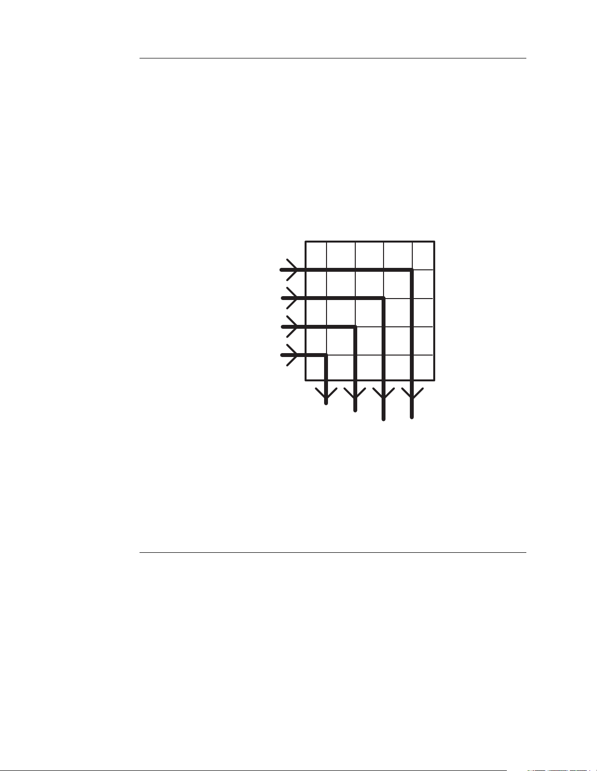
Figure 1.2
Simple Matrix System
™
, Zeus™, and others.
MATRIX
Yo u
Neighbor
Pizza Joint
Gas Station
X
X
Yo u
Neighbor
X
Pizza
Joint
X
Gas
Station
Like the telephone system, matrix systems have other functions and capabilities.
Conferences, call waiting, busy signals, and other features are common to many matrix
intercoms. They are not limited to simple point-to-point communications. Some systems
even allow inter-matrix routing of signals, similar to long distance telephones calls using
trunks between central offices. Having a matrix system with a number of conferences
configured within it (virtual PLs) is very common.
Wireless Systems
Wireless Intercoms encompass all sorts of systems from the most basic pair of “walkie
talkies” to cell phones to dedicated professional full duplex intercom products. The most
basic feature of wireless intercoms is that they are not tethered by wires. (Didn’t think this
was going to be quite that basic, did you?) Seriously, wireless intercom systems are
employed where the limitation of wireless systems which can include fidelity,
interference, lack of range, lack of security (real or perceived), and battery life limitations
are outweighed by the freedom of being cordless. This freedom can be essential in many
applications—try dragging a wired intercom cable into the containment vessel of a nuclear
reactor.
Wireless intercom systems can be designed, installed, configured and operated in PL or
matrix configurations, and may very likely be connected to a hard-wired PL or matrix
2 Handbook of Intercom Systems Engineering
Page 17
intercom system at some point. They can range from as simple as a single pair of units
HeadsetControls
talking to one another, to a system in which 24 or more different portable units are
dynamically switched between conversations.
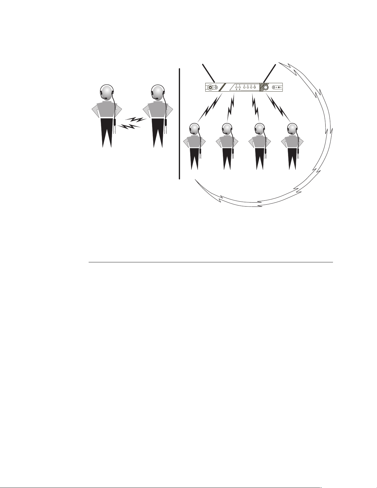
Figure 1.3
Wireless Intercom Examples
Transmit to
Beltpacks
BTR-300
RadioCom
Power
Headset
ExtIntercom AuxAudio
PortableTransmitOn
4
2
1
3
PortableStationConnect
BTR-300
HeadsetControls
Talk
Gain
O/M
PushTwiceto Latch
Volume
Transmit to
Base
TR-300
TR-300 TR-300
TR-300
Mirror Image Pair
Telex TR-500
Base Station with
4 Remotes
Wireless systems will vary tremendously worldwide, due to varying governmental radio
regulations. What is common in America may be illegal in Japan, and may be unsuitable,
for other reasons, in Germany. These units may be referred to by any of the types
mentioned above, but, again, the unifying feature is the freedom from a wire.
Accessories
The fourth and final category is “accessories”. We are giving accessories its own separate
category because of its importance. This book is addressing intercom systems. In all
likelihood, many of the systems you encounter will be an amalgam of the three types
mentioned above. Without “accessories” you cannot have a system, just a bunch of
equipment.
To connect a TW system to a matrix system, a converter is required to change the
combined talk and listen signal from the TW to separate talk and listen signals for the
matrix – a hybrid provides this conversion.
Chapter 1 - Intercoms—An Overview 3
Page 18

Figure 1.4
Example of Interfacing a TW System to a Matrix System
To connect a matrix intercom system to a Two-way radio system, a contact closure may be
required to activate the radio transmitter. A GPI (General Purpose Interface) between the
matrix and the base station of the radio can solve this problem easily.
To do intelligent trunking between matrix systems, across campus or across the country,
the audio and control signals between the matrices could be transported over fixed pairs of
wires. Realistically, however, installing a set of wires between Omaha and Los Angeles
may be out of your budget – so an interface allowing the use of dial-up telephone lines
may be needed. Other possibilities include muxes and demuxes to allow the audio and data
to be carried over an existing corporate Wide Area Network (WAN), or “piggybacked” as
subcarriers on an existing satellite feed.
4 Handbook of Intercom Systems Engineering
Page 19
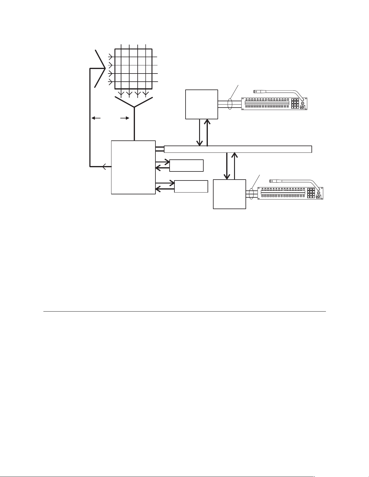
Figure 1.5
Complex Matrix Intercom System
MATRIX
Audio IN,
Audio OUT,
Data
Analog
Audio
Third Party
Terminal
Equipment
LISTEN
FLORTEL2TEL1T1NEWSADTDIFB4PL01RAPRODDIR
Keypanel
PLNUM
AUTO
3
2
1
ISOSUST IFB
PHONE
AUD1ISO2ISO1CHYR
6
5
4
RELAY
E-PANL
COPY
9
8
7
DISPLAY
CLEAR
MULT
CALL
PGM
CLR
0
FUNC
LAN / WAN
Third Party
Terminal
Equipment
Email
System
News
Computers
Third Party
Terminal
Equipment
Audio IN,
Audio OUT,
Data
PLNUM
AUTO
3
2
1
LISTEN
FLORTEL2TEL1T1NEWSADTDIFB4PL01RAPRODDIR
ISOSUST IFB
PHONE
AUD1ISO2ISO1CHYR
6
5
4
RELAY
E-PANL
COPY
9
8
7
DISPLAY
CLEAR
MULT
CALL
PGM
CLR
0
FUNC
Keypanel
In many cases, connection to “the telephone company” is required to allow a reporter to
connect into an intercom from his or her cell phone, or to allow a return program feed to be
fed to a remote location. A telephone interface (TIF) unit provides this connectivity.
The most basic accessory in an Intercom system may be the headset. It may provide
isolation from ambient noise; it may have a noise-canceling microphone to reduce wind
noise, and may have stereo ear pieces to allow program audio and intercom audio to be fed
independently to the right and left ears.
Each of these accessories is vital to creating an intercom system that meets the
communications needs of the users.
Before We Begin
Throughout this book, you will be subjected to the jargon that permeates the intercom
world. In the chapters that follow, you will be presented with definitions specific to the
topic being covered. In many cases, there are common terms that will be applicable to all
these chapters, and so we will present a few definitions to get us started. We have also
provided a comprehensive glossary in the rear of the book.
IFB
Interrupted Fold Back – also referred to as IRF – Interrupted Return Feed. The best way to
explain this is to give an example. A news reporter is on the scene of live accident
coverage. She needs to not only hear what the anchor back at the studio is saying i.e., “So,
Jane, how many chickens were injured when they tried to cross the road during rush
hour?” She also needs to hear instructions from the director back in the studio i.e., “Wrap
it up, 10 seconds.” The IFB function in an intercom system allows a single audio signal to
be sent to Jane, normally containing program audio interrupted by instructions or
information from someone not a part of the program audio.
Chapter 1 - Intercoms—An Overview 5
Page 20

ISO
Camera Isolate – This is not reserved strictly for the domain of cameras anymore. This is
truly an isolate function, not unlike the action at a party of grabbing the arm of a fellow
guest, dragging them off to a corner for a private conversation, and then returning them to
their group. There are instances where it is necessary in an intercom system to establish a
momentary private conversation with someone who may be talking and listening to a
number of other people. The person who needs to interrupt presses a button or key, which
establishes a private two person conversation. Upon releasing the key, the two participants
are returned to whatever conversation(s) they were a part of previously. This was called
Camera Isolate as it first was used to remove an individual camera from a conference to
allow private communications.
Tally
A signal sent for the purpose of indicating status for a particular purpose. The sound of
your telephone ringing can be described as a tally. On an intercom panel with multiple
channels, it can be a visual signal, such as a blinking light, to indicate which station is
calling. It can be used to indicate a particular function is not available due to a conflict –
similar to the busy signal you get when calling the radio station trying to be the tenth caller
and win a year’s supply of cat litter.
The above definitions and many more can be found in the glossary at the back of this
book.
The Rest Of The Book
We have organized this book by the above types of systems – two chapters devoted to PL
Intercoms, two chapters for matrix systems, two chapters for wireless systems, and one
chapter on interfaces, determining systems needs and requirements, technical
requirements for installation, and some real world case studies.
Near the end of the book, we have included references for further information, a glossary,
and a CD full of information on Telex
drawings.
®
Products, technical references, and many system
6 Handbook of Intercom Systems Engineering
Page 21

Introduction
C
HAPTER
2
I
NTRODUCTION TO
I
NTERCOM
C HAPTER
2
P
ARTY
S
-L
YSTEMS
STAN HUBLER
INE
Leading off this chapter, Some Definitions that may help you understand Party-Line
intercoms terms (and buzz-words). Then, a Short History of Party-Line intercoms will be
presented, leading into a discussion of Present Day Systems and Manufacturers. The
System Components and Their Function will explore the main components of these
systems and what they do. Then, How Each System Works shows how these system
components are put together to make a functioning intercom and some examples of the
different systems. Outstanding Features of Each System describes application areas and
where each system is often marketed. Some important Limitations of Each System are
described and a Summary closes this chapter.
Some Definitions
Party-Line (PL) systems / Conference Line Intercom Systems
A Party-Line system allows a group of people to intercommunicate. For example, one
person can talk, while all the others on the bus or channel can hear. When the system is full
duplex, anyone can talk and the rest can hear or interrupt the speaker at any time. The
Party-Line and distributed matrix systems presently sold today are usually full duplex and
are non-blocking, which means that access to the channel is immediate and there is no
busy signal. Conversations on Party-Line systems are, in general, non-private. It is
important to note that both two wire and four wire type systems support the Party-Line
concept.
Two-Wir e
A communications system where the path is the same for both talk and listen. In electrical
pathways there are, in fact, two wires (one path). Two-wire systems can be two-wire
balanced or two-wire unbalanced.
Chapter 2 - Introduction to Party-Line Intercom Systems 7
Page 22

Balanced Line
The balanced line concept reduces noise pickup by outside sources. A balanced two
conductor line carries audio that is differentially driven and balanced to ground.
Full Duplex
This is communication that allows simultaneous two-way conversations, that is, one
person can interrupt the other. In data communications, full duplex permits confirmation
of sent data by the receiving terminal echoing, sending back the same data, or confirming
data.
Decibel (dB)
A derived unit of loudness. The human ear perceives a 10 decibel increase as twice as
loud, and a 10 decibel decrease as half as loud.
Beltpack
A portable headset user station. This station is designed to be worn on a user’s belt, but is
also fastened to the underside of consoles, taped to a structure near the user, or mounted on
a piece of equipment. The headset plugs into the user station, as does the connection to the
rest of the intercom.
Biscuit
Marketing buzz word for a portable speaker station.
Main Station
A multichannel user station. There may be one or more of these stations in a system.
Usually the primary station in a system.
Master Station
A user station where a user station and a system power supply are combined into one
package
Sidetone
In the truest sense, sidetone is a small amount of microphone signal fed back to the
earphone of the individual speaking into the microphone. In a two type user station, the
null balance control is sometimes used to adjust the amount of sidetone the user hears.
This control is sometimes (erroneously) called the sidetone control. Other equipment has
both null balance adjustments and a true sidetone adjustment.
Crosstalk
Unwanted interference caused by audio energy from one line coupling (“leaking”) into
adjacent or nearby lines.
A Short History
Party-Line intercoms were needed early on by television production crews to coordinate
their activities. Some of the activities included on-site sport pickups, entertainment on
stage, and videotaping of shows. The crews included camera operators, audio, lighting,
8 Handbook of Intercom Systems Engineering
Page 23

stage directors, director, assistant director, production assistant, and others. Originally,
these crews shared one intercom channel where the director called the shots. Later, as
intercom developed, additional channels were added so each crew could still listen to the
director, then could switch to their own channels to coordinate activities without conflict
with the director. Party-Line intercom systems were also used by industrial activities to
coordinate manufacturing and testing of large systems such as aircraft.
Early intercom systems (1960-1975) were either homemade or accumulations of telephone
equipment lashed together. Often, the homemade intercoms worked well enough but
lacked the flexibility to expand the system or interface with other systems. The telephone
equipment approach had some flexibility, but performance degraded rapidly as the number
of stations increased above ten user stations.
In the early 1970s, Clear-Com built Party-Line systems for rock-n-roll concerts, and later
for theatrical stage, and eventually for television production. This system was flexible and
expandable, but required one three-conductor microphone cable for each channel. In the
mid 1970s, another company, RTS Systems, designed a system for television production
that had two channels on one three-conductor microphone cable (or one channel on a pair
of wires). This system was even more flexible and expandable with a design that allowed
up to 50 user stations on a single channel. On the East Coast, a company, Chaos, produced
intercoms for the New York and other stages. And, in the Midwest, a company, Telex
Communications, produced a balanced Party-Line system. This system was especially
useful in noisy electrical environments, because it was immune to induced interference.
Other Party-Line systems include systems such as David Clark, which is used for fire
trucks and similar public safety and service crews. And, of course, four wire matrix
systems can emulate Party-Line intercoms.
As Clear-Com
systems of both appeared. They included HME and Production Intercoms for Clear-Com,
and ROH and Anchor Audio’s PortaCom for RTS
®
and RTS™ Systems intercoms became more widely known, compatible
™
. Chaos is similar to Clear-Com,
except it uses a much higher power supply voltage (46 vs. 24 volts). As the markets
expanded, the distinction between theatrical and television production became blurred and
Party-Line systems of all types were used wherever they were needed. So a competitive
atmosphere developed and continues to the present. ROH and HME are no longer in the
wired intercom market.
Present Day Systems and Manufacturers
Note
The three major brands of “two-wire” Party-Line intercoms having the largest worldwide
presence are RTS, Clear-Com, and Telex
Clark, PortaCom, and Production Intercom.
Table 2.1
Brand Name Manufacturer
Audiocom
Chaos Goddard Design Company
Clear-Com Clear-Com Intercom Systems
David Clark David Clark Company, Inc.
PortaCom Anchor Audio, Inc.
Production Intercom Production Intercom, Inc.
RTS
Intercom brand name vs. manufacturer.
®
™
Telex Communications, Inc.
Telex Communications, Inc.
Present day Party-Line intercom systems are mostly distributed amplifier type systems as
opposed to a centralized system where all the headset lines plug into one box (Some David
Clark Systems are of a centralized type). Oh yes, there is a no-amplifier system called a
Chapter 2 - Introduction to Party-Line Intercom Systems 9
Audiocom. Other brands include Chaos, David
Page 24

sound powered system, but we do not discuss it here. Present day Party-Line intercom
systems may be wired or wireless or both.
System Components and Their Function
The system components for most Party-Line intercoms consist of power supplies (or
master stations), user stations (e.g. belt packs, speaker stations, main stations, etc.),
interconnecting cable, headsets, panel microphones, push-to-talk microphones, and a
system termination.
The power supply (which is normally centralized) generates the DC power for the entire
system (with the exception of self powered user stations). The power supply usually
includes system termination for the audio channel, 200 ohms for RTS and Clear-Com, and
300 ohms for Audiocom. This may be as simple as a capacitor and resistor in a series, or,
an electronic termination, which is integrated into the power supply voltage regulator.
The user station connects to the power supply and intercom line. The human user connects
to the user station via a headset or loudspeaker and microphone or some combination. For
a given channel or channels the user stations are connected to each other in parallel.
The interconnecting cable for most intercoms is standard microphone cable with three pin
XLR type connectors. The female XLR connects towards the power supply and the male
XLR plugs into the user station. This polarity was chosen to prevent putting DC power
onto audio microphones which also use this type cable. There are at least two exceptions to
the use of microphone cable: the RTS
unshielded pairs (12 of the 25 pair in a cable). Another exception is where a twisted pair is
the only connection between two points. The RTS
to a twisted pair, while other user stations need adapters of one kind or another, and power
may have to be supplied at either end.
™
TW master stations connect audio with
™
TW user stations can connect directly
The wired systems are of three wiring configurations: 1) separate power, audio, and return
conductors (example: Clear-Com), 2)an audio pair which includes phantom power and a
common (example: Audiocom), and 3) a conductor that contains one channel and power, a
conductor that contains audio with- or without power, and a return (example: RTS
™
TWTW intercom system).
10 Handbook of Intercom Systems Engineering
Page 25

Table 2.2
Clear-Com
Pin # Function
1 Common for Audio, Power, &
2 DC power: 30 volts nominal
3 Unbalanced Audio
Audiocom
Pin # Function
1 Common for Audio, Power, &
2Audio + DC Power
3Audio + DC Power
RTS TW
Pin # Function
1 Common for Audio, Power &
2 Channel 1 Audio + DC Power
3 Channel 2 Audio
Intercom connector wiring by various manufacturers.
Shield
Shield
Shield
The wireless systems usually include an interface to the wired systems. Principal
manufacturers include Telex Communications, Vega (now part of Clear-Com), and HME.
We will go into further detail on wireless systems in a later chapter of this manual.
Wired intercoms are mostly of the distributed amplifier kind. The distributed amplifier is
built into a User Station. User stations come in various packages and are of three kinds:
headset, speaker-microphone, or both. The various packages include a belt pack (worn on
the users belt, and of the headset kind), console mount (headset or speaker-microphone),
rack mount (headset or speaker-microphone), desk mount (portable speaker station), wall
mount (headset or speaker-microphone), and console/rack mount Master Station/Main
Station (details later). The distributed amplifier concept allows each user to adjust his/hers
own listening level. The user station also includes a microphone amplifier, a line
amplifier/buffer, volume control(s), talk switch(es). Some user stations also may have a
Call light, status indicators, and a channel selector. The microphone may be in the headset,
fastened to or plugged into a speaker station, in a handset, or in a push-to-talk hand held
unit.
Belt Pack Headset User Station Functional Description
A typical single channel belt pack headset user station has the following connectors:
Intercom Line (XLR-3) and a Headset Connector (XLR-4).
The station has the following controls:
Microphone ON/OFF (sometimes called a TALK switch), and a headset Volume Control.
It may also have a Call Lamp and a Call Lamp Send button. Examples of this station are an
™
BP318 single channel belt pack, or an Audiocom® BP1002, or a Clear-Com® RS-
RTS
501.
A typical two channel headset belt pack user station adds a channel selector switch to the
above. Examples RTS
™
BP351, Clear-Com® RS-502, Audiocom® BP2002
Chapter 2 - Introduction to Party-Line Intercom Systems 11
Page 26

Alternately, newer units have two talk buttons, two volume controls, and two status
indicators to tell which talk button is engaged. Examples: RTS
®
RS-522-TW, or Audiocom® IC-2B.
Com
™
BP325, BP351, Clear-
Speaker User Station Functional Description
A typical speaker station can function with either a headset or a speaker/microphone. A
power amplifier, a speaker, and a speaker on/off switch are added to the electronics of a
belt pack. In addition, a nulling adjustment is easily accessible. The nulling adjustment
allows for full duplex operation without unwanted feedback. Also added is a connection or
jack for either a panel microphone (rack mount stations) or a push to talk microphone (for
desk mount or portable speaker stations).
Master Stations
The Master Station allows a user to access multiple channels. This allows different crews
to be monitored, cued or updated. If the master station is used for training, again, different
crews may be monitored and guided. These master stations have extra features for special
tasks such as IFB (Interrupted FeedBack) or SA (Stage Announce), relay closures, “hot”
microphones, and microphone kill. Master stations can send and receive call light signals
on any channel. Two examples of the Master station are Clear-Com
channel) and RTS
™
Model 803 (12 channel). Audiocom’s master station is modular and
can be as few as 2 channels or as many as 22 channels. Master stations allow simultaneous
monitoring of any channel, any combination of channels, or all the channels. They can call
or “mic kill” on any given channel. In addition, some master stations can monitor a
program source.
®
Model 912 (12
Wiring Notes
Some Technical Notes About The Stations Above
The stations mentioned above generally are designed for the dynamic microphones in the
headsets to have an impedance of about 150 to 500 ohms. The speaker station panel
electret microphones are designed to have an impedance of 1000 to 2000 ohms and require
1 to 5 volts excitation. And, the push-to-talk microphones have around 500 ohms. This
means the actual input impedance of the station microphone preamplifier will range from
470 ohms to 5000 ohms. The low impedance of 470 ohms minimizes the crosstalk in the
headset cord. The headphone impedances expected range from 50 ohms to 1000 ohms.
The 50 ohm headphones along with suitable headphone amplifiers provide enough SPL
(Sound Pressure Level) to overcome the interference from loud concerts and sports events.
The headphones also need to have an acoustic isolation of 20dB or more to protect the
user. These stations generally have a bridging impedance across the intercom line of
10,000 to 15,000 ohms. A bridging impedance of 10,000 ohms assures that up to 50
stations can be plugged into the systems and the level drop will only be 6dB. The level
drop of 6dB corresponds to the level drop when an extension telephone is picked up on an
existing conversation-noticeable but the telephone is still usable.
1 Clear-Com
connect to the intercom line. Clear-Com also offers the Clear-Com
which has two channels on a 3 pin XLR.
2 Clear-Com
headsets and a male 4 or 5 pin XLR connector on their user stations. However, RTS
uses a male 4 or 5 pin XLR connector on their headsets and a female 4 or 5 pin XLR
connector on their user stations.
®
and Audiocom® two channel stations have 6 pin XLR connectors to
®
and Audiocom® systems use a female 4 or 5 pin XLR connector on their
®
RS-522-TW,
3 In any system, pin 1 and the shell of the XLR connector should NOT be connected
together.
12 Handbook of Intercom Systems Engineering
Page 27

4 The pin out of the headset connectors is as follows:
Four pin XLR
Pin 1 - Microphone common
Pin 2 - Microphone “hot”
Pin 3 - Headphone common
Pin 4 - Headphone “hot”
Five pin XLR
Pin 1 - Microphone common
Pin 2 - Microphone “hot”
Pin 3 - Headphone common
Pin 4 - Left Headphone “hot”
Pin 5 - Right Headphone “hot”
5 Since the power supply has a limited amount of XLR-3 connectors, splitter boxes are
used to expand the system. These boxes have all the connectors wired in parallel.
6 Some user stations have “loop-thru” connectors that allow “daisy chaining” stations
using a single connection to the power supply.
How Each System Works
Note
Drawings at the end of the chapter depict the systems being discussed.
First, please note that although these systems are full duplex and everybody could
theoretically talk at once, this is not at all practical or desirable. The usual operation is the
director or lead person has their microphone enabled all the time, while all other
microphones are switched off. These microphones are switched on only long enough to
supply an answer, make a request, or give data. In some cases, especially in noisy
environments, all microphones are off and only switched on as required. Because the
Party-Line concept has so many signal sources, this operational protocol is the only way
the Party-Line can be effective. And this is the reason for the system “mic kill”
(microphone turn-off) capability, for the situation where a station is unmanned but has its
microphone enabled.
These systems use voltage controlled current sources (or similar electronics) to apply a
signal to the intercom line. All the signals applied are summed and converted to a voltage
at the single termination resistor or electronic impedance. The current sources (or similar
circuits) have output impedances of 10,000 ohms or greater. The loading effect of the
station on the intercom, say in a 200 ohm terminated system is, worst case, 10,000 ohms in
parallel with 200 ohms. This results in a change of the system termination to 196 ohms, a 2
percent change. This, in turn, causes a voltage change of 2 percent or 0.175dB, an
imperceptible change. It takes 20 stations across the line to cause a 3dB change, a
perceptible but not significant change. The volume controls in the user stations easily
adjust for this change. In the “not so” worst-case situation, these systems can work with up
to 75 stations, provided enough DC power is available. The work-around in this case, in
the RTS
™
TW system, is a switch on the power supply which doubles the system
impedance. Then, two power supplies can divide the DC load and are coupled together
with capacitors to end up with the 200 ohm termination and twice the user stations. In the
case of Clear-Com, the system termination is not electronic but a passive resistor. If an
adapter is made, the same trick can be done in a Clear-Com
®
system power supply. In the
case of Audiocom® intercoms, paralleling two power supplies with capacitors would
result in an impedance of 150 ohms which could still be usable in some instances.
Chapter 2 - Introduction to Party-Line Intercom Systems 13
Page 28

System Powering
Systems can be centrally powered with a power supply or they may be individually
powered with “local power” modules, also known as built-in power supplies. The systems
can also be a mixture of central and local power. In the cases of Audiocom
™
RTS
TW systems, the power and signal share the same wire(s). This means, for those
®
systems and
two systems, the power supplies DC source must be ultra low noise/quiet, circa -70dBu or
better. Most systems can work using main powers of 120 or 240 volts AC. Some
individual stations can be powered with 2 or 3 nine volt batteries in series. Venues such as
the Rose Parade may have to use a pair of batteries from the telephone company just to
cross the street. Since this may involve a mile of copper wire, there is no central DC source
that’s going to make it. Out come the nine volt batteries! The RTS
™
TW power supplies
can tolerate only a 5 volt peak-to-peak signal on the powered line. In this system, each
station can generate a maximum 2 volt peak to peak signal, so two stations talking
simultaneously can add up to 4 volts peak to peak. So, there is just 1 volt of headroom.
Clear-Com specifies a range of signal levels of .5 v p-p to a maximum of 4v p-p, but
doesn’t specify the reference (it is probably dBu or dBv). Audiocom
®
intercoms specify
only a nominal level of 1 volt RMS, which is equivalent to 3 v p-p.
Headset User Stations
The microphone preamplifier has a maximum gain in the neighborhood of 53 dB. Many
stations have Automatic Gain Control (AGC), which adjusts the gain according to the
incoming microphone signal. Some stations also have a limiter that prevents overloading
the intercom line. An electronic switch is placed between the microphone preamplifier and
the current source (line driver). This substantially reduces noise on the intercom line. A
hybrid connection is necessary to sort out the talk and listen signals (a two wire to four
wire converter would work best). The listen signal goes from the hybrid to the listen
volume control. The listen volume control drives the headphone amplifier that has a gain
in the range of 30 to 40 dB. For a 50 ohm headset, the headphone amplifier produces
maximum peak sound pressure levels of around 105dB. This is the level needed at
concerts and sporting events (along with 20dB acoustic isolation of the headset). In less
strenuous situations, a handset instead of a headset may be used with these stations. These
stations must have a bridging impedance of 10,000 ohms or higher. The current drains
range from 30 to 65 milliamperes. Most systems have signal levels that range from -15dBu
to 0dBu. In the case of Clear-Com
microphone preamplifier tend to keep the level in the -10dB range. This enhances
intelligibility and compensates for differences between voices and headset microphones.
Usually the headset amplifier has enough gain to make up the differences (by readjusting
the volume control).
®
and RTS™ TW systems, the AGC / limiters in the
Speaker User Stations
Most of these stations can operate in both a speaker/microphone mode and a headset
mode. The difference between a headset only station and the speaker station is that a
speaker amplifier, switching electronics, and a null pot are added. Usually the portable
speaker stations use a push-to-talk microphone, whereas the fixed speaker stations use a
panel or gooseneck microphone. The stations that have microphone and speaker on the
same panel have less available speaker level because of feedback. The push-to-talk
microphone has much better isolation. Speaker stations often have “dimming” or
“ducking” which attenuate the speaker output when the microphone is keyed. This allows
more gain and less feedback. Speaker stations use a very substantial amount of current,
about 120 milliamperes. So, fixed speaker stations are ideally operated with local power,
to prevent overloading the central power supply. Some RTS
and do not use central power.
14 Handbook of Intercom Systems Engineering
™
TW are direct AC powered
Page 29

Master Stations
These are multichannel stations. Some Master Stations are balanced (RTS™ TW Model
802/803) and require an interface (RTS
™
TW Model 862 or 4012) to work with
unbalanced channels. Master Stations can be configured to work with their respective
systems with a minimum of interfacing. Master Stations have many functions which we go
into to detail later.
Cabling
Usually the intercom system’s specifications are based on the use of 22 AWG microphone
cable. Microphone cable of 22 gage measures 3 ohms per 100 feet or about 30 ohms per
1000 feet (round trip resistance). The wire table says 32 ohms per 1000 feet round trip, but
the shield resistance is much lower than the wire resistance. The Audiocom
both wires and the shield to transport DC so the calculations will be different for DC
voltage drop versus distance.
Outstanding Features of Each System
The Audiocom® system is immune to noise and is a lower cost system. It is used in
difficult environments, i.e.: churches, concerts, theaters, and sporting events.
The Clear-Com
available. It is often used for concerts, rock-n-roll tours, and in theaters. It is also used in
remote trucks, uplink trucks, and low budget venues.
The RTS
™
available in most countries world wide. Because the RTS
microphone cable, it is used where many channels are required, such as the Oscar and
Emmy award shows. It is also used for events such as the Superbowl. Most larger TV
trucks carry both a four-wire system and an RTS
interfaced together so the four-wire is used inside the truck and the RTS
outside the truck.
®
system is robust, relatively lower in cost, and rental systems are readily
system is also very robust, reasonable in cost, and rental systems are readily
®
system uses
™
intercom has two channels per
™
Party-Line system. These systems are
™
system is used
In addition to these features, most systems support extra features such as, “microphone
kill” and “call light”. The microphone kill feature allows all microphones in a given
channel to be switched off. In the case of Audiocom and RTS, the signal is an inaudible 24
kilohertz. In the case of Clear-Com, the power is interrupted for a long enough time to
reset the microphones to off.
Call Lights
The Call Light Signal allows user stations to generate and display a visual signal for
attention-getting and cueing purposes. The flashing light of the RTS
systems alerts the crew to put their headsets back on. The steady light of the Clear-Com
system can also be used for this purpose, however, it has another purpose: when the
director holds the call light on, this is a standby signal. When the light goes off, this is the
execute signal (raise/lower the scenery, follow spot on, et cetera). Call signals can also be
used to key 2-way radios, sound alarms, and activate lighting controls. Audiocom
™
systems use an inaudible 20 kilohertz signal for the call signal; Clear-Com
RTS
systems use a DC voltage added to the audio signal. Telex manufactures a call signal
detector / display (Model CIA-1000) which provides both a high visibility light and a relay
closure when a call signal is sent. The CIA-1000 works with RTS
systems. Clear-Com and other manufacturers also provide similar products. The company
VMA supplies a bright strobe lamp that is triggered by the RTS
Chapter 2 - Introduction to Party-Line Intercom Systems 15
™
and Audiocom®
®
and
®
™
TW and Audiocom®
™
system call signal. This
®
Page 30

strobe is powered from the RTS line but only draws 10 milliamperes. It also supplies a
relay closure and a logic signal.
Limitations of Each System
Cable capacitance, resistance, and crosstalk affect all three systems. The longer cables
(over 2000 feet) limit the number of belt packs at the end. A system with cumulative
cables adding up to 10,000 feet will have a reduction in frequency response due to cable
capacitance. Both resistance and capacitance affect crosstalk.
If all you have is a twisted-pair cable, then the RTS
severe coupling with power cables, the Audiocom
Some of the information in this chapter is repeated in the next chapter, but in a different
context.
Summary
(Some Definitions)
1 A Party-Line system allows a group of people to intercommunicate.
2 “Two-wire” means a communications system where the path is the same for talk and
listen.
™
system is most useful. If you have
®
system will help.
3 A balanced line reduces unwanted noise and crosstalk pickup.
4 A full duplex intercom allows simultaneous two-way conversations.
5 The human ear perceives a 10 decibel increase as twice as loud.
6 A belt pack is a user station designed to be worn on a user’s belt.
7 A main station is a multichannel user station.
8 A master station combines a user station and a power supply.
9 Sidetone is a small amount of microphone signal fed back to the user’s ear.
10 Crosstalk is unwanted interference.
(A Short History)
1 Television, theatrical, and concert production crews need Party-Line intercoms.
Party-Line intercoms are also used for training and for industrial crews.
2 Early intercoms were inflexible and limited to small groups of users and sometimes
short distances.
3 In the 1970s, fresh new designs were the beginning of the modern Party-Line
intercoms we use today.
(Present Day Systems and Manufacturers)
1 Principal “two-wire” Party-Line brand names today are Audiocom, Clear-Com, and
RTS. Other brand names are Chaos, David Clark, PortaCom, and Production
Intercom.
2 With the exception of David Clark, present day Party-Line intercoms are the
distributed amplifier type.
16 Handbook of Intercom Systems Engineering
Page 31

3 This format allows louder and clearer communication. Party-Line intercoms can be
wired or wireless or both.
(System Components and Their Function)
1 The system components for most Party-Line intercoms consist of power supplies (or
main stations), user stations, interconnecting cable, headsets, panel microphones,
push-to-talk microphones, and a system termination.
2 The power supply (normally centralized) generates DC power for the entire system
(exception: self powered user stations).
3 The power supply usually includes the system termination.
4 User stations connect to the power supply and intercom line(s).
5 For a given channel, user stations are connected in parallel.
6 The interconnecting cable for most intercoms is standard microphone cable.
7 For the major three intercoms (and their clones) there are three wiring schemes.
8 Wireless intercoms usually include and interface to the wired systems.
9 Wired intercoms are mostly of the distributed amplifier kind.
10 Distributing the amplifiers allows for better performance and more features.
11 A single channel belt pack has an intercom line connector, a headset connector,
volume control, and a talk or microphone on/off switch. A two-channel belt pack
adds a channel selector or two talk switches and two volume controls.
12 A speaker station usually can be a headset or a speaker station.
13 Speaker stations add a power amplifier, speaker, and speaker on/off switching to the
headset station electronics.
14 Master Stations are multichannel and allow a director or lead person to have separate
conversations with various crews in any combination. Master Stations often have
many additional functions.
15 Dynamic microphones used with intercom stations usually range from 150 ohms to
500 ohms impedance. Electret microphones range from 1000 to 2000 ohms
impedance and require 1 to 5 volts DC excitation voltage.
16 Headphones range in impedance from 50 to 1000 ohms. For concerts and athletic
contests, 50 ohm headsets work better. The headphones should also have at least
20dB acoustic isolation for concerts and athletic contests.
17 The bridging impedance of each station should be 10,000 ohms or greater.
18 Since the power supply has a limited number of connectors, splitter boxes are needed
to expand the number of user stations in a system.
19 Both male and female XLR-4 connectors are used to connect the headset with the
user station. XLR-5 connectors are used for binaural headsets.
20 Some stations have loop through connectors to allow daisy chaining of stations.
(How Each System Works)
1 The stations use a voltage controller current source or similar electronics to apply
signal to the intercom line, yet exhibit a bridging impedance of 10,000 ohms or
greater.
Chapter 2 - Introduction to Party-Line Intercom Systems 17
Page 32

2 Systems can be powered from a central power supply or local powered modules.
Using local power modules allows more stations to be on the system.
3 If a station is too far away to get enough DC power, batteries can be used as a work-
around.
4 Headset User Stations have a microphone preamplifier with a maximum gain around
53dB. Many stations have an AGC (Automatic Gain Control) that adjust the gain to
the incoming microphone signal level. Some stations also have a limiter to prevent
overload to the intercom line.
5 Headset User Stations have a hybrid function to convert the two-wire signal to a four-
wire signal. The listen part of that signal is sent to the volume control and then to the
headphone amplifier.
6 Portable Speaker User Stations usually have a push-to-talk microphone that gives
good speaker to microphone isolation. Fixed stations have a panel microphone.
7 The cabling used in these intercom systems is usually called out as 22 AWG. Use of
a smaller diameter wire such as 24 AWG shortens maximum distances and the
number of user stations on a cable.
(Outstanding Features of Each System)
1 The Audiocom
difficult environments, i.e.: churches, concerts, theaters, and athletic contests.
2 The Clear-Com
often used for rock and roll tours, other concerts, in theaters, and in smaller outside
broadcast trucks.
3 The RTS
almost worldwide. Used every place, but especially where many multiple channels
are needed such as the Oscar ceremony.
4 Most larger TV trucks carry both a four-wire system and an interfaced RTS
system.
®
system is immune to noise and is a lower cost system. It is used in
®
system is robust, relatively low cost, available as a rental. It is
™
TW system is very robust, reasonable in cost, rental systems are available
™
TW
5 Call Lights and “mic kill” features are in all three major brands. The Call Light
signal can be used to operate relays, radio keying, and warning lamps.
(Limitations of Each System)
1 Audiocom
2 The RTS
3 All systems that use microphone cable are subject to distance limitations, as well as
the number of stations per cable.
4 Clear-Com
interference (practically speaking, rarely a problem).
®
and Clear-Com® systems require three wires for a single channel.
™
TW system may have crosstalk (but this is rarely a complaint).
®
systems and RTS™ TW system have less immunity to outside
18 Handbook of Intercom Systems Engineering
Page 33

Figure 2.1
Audiocom® intercom concept.
Figure 2.2
Clear-Com® intercom concept.
Chapter 2 - Introduction to Party-Line Intercom Systems 19
Page 34

Figure 2.3
RTS™ TW intercom concept.
Figure 2.4
RTS™ TW user station block diagram.
20 Handbook of Intercom Systems Engineering
Page 35

Overview
C
HAPTER
3
D
ESIGN OF
I
NTERCOM
C HAPTER
3
P
ARTY
S
-L
INE
YSTEMS
STAN HUBLER
In this chapter, designing a system based on your needs is first approached by Defining
And Meeting Your Needs. This topic is designed to help you choose or at least
understand the system. IFB is described in The IFB System (One Way Communications
System). Then Connecting (Interfacing) to Other Communications Systems discusses
real world solutions to interfacing these systems. The Some Practical Considerations
section discusses real world environments and some work-arounds. A Summary closes
this chapter.
Defining And Meeting Your Needs
Your needs could include buying, renting, assembling or expanding a system. Application
Block Diagrams are a good starting place to define a system. In this section, block
diagrams of applications in each of the three leading systems will be shown and discussed.
These diagrams will range from relatively simple to complex systems. One of these block
diagrams could be close to what you need to know, give or take a station or so. If you
make a copy of the diagram and mark it up, this could define your system.
Disclaimer
The block diagrams are for instructional purposes, and though every effort has been for
accuracy, the manufacturers offerings are often changing. It pays to double check with the
manufacturer or rental house to verify the exact system available before buying or renting.
Application 1 Generic Single Channel Systems
The first applications are generic single channel systems, see Fig.1.3. They consist of a
power supply, belt packs, headsets, splitter boxes, and microphone cables. These are
systems that could be used in a small television studio production, a small outside
television field production, or an industrial test of a large system. Depending on the detail
of the block diagram, you may be able to compile an equipment list from this diagram.
Chapter 3 - Design of Party-Line Intercom Systems 21
Page 36

Audiocom Party-Line Intercom Equipment Listing #1
Figure 3.1
Generic single channel Audiocom® system.
Power Supply: PS2001L
Splitters: TW5W
Belt Packs, Single Channel: BP1002
Headsets: Leader Person: Single Muff PH-1; rest of crew: Double Muff PH-2
Cables: Standard Microphone Cables with XLR-3 connectors
The first block diagram, Figure 3-1 shows a simple single channel Audiocom intercom
system. We start with a 2-channel PS2001L phantom power supply, two TW5W splitter
boxes, two strings of three each single channel BP1002 belt packs, one PH-2 single muff
headset and five PH-2 double muff headsets.
Note
A switch on the PS2001L power supply allows both channels to be combined for one large
Party-Line.
22 Handbook of Intercom Systems Engineering
Page 37

Clear-Com Party-Line Intercom Equipment Listing #1
Figure 3.2
Generic single channel Clear-Com® system.
Power Supply: PK-5
Splitters: TWC-10A
Belt Packs, Single Channel: RS501
Headsets: Leader Person: Single Muff CC-95; rest of crew: Double Muff CC-260
Cables: Standard Microphone Cables with XLR-3 connectors.
Chapter 3 - Design of Party-Line Intercom Systems 23
Page 38

RTS TW Party-Line Intercom Equipment Listing #1
Figure 3.3
Generic single channel RTS™ TW system.
Power Supply: PS15
Splitters: TW5W
Belt Packs, Single Channel BP319
Headsets: Leader Person: Single Muff PH-1R; rest of crew: Double Muff PH-2R
Cables: Standard Microphone Cables with XLR-3 connectors.
Application 2 Two-Channel System: TV, School, Cable
The second application is a two-channel system for a small TV operation (Studio or
Truck), school or cable access. The Audiocom
two 3-conductor microphone cables between director, switcher, video, and graphics. The
™
RTS
24 Handbook of Intercom Systems Engineering
TW system only requires a single microphone cable for all hook-ups.
®
and Clear-Com® systems will require
Page 39

Figure 3.4
Small TV operation.
Note
Audiocom Party-Line Equipment Listing #2
Power Supply: PS2001L (Rack Mount, 1RU)
Director’s Station: US2002 (Rack Mount, 1RU)
Video: WM2000 (Wall Mount)
Graphics: WM2000 (Wall Mount)
Cameras and Floor Manager: BP1002 (Belt Packs)
Headsets Director, Switcher, Floor Manager, Video, Graphics: Single Muff PH1
Headsets: Cameras: Double Muff PH2
Splitter: TW5W IFBs: IFB-1000
Earphones (Earsets): CES-1
Cables: Standard Microphone Cables with XLR-3 connectors. One cable per channel.
/2 indicates two microphone cables & /1 indicates one microphone cable.
Clear-Com Party-Line Equipment Listing #2
Power Supply: PS22 Rack Mount with RK-101 kit (2RU)
Director’s Station: RM220 (Rack Mount, 1RU)
Switcher’s Station: RM220 (Rack Mount, 1RU
Video: MR202 Wall Mount (2-gang box)
Graphics: MR202 Wall Mount (2 gang box)
Cameras and Floor Managers: RS-501 (Belt Packs)
Headsets Director, Floor Managers, Video, Graphics: Single Muff CC40
Chapter 3 - Design of Party-Line Intercom Systems 25
Page 40

Note
Headsets: Cameras: Double Muff CC60
IFBs: TR-50 (Includes earset)
Splitter: TWC-10A
Cables: Standard Microphone Cables with XLR-3 connectors. One cable per channel.
/2 indicates two microphone cables required.
RTS TW Party-Line Equipment Listing #2
Power Supply: PS31 Rack Mount (2RU)
Director’s Station: MCE325 (Modular Mount: Rack/Desk/Console (1RU)
Switcher’s Station MRT327 (Modular Mount: Rack/Desk/Console (1RU)
Video: WM300L: Wall Mount (2 gang box)
Graphics: WM300 Wall Mount (2 gang box)
Cameras and Floor Managers: BP351 Belt Packs
Headsets Director, Floor Managers, Video, Graphics: Single Muff: PH-1R
Headsets Cameras: PH-2R
IFB’s: IFB325 Earsets: CES-1
Splitter: TW5W Cables:
Note
Standard Microphone Cables with XLR-3 connectors. One cable per two channels.
Ignore /2, both channels are in one microphone cable.
Application 3 Theater System
Figure 3.5
Theater application.
The third application is a theater application, see Figure 3-5. A two-channel system is used
in this application. Channel A connects the crew together and channel B is used by the
stage manager to cue the actors. This is done using three wall mount or portable speaker
stations. For all three systems, only standard microphone cable is required. In the case of
the RTS
™
TW system, Channel B is available to the crew, but except for rehearsals or set-
up they would stay on Channel A.
26 Handbook of Intercom Systems Engineering
Page 41

Audiocom Party-Line Equipment Listing #3
Power Supply: PS2001L (Rack Mount, 1RU)
Stage Manager’s Station: US2002 (Rack Mount, 1RU)
Dressing Rooms and Green Room: SS1002 (Single channel wall mount station; if a
portable speaker station is desired, add an S, U, or P box).
Crew: BP1002 (Single Channel Belt Packs)
Headset: Stage Manager Single Muff PH1
Headsets: Crew: PH2
Cables: Standard Microphone Cables with XLR-3 connectors. One cable per channel.
Clear-Com Party-Line Equipment Listing #3
Power Supply: PS22 Rack Mount with RK-101 kit (2RU)
Stage Manager’s Station: RM220 (Rack Mount, 1RU)
Dressing Rooms and Green Room: KB-212 (Single channel wall mount speaker station, if
a portable speaker station is desired, add a V-Box portable enclosure.)
Crew RS-501 (Single Channel Belt Packs)
Headset: Stage Manager: Single Muff CC40
Headsets: Crew: Double Muff CC60
Cables: Standard Microphone Cables with XLR-3 connectors. One cable per channel.
RTS TW Party-Line Equipment Listing #3
Power Supply: PS31 Rack Mount (2RU).
Floor Manager’s Station: MRT327 (Modular Mount: Rack/Desk/Console (1RU).
Dressing Rooms and Green Room: SS1002 (Single channel wall mount speaker station).
Crew: BP319 Belt Packs (Set to work on Channel A).
Headset: Stage Manager: Single Muff: PH-1R.
Headsets: Crew: PH-2R.
Cables: Standard Microphone Cables with XLR-3 connectors. One cable per two
channels.
Chapter 3 - Design of Party-Line Intercom Systems 27
Page 42

Application 4 Training Systems
Audiocom
Figure 3.6
Audiocom® based training intercom system.
The training system consists of an instructor and multiple two-student crews.
In the case of Audiocom, each of the six two-student groups are independently addressable
by the instructor. When the student groups are not talking to the instructor, each twostudent group can have semi-private conversations. The call light tells the instructor which
group is paging. The balanced Audiocom system is ideal in hostile electrical noise
environments.
Power Supplies: SPS2001 and PS4001.
Instructor’s Station: US2002 and Expansion Station.
Students’ Stations: BP1002 Single Channel Belt Packs.
Instructor’s Headset: PH-1, Single muff headset.
Students’ Headsets: PH-2, Double muff headsets.
Cables: Standard Microphone Cables with XLR-3 connectors. One cable per channel.
28 Handbook of Intercom Systems Engineering
Page 43

Clear-Com
Figure 3.7
Clear-Com® based training intercom system.
It just happens that the Clear-Com® system is the simplest for this application, since the
Master Station, MS-812A has the three pin XLR connectors for 12 channels on the rear
panel. The MS-812 has several configurations, and will have to be specified for this
application (No IFB, 12 Clear-Com standard PL channels).
Power Supply: PS-464.
Instructor’s Station: MS812A.
Students’ Stations: Single Channel Belt Packs RS-501.
Instructor’s Headset: Single Muff CC-95.
Students Headsets: CC-250.
Cables: Standard Microphone Cables with XLR-3 connectors. One cable per channel.
Chapter 3 - Design of Party-Line Intercom Systems 29
Page 44

RTS™ TW
Figure 3.8
RTS™TW based training intercom system.
The RTS™ TW system for this application is the next simplest, and has added features.
The student crews can have completely private conversations, yet are still reachable via
the call light paging system. Each BP325 belt pack can be configured to accept an
individual program source (but the loop-through is lost and the two students line
connection will be through a simple one to two splitter). The program source is often a
training audio/video tape, along with a monitoring computer tests the reaction time and
correctness of the students reaction.
30 Handbook of Intercom Systems Engineering
Page 45

Application 5 Medium System for Television
Figure 3.9
Medium intercom system for television.
This shows an RTS™ TW large 12-channel system. This is a system that is in medium
trucks that haven’t yet switched over to a combination matrix and Party-Line system. This
system consists of five Model 803 Master Stations, four PS31 Power Supplies, one
SAP1626 Source Assign Panel, a BOP220 Break Out Panel, a VIE Video Isolate Panel, a
four belt pack Telex BTR600 Wireless Intercom, and various belt pack and other user
station. Also are interfaces to a telephone and a satellite communication link. Many trucks
have a similarly configured Clear-Com
®
system. The Master Stations are usually for: the
Director, Assistant Director, Lighting Director, Audio Mixer and Video operator (the one
with the VCP6A isolate panel. No IFB (Interrupted FeedBack) is shown in Figure 3-9, but
an IFB system is easily married to the Master Stations. A large RTS
™
IFB add-on is
shown in Figure 3-10. Note that Model 4020 is now Model 4030. Similar IFB systems are
available from Clear-Com and Audiocom. The Control Station connects to the “Hot Mic”
Chapter 3 - Design of Party-Line Intercom Systems 31
Page 46

output of a Master Station or User Station with a “Hot Mic” output. The IFB electronics
receives its program audio from the audio mixer board.
The IFB System (One Way Communications System)
IFB is a television acronym for Interrupted FeedBack, Interrupted FoldBack, Interrupted
Return Feed (IRF). An IFB system permits a director or producer to talk to the talent,
typically an “on air” announcer, newscaster, or sportscaster. Normally the talent hears the
broadcast program audio. When the director or producer activates the IFB, the program
audio is replaced by the director’s or producer’s voice. Sometimes the program audio
continues in the other ear, sometimes the program audio is reduced instead of completely
removed.
How an IFB Works
Those in control positions (the director, producer, or assistant director for example)
control the interrupt and or announce functions via control stations. Those in receive
positions (on-air talent, floor managers, studio or field crew, audience, talent and crew in
remote locations) are on the receiving end of the user station feed or on the actual user
stations (talent electronics or talent station) via headphones, headsets, earphones, and / or
loudspeakers. In the middle, the central electronics unit provides all the necessary inputs
and outputs, processing, switching, and power distribution.
Note
Studio and Some Field Applications
Model numbers of the different parts of the IFB are as follows:
Control Panel
Audiocom
Models 4001, 4002, 4003
IFB Electronics
Audiocom
4010
Talent Receiver
Audiocom
Earset
Audiocom: CES-1; Clear-Com: (part of Model TR50); RTS
In non-sports activities, the talent normally uses only the interrupt output (mono) of a
Talent User Station. The earphone is hidden behind the talent’s back; a plastic tube runs
from the earphone to the talent’s ear.
®
: Built into US2002, ES4000A. Clear-Com: MA-4, AX-4. RTS™ TW:
®
: Built into US2002, ES4000A; Clear-Com: PIC4000B; RTS™ TW: Model
®
: IFB1000; Clear-Com: TR-50; RTS™ TW: Model 4030
™
TW: CES-1
Field Application, Sports
In the sports broadcasting or sports communication field, the talent uses a noise resistant
headset. The microphone on the headset is the “air” microphone; the headphone is double
muff, stereo. The talent is plugged into the stereo output of (for example) the Model 4030
Talent Receiver User Station. At the IFB Control Station, each talent’s name is marked on
a strip of tape pasted adjacent to the push buttons.
In stadium sports, there is usually little problem in getting a microphone cable from the
IFB Electronics to the Talent Receiver. In the case of golf, auto racing, and sports venues
over an extended area, the distances may be too great. In this case, a four wire circuit can
be run to the talent location and adapted to the connector on the Talent Receiver.
32 Handbook of Intercom Systems Engineering
Page 47

In some more extreme cases, only a single pair of wires may be available. In this case, plug
the talent’s stereo headset into the stereo connection on the talent receiver, then connect
the high side of the pair to pins 2 and 3 of the XLR3 connector and the low side to pin 1
(pseudo-stereo mode). This will give a mono feed with each ear individually adjustable
and both ears interrupted.
For runs of two miles of number 22 gage twisted pair, at least one talent receiver station
should be operable. For a run of one mile, two talent stations should be operable.
Some users have increased the number of talent stations by using higher impedance (300
ohms) headsets. In the case of auto racing and similar loud environment situations, low
impedance noise isolating headsets will be necessary to overcome the volume and amount
of sound. It may be necessary to use a four wire circuit to connect up each talent station,
paralleling the pairs, and running the talent receiver in pseudo-stereo mode, using only the
interrupt (“wet”) output of the IFB electronics.
Field Application, ENG (Electronic News Gathering)
In this case, the earphone is again hidden as in the studio case above. If the talent has to
carry on a conversation with other talent at the studio and other venues, the program feed
should be a mix minus feed. The mix minus feed will allow the talent to hear the other
talents loud enough without hearing their own self too loud.
Connecting (Interfacing) to Other Communications Systems
What is interfacing? Interfacing is either:
1 The interconnection of two normally separate communications systems into one
system.
-OR-
2 The connection of a communications station or device that is not directly compatible
within a system.
To accomplish this, voice and data information is adjusted and then transmitted to the
other system. The adjustments include level translation, impedance compensation, mode
translation, and compensation for parameters of each system.
Some examples are:
1 System to system: connection of a four-wire matrix system installed on a large mobile
unit to two-wire belt packs outside of the mobile unit.
2 System to terminal: connection of a camera with a built-in intercom to an intercom
system, or connection of a radio transceiver into an intercom system.
Why is there interfacing, operationally? From an operations point of view:
1 An operation requires a larger collection of personnel and equipment than normal.
2 A mobile unit is used with a permanent installation to conduct an operation.
3 Coordination between personnel / equipment is required at a remote location.
4 A special part of the operation requires communication with an odd system or terminal.
5 A redundant “backup” path is required.
Why is there interfacing, technically? There are system to system, system to terminal or,
system to device differences.
Chapter 3 - Design of Party-Line Intercom Systems 33
Page 48

Some of these are:
1 Mode differences. There are several not directly compatible modes of operation: two
wire mode, four wire mode, full duplex mode, half duplex mode, simplex mode.
Examples: the TW System is two-wire full duplex, the ADAM
™
matrix is four-wire
full duplex, the telephone is two wire full duplex except some long distance calls are
half duplex (both people cannot talk at once), a walkie talkie is simplex, AudioCom is
two-wire full duplex, Clear-Com is two-wire full duplex, office intercoms are often
simplex operation.
2 Level and Impedance differences. System voltage levels range from - 40 dBu to + 21
dBu with peaks to +28 dBu (where 0 dBu = 0.7746 volts). See Table 3.1, for typical
ranges.
Table 3.1
Typical system impedances and ranges.
Intercom or
Audio System
Telephone 600 to 900 -15 -40 to 0
Old Clear-Com 200, 10k -30 -45 to -15
New Clear-Com 200, 10k -14 -14 to +5
Audiocom 300, 10k 0 -8 to +1
™
TW 200, 10k -10 -10 to -1
RTS
Recording Studio 600, 10k +4 -6 to +24
Nominal
Impedance
(Ohms)
Nominal
Level
(dBu)
Level
Range
(dBu)
There are different modes of intercom operating modes because each mode offers a
different advantage for different needs and situations. For example, two-wire is quick and
easy to hook up, while four-wire is easier to interface to other systems.
A Typical Interfacing Problem
A television camera uses a triax cable to connect the camera to the rest of the electronic
system because a triax cable allows operation over longer distances with more consistent
quality. This is because the triax cable uses radio frequencies to transmit information both
ways on the cable. This is, in effect, four-wire (two path) communication. The following
implementations often need interfacing:
1 Television camera intercoms to intercom systems.
2 Two-wire systems to four-wire systems.
3 Full duplex systems to simplex systems.
4 When transmission medias change.
Interfacing Issues
There are three tasks to interfacing:
1 Mode Conversion.
2 Level Problems.
3 Signal / Data Conversion.
34 Handbook of Intercom Systems Engineering
Page 49

Modes
The following modes exist in intercom systems:
M2) Two-Wire.
M4) Four-Wire.
The following sub-modes are considered for two-wire and four-wire:
M2F) Two-Wire, Full Duplex.
M2H) Two-Wire, Simplex.
M4F) Four-Wire, Full Duplex.
M4H) Four-Wire, Simplex.
Level Problems
One problem in interfacing from two-wire to two-wire is caused by the 2 wire systems’
use of 2 to 4 wire hybrids. Interfacing requires conversion from two-wire to four-wire
twice to allow level adjustments to and from systems. The quality of the two-wire to fourwire hybrid limits the amount of make-up gain available to match levels in one system or
the other.
Another problem with interfacing is that level adjustment is difficult when interfacing
from a limiter controlled system, such as the TW Intercom System, to a non-limiter
controlled system, such as some two or four wire systems. The reason for the difficulty is
that the perceived loudness is greater on the TW System and much less on the non-limiter
controlled system. This difference can be improved or eliminated depending on two
limiting factors: 1) the headroom of the electronics involved, and 2) the quality of any twowire to four-wire hybrids in the path. Interfacing from two-wire to two-wire systems is the
most difficult. Interfacing from two-wire to four-wire is easier, and interfacing from fourwire to four-wire is the easiest. The problem in two-wire / two-wire interfacing is getting
the levels right and preventing oscillations.
The level of the TW and 800 Series conference intercom systems ranges from -10 dBu to
0 dBu, with an average value of - 6 dBu, and is limiter controlled.
Some other systems are listed in Table 3-2. The objective is to convert the modes and to
adjust the levels.
Signal / Data Conversion
Call Light
Some intercom systems use a “Call Light” signal to illuminate lights in individual stations.
This signal may be a 20 kHz tone, a DC level, or a digital logic level. An interfacing
device may handle the method conversion to carry the call light signal.
Data
Other systems have data flow via various methods including: contact closure, logic level,
RS485 bus, RS422 bus, and RS232 bus. The handling of the RSxxx signals is done best on
a case-by-case basis. At this point, system-to-system communications is done via RS232
communications by wire, fiber optic, or telephone lines via modem. Some system-tosystem communication is accomplished through user specified hardware imbedded in
special products.
Some Master Stations have an RS232/485 connection that allows control of the station
over a terminal or another computer.
Chapter 3 - Design of Party-Line Intercom Systems 35
Page 50

Interfacing Practice
Interfacing Television Camera Intercom Systems to TW Systems
General Camera Configuration Information for Television Cameras (except ENG
units)
Television cameras used in broadcast and industry usually have two parts: a camera head
and a camera control unit (CCU). The camera head assembly usually contains the lens
equipment, camera electronics, and triax adapter (if used). The CCU contains additional
electronics for processing video, the other end of the triax adapter, an interface for
microphone audio, and the intercom interface. The intercom interface usually incorporates
switches and electronics so that the intercom can be two-wire or four-wire.
The Problems in Interfacing to Cameras
There are two problem areas in television camera intercoms:
1 The electronics in the camera head.
2 The intercom interfacing electronics at the CCU.
Some possible problems with the camera head intercom electronics are as follows:
• Inadequate headphone drive (Not loud enough for athletic contests and studio
shows)
• No limiter in the microphone preamplifier (level variations are too much)
• The headphone and the microphone share a common circuit return conductor
(headphones oscillate when volume is turned up)
• The Triax Adapter / electronics does not give the camera intercom enough
headroom, so there is a trade-off between signal clipping and signal to noise
ratio.
• The microphone on/off switch does not disconnect the microphone preamplifier
thus adding noise to the system.
• Some possible problems with the CCU intercom interface electronics are:
• An earth ground is applied to the wiring usually in two-wire mode (causes hum
loops in the system)
• The four-wire input to the camera is not bridging impedance
• The two wire “RTS0153 Systems compatible” interface loads the line
• No safety capacitors are installed in the CCU, thus causing burnt transformers if
connected to the intercom line
Alternatives for Interfacing to Television Cameras
1 Bypass the camera, tape a microphone cable to the camera cable, and plug a TW belt
pack in at the end.
2 Use the existing camera intercom, interface it to the TW system with a Model SSA324
or SSA424 interface (if camera intercom is four-wire).
3 In multi-core connected cameras, use the camera wiring to allow a TW belt pack to be
plugged into the camera head. This allows the camera operator to use a portable User
Station mounted on his belt or attached to the camera body. (
Note:
36 Handbook of Intercom Systems Engineering
This requires significant modification to the camera head and CCU)
Page 51

Table 3.2
Intercom comparisons.
Intercom
Type
TW 200 50 to 400 Un-Bal two-wire 5 0 to -10
TELCO 600 600 to 900 Bal two-wire 1 0 to -10
Two-Wire 150 to 200 100 to 1k Un-Bal two-wire 0.7 -10 to -20
Four-Wire 600 600 to 10k Bal four-wire 7 +8
Carbon Mic 150* 4 to 150 Un-Bal two-wire 2 0 to -30
Nominal
Impedance
(Ohms)
Impedance
Range
(Ohms)
TELCO = Telephone-lines in two-wire mode
Two-wire = Clear-Com, ROH, HME, R-Columbia, Protech, Theatre Techniques, Telex**,
some television cameras
Four Wire = RTS
™
ADAM™ intercom, Philip Drake, Link, McCurdy, Ward Beck, ADM,
Farrtronics, PESA, Audix, Datatronics, all triax television cameras, some multi-core
television cameras, Radio-telephones, Telephone-Line circuits, Wireless Intercom systems
Carbon Mic Interphone = RCA, Daven, Video Aids, General Electric, Colorado Video,
many low-cost television camera intercoms
* Per Station
** Telex(r) Phase 2 = 300 ohm, 5 mW balanced line.
Some Practical Considerations
Output
Type Mode
Estimated
Peak TX
Power (mW)
TX/RX
Levels
(dBu)
Headset Cable Lengths
The dynamic (low level) headset cable carries signal levels that differ by as much as 34 dB
+ 52 dB = 86 dB. Ordinarily, there are three types of unwanted coupling possibilities:
resistive (through a common ground), capacitive and inductive. Since separate grounds are
carried back to the microphone preamplifier and headphone amplifier, the common ground
resistive coupling is, in this design, negligible. The capacitive coupling can be made nonsignificant by a 100% shield in the cable. The inductive coupling mode dominates in this
design, and can be offset in several ways:
• The distance between the microphone and headphone pairs can be increased, while the
mutual inductive coupling is decreased by the use of “ribbed” cable (two cables molded
together side-by-side).
• Both the microphone cables and the headphone cables can each be tightly twisted.
• Two or four separate cables can be run. A balancing transformer on the microphone
circuit may be used. Estimated, Safe Operating Distances are as follows:
• Single cable, two shielded twisted pair: 10 feet.
• Dual ribbed cable, two shielded twisted pair: 30 feet.
• Separate cables, shielded twisted pair in each: 50 feet and more.
• Balanced microphone input: up to 100 feet depending on cable used.
Chapter 3 - Design of Party-Line Intercom Systems 37
Page 52

Headphone Impedances
Low impedance headphones are louder, causing the user station to draw more current from
its power source. High impedance headphones are not as loud, drawing less current. Many
user stations have a headphone impedance range from 25 - 600 ohms.
Headphones up to 2,000 ohms will function but greatly reduced levels. In a double muff
headset such as a Beyer DT-109, there are two 50 ohm headphones connected in parallel
resulting in an impedance of 25 ohms.
Wiring Practices/Workmanship Standards
The two most significant wiring practice/workmanship problems are as follows:
1 Unintentional grounding, phase reversals (channel reversing) and power reversal. Cable
shields must not touch connector shells or be tied to the connector shell lug. Cables
(especially the vinyl insulated type) must not be pulled tight around sharp edges.
2 Line noise due to an intermittent connection:
Poor solder joint.
Corroded connector.
Loose screw terminal.
An non-insulated cable shield touching the metal shell of the connector.
Portable user stations should not arbitrarily be taped or fastened to metal structures.
Grounding the case of the user station to an arbitrary structure may introduce large noise
voltages due to local ground currents or due to the completion of a “ground loop antenna”.
Phase reversals are most common with portable microphone cable that has not been
checked with a standard cable tester after fabrication or repair.
DC power reversals are usually not harmful to user stations since there is normally a
protective diode in the circuit. The station simply doesn’t work. Remember: negative is
ground in this system.
Always clear all earth grounds from the RTS™ TW System circuit return ground.
The only ground should be the 22,000 ohm resistor in the power supply.
Unbalanced vs. Balanced
Intercom systems such as the TW System, in the standard, unbalanced configuration have
been operated at distances of up to two miles with acceptable system noise levels. Routing
the intercom cables along the same ductways and pathways as the main power cabling can
increase the noise and hum levels in the system.
If intercom cables have to be routed in this manner at distances over 300 meters (1,000 ft.),
a balanced conversion should be made.
Alternatively, the entire system can be operated in an optional balanced mode and be
powered at each station with the “local power” option. This is sometimes called “dry line,
balanced” operation.
Extended Range On Part Or All Of The System
If a station is locally powered, operational range can be extended up to five miles, using
two transformers to step up the line impedance to 800 ohms (for lower losses). When the
users station has the four wire / 800 ohm option installed, operation is possible up to 20
miles along Telco dry pairs. Operation over longer distances (3000 miles) is possible using
dial up or minimum loss dry lines and the TW series of interfaces.
38 Handbook of Intercom Systems Engineering
Page 53

Cable Considerations
Crosstalk
Use shielded cable to interconnect user stations in areas of possible electrical interference,
(areas such as those near: digital equipment, high current primary power conductors
“power outlets”, transformers, transmitters, and lighting dimmers. Do not run TW
Intercom System cables along the same ductways and pathways as these cables.
Standard wire size for the an intercom system interconnection is #22 gauge shielded cable,
such as Belden 8761, 8723, 9406.
In permanent installations, to reduce both capacitive and resistive crosstalk and to afford a
degree of RF and electrostatic shielding use a cable that has a shielded twisted pair for
each channel, such as Belden 8723. Each pair consists of a conductor for the channel, a
conductor for circuit ground return and shield around the two conductors. The shield is
accessed via a drain conductor. This drain conductor and the shield can augment the circuit
grounds and thus lower the ground resistance. Do not tie the shield to chassis, earth, or
connector shell ground.
Crosstalk Through A Common Circuit Ground
Since, in the unbalanced version of a TW intercom, all channels share a common circuit
ground return, crosstalk due to common ground resistance can occur. This crosstalk is
proportional to the ratio of the common ground resistance to the system terminating
impedance, 200 ohms. This occurs when a talker on one channel is heard by a listener on
another channel due to the common ground resistance (see Figure 8-4). Reduction of this
crosstalk can be accomplished by reduction of the circuit ground resistance. Reduction of
the ground resistance can occur as a side benefit of using shielded cable, since the shield
drains can be tied together and electrically parallel the circuit ground.
Another way of lowering this kind of crosstalk is to “homerun” all interconnecting cables
to a central or “home” location. This causes the common circuit ground path to be very
short, and other things being equal, makes a low common ground resistance.
Crosstalk Through A Mutual Capacitance Of Two Conductors
Two conductors such as a twisted pair can accumulate a large mutual capacitance over
long distances. Using a figure of 100 picofarads per meter and a distance of 1 kilometer,
results in a total capacitance of 100 nanofarads or 0.1 microfarad. The reactance of 0.1
microfarad at 800 hertz is 2000 ohms. Referred to the system impedance of 200 ohms, the
apparent crosstalk is about 20 log (200/2000) or about -20 dB. Separating the two channel
conductors by a shield greatly reduces the capacitive crosstalk, so that the resistive
crosstalk discussed above dominates.
A Low Crosstalk Approach To Interconnection
To reduce capacitive and resistive crosstalk and to afford a degree of “RF” and
electrostatic shielding, a shielded, twisted pair per channel type cable can be used. Each
pair consists of a conductor for the channel, a conductor for circuit ground return and, of
course, the shield as a conductor and the shield drain conductors. These drain conductors
and the shield can augment the circuit grounds and, thus, lower the ground resistance.
Distances/Conductor Sizes/Distributed vs. Central Connection
Systems that stretch over distances of kilometers are more subject to power losses and
crosstalk. These problems can be minimized through the use of large enough wire,
shielded cables and central connections.
Chapter 3 - Design of Party-Line Intercom Systems 39
Page 54

System Current/System Capacitances/Loading
The system currents are determined by several parameters:
1 The current required to supply standby current for each user station.
2 The current required to supply the dynamic current to generate line signal, headphone
signals, speaker signals and call lamp signals.
3 The current required to start up a system (inrush current) by charging up to (50) 4000
microfarad capacitors or 0.2 farad.
4 The current limit imposed by the power supply to protect itself.
5 The secondary current limit imposed by the power supply when a fault is close to the
power supply (little or no circuit resistance). This limit, called the foldback current,
further protects the power handling electronic devices in the supply and determines the
system start-up time.
Currents 1 and 2 can be calculated by multiplying the number of user stations times the
user station current data in the Complete User Station Specifications. Current 3 is usually
limited by current 5. Currents 4 and 5 are listed in the Power Supply Specifications.
Current 5 can be used to calculate the system start-up time: where:
T is the start-up time (approximated) in seconds.
N is the number of stations.
C is the capacitance per station = 4 millifarads
i is the power supply foldback current
dV is a change in voltage across the capacitors, say 10 volts.
For a 20-station system, a 1 ampere foldback current, and a 10 volt change on the
capacitors:
The actual system start-up time will be longer since voltages in each user station have to
stabilize before audio can be transmitted. This time is on the order of several seconds.
Temperature Range Consideration
All of the elements of the TW Intercom System have been designed to operate over the
temperature range of 0 degrees Celsius (32 degrees Fahrenheit) to 50 degrees Celsius (122
degrees Fahrenheit). The high temperature range is extended another 15 degrees Celsius if
the units are not operating at full capacity or some other worst-case condition. The low
temperature range is extended another estimated 20 degrees Celsius if the full system gain
range is not required. The major operating problem at lower temperatures will be the dew
point and the resultant condensation. If this is the typical operating environment, then it is
recommended that the equipment be opened, cleaned, dried and sprayed with several light
coats of plastic spray. This will lessen the noises generated by leakage currents that occur
when the moisture and any dirt or film combine. Cleaning can be accomplished a rinse of
alcohol, a very mild detergent (saponifier type) wash and 2 or 3 thorough rinses with
distilled water. This routine is to first wash off the nonpolar soluble substances, then the
polar soluble substances.
Cooling Requirements
In general, only the power supplies require cooling consideration. Normally, leaving 2
inches clearance above and below the rack-mounted supplies is adequate. Portable
supplies should not be left in the sun and these supplies should have clearance of 6 inches
from five of the six surfaces. All other elements of the TW Intercom System require no
special consideration. It is important to note that belt packs and other equipment left in the
sun can cause burns to human flesh, due to the large amount of heat transfer possible. The
40 Handbook of Intercom Systems Engineering
Page 55

user stations will normally continue to operate if one can only figure out a way to flip the
switches and touch only the knobs.
Moisture / Contamination Protection
If, in the field, a soft drink or something like it is spilled into the equipment, the equipment
can be dismantled and cleaned gently with clean water. After the equipment is dry it can be
returned to service. If this happens fairly often, residues in the water can be deposited on
the equipment. It should be noted that a build-up of contaminates and humidity can cause
audible noise on the intercom line. If it is likely that the equipment is continually to be
exposed to contaminating liquid, suitable plastic covers should be employed. It may also
be necessary to add a plastic coating as described above. When using equipment in the rain
always protect the equipment with plastic covers - also, make sure all cable connectors are
lifted out of the mud or snow and protected with plastic bags. Rain, mud and snow in
connectors can cause considerable audible noise in any communications system.
Magnetic Fields: Hum Problems
When the balanced type of intercom equipment is used, it is still possible to induce hum
into the system by placing or locating user stations or system interconnects near a hum
source, such as, power transformers or electrical switch panels or lamp dimmers. When the
microphone switch is turned on and a dynamic microphone headset is used, the dynamic
microphone is a sensitive antenna for magnetic fields. Often, operating personnel will go
on a break, leave the microphone on and lay the headset on equipment with power
transformers or near TV cameras or monitors with vertical deflection yokes. This is the
reason for the system microphone turn-off scheme (Mic Kill).
SUMMARY
(Defining and Meeting Your Needs)
1 Application Block Diagrams are a good starting place to define a system.
2 The generic block diagrams show a basic small system and how things plug together.
3 A generic system could used in a small television studio production, an outside
4 A generic system can be created using almost any Party-Line system. Audiocom, Clear-
5 A switch on the Audiocom PS2000 two channel power supply can combine channels
6 Equipment available from any one of the three illustrated manufacturers intercom
7 A two-channel system can be used for a small TV operation (Studio or Truck) or cable
8 All three manufacturers make equipment suitable for theater applications use. Again,
television field production (such as ENG and EFP) or an industrial test of a large system
(such as an aircraft).
Com, and RTS TW systems block diagrams are shown.
into one large Party-Line.
systems can be assembled into a two-channel system.
access. One channel can be used for the director and crew, and the other channel can be
used as a public address or stage announce system. The stage announce system can cue
talent for the show, or allow the director to talk to the performing crew and talent during
rehearsals.
one channel of a two-channel system can be used to cue the actors.
Chapter 3 - Design of Party-Line Intercom Systems 41
Page 56

9 A training system usually consists of a station for the instructor and multiple,
independently addressable student stations.
10In a large system for television production, additional accessory equipment allow
expanding the Party-Line into 12 or more Party-Line channels, isolated camera
channels, IFB capable stations, and wireless intercoms.
(The IFB System (One Way Communications System))
1 IFB is an acronym for Interrupted FeedBack, Interrupted FoldBack, or Interrupted
Return Feed (also known as IRF).
2 An IFB system allows people running the show, such as director, producer, and mixer
to talk to the talent or actors directly. The talent may receive cues, additional
information, or hear other talent in other locations to be able to talk with them.
3 The IFB system consists of a 1) a hot mic feed from a director, producer, et cetera, 2) a
control panel, 3) connecting cables, 4) talent station, 5) talent headset or earset. Some
IFB systems are wireless. This requires some different equipment, and the wireless
feature eliminates the connecting cables.
4 IFB systems are often required to operate over large systems, as much as a mile.
(Connecting (Interfacing to Other Communications Systems))
1 Interfacing is connecting two separate communications together or not directly
communications to the Party-Line.
2 One modern interface requirement is two connect a two-wire Party-Line system to a
four-wire intercom system.
3 Interfaces often can compensate for system to system: a) level differences, b) mode
differences, c) impedance differences, and can translate call light and other data signals
into suitable formats.
4 Interfacing to various television cameras is often challenging and may require extra
equipment and extra efforts.
5 There are three tasks to interfacing: mode conversion, level changing, and signal / data
conversion.
(Some Practical Considerations)
1 A too long headset cable may cause feedback or crosstalk problems.
2 Low impedance headphones, in general are louder and cause the user station to draw
more current. Higher impedance headphones lower current drain but may not be loud
enough for use during concerts or athletic contests.
3 Accidental connection of the shield in a microphone cable to earth grounded objects
may cause hum and noise in the intercom system.
4 Taping or fastening metal intercom stations to metal structures may introduce into the
Party-Line intercom system.
5 Cabling in poor condition may introduce noise / intermittent operation into a system.
6 It may be necessary to convert the intercom audio to a balanced configuration to cover
long distances or to overcome strong interference from adjacent cables.
7 Extending the range of the Party-Line intercom may require using heavier gage cables,
or using special schemes of “local powering” the remote user station.
42 Handbook of Intercom Systems Engineering
Page 57

8 Extending the range and using “local powering” may reduce a two-channel system to
one channel at the remote station.
9 Crosstalk in a two channel system such as the RTS TW system can be reduced by
“home running” the cables to a central point where the splitters and power supply are.
10Crosstalk can also occur across the ground connection, especially where long cables
have built up the ground resistance.
11System currents are defined by the type of user station, its current drain, and the number
of stations on a power supply feed.
12If the system is operated too close to its maximum current, it may have trouble starting
due to the “foldback” current limiting in a power supply. The work around for this is to
break the system into several subsystems, then power up each subsystem in sequence.
13Temperature Range Consideration: Condensation due to low temperatures may cause
noise in a system.
14The power supplies are generally very rugged and withstand a wide range of
temperatures. But it is still important to take precautions to prevent overheating of the
power supplies.
15The dynamic microphone in a headset can pick up stray magnetic fields and introduce
unwanted hum and noise into a system. Don’t place the headset on or near other
equipment that has strong magnetic fields.
16If equipment gets contaminated with a spilled drink, mud or snow, it may require
cleaning with distilled water and gentle drying.
Chapter 3 - Design of Party-Line Intercom Systems 43
Page 58

44 Handbook of Intercom Systems Engineering
Page 59

Introduction
C
HAPTER
4
I
NTRODUCTION TO
I
NTERCOM
C HAPTER
4
M
ATRIX
S
YSTEMS
RALPH STRADER
While there is an extensive glossary in the back of this book, some definitions will be
given here to aid in the following chapter.
Definitions
Ports
Matrix
User Station
Refers to the number of connections available to external devices from the matrix. In
typical usage a logical port consists of an audio input to the matrix, which is used to bring
the talk signal from a user station, an audio output used to take listen audio to the same
panel, and a bi-directional data signal for control and status information between the
matrix and the user station. In the RTS™ ADAM™ intercom system, the inputs and
outputs can be assigned to completely separate functions, allowing the port to be “split.” A
typical application would use the output portion of a port for a feed to a paging speaker,
while using the input portion to provide program audio to be used with IFB feeds.
The audio router that establishes communications paths from user to user. A matrix must
not only provide the routing, it must do so reliably, remembering configuration and status
and reporting on them. They must also have some degree of reliability – which, as with all
things in the world, is related to needs and budget.
Also referred to as a keypanel. Using the telephone system analogy, the matrix is the
central office switch or PBX and the keypanel or user station is the telephone instrument.
These devices can range in complexity from a simple microphone with a single push
button and a loudspeaker to a fully programmable keypanel with alphanumeric displays,
DSP signal processing, user programmable features and volume controls. The RTS™ KP32 (see figure 4.1) is a good example of the latter.
Chapter 4 - Introduction to Matrix Intercom Systems 45
Page 60

Figure 4.1
The KP-32 is a good example of an advanced user station (keypanel).
GPI (or GPI/O)
General Purpose Interface or General Purpose Input/Output. This refers to logical inputs
and outputs that can be wired to external devices for various purposes (hence the term
“General Purpose”). Typically, these are optically isolated logical inputs and relay outputs.
However, other variations exist.
Rack Unit(s)
(RU)
A standard unit of measure used when dealing with electronic equipment racks.
1 RU = 1.75” (44.45 mm). For example: a particular piece of equipment is described as
being 3 RU in height. This means that it is 5.25” (3 x 1.75”) in height. Detailed
information on the specification of standard electronic equipment racks can be found in
EIA RS-310**.
**International Standard from Electronics Industry Alliance. See http:\\www.eia.org.
46 Handbook of Intercom Systems Engineering
Page 61

Figure 4.2
Example of Matrix Ports
ADAM / ADAM-CS / ZEUS
MATRIX
Data
1 - 8
1
2
3
4
Data
9 -16
12
Data
17 - 24
3
4
Out 4
In 4
Data 1 - 8
PORT #4
History of Matrix Intercoms
Properly, it can be said that matrix intercom systems go back to the advent of automated
central office telephone switching systems in 1892. Matrix intercoms, even today, owe a
great deal to the concepts and technologies of those systems.
In the 1950’s, McCurdy Radio Industries of Canada introduced the 7000 Series matrix
intercom based on wire per crosspoint and reed relay technology. Its basic building block
was a crosspoint card containing six crosspoints. It was the first known matrix intercom
system developed for the broadcast industry. In the early 1970’s, in a project for the CBC,
a solid state crosspoint was developed and the resulting matrix intercom system was
named, the 9100. This was still “wire per crosspoint” technology, but density increased to
allow a 10 X 1 format on a single crosspoint card. A 10 X 10 system could be built in only
7RU. The 9100 gradually kept expanding and graduated to the 9200 series. The largest
system built was a 60-port system delivered to CBC Winnipeg.
Chapter 4 - Introduction to Matrix Intercom Systems 47
Out 1
In 1
Data 1 - 8
PORT #1
Page 62

In the late 1970’s, microprocessors became available and the first truly intelligent
intercom system, the McCurdy 9400, was delivered. This was the first system that used
data sent from the user stations as opposed to one wire per intercom key. As
microprocessor technology improved, the 9400 was replaced by the 9500 series. This
series was more dense, allowing a 50 X 50 system in 3RU. The technology was modern; a
very conventional square array of switches allowing any input(s) to be switched to any
output, but the implementation was somewhat limited by what is called the “square law”
problem.
Briefly, in traditional matrix technology, in communications, audio, and video routing
systems, the size (electrical and physical) of a matrix is related to the number of inputs and
outputs, or “ports”, in a mathematical “square law” relationship.
Figure 4.3
with 3 (9) Crosspoints
A Comparison 3x3 vs. 9x9 Matrices
3 X 3 Matrix
2
9 X 9 Matrix
2
with 9 (81) Crosspoints
1
2
3
XXX
XX
X
XXX
123
1
2
3
4
5
6
7
8
9
XXXXXXXXX
XXXXXXXXX
XXXXXXXXX
XXXXXXXXX
XXXXXXXXX
XXXXXXXXX
XXXXXXXXX
XXXXXXXXX
XXXXXXXXX
123 456
7
89
If you examine Figure 4.3, you can see that the 3 x 3 matrix, which is needed to support a
three-user intercom system, has nine crosspoints. The 9 x 9 matrix, for nine users has 81
crosspoints, so by tripling the number of users, the size of the matrix has increased from 9
to 81 crosspoints or nine times. As nine is equal to the threefold increase in number of
ports squared, the term “square law” has come to represent the problem.
48 Handbook of Intercom Systems Engineering
Page 63

Table 4.1
Number of Users Number of Crosspoints
10 100
25 625
50 2,500
100 10,000
200 40,000
400 160,000
Number of Users vs. Number of Crosspoints
As you can see in Table 4.1, while a ten-user system “only” requires 100 crosspoints for
all possible communications paths, a 100-user system requires 10,000 crosspoints. Now,
realize the number of crosspoints has a direct correlation to power consumption, physical
size, and cost. It becomes apparent that with a traditional architecture, crosspoint matrices
have a pretty small limit on maximum practical size.
When McCurdy Radio Industries introduced their 9500 series matrix intercom product, 50
ports required a rack frame 3 RU in height, and weighed 20 pounds. At the time, the size
limitation was understood, but not regarded as a problem because it was thought that no
one would ever need more than 50 users in a single intercom matrix. Today, we can look
back and put that statement in the same category as IBM’s assertion in the 1950’s that “the
world market for computers is 5 systems – TOPS,” or the apocryphal Bill Gates quotation
to the effect of, “Who will ever need more than 640K of memory?” In 1985, the market for
systems as large as a 50-user intercom was primarily limited to the major television
networks.
Chapter 4 - Introduction to Matrix Intercom Systems 49
Page 64

Figure 4.4
A comparison of the 9400 Intercom System to the 9500 Intercom System (see inset).
The 9500 represented a tremendous reduction in physical size.
By 1988, the limits of the square architecture were beginning to show. The 350 port
McCurdy 9700 matrix intercom systems that NBC commissioned for the 1988 Seoul
Olympics required 10 full racks, over 20 kW of power, and weighed in at over 2 tons. The
9700 matrix was the largest matrix intercom of its day. While providing nearly all the
features of today’s most advanced intercom systems, the limit on size had been reached for
traditional architecture.
By the early 1990s, manufacturers in Europe were developing intercoms based on a new
architecture. Time Division Multiplexing (TDM) had been deployed in telephone routing
50 Handbook of Intercom Systems Engineering
Page 65

and switching systems much earlier, and now it would be applied to matrix intercom
systems.
In a TDM matrix, the incoming signals from users (microphones or headsets) are run
through an A/D converter and assigned a “time slot” on a TDM backplane. A good
(although not strictly accurate) analogy would be the signals on a cable TV system.
Whereas on the cable system you might have ESPN, HBO, and MTV, on a TDM
backplane you would have the timeslots for Director, Producer, and Camera1. A user can
then listen (or be talked to by) any or all of the timeslots. Determining which signal is
heard is under software control, and can (generally) be selected by the listener, or preprogrammed. It can also be a function in which other users are calling the listener at that
moment.
Figure 4.5
An example of how multiple signals are “time-sliced” for use in a TDM system.
Again, if you use the cable TV analogy, it is easy to understand why the systems do not
have to obey the square law. In a conventional square law matrix, adding a single user to a
100-user matrix requires the addition of 201 crosspoints (101
2
-1002). In the TDM world, it
requires the addition of two simple bits – a “transmitter” for the already existent time slot,
and a receiver to tune in the other time slots for that user to hear.
Chapter 4 - Introduction to Matrix Intercom Systems 51
Page 66

Figure 4.6
Today, nearly all matrix intercoms are based on TDM or similar technology. Telex
manufactures the RTS™ Zeus™, ADAM™-CS and ADAM™ TDM Matrix intercoms,
Clear-Com has the MatrixPlus3, and other manufacturers in Europe offer TDM-based
solutions to their markets.
Conventional Matrix vs. TDM Matrix
Modern Day Matrix Intercoms
As discussed in the last section, today’s matrix intercoms are TDM based. Let’s take a
closer look at the architecture of such a system, as a prelude to understanding its exact
capabilities
As shown in Figure 4.6, one major difference between conventional crosspoint matrices
and TDM matrices is that a TDM matrix is comprised not simply of crosspoints, but is a
full-fledged audio mixer. The offshoot of this can be understood by the following
example:
In the conventional crosspoint matrix shown in Figure 4.6, if the TD wants to listen to both
the Director and the Producer, then crosspoints A3 and B3 are turned on (or closed). As
these crosspoints are nothing more than switches, the relative levels of the signals are
wholly dependent on the speaking level of the Director and Producer.
In the same example through the TDM matrix, the crosspoints are replaced by volume
controls – the resulting matrix is referred to as having individual crosspoint level
adjustments. In this case, the capability exists for the relative signals levels to be adjusted
by volume controls for the Director and Producer as heard by the TD. Various means can
be used to make that adjustment, but for now the salient point is that different listeners (or
outputs) have the ability to selectively mix the signals from the sources they wish to listen
to.
For the most part, this is the major difference between conventional crosspoint intercom
matrices and modern TDM (or similar technology) matrix intercoms. There are other
differences that are primarily a function of the addition of features and capability which
are part of the normal product development process. These details will be discussed in the
next chapter when we get into system design issues.
52 Handbook of Intercom Systems Engineering
Page 67

Special Considerations
When considering the type of intercom system to install for a given application, there are
many factors to take into account and many of these have been discussed in an earlier
chapter. These factors are discussed in detail in the following section on advantages and
disadvantages of matrix intercom systems versus the other types of systems available.
Advantages
Matrix intercom systems have numerous advantages over other types of intercoms. These
advantages include size, configurability, variety of communication types supported, and
ancillary functions available. The following discussion will refer to the RTS™ ADAM™
Intercom System, but a number of the principles may apply to other matrix intercom
products.
Size
In this context, size refers to the number of user stations supported. The RTS™ ADAM™
line of intercoms is available in sizes from eight users up to 1,000+ in a single matrix, and
can be expanded by means of trunking to include 31 such matrices interconnected. A
typical hardwire PL system is no more than four channels – although most modern PL
systems can be expanded to a dozen or more, the economics and ergonomics quickly
become less desirable with size.
Configurability
In a matrix intercom system, the hardware is typically installed once and not altered dayto-day to accommodate day-to-day operational needs. Since each user station has the
electrical capability to be connected to any other user station (via the crosspoints or
individual crosspoint adjustments), changing who talks to whom, rules for what happens
under certain circumstances, and the assignments of keys are under software control. In
matrix intercoms this configuration can be done in many ways. There is usually a
computer connected to a port of the matrix with software that allows changes to be
entered, activated, and saved. Additionally, changes the users are allowed to make on their
panels can be used to configure the system.
The flexibility to make these changes and more without the need for labor intensive wiring
changes are a key advantage of matrix intercom systems. It allows a single system to
function as three independent intercoms for three studios most of the year and as a single
large system during election coverage by the simple act of loading a new file.
Types of Communications Supported
A modern matrix intercom system has the ability to allow any of the user stations to be
connected to any of the other stations. Since the connections are under software control,
virtually any communications configuration can be accomplished, and as such, there are
very few limitations on type of communications supported, without the need for
specialized hardware.
A great deal of the capabilities of modern matrix intercom systems is in the ease of which
they allow different types of communications to be established. For example, from your
home telephone you can establish a four-way conference call. It may involve calls to the
operator, or conferencing in two people, one of whom then conferences in a third, but it
can be done. At the office, it may be a bit easier. Call Alice, press the “CONF” button on
Chapter 4 - Introduction to Matrix Intercom Systems 53
Page 68

your telephone; Call Bill, press the “Conf” button again; call Chuck, then press the
“CONF button, and you have a conference with all parties involved. With a matrix
intercom system, you press the talk keys assigned to Alice, Bill and Chuck and say “Meet
me on Tech PL”. You, Alice, Bill and Chuck each press “Tech PL” on your user station,
and instant conference.
Other types of specialized communications can be established as easily (or easier) in a
matrix intercom system. These types include the following:
Conference or PL – described above
Isolate or ISO – a temporary private discussion amongst two parties
IFB – Temporary interruption of a program signal with private conversation
Special List or Group Call – Single key to address many individual users (also used as
“All Call”
Telephone – single key to answer an incoming telephone call, or to make an outgoing
telephone call (requires telephone interface, such as RTS™ TIF-2000).
Relay – pressing a given key activates a relay – a typical use would be to activate a
transmitter to send audio communications via wireless.
Ancillary Functions
Warning!
Low-key sales pitch …most modern matrices provide some form of ancillary functions. I
will describe those which are common to the matrices I have experience with, including
competitors of Telex, then I will delve into some functions which I know to be available in
the RTS™ line of Matrices including Zeus™, ADAM™, and ADAM™-CS intercom
systems.
The most common ancillary functions are those referred to under the heading of interfaces
or “GPI/O.” Quite often, in an intercom system, there is a need to interface to varying
degrees with the outside world, and the more complex the intercom system, the greater
need for such interfaces. Usually, these methods are quite predictable and the
manufacturers provide or recommend a solution. A good example is a telephone interface
that allows the intercom system to tie to the public telephone system to allow users to “dial
in” or be called by the intercom system.
Basic Ancillary Functions via GPI/O General Purpose Input / Output
Oftentimes the interface needed is not so predictable, a user may have a need for the
intercom system to flash a strobe light when calling into a high noise environment or to
activate a “gong” signal over a paging system to announce a message. For these purposes,
relays (one form of the “O” in GPI/O, which means “output”) can be wired from the
intercom system to the strobe or gong generator and programmed to activate when
required. Relays are not the only form of output available. A given system might instead
provide a logic level signal or an open collector signal from a transistor or opto-isolator.
The opposite need might also arise. A need for a signal, external to the matrix system, to
cause the intercom system to undertake a certain action. As defined previously, a user
station is a device that feeds a “port” of the matrix intercom system. At its most basic, it is
a “box” with three basic functions. First, it takes speech through a microphone, amplifies,
and processes it to a given signal format (balanced +8 dBu audio in RTS™ Matrices) to
feed the matrix. Second, it takes audio signals from the matrix (again. +8 dBu in RTS™
matrices) and converts them to a level suitable for driving a speaker. And third, it provides
some degree of signaling and control to the matrix. For example, something which says to
the matrix, “the user wishes to send his (or her) voice to FRED.”
54 Handbook of Intercom Systems Engineering
Page 69

Figure 4.7
Typical Keypanel
Typical User Station
(Keypanel)
+ 8 dBu Audio
From Matrix
(Listen)
Headset
Microphone
Speaker
Switches
CPU
Indicators
Serial
Data
Rs485 Data
To Matrix
+ 8 dBu Audio
To Matrix
(Talk)
Normally, a user station provided by the manufacturer of the intercom performs all of
these functions. However, suppose the user requires a user station to be very small, low
cost, and mounted in a single gang electrical box, and that the station only needs to call a
security desk. The user, dealer, system contractor, or any third party company can build a
small box with a microphone, preamplifier, audio amplifier, speaker, and a push button.
The only question is, how does the builder easily create the control protocol to notify the
matrix that he or she wishes to be heard? Making the situation more difficult is the fact that
manufacturers do not publish the details of their control protocols.
The answer is simple. The push button of the user station is connected to a logic input of
the matrix (the “I” in GPI/O) and the operating software is instructed to treat the activation
of that logic input as the press of a talk key pre-assigned to the security desk.
Figure 4.8
Single Gang
Electrical Box
“Vertical”
Speaker
Simplified Low-Cost User Station
Simple One Button User Station
Microphone
+ 8 dBu Audio
To Matrix
CALL
Switch
MIC
CALL
+ 8 dBu Audio
From Matrix
Speaker
Contact Closure to
Matrix GPI Input
A number of other examples with more detail of GPI/O are shown in the next chapter.
More Complex Ancillary Functions
The examples above presume that the interface requirements are very basic, and can be
defined as an action which controls or is controlled by a single change in one logical state,
a single “bit” of binary information.
There are often cases where the definition is nearly as easy, but multiple conditions must
be met. Perhaps, in the previous security desk example, the user needs a certain intercom
panel to call the receptionist from 8:30 AM until 4:30 PM, then from 4:30 PM until
midnight calls the security desk, and then from Midnight to 8:30 AM sends the signal
through the building paging system to wake up the watchman.
Another example, if the “ON AIR” light in studio three is on, DO NOT allow audio to go
to the three speaker stations in studio three, unless the panels are feeding headsets AND
NOT the built in speakers.
In RTS™ Zeus™, ADAM™-CS and ADAM™ matrices there is a feature called User
Programmable Language (UPL), which allows the following conditions to be tested:
Chapter 4 - Introduction to Matrix Intercom Systems 55
Page 70

Output from a Previous UPL Statement
GPI Input
Local GPI Input
Status of a GPI Output
Status of a Local GPI Output
Talk Key Status
Listen Key Status
UPL Resource
Crosspoint Status
Input Talking
Output Listening
Headset Transfer Switch Status
Current Date
Current Time
IFB Interrupted
Counter
This allows the test to be chained with other conditions via AND, OR, NOT and XOR to
be tested and cause one of the following (or multiple of the following) actions to take
place:
Close Crosspoint
Inhibit Crosspoint
Assert GPI Output
Inhibit GPI Output
Assert GPI Output Local
Inhibit GPI Output Local
Force Talk Key Closed
Force Talk Key Open
Dim Crosspoint Volume
Load Setup File
Force Listen Key Closed
Force Listen Key Open
Clear Counter
The user can construct these statements easily using selections chosen from pull down
menus in the operating software. UPL is the answer to the time dependent routing
described above.
Getting more difficult, there are cases where the possible actions and situations are much
more complex, and an external computer or device of some type is involved.
An example of this is a large television complex where an automation or scheduling
system assigns a given control room to a given studio. The routing switches, camera tally
matrices, machine control, and intercom systems are expected to make appropriate
assignments in support of that configuration.
Another example might be a group of conference rooms that can be combined or used
individually as controlled by a system such as manufactured by Panja (AMX) or Crestron.
Again, the intercom system must respond to these assignments from the external systems.
For this need, RTS™ has implemented a serial RS-232 control language called
“Command Line Protocol” which is standard on the Zeus™, ADAM™-CS and ADAM™
matrices. This protocol allows simple ASCII communications between the intercom
matrix and the external computer. The protocol is published, and is contained on the
accompanied CD. A typical statement might look like this:
To accomplish the following:
Force the following crosspoints:
56 Handbook of Intercom Systems Engineering
Page 71

input 1 --> outputs 43, 44, 45
input 3 --> output 43
program input 1 --> output 45
also inhibit the following crosspoints:
program input 1 --> output 1
Issue the following ASCII Command String to the Matrix:
IN1FI43F44F45F1IIN3FI43FINPG1FI45F
The simplified ASCII command line protocol still requires some programming to take
place external to the matrix to either translate the native language of the external control
system to Telex
party device to speak and understand Command Line Protocol. This effort is likely small
when compared to the benefits of such tightly integrated control between systems. Now
that we have outlined the advantages of matrix intercom systems over other types of
systems, let’s go to the opposing viewpoint.
Disadvantages
Matrix intercom’s disadvantages over other types are pretty much the opposite of the
advantages listed above. Disadvantages include size, cost and complexity. Complexity, in
particular, renders them unsuitable for many applications.
®
Command Line Protocol, or to modify the internal code of the third
True Story!
Size
Here, size refers to not only the number of ports, but physical size as well. The smallest
physical matrix available today is the Zeus™ matrix that is two RU in height. Add in a
single RU user station and you now have a minimum of three RU of rack space required.
By contrast, Telex
as some competitors) offer systems providing both a multi-channel user station and a
system power supply in a single RU. Matrices with larger number of ports become
correspondingly larger, physically. There are times when size is of paramount concern
such as, travel packages for news crews, remote trucks, cockpits, and Manhattan.
One customer in NYC justified replacing their 15 year old matrix intercom with a newer
system solely on the space and power savings (electricity and cooling), going from more
than 18 racks to 2 racks of equipment and increased the number of ports in the process!
®
RTS™, AudioCom®, and RadioCom™ intercom systems (as well
Cost
Again, somewhat related to size. If the intercom needs are small, and the complexity of
requirements are not great, the overhead of having the matrix is hard to overcome. As an
example, (2001 pricing) an intercom system with four users communicating over two
channels can be completely for less than $1,600, using a party-line system. Given the
relatively high cost of any matrix, four user stations along with a matrix would cost at least
$8,000. The matrix system would have tremendous expansion and many extra features, but
if that is not required, the cost is a definite negative factor.
Complexity
Complexity is quite often the major negative to matrix intercom systems. Complexity
brings a whole world of issues, which can be of major consequence. I’ll start with a few
examples based on our “friend” the personal computer.
Chapter 4 - Introduction to Matrix Intercom Systems 57
Page 72

You are in your kitchen – QUICK, multiply 347.2 times 15.8 –
Well let’s see, I could go down to the den, turn on the computer, wait for Windows
®
to
boot up (have a cup of coffee), start my spreadsheet program, and type in
“=347.2*15.8<enter>,” read the answer – “oops, no pencil -%(&#@) Select File, Page
Setup, Set Print Area highlight the cell with the answer, Print, wait for the Laser Printer
to warm up, take the print out, tell the computer to shut down, go back upstairs….” elapsed
time 9 minutes.
— OR —
Take the free Time Magazine calculator out of the junk drawer in the kitchen and press
347.2 X 15.8 = and read the answer (5,485.76 for you curious types).
Same example, except now you are not in your home but in a research lab you are visiting,
and see a pocket calculator lying next to a turned off monitor for a workstation. Now the
considerations become more complex – does the workstation work at all? Is it an operating
system I understand? Does it have a spreadsheet program at all? Would turning the
monitor on and trying to start a spreadsheet disrupt some important research? Which
device would you choose to get the answer?
Last example – you are not computer literate, the only PC in the house belongs to the
expert (your 12 year old daughter and she is at a neighbor’s working on the web site for
their dot.com startup). “Oh, for gosh sakes, just hand me the calculator already!”
Despite the attempted humor, the same considerations apply to matrix versus TW or
wireless intercom systems. Matrix systems (like PCs) are good for complex things, and
they can also do simple things, but if PCs really were good for the small jobs, why do you
still have that calculator, pencil, pad of paper, photocopier, and fax machine in your
office? The answer is because, like with an intercom system, sometimes all you need to do
is to scribble “call Paul” on a Post-it
®
note to put on your computer monitor for after
lunch.
TW and wireless intercom systems are generally simple to operate, transport, hookup
(configure), and do not require an expert to setup. This is especially true if the system in
question does not need to change on an hour-to-hour or day-to-day basis. They are very
affordable, robust, reliable, and physically small.
Interconnection between components may be a simple as thin air (wireless), microphone
cable (PL), coax or twisted pair for matrix, but is more likely to be multi-conductor cable.
Again, another layer of complexity.
To change the configuration of a PL system, you can likely just change which units are
tied together by changing cables, or by turning some switches on an assignment panel. In a
matrix system, you will likely need to connect a PC and run the configuration program.
Figure 4.9
Use of Source Assignment Panels such as this SAP-1626 allow the rapid
reconfiguration of PL systems without changing any cables
58 Handbook of Intercom Systems Engineering
Page 73

So now…Quick! You need to setup an intercom on the roof of your facility to cover a
local parade. You can go to your matrix intercom, locate two unused ports, assemble
appropriate length three pair cables, fish the cables up to the roof. Then fish a power cord
to the roof, take two keypanels up there (hope it’s not raining), and connect the panels.
Now go down to the configuration PC, assign appropriate keys to those panels. Go back to
the roof and verify that you have communications. – “What do you mean the parade ended
two hours ago?”
— OR —
You can take two beltpacks and two microphone cables to the roof, daisy chain the
beltpacks together, drop the single microphone cable down to the equipment room and
either connect directly to your existing PL system or to the interface between your PL
system and the matrix for (nearly) instant communications. Do the same example using
wireless intercom, and it gets even easier!
For all the strength, features, and power of modern matrix intercom systems, there are
many situations where they are more of a burden than a solution.
Chapter 4 - Introduction to Matrix Intercom Systems 59
Page 74

60 Handbook of Intercom Systems Engineering
Page 75

Introduction
C
HAPTER
5
D
ESIGN OF
I
NTERCOM
C HAPTER
5
M
ATRIX
S
YSTEMS
RALPH STRADER
In this chapter, we will address the major issues and considerations for designing a matrix
intercom system. At the end of the chapter, you will not know everything to specify, plan,
design, and install a matrix intercom system. Nevertheless, you will have a good idea of
the basic requirements, pitfalls, and opportunities involved in the design and installation of
a matrix intercom system.
Back-to-Basics
As discussed previously, a modern matrix intercom system is very similar to a telephone
system. It is comprised of, in its most basic form, a Central office switch (the matrix),
interconnect wiring, and telephones (user stations). Most of the concepts and some of the
terminology is common to both. Calls can be made, busy signals encountered, “call
waiting” exists, conference calling is possible, unlisted numbers can exist, calls can be
blocked (incoming and outgoing), and long distance (trunking) is possible.
The following examples will use the Telex
otherwise noted. Most matrices on the market today will have similar features, but unlike
®
Telex
the meaning of life, the universe and everything (with apologies to Douglas Adams), and
achieve world peace. We would like you to believe that our products will do so. (And in
writing that I felt a bit like Dogbert from Dilbert.)
products, the competitors’ units are not designed to also prevent dandruff, solve
RTS™ Matrix Intercom Systems
®
RTS™ ADAM™ intercom matrix, unless
Because of design and installation issues specific to the brand of intercom matrix used, it is
now necessary to talk in some detail about the specifics of the RTS™ products, including
Zeus™, ADAM™-CS and ADAM™ intercom matrices, as well as some accessories.
When I refer to the ADAM™ series of intercoms in the following portions of the chapter,
Chapter 5 - Design of Matrix Intercom Systems 61
Page 76

unless otherwise noted, the comments also apply to ADAM™-CS and Zeus™ intercom
systems.
Previously, we discussed the analogy between telephone systems and matrix intercom
systems – the analogy is not correct in all cases, here are some exceptions.
Figure 5.1
Typical ADAM™ Matrix Connections
IMPORTANT
In ADAM™ matrix intercom systems, the connection between the matrix and keypanel is
normally via three twisted pairs of unshielded cable. As shown in Figure 5.1, one pair
carries balanced audio from the keypanel to the matrix, one pair does audio in the opposite
direction, and one pair is a RS-485 data signal which is shared among 8 panels in a group.
As eight panels share one physical data line, the matrix must have some means of
identifying which panel is sending data to it, and also have some means of addressing
messages to one specific panel of the eight. The key word in the previous sentence is
“addressing.” Each keypanel in the system must be assigned an address by one means or
another. On some keypanels this involves setting “dip switches” to select a “one of eight
address” via binary code (KP-9x family of panels). On other keypanels, the address is set
via rotary switch on the keypanel (KP-32 and Low Cost Series of Panels). And, on others
the means is via menus and firmware (KP-12 series of panels). In all cases, the factory set
default address has one chance in eight of being set correctly “out of the box.”
If a separate keypanel is attached to each of the 8 ports which share a data line, each panel
must have a unique address set which matches the physical port to which the panel is
connected. Having a panel with an address different from the physical port to which it is
connected will render that panel unusable (in a practical sense, even though the panel may
receive audio). Having two or more panels in a given group of 8 with the same address
will disrupt all eight panels in that group by causing data collisions on the common data
line. This is so important that I will repeat it. Having two or more panels in a given group
of eight with the same address will disrupt all eight panels in that group by causing data
collisions on the common data line.
At time of initial installation, or system modification, the great majority of anomalies can
be traced to improper addressing.
62 Handbook of Intercom Systems Engineering
Page 77

Note
To Begin
As received “out of the box,” a matrix intercom system needs to be configured
(programmed). This can include how many users are connected, how many conferences
are expected, what you wish to name the users, who can talk to whom, and, just as
importantly, who cannot talk to whom. In some cases, the default configuration upon first
operation is adequate and may allow enough communications to meet your needs, but it is
unlikely, and frankly, a tremendous waste of capabilities. We will discuss configuration
via software in more detail later.
In this chapter, we will first touch on the design and requirements aspects of the matrix
intercom system, then move into installation, and finally operation. On the CD, we have
included a full, up-to-date (as of this writing) AZ™-EDIT configuration software package
which can be installed and ran on your PC. You do not need to have an intercom system
connected to run the software.
You may not be able to see and/or use some features because they require that an actual
intercom system be connected to your PC.
Loading and running the supplied software will add a good amount of “hands on” to your
experience, but in the interest of keeping this book a useful reference, regardless of what
intercom matrix system you may be exposed to, the examples given will not be specific to
the included RTS™ AZ™-EDIT configuration software except where absolutely
necessary.
The first question you should ask, as with all systems design is, “What are you trying to
accomplish?” The matrix intercom needed by a small station in Botswana (to avoid
offending any US residents of small states who are no doubt tired of being referred to as
being suitable for simple, basic, limited products) is considerably different from that
required by MegaMedia Corporate Conglomerate Entertainment Enterprises Ltd. with 87
stations, 4 film studios, and a theme park, located on 3 different continents, all engaging in
joint productions.
I find that system design is best started from the bottom up, rather than the top down. On
that note, figuring the requirements for communications to determine the size of matrix
needed and then later deal with informed compromises to meet size or budget
requirements.
I will also proceed on the basis that any needs for non-matrix portions of the system will
be covered in detail elsewhere in the book, and that we need only concern ourselves with
how to interface to them from the matrix.
In this section I use a lot of examples which are television based, owing to my background
in television, and the origins of modern matrix intercoms, which have been predominantly
TV station driven. The questions and procedures are, however, relevant for all
applications, regardless of industry.
Let’s get started.
How many individual locations and/or persons need to communicate with one another?
Write them down. Organize them by logical grouping or location such as:
Studio A
Floor
Lighting Director
Camera 1
Chapter 5 - Design of Matrix Intercom Systems 63
Page 78

Camera 2
Camera 3
Floor Director
TelePrompTer
Anchor A
Anchor B
Anchor C
Weather
Control Room
Director
Producer
TD
PA 1
PA 2
Segment Producer
Audio Operator
News Computer Operator
Font Operator
Other
Green Room
Makeup
Do this for all locations; it will give you a quick “port count” for your system, which will
have a significant impact on size of the matrix, and, as a result, the cost. I presume that
even if you do work for MegaMedia Corporate Conglomerate Entertainment Enterprises
Ltd., you do not have an unlimited budget (Shame, really).
Next, figure out what external “stuff” you need to deal with, such as:
• Interface to allow access to telephone lines – How many? How capable?
• Interface to TW (party-line) intercom systems.
• Relays and GPI/O for external devices.
• Interface(s) for remote locations such as:
• Transmitter.
• News Bureaus in other cities.
• ENG vans.
• Interface to other matrix intercom system (trunking).
Now, it is time to put some detail on the above requirements. For each identified user, you
need to know certain things, such as:
• How many other users will he (or she) need to readily communicate with at one
“sitting” – this will determine the number of keys required on the keypanel.
• Does the identity of the key assignments change? If not, a keypanel without displays,
which relies on labeling strips, will save money.
• Does the user want, need, or deserve the ability to reprogram their keypanel features,
key assignments and defaults? If yes, a more complex panel may be required, and
chance for errors is increased, but the user can make changes without involving you or
some other expert.
64 Handbook of Intercom Systems Engineering
Page 79

• Does the user regularly need the ability to adjust individual volumes of the keys (not to
be confused with the overall volume control which all panels have)? If yes, a Level
Control Panel should be added to their station.
• Is space an issue? Can a smaller panel be chosen which meets the other requirements?
• Does the user really just need to be part of a given conference at all times? If yes, then
putting that user and the other members of that conference on a TW channel and
interfacing that channel to the matrix may make more sense.
• Does the user need to be untethered? If yes, a wireless beltpack is required.
• Is the user really “two-way”, or are they listen only – such as the paging speaker in the
green room, or the earpiece (IFB) for the talent.
• Is the user of sufficient stature that they will get “the top of the line” regardless? Those
of you that have done systems design before have likely encountered this phenomenon.
Those of you who haven’t encountered this previously would do well to ask yourself if
the CEO of MegaMedia Corporate Conglomerate Entertainment Enterprises Ltd. really
needs that Pentium VIII 35 GHz computer with the 30 inch monitor on his or her desk
just to read weekly reports from the boys in marketing – The answer will enlighten you.
In undertaking this exercise, it helps to have a catalog of available products (see Figure
5.2) from your vendor of choice in front of you to assist you in categorizing which panels
you will assume are suited for the intended user. A copy of the current (as of the
publication date of this edition) RTS™ Matrix catalog, as well as the RadioCom™,
AudioCom®, and RTS™ TW catalogs are on the included CD.
Chapter 5 - Design of Matrix Intercom Systems 65
Page 80

Figure 5.2
A wide variety of keypanel options exist. Here we have a selection of RTS™
keypanels that fit a range of needs. Small keypanels such as the (A) KP-12LK and (B)
WKP-4 provide an interface for those with limited keypanel needs. The (G) KP-96-7, a
medium sized unit, was the workhorse of the RTS™ keypanel line until the 1980’s and
1990’s. The (C) KP-32 is the top of the line keypanel, and can be enhanced through
additional options, such as the (D) EKP-32 expansion panel, and the (F) LCP-32/16
level control panel. The
(E) KP-8T is an example of a specialty keypanel that makes use of an empty bay in a
Tektronix vectorscope.
66 Handbook of Intercom Systems Engineering
Page 81

Let’s proceed on the basis that you have now compiled a list of needed equipment, have
gotten approvals, placed the order, and are now ready to begin the installation of your
system.
Cable Considerations
Cabling types do vary considerably among the manufacturers of matrix intercom products,
as do the signals transported by them. For that reason, the following discussion is
somewhat specific to RTS™ Zeus™, ADAM™-CS and ADAM™ matrix intercom
systems.
As noted earlier, RTS™ Matrix Intercom Systems typically use three twisted pair,
unshielded cabling for interconnection. I use the word “typically,” as coaxial cable
adapters are available from Telex to allow keypanels to be connected via coax, but the
standard twisted pair methodology is more cost effective in most cases.
Telex allows the user to choose from two different connector styles for the three pair
connection. The choice is simply a matter of preference by the user. RJ-12 connectors can
be used, and these are readily available, low cost, and quick to assemble.
Note
RJ-12 connectors are sometimes incorrectly referred to as RJ-11 connectors. While they
are basically the same size, RJ-11 connectors have four conductors and RJ-12 connectors
have six conductors.
On the negative side, they are plastic, and not as robust as some installations demand. DB9 (actually DE-9, the more proper name) connectors are also provided, and can be used.
These will be more robust, but are also harder to wire, and more expensive. All Telex
keypanels have both types of style connectors on them. The type of connector on the
ADAM™ and ADAM™-CS matrices must be specified at the time of order, and can be
either the RJ-12 or the DE-9 style. Zeus comes with DE-9 only.
®
Figure 5.3
AMP 5-555042-3 or equivalent
ADAM™ (including ADAM™ CS and Zeus™) Intercom Cable Connections
RJ12 MODULAR PLUG
(View from cable entrance)
3 TWISTED PAIR TELEPHONE CABLE
PAIR 1: AUDIO TO MATRIX
PAIR 2: AUDIO FROM MATRIX
PAIR 3: DATA
1
2
3
4
5
6
DATA -
AUDIO FROM MATRIX +
AUDIO TO MATRIX +
AUDIO TO MATRIX -
AUDIO FROM MATRIX -
DATA +
123456
CONTACTS
Use AMP Chordal
Crimp Tool
or equivalent
231648-1
LATCH
1
2
3
4
5
6
DE-9P (MALE)
TO KEYPANEL
1
2
6
4
5
9
7
8
3
When connecting to an ADAM CS back panel, use
*
only low-profile cable connectors such as AMP
Part No. 747516-3 (Telex Par t No. 59926-678)
DATA
AUDIO TO MATRIX
AUDIO FROM MATRIX
CABLE TYPE:
BELDEN 8777
IMPORTANT!
DE-9S (FEMALE)
TO INTERCOM SYSTEM*
+
1
-
2
6
+
4
-
5
9
-
7
+
8
3
As seen in Figure 5.3, the wiring takes pin 1 to pin 1, pin 2 to pin 2, and so on, for both
style connectors. What the drawing also shows, and is equally important, is that a given
twisted pair cable carries both portions of the same signal. If you were to wire pin 1 to pin
1, and pin 2 to pin 2, etc., but had one of the wires in a twisted pair carrying +audio in, and
the other wire of that pair carrying -data, the audio would be degraded by having “data
Chapter 5 - Design of Matrix Intercom Systems 67
Page 82

buzz” audible in that audio signal. The data signal would not carry for as great of
distances. This type of error is second in the top ten of initial installation problems, after
addressing mistakes.
ADAM™ and ADAM™-CS systems are also available with other wiring schemes,
including multi-pin breakout to jackfields for monitoring and rapid changes and for use of
25 pair “Telco cable” for distribution. More information on this can be found in the
ADAM™ and ADAM™-CS System Installation manuals on the included CD.
Audio and Data Considerations
One of the benefits of the signal format described above is that generally, it does not
matter how the audio and data signals get from the keypanel to the matrix. If you want to
have a keypanel used in a Broadcast booth at the top of a football stadium which then is
connected to an ADAM™ matrix in the Sports Truck below, it is perfectly OK to have
prewired a small adapter to let you transport the three balanced signals (audio in, audio
out, and data) over three microphone cables in the audio harness which is already run
between the locations.
Also, if you want to “piggyback” the audio and data on an existing corporate WAN
running between two buildings on a campus, there should be no problem. The maker of
your WAN hardware, no doubt, has modules available for your system that let you feed
the balanced audio and data into an adapter that create appropriate format data to be
merged into the WAN data stream, thus, you have eliminated the need to install any
cables!
If you have “dark fiber” available to you, Telecast Fiber and others make adapters which
can take the audio and data, and run them down the fiber, even while running other audio,
video and data down the same fiber for other purposes.
Need to be able to “dial in” with a keypanel from a remote location to a matrix
somewhere? Multi-Tech and other modem manufacturers make voice over data modems
that can do the job. Intraplex and others make equipment that can take the voice and data
signals and send them via ISDN or switched 56.
Do both locations have bi-directional radio equipment? For example, satellite uplinks and
downlinks, microwave studio-transmitter links (STLs), or wideband full duplex two-way
radios. These will also work with appropriate modulators.
Again, with one possible concern, which is discussed in the next section, it does not matter
how you get the signals between keypanel and the matrix, simply that you do.
Polling Issues
Earlier, I mentioned one area of possible concern. In the examples I gave, where the
distance between matrix and keypanels is large, the transit time can become problematic.
If the distance is great enough, even the speed of light becomes a limiting factor.
Geo-synchronous satellites are 22,000 miles above the earth. To send a signal up to one,
and back down again will take on the order of a quarter of a second. To complete a round
trip will take half of a second (500 milliseconds), at best. You may have heard this
phenomenon on international telephone calls with your own voice coming back to you
greatly delayed. While the voice delay can be distracting, the delays in data are the real
problem. These data delays can become a problem even when the distance between the
matrix and keypanel is “only” 3,000 miles – because the encoders, modems, muxes, etc. in
that path also add delay; 30 milliseconds is typical.
68 Handbook of Intercom Systems Engineering
Page 83

We talked earlier about how addressing of keypanels is critical in the matrix intercom
system. The way in which addresses work is as follows:
In a given group of 8 panels sharing a common data line, the data gets sent from a
keypanel to and from a matrix by a process called polling. The matrix will broadcast a
signal to all eight panels to the effect of “Panel Number 1, do you have any changes for me
to act upon?” These changes could be as simple as a talk key having been pressed or as
complex as the user wanting to see a list of all available party-lines. The matrix expects an
answer from the panel, either a simple “nope, nothing new to report” or a request for a
specific action.
The matrix normally will not wait very long (less than 10 milliseconds) for an answer
before deciding that the panel in question is not there, and moving onto panel number 2,
and so on, up to panel 8, and then starting all over again at panel number 1. The short wait
is mandated in order to assure quick response to panel requests. This 10 milliseconds is the
“polling window”, the 30 milliseconds between LA and NYC is the “polling delay”.
To make such a system work without unduly slowing down all panels by globally
increasing the system polling delay, you can use the AZ™-EDIT configuration software
to allow a longer poll delay (say 33 milliseconds) for one panel with no appreciable impact
on other panels.
In the case of 250+ milliseconds delay due to satellite transit time, it is common practice to
make sure the keypanel associated with the delay is in a group of eight ports where the
delay is not important. For example, on ports that are used for paging outputs or IFBs,
where there is no other data present.
In these ways, remote keypanels become very manageable and feasible, due in large part
to their common format of standard balanced audio and RS-485 data.
Very Large Systems, Split Operation and Trunking
We have used the term trunking earlier and likened it to the long distance telephone
system. In the case of RTS™ ADAM™ matrix intercom systems, that analogy is very
close to reality. Before we get deeply into trunking, let’s discuss the different ways
available to make large systems.
First, exactly what do we mean by a large system? How big is “BIG?” As we discussed
earlier, with older technology (pre-TDM), systems were limited to a certain size (as a
practical matter, in the “few” hundreds of ports) because of physical size and cost, not
because of technological or logistic limitations.
Today, intercom matrices in general, and RTS™ intercom matrices in particular, have a
higher absolute limit, and a larger “typical size”. For example, in the early 1980s, a well
appointed high end Sports Truck, the type which would do an NFL game, likely had 12 or
so channels of PL, 6 IFB channels and 6 ISO channels. Today, most “network size” trucks
carry 64+ ports of ADAM™ matrix, and in some cases, over 100 ports. The intercoms
have grown to carry program audio for monitoring, support 10, 15, or 20+ cameras, a host
of graphics operators, and statistics personnel. Clearly, what is typical today was
unimaginable less than 20 years ago.
Let’s consider matrix sizes for a moment, again sticking to those I know best:
• RTS™ Zeus™ Matrix Intercom System: 24 ports fixed.
• RTS™ ADAM™-CS Matrix Intercom System: 8 – 64 ports in groups of 8.
• RTS™ ADAM™ Matrix Intercom Single Frame: 8 – 136 ports in groups of 8.
• RTS™ ADAM™ Matrix Intercom Multiple Frames: 136 – 1,000 ports in groups of 8.
Chapter 5 - Design of Matrix Intercom Systems 69
Page 84

Figure 5.4
A Comparison of Relative System Sizes
These are the numbers of ports that are available in a single RTS™ intercom matrix from
Telex. Other manufacturers offer systems in sizes from eight to approximately 500 ports.
As you can see, size is not a limitation in most cases. At the time of this writing, the largest
known single matrix intercom system in service is a RTS™ ADAM™ system which
consists of 784 ports at both ESPN and NBC.
Size and capability are not the limiting factor in most cases. Many factors may guide the
design in favor of smaller individual systems. If the system is needed for four separate
studios in a facility, which never or very rarely work together, then it may make more
sense to use four separate systems. Some very good reasons for doing this might include:
• Cost: Four 128-port systems cost less than one 512-port system.
• Reliability: A fire in one rack room will not destroy the entire system.
• Manageability: Four different control studios have four different crews affecting the
setup of their operation.
• Shorter cable runs: The matrix for a given group of panels can be physically closer to
those panels.
• Ease of Expansion: It is easier to expand a single matrix if the needs for one area grow.
70 Handbook of Intercom Systems Engineering
Page 85

Now, let’s take the opposite tack; what would be the reasons for going to a single large
matrix? Some of the reasons might include:
• Operations require ability for any of the 512 users to communicate with any of the other
users.
• Desire for single point of administration, control, troubleshooting and monitoring.
• Design of the facility is highly decentralized operationally, and day to day, different
portions of the facility must work together.
• Certain users must work with all the facilities, and giving them four separate keypanels
(one per system) is not feasible.
Now we have helped to identify whether to use one large matrix or a number of smaller
ones. What happens when you get mixed answers to the questions above? Certain
requirements drive you to use separate matrices, but one or two key factors seem to
demand a single matrix.
A couple of different options or “hybrid designs” can be used in these cases.
The first and simplest is to define a few common points of contact between the intercom
matrices. Take the following example, a television complex has two studios and two
control rooms. Normally Control A works with Studio A, and Control B with Studio B.
Occasionally, the wall between the two studios opens, (never mind how; that’s the
architects problem!) and there is a need for Control A to work with the cameras in the
combined Studio AB.
Let’s further presume the normal method of operation has the cameras in each studio
receiving two channels of intercom; a “Technical PL” created in the intercom
configuration, and a “Production PL” also created in the intercom configuration of the
respective matrices for Studio A and Studio B.
Figure 5.5
Separate Studios, Separate Intercom
INDEPENDENT MATRICES IN 2 STUDIOS
STUDIO B
= Production PL Studio B
X
= Technical PL Studio B
X
X
X
X
X
X X X
X
X
X
X
X
X
X
X
X
X
X
X
X X X
X
X
XX
X X X
PROD PL B
TD B
PROD B
CAM 3
CAM 4
VIDEO B
TECH PL B
Dir A
TD A
PROD A
CAM 1
CAM 2
VIDEO A
PROD PL A
TECH PL A
STUDIO A
= Production PL Studio A
X
= Technical PL Studio A
X
X
X
X
X
X X X
X
X
X
X
X
X
X
X
X
X
X
X
X X X
X
X
X
XX
X X X
Dir A
TD A
PROD A
CAM 1
CAM 2
X
X
X
X
PROD PL A
VIDEO A
PROD B
VIDEO B
PROD PL B
TECH PL B
TECH PL A
Dir B
TD B
CAM 3
CAM 4
X
X
X
X
X
Dir B
A quick way of allowing the combined operation would be to configure (in AZ™-EDIT)
the Production and Technical PLs of each matrix to include two available sets of ports on a
Chapter 5 - Design of Matrix Intercom Systems 71
Page 86

jackfield. Then, simply connect the output of Production PL from Studio A to the input of
Production PL for Studio B, and conversely, connect the output of Production PL from
Studio B to the input of Production PL for Studio A. Do the same for Technical PLs.
Figure 5.6
Fixed Trunking
Now, any conversations on Production PL for A control will also be available to the Studio
B cameras for both talking and listening, and the same is true for the Technical PL. Our
problem is solved.
72 Handbook of Intercom Systems Engineering
Page 87

WARNING
The technique described is called trunking; the two ports of each system assigned to PLs
have been “trunked” to one another. For reasons that will become clear later, we refer to
this as “dumb” or unintelligent trunking. That isn’t to say that it isn’t a brilliant idea or
solution. It means that no system intelligence was employed in establishing the trunks.
To go back to our telephone system analogy, this is early-20th century technology,
harkening back to the days of an operator in your hometown asking the long distance
operator for a “trunk” to Chicago. That trunk then connected you to your Aunt in Chicago.
But, “wait,” you say, “didn’t the telephone make this much easier back in the fifties by
going to long distance area codes and direct distance dialing?” Yes, you are absolutely
correct, give the reader a prize!
Today, some intercom matrices (including at least one from someone other than Telex)
offer varying degrees of improved trunking that eliminates the manual patching described
above.
Sales pitch coming – Telex has the largest, most intelligent, most proven trunking system
available today, offering the ability to trunk more than 20 ADAM™, ADAM™-CS, or
Zues II systems together.
This can all be done without human intervention and in a system comparable to the long
distance telephone system. Let’s look at some of the features and attributes of the system.
Taking the example of the two Production and Technical party-lines manually trunked
together given earlier, let’s make a couple small changes. Make the “trunking ports”
assignable, and give them the designations “Trunk A” and “Trunk B,” Connect a
“computerized operator” between the two systems, communicating via a standard RS-232
serial port with both matrices. Let’s call the computerized operator the “Trunk Master.”
Chapter 5 - Design of Matrix Intercom Systems 73
Page 88

Figure 5.7
Intelligent Trunking
STUDIO A
= Production PL Studio A
X
= Technical PL Studio A
X
INDEPENDENT MATRICES IN 2 STUDIOS
with Telex Intelligent Trunking
TRUNK MASTER
Dir A
TD A
PROD A
CAM 1
CAM 2
VIDEO A
TRUNK 1
TRUNK 2
X
X
X
X
X
Dir A
Trunk Assignments Dynamically
Allocated by Trunk Master
X
X
X
X
X X X
X
X
X
X
X
X
X
X
X
X
X
X
X X X
X
X
XX
X X X
TRUNK 1
TD A
PROD A
CAM 1
CAM 2
VIDEO A
TRUNK 2
Dir B
TD B
PROD B
CAM 3
CAM 4
VIDEO B
TRUNK 1
TRUNK 2
Data
X
X
“Computerized Operator”
STUDIO B
= Production PL Studio B
= Technical PL Studio B
X
X
X
X X X
X
X
X
X
X
X
X
X
X
X X X
X
X
X
X X X
X
X
X
X
X
X
X
X
XX
Data
Now, all we need to do is assign “area codes” to identify which matrix has which port. In
actuality, in the Telex
®
Intelligent Trunking system, the trunk master figures out which
matrix has which ports and keeps track of it for you. If you assign “ADIR” from the Studio
A matrix to a panel on the Matrix for Control Room B, the system “knows” that it will
have to configure and establish a trunk to allow that conversation to take place. It does so
automatically, establishing the trunk, monitoring trunk usage, and releasing the trunk
when the conversation is completed.
74 Handbook of Intercom Systems Engineering
Dir B
TD B
PROD B
CAM 3
CAM 4
VIDEO B
TRUNK 1
TRUNK 2
Page 89

“Great” you say, “Why not always trunk and avoid HUGE matrices?” I’m glad you asked
that question.
First, there is what I refer to as the “Mother’s Day Syndrome.” Mother’s Day rolls around,
and all good sons and daughters decide to call their dear, sweet mom and wish her the best,
and many of them don’t get through. They hear a nice recording of someone saying, “All
circuits are busy, please try your call again later.” If you think about it, you have probably
gotten that message a few times in your life when calling long distance, and never when
calling someone down the block. This is because local calls (large metropolitan areas
excluded) go through a single matrix (single central office), and there is a dedicated
crosspoint (or a close equivalent) for each path. You get the message when calling long
distance because there are a limited, finite number of long distance trunks available, and
the heavy traffic volume keeps all of them busy at times.
Looking at the last example, imagine what would happen when the first person from
Matrix A calls someone in Matrix B, Trunk A (or B) gets assigned, and life is good. A
second person (maybe from B calling A this time) initiates a call, the other trunk is
assigned and life is good. Now a third person in Matrix A decides to try to call someone in
Matrix B. Oops, “All circuits are busy, please try your call again later.”
In actuality, no voice is heard, but the calling party does get a busy indication on their
panel, and the call does not go through. Therefore, we can see that trunking systems need
to be sized appropriately for the anticipated traffic. Appropriately is the key. The
Telephone Company (actually “companies” in the post-AT&T breakup era) set aside
enough trunks to handle all of the traffic most of the time – sounds suspiciously like “You
can fool all the people some of the time,” doesn’t it?
®
Telex
Intelligent Trunking shares something else in common with the telephone
company, the trunk master continuously monitors and reports on status of trunk utilization.
The telephone companies do it in great “war rooms” with multi-story maps with lighted
paths. Telex does it with a constantly updated and logged report of trunk utilization on a
conventional PC. It keeps track of (amongst other things) the maximum number of trunks
you use simultaneously in the past x amount of time. With good historical data, you can
determine the number of trunks you set aside for trunking.
However clever you think you are in setting aside trunks, there will always exist the
unforeseen possibility that you may run out of trunks at some point.
For example, you have two studios, trunked together with five trunks, and in the past year
have never used more than four at one time. Today, both studios are manned, and in Studio
B is a news program being directed by Steven Spielberg, produced by George Lucas, with
Tom Brokaw interviewing Madonna and Jerry Falwell (it could happen!). Studio A is busy
doing a documentary on the history of dental appliances in South America. Care to take a
guess how many of the crew in studio A will decide to listen in to the director, producer,
talent IFB, program audio, cameras from B? All at the same time? Know what’ll happen?
Yep, “All circuits are busy, please try your call again later.”
The other significant limitation may be for each trunk you assign (which requires a port),
you give up a port that be used for two keypanels (one at each matrix). Make your system
too long distance “friendly” by allocating a lot of ports as trunks, and you either limit the
number of keypanels on each matrix or spend more money to buy additional ports for each
matrix.
All of these limitations aside, trunking can be a very good solution for many applications.
Trunking works best when limited numbers of trunks are required to support occasional
usage. Trunking works very well when many matrices need to be interconnected. As noted
earlier, Telex
®
Intelligent Trunking can simultaneously handle automated routing between
more than 30 matrices. A side benefit of such a multiple matrix trunked system is that the
trunk master can figure out and establish trunk paths via multiple hops if needed due to
trunk usage. If the trunks from Matrix A to B (see Figure 5.8) are all in use, the possibility
Chapter 5 - Design of Matrix Intercom Systems 75
Page 90

exists for the trunk master to route a signal from A to C and from C to B, thereby
bypassing the bottleneck.
Figure 5.8
Cascaded Trunking
Note
Another advantage of trunking is that there is no requirement for the individual matrices
involved to be in close proximity. Systems, which are hundreds or even thousands of miles
away, have been successfully trunked using techniques described earlier with respect to
remote keypanels. Trunking is nearly identical to those situations, requiring the
transmission of a single data signal and the appropriate number of audio signals.
A series of articles written by Andy Morris and Ralph Strader, on trunking at NBC,
appeared in Broadcast Engineering magazine in 1996. These articles, as well as an article
on Trunking Supervisory Systems by Robert Streeter and Thom Drewke of NBC, in PDF
format, are included on the CD.
A final methodology for distributing large matrices is a function of the manner in which
multiple ADAM™ frames are interconnected. When two ADAM™ frames, each 128
ports, are connected together, they become a single 256-port intercom system. The
interconnect between the two frames is through a Bus Expander, which transports all 128
ports between the two frames without rendering any of them unusable for keypanels.
The physical interconnect between the frames with bus expanders can either be via a pair
of coaxial cables, which can be used for distances up to 1,000 feet, or via a pair of fiber
optic cables, which can run for over 1,000 meters. The signal sent over the fiber or coax is
a multiplexed data stream, running at approximately 220 megabits/second. Since this data
rate is lower than the 270 megabit CCIR-601 serial digital video standard, many of the
asynchronous devices that can transport serial digital video can be used for this signal to
achieve even greater distances.
76 Handbook of Intercom Systems Engineering
Page 91

By using the Bus Expander with multiple ADAM™ frames, a single electrical matrix can
be located floors or buildings apart within a complex, and yet function as a single large
matrix.
Now that we have discussed a number of different methods used to create large intercoms,
and how to interconnect smaller intercoms into a single system, let’s move onto
interfacing and accessories.
Interfacing
It is rare that an intercom system is an island unto itself. Communications has become such
a pervasive need and set of technologies that it’s not a matter of IF you interconnect; it is
more a matter of WHEN and HOW you interconnect.
If you doubt this, consider that today in your home, you may have a cable modem
connecting your PC to your cable TV system; you may have your PC answering your
phone and taking messages with an embedded voice mail system. Soon, you may have
your refrigerator talking to the local supermarket over the Internet, ordering tomatoes and
milk.
Some of the more common needs for interfacing, which are encountered when installing or
modifying an intercom system are presented in this chapter.
Signal Formats
TW and Wireless systems often are tied to matrix intercom systems. A brief description of
the signal formats of the various types of intercom systems are helpful.
In any intercommunications (intercom) system, the “inter” refers to two-way
communication. For the purposes of this discussion, we label one of the directions as
“talk” and the other as “listen”. Obviously, either party in a conversation can be talking or
listening at any time, or even at the same time. “Talk” or “Listen” is a matter of
perspective. In a given two-way communication, what “talk” is to me is “listen” to you and
vice versa. This is only a matter of semantics, as far as this discussion goes; what is key is
both sides of the communications can be occurring simultaneously.
In a matrix intercom system of the type that RTS manufactures, the talk and listen signals
are full duplex and travel on their individual pairs of wires.
In a TW system, regardless of the manufacturer, the communication is also full duplex, but
both sides of the conversation travel on the same pair of wires.
Chapter 5 - Design of Matrix Intercom Systems 77
Page 92

Figure 5.9
&
S
Microphone
Speaker
TW and Matrix Signal Flows
User Station
TW Signal Flow
“Generic”
Sidetone
+
+
Balanced Audio
From Matrix
BASIC SIGNAL FLOW DIFFERENCES
BETWEEN TW
Bidirectional
Audio to
Other Stations
Microphone
MATRIX INTERCOM
User Station
Matrix Signal Flow
“Generic”
Balanced
Audio
To Matrix
Volume
Speaker
In a wireless intercom system, the communication may be full duplex, with the two sides
of the conversation carried on two separate frequencies. This is the case with all the
®
Telex
RadioCom™ products. In this way, the signal format is essentially the same as the
matrix intercom system shown in Figure 5.9.
In some wireless communications systems (two-way radios for example), both talk and
listen may share a single frequency, in which case the communication must be half duplex,
with the users taking turns between talking and listening. A good example of such a
system is low cost walkie-talkies, wherein the speaker you hear audio from doubles as the
microphone you speak into when you press the transmit button. In the following
discussion, we do not concern ourselves with that variety of two-way radio systems
because those systems are rarely encountered in installations with intercom systems. For
more detailed information, refer to the chapters on wireless intercom.
Interconnecting Matrix, PL, and Wireless Systems
As discussed earlier, the signal format for ADAM™, ADAM™-CS and Zeus™ Matrices is
the same as used in the Telex
interfacing between the two systems very easy, and in fact, Telex provides connectors
specifically for this on the RadioCom
together, you simply connect two audio lines.
®
RadioCom™ line of wireless intercoms. This makes
™
products. To make the two systems work
78 Handbook of Intercom Systems Engineering
Page 93

Figure 5.10
Wireless Intercom Interfaced to Matrix Intercom
Since the RadioCom™ system is full duplex, with the base station transmitting
continuously, there is no need for the matrix intercom to provide a PTT (Push To Talk)
signal to the base.
In the case of radio systems where the base station is not transmitting continuously, the
matrix must provide a logic signal corresponding to a user pushing an intercom key to talk
to that wireless system. ADAM, ADAM-CS, and Zeus all come standard with logic
signals, with open collector outputs for this purpose, and have available the UIO-256, as
an accessory, which can provide an actual relay closure, if required.
Chapter 5 - Design of Matrix Intercom Systems 79
Page 94

Figure 5.11
GPI/O Implemented PTT (Push-To-Talk)
2 Way Radio
Base Station
Out
In
+
+
-
-
PTT(n/o)
GP I/O Interface
Relay Closes Upon
“Talk” Signal to
2 Way Radio
“PTT” (Push-to-Talk)
As mentioned earlier, TW systems are, by definition, two-wire (one pair) communications
systems, having both talk and listen present at the same time on the same conductors. In
order to connect a TW intercom system to a four-wire system an interface is required. This
interface is known by a number of different names, including: hybrid, two-wire to four-
wire converter, and system interface. Regardless of the name, the function is simple,
although the technology is not.
80 Handbook of Intercom Systems Engineering
Page 95

Figure 5.12
TW to Matrix Interface
The hybrid, in Figure 5.12, acts as a “traffic cop” allowing the talk signal from the matrix
to be applied to the bi-directional TW line while blocking its return when the talk signal
from the TW is presented to the matrix. The effect of the blocking is termed “nulling”, as it
cancels of the return signal. The effectiveness of the cancellation is driven by many
factors. Hybrids are generally available from many sources, including intercom
manufacturers, Gentner, Telos, and others. Telex has two models available, the RTS
SSA-324, and the RTS
™
primary difference is the SSA-424 is digital and auto-nulling, eliminating the need for
manual setup and calibration.
Software Considerations
Until now, we have concentrated on the physical and hardware issues for a matrix
intercom system. As noted earlier, the intercom matrix itself is a matrix mixer, which is
capable of mixing any combination of inputs to any output. A 50-port system is literally a
50-input by 50-output bus digital mixer. Firmware and software are what turns this digital
mixer into an intercom system.
For the following discussion, it is helpful to understand the different roles played by the
system firmware and software in a matrix intercom system. As system architectures vary,
and some information is proprietary to each manufacturer, the information being presented
SSA-424. Both units are suitable for most applications. The
Chapter 5 - Design of Matrix Intercom Systems 81
™
Page 96

here is specific to RTS™ ADAM, ADAM™-CS and Zeus. The basic concepts hold for
other matrix intercoms on the market.
A brief word on the architecture of the ADAM
™
, ADAM™-CS and Zeus™ matrix
intercom systems will set the stage. Zeus is the entry-level matrix and is configured as 24
ports, and does not include power supply or controller redundancy. ADAM and ADAMCS are expandable systems, and are standard with redundant power supplies and
redundant auto-switching controllers. Apart from these differences, and the physical
characteristics, the three matrices are very similar.
Communications to and from the keypanels is handled by serial data ports, which are
RS-485 based, and each port controls a group of eight keypanels. The need for addressing
of the keypanels was covered earlier. The information sent to and received from the user
stations is stored within the intercom matrix in non-volatile memory.
Figure 5.13
ADAM™ and ADAM™ CS Basic Components
Note
The diagram in Figure 5.13 and the discussion that follows can also be applied, with a few
minor exceptions, to the Zeus
™
system.
As seen in Figure 5.13, the intercom system has provisions for an external PC, which is
used to do initial setups and configurations, including: naming of ports, assigning of PLs,
creation of IFBs, creation of ISOs, etc. The PC is also useful in monitoring system status
and for other housekeeping functions.
The PC is not required for operation of the matrix, except in certain very rare
circumstances where UPL statements need to act on files, or in response to date
information. It is perfectly acceptable to use a PC to configure the intercom, and then
remove the PC. Even without the PC connected, the intercom will function normally. The
intercom recovers from power failures, and in the case of ADAM and ADAM-CS, primary
controller failure, all without need for a connected PC.
Included on the enclosed CD is a copy of AZ-EDIT, the windows-based configuration
programs for the RTS
82 Handbook of Intercom Systems Engineering
™
line of matrix intercom products. These programs can run without
Page 97

a connected matrix and the best way to learn the programs is to install them. An extensive
help file is provided and the program is laid out in a logical manner.
Because the configuration software is run on a standard Windows PC, and communicates
with the matrix via a standard serial RS-232 port, a number of possibilities exist for remote
configuration, control, and monitoring. One option is to replace the PC with an autoanswering modem. This permits the PC, which is running AZ-EDIT, to connect from
anywhere via telephone lines and remotely control and diagnose the intercom.
If that notion strikes you as just a bit too insecure, there are a number of available utilities
such as PC-Anywhere, which can be used to accomplish the same thing in a different
manner. Install a PC running AZ-EDIT and PC-Anywhere at the matrix location. Use
another PC, running PC-Anywhere to dial into the PC at the matrix, running PCAnywhere, then supply the required login information, including security password, and
again, you have full ability to control and monitor the matrix remotely.
Figure 5.14
Local PC Running
Matrix Intercom Remote Control
PC Anywhere
™
ADAM
ADAM CS
Advanced Digital Audio Matrix
Remote PC Running
PC Anywhere
Phone Line
Modem Modem
As noted earlier, the differences between system architectures for control of matrix
intercom systems from different manufacturers are significant. We do not go any further in
describing them, except to point out that in the case of Telex
®
RTS™ Intercom systems,
the supplied software is included on the enclosed CD. You are encouraged to play with it.
Chapter 5 - Design of Matrix Intercom Systems 83
Page 98

84 Handbook of Intercom Systems Engineering
Page 99

C
HAPTER
6
I
NTRODUCTION TO
Introduction to Wireless Intercoms
I
NTERCOM
C HAPTER
6
W
IRELESS
S
YSTEMS
TOM TURKINGTON
Wireless intercoms have a long and important history as part of the communication
professional’s repertoire. They have gone through many changes and technological
improvements over the years to bring us to where we are today. The purpose of this
chapter is to allow you to become familiar with the history, general workings, and special
considerations of wireless intercoms. This includes their advantages and disadvantages so
that in the next chapter we may explore the wild, sometimes weird, but almost never
boring, world of wireless intercom systems design.
Note
The use of the term RF is made extensively throughout this chapter and the next. RF is an
abbreviation for Radio Frequency. If you are unfamiliar with the term and would like a
detailed explanation of what RF is, see the definition in the glossary of this book.
History of Wireless Intercoms
In the beginning there was wire, and the wire was good. Soon engineers realized if they
could cut the wires and move the audio, video and communications signals around the
television venue without encumbering cables, they would have tremendous freedom to
accommodate ever-increasing production challenges. They also believed that wireless
transmission of signals would make their job easier by not having to run miles of cable for
large remote productions. It turned out not to be so simple. Developing wireless
microphones, wireless cameras and wireless intercom systems would be a trial and error
adventure that has spanned the last 30 years or more, and it is not over yet!
In this section, we look back at the history of wireless intercom systems and see what we
have learned about wireless communications in the process. The original “wireless
intercom” consisted of two-way radios and (if you were lucky) a headset. The advantages
were the technology was readily available and it was relatively inexpensive to use. Twoways worked well for some applications, such as pre-show setup and post-show teardown
where they are still used today in much the same way they were 30 years ago. Two-ways
Chapter 6 - Introduction to Wireless Intercom Systems 85
Page 100

(now often called HTs or Handie-Talkies) have higher operating power which affords
substantially increased operating range of over a mile or more in some cases. This range
can be increased to cover an entire city by the use of repeater stations located at the top of
centrally located buildings.
Two-way radios did not, however, do as well for the rigors of live television production. In
live TV, the restrictive nature of HTs was only too evident. First, HTs utilize a half-duplex
communication scheme. Half-duplex means that while there is bi-directional conversation,
only one user may communicate at a time and all other users must listen until the person
who is communicating is finished. During setup this does not pose a huge problem, but
during a show, when seconds can seem like hours, this can be a real problem. Imagine a
cameraman is transmitting over a half-duplex HT system, while the director is trying to
take a new shot or make some other time-critical change. Obviously, a half-duplex system
would never do.
Soon after it became apparent that a half-duplex communications system would never
satisfy the needs of on-air production, a vast array of new HT-based system configurations
emerged. The greatest of these utilized two HTs on each user and multiple base station
units in a complex repeater configuration. An interface box allowed users to wear one
headset that fed both radios at once. While achieving some of the functionality of the most
basic modern day wireless intercom, the system was bulky, heavy and unreliable due to
the numerous wires and complexity of setup. While this system was much closer, it still
did not offer communications professionals the robust functionality and reliability they
needed for day-to-day operations.
The next generation of wireless intercoms to hit the scene was truly a breakthrough. It
eliminated much of the complex wiring and minimized the equipment the user was forced
to wear. The system consisted of a base station and multiple user beltpack pairs. In the
base station there was a single transmitter and multiple receivers (one for each wireless
user). The audio coming from each receiver was put on a single intercom channel or audio
bus, and was fed to the transmitter as well as an external intercom line. The transmitter
was a low power, always on unit that maintained constant outgoing information to all
wireless users. See Figure 6.1.
86 Handbook of Intercom Systems Engineering
 Loading...