

TeleWell TW-VDTU2-102, TW-VDTU2-204 User Manual

USER MANUAL
TW-VDTU2-102 (CO)
TW-VDTU2-204 (CPE)
TeleWell TW-VDSL2 CO/CPE Modem

VDSL2 Manual
1
VDSL2 Point to Point Solution
VDSL2 (Very-High-Bit-Rate Digital Subscriber Line 2, ITU-T G.993.2 Standard) is an
access technology that exploits the existing infrastructure of copper wires that were
originally deployed for POTS services. It can be deployed from central offices, from
fibre-fed cabinets located near the customer premises, or within buildings.
ITU-T G.993.2 VDSL2 is the newest and most advanced standard of DSL broadband
wireline communications. Designed to support the wide deployment of Triple Play
services such as voice, video, data, high definition television (HDTV) and interactive
gaming, VDSL2 enables operators and carriers to gradually, flexibly, and cost efficiently
upgrade existing xDSL-infrastructure.
ITU-T G.993.2 (VDSL2) is an enhancement to G.993.1 VDSL that permits the
transmission of asymmetric and symmetric (Full-Duplex) aggregate data rates up to 200
Mbit/s on twisted pairs using a bandwidth up to 30 MHz.
VDSL2 deteriorates quickly from a theoretical maximum of 250 Mbit/s at 'source' to 100
Mbit/s at 0.5 km and 50 Mbit/s at 1 km, but degrades at a much slower rate from there,
and still outperforms VDSL. Starting from 1,6 km its performance is equal to ADSL2+.
ADSL-like long reach (LR) performance: ADSL-like long reach performance is one of the
key advantages of VDSL2. LR-VDSL2 enabled systems are capable of supporting
speeds of around 1-4 Mbit/s (downstream) over distances of 4 to 5 km, gradually
increasing the bit rate up to symmetric 100Mbit/s as loop-length shortens. This means
that VDSL2-based systems, unlike VDSL1 systems, are not limited to short loops or
MTU/MDUs only, but can also be used for medium range applications.

Table of Contents
1.Unpacking Information............................................................................................. 3
Check List................................................................................................................... 3
2. Installation............................................................................................................... 3
Hardware Installation..................................................................................................3
2.1 Pre-installation Requirements..........................................................................3
General Rules........................................................................................................4
Connecting the VDTU2-104 & 204 Modem............................................................4
3. Hardware Description ............................................................................................. 5
4. Setup the VDTU2-104 & 204 Modem by Web Browser..........................................7
4.1 Login................................................................................................................7
4.2 Select the Menu Level .....................................................................................7
4.3 Select Advanced Setup....................................................................................8
4.4 Select LAN.......................................................................................................8
5. Building a VDSL2 System...........................................................................………10
5.1 Connect the CPE and the CO to the Line ......................................................11
5.2 Connect the CPE and the CO to LAN Devices ..............................................11
5.3 Run Demos and Tests....................................................................................11
6. Operating the VDSL2 System................................................................................11
6.1 Configuration Settings....................................................................................11
6.2 Status Displays ..............................................................................................14
7. Configuration Interface of the Router............................................................…….14
7.1 Logging on to the VDTU2-104 & 204 Modem................................................14
7.2 Configuration Menu for Administrators...........................................................14
Appendix A: Product Features & Specification.......................................................... 14
Appendix B: Compliance and Safety Information...................................................... 41

VDSL2 Manual
3
1. Unpacking Information
Check List
Carefully unpack the package and check its contents against the checklist.
Package Contents
z VDSL2 Modem (VDTU2-104 Modem / VDTU2-204 Modem)
z Two plastic feet
z User’s Manual
z AC to DC 12V Power Adapter
z RJ-45 cable
z RJ-11 cable
Please inform your dealer immediately for any missing, or damaged parts. If
possible, retain the carton, including the original packing materials, Use
them to repack the unit in case there is a need to return for repair.
2. Installation
Hardware Installation
This chapter describes how to install the VDTU2-104 & 204 MODEM and
establishes network connections. You may install the VDTU2-104 & 204 MODEM
on any level surface (e.g, a table or shelf). However, please take note of the
following minimum site requirements before you begin.
2.1 Pre-installation Requirements
Before you start actual hardware installation, make sure you can provide the right
operating environment, including power requirements, sufficient physical space,
and proximity to other network devices that are to be connected. Verify the
following installation requirement:
z Power requirements: DC12V/1A or above.
z The VDTU2-104 & 204 MODEM should be located in a cool dry place, with at
least 10cm/4in of space at the front and back for ventilation.
z Place the VDTU2-104 & 204 MODEM out of direct sunlight, and away from heat
sources or areas with a high amount of electromagnetic interference.
z Check if network cables and connectors needed for installation are available

VDSL2 Manual
4
General Rules
Before making any connections to the VDTU2-104 & 204 MODEM, note the
following rules:
zEthernet Port (RJ-45)
All network connections to the Modem Ethernet port must be made using
Category 5 UTP for 100Mbps;
Category 3,4 UTP for 10Mbps
No more than 100 meters of cabling may be use between the MUX or HUB and
an end node.
zPhone Port (RJ-11)
All Phone set connections to the RJ-11 Port made using 24~26 Gauge phone
wiring.
Connecting the VDTU2-104&CPE MODEM
The VDTU2-104 & 204 MODEM can be controlled by a PC, henceforth, called the
"Control PC". For this purpose, you
Need a PC with an Ethernet network interface and a DB-9 RS232 serial interface.
Two programs are required: A
Web-browser is mandatory and a terminal program should be available optionally.
The board has several connectors.
‧4 Ethernet RJ45 jacks (connect LAN devices to route); the Auto MDIX feature of the
ports switches automatically between MDI and MDI-X (MDI = Media Dependant
Interface), therefore straight Ethernet cables can be used.
‧2 x RJ11 jack (LINE Port is for connects VDSL client side to Line Interface, Phone port
is for connects phone set or FAX machine)
‧1 x Console port (monitoring, access to operating system via shell for firmware
downloads, starting drivers and web etc.,)
‧1 Power Supply (as described above)
VDSL2 Manual
5
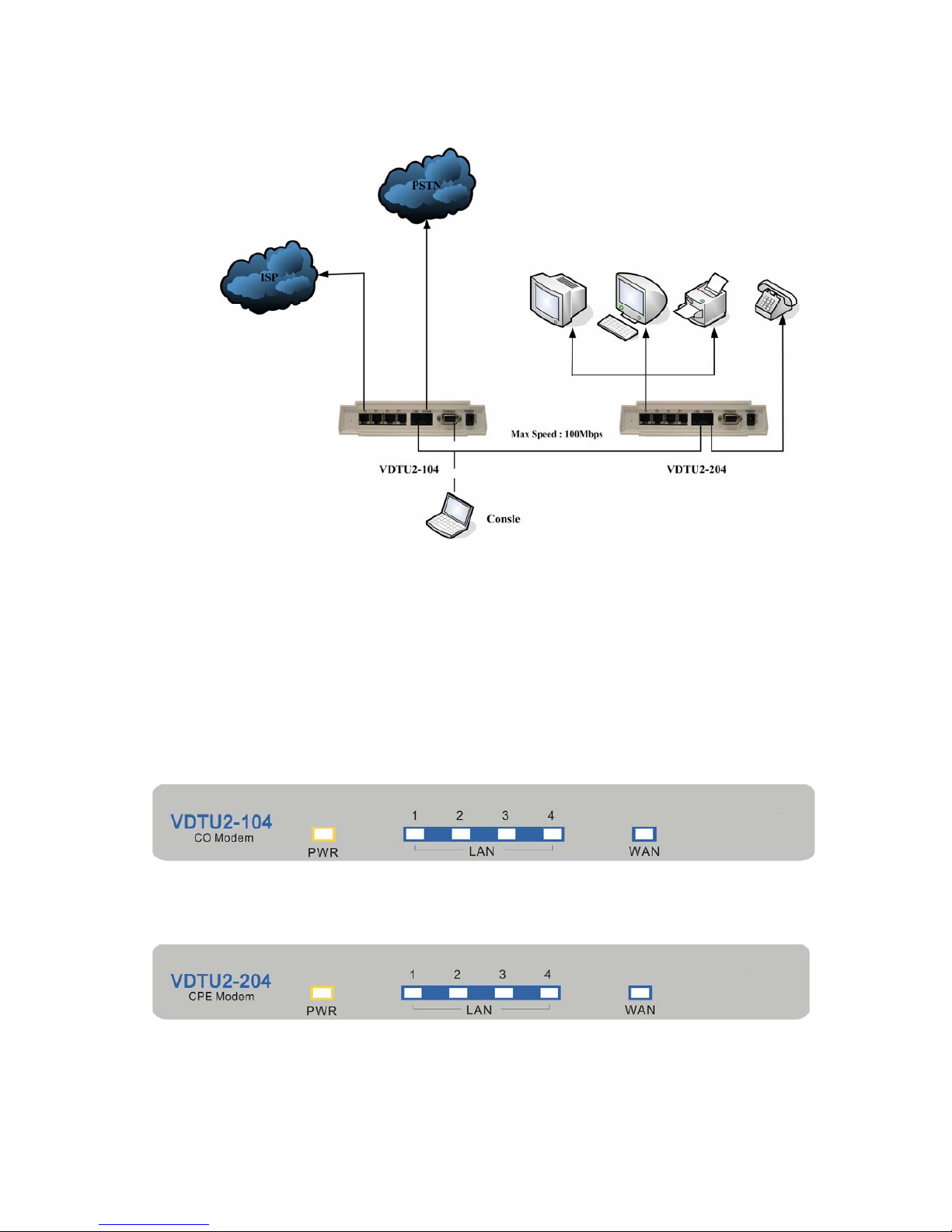
‧Figure 2.1 VDSL2 Point to Point application
3. Hardware Description
This section describes the important parts of the VDTU2-104 & 204 MODEM. It features
the front indicators and rear connectors.
Front Indicators
The following figure shows the front panel.
Figure Chapter 3.1 VDTU2-104 Modem
Figure Chapter 3.2 VDTU2-204 Modem
Six LED indicators.
At a quick glance of the front panel, it will be easy to tell if the Modem has
power, signal from its Ethernet RJ-45 port or there is phone line signal
RJ-11port
VDSL2 Manual
6
Front Indicators
LED Description and Operation
The Modem has three LED indicators.
LEDs Status Descriptions
PWR
(Ready LED)
Steady
Green
It will light up (ON) to show that the product is
power good, and system reset OK.
1~4
(Ethernet LED)
Steady Green
Flashing (LINK/ACT)
Each RJ-45 station port on the Ethernet is assigne d an LED li ght
for monitoring port “Good Linkage”. LED is normally OFF after
the power on operation, but will light up steadily to show good
linkage and flashing to show data transmission.
WAN
(VDSL LED)
Steady Green
RJ1 1 station port on the VDSL is as signed an LED light for
monitoring port “Good Linkage”. LED is normally OFF after the
power on operation, but will light up steadily to show good
linkage.
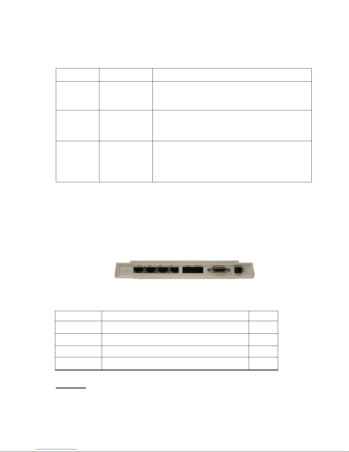
Rear Panel
The following figure shows the rear connectors
Figure Chapter 3.3 Rear Connectors
VDTU2-104&CPE MODEM Rear Connectors
Connectors Description Type
Line
For connecting to the VDSL Modem Using
a RJ-11 cable
RJ-11
Phone
For connecting to the telephone or Fax、ISDN Modem
RJ-11
E1~E4 For connecting to a Ethernet equipped device RJ-45
Console port
For connecting to PC with RS-232 serial
port over a D-SUB Cable
RS-232
Power On
1. Check the adapter is properly connected.
2. Verify the power LED is steadily on.
VDSL2 Manual
7
4. Setup the VDTU2-104&CPE MODEM by Web Browser
The VDTU2-104 & 204 MODEM provides a built-in web browser. You can use Web
browser to configure the VDTU2-104 & 204 Modem. First please input the IP address
192.168.16.249 (VDTU2-104 Modem) and 192.168.16.250 (VDTU2-204 Modem) in
the Web page.
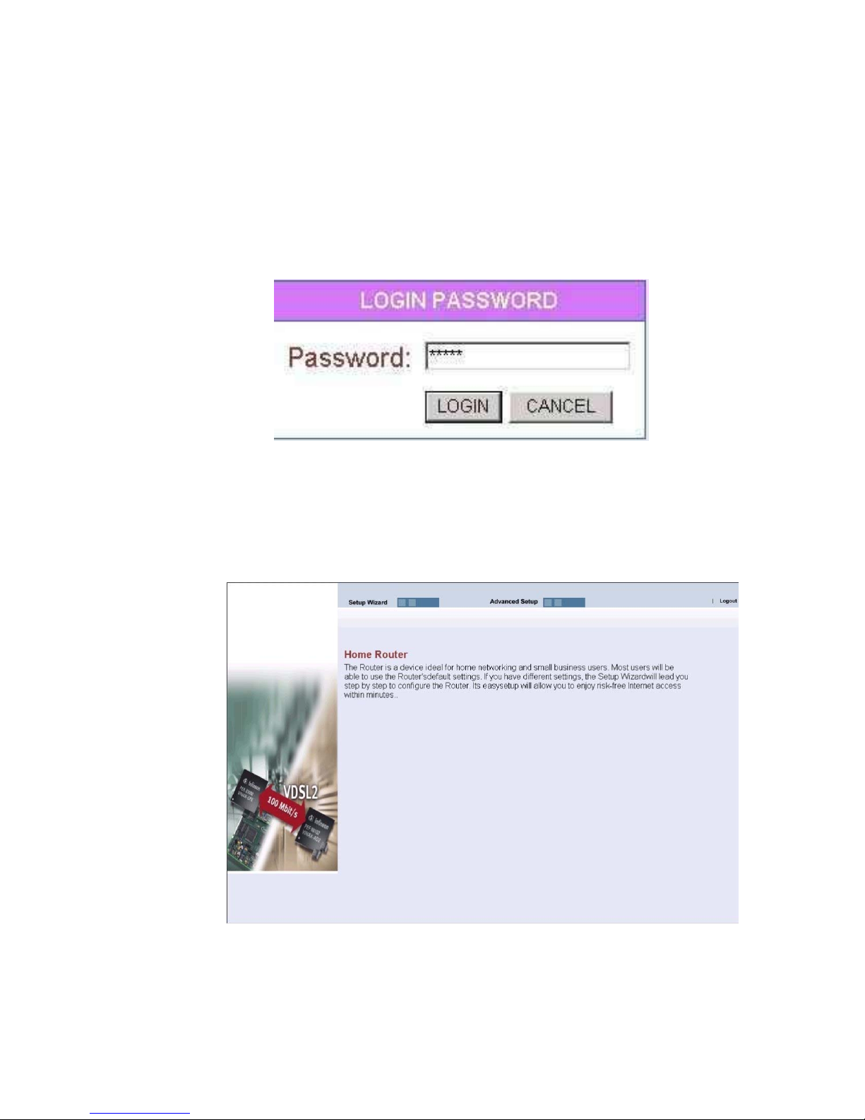
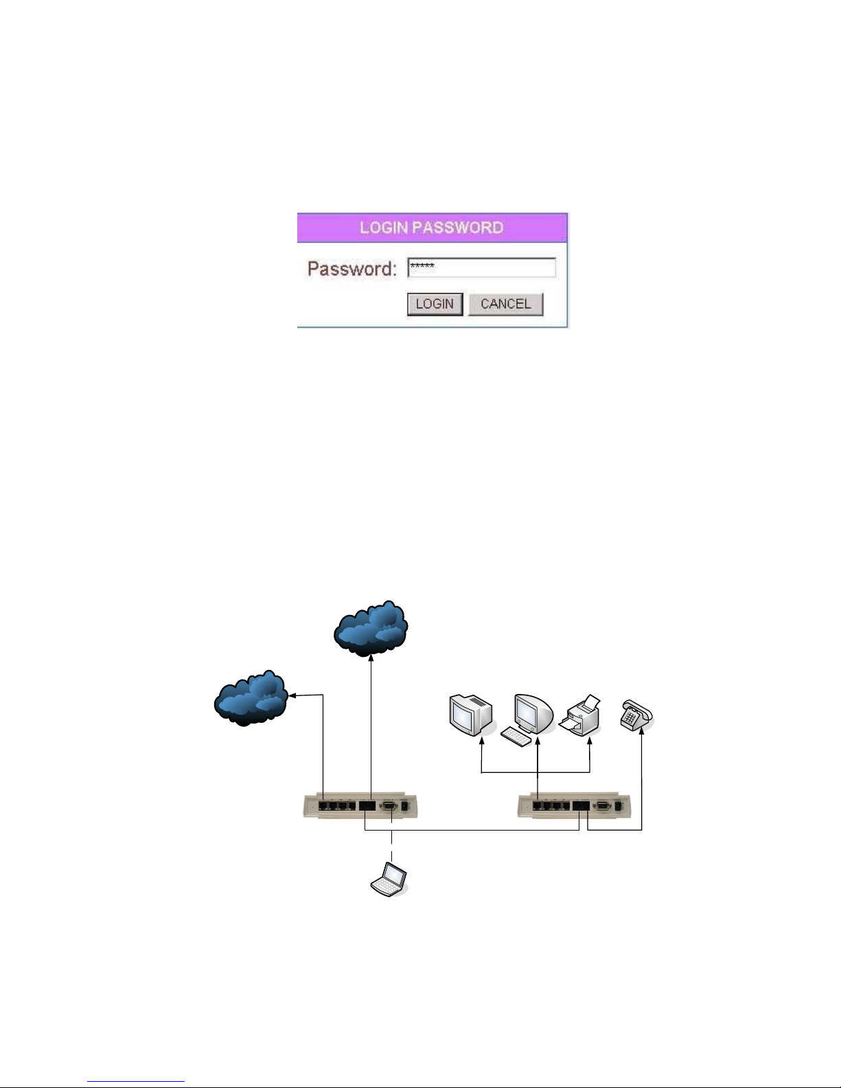
4.1 Login.
The password is “admin“.
Figure 4.1 Login
4.2 Select the Menu Level
There is a simple Setup Wizard for end users and an Advanced Setup. The focus of
this manual is on the Advanced Setup.
Figure 4.2 Select the Advanced Setup in the Entry Screen
VDSL2 Manual
8
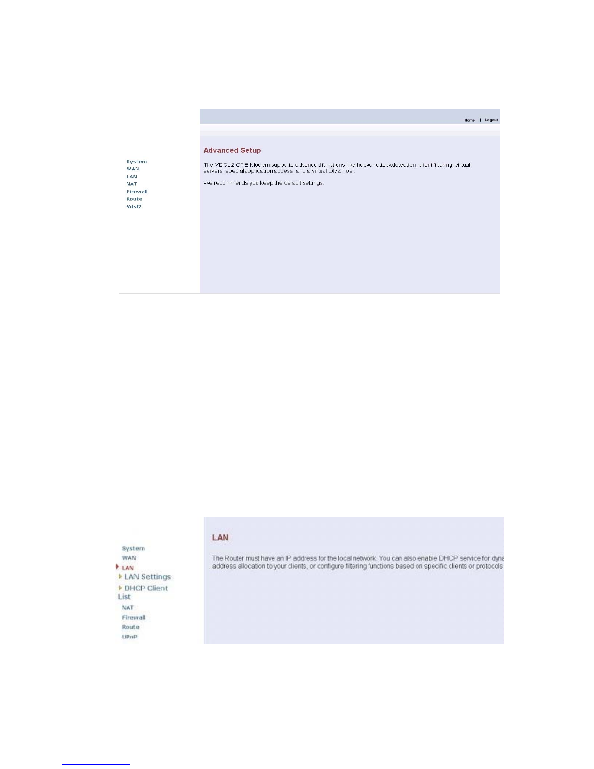
4.3 Select Advanced Setup
Select the Advanced Setup. The menu below will be used frequently. As an exercise
and an example now the IP address will be set.
Figure 4.3 Advanced Setup
Attention: The settings in the following Chapter 4.4 only need to be performed in
order to change LAN settings. Such a change may be necessary when
connecting the VDTU2-104 & 204 Modem for the to a new control PC
and/or in order to turn the IP address changed via a shell command into a
default address for the next restart of the board.
4.4 Select LAN
The menus below will not be used very often. But when connecting the VDTU2-104
& 204 Modem to a new control PC, you may want to go through the following steps
in order to make the IP address previously set by ifconfig in the terminal console
permanent. Or on some later occasion you may want to change it again without
using the console. Then the menu below will help you too.
In order to set the IP address, click on “LAN Settings”.
Figure 4.4 LAN menu
VDSL2 Manual
9
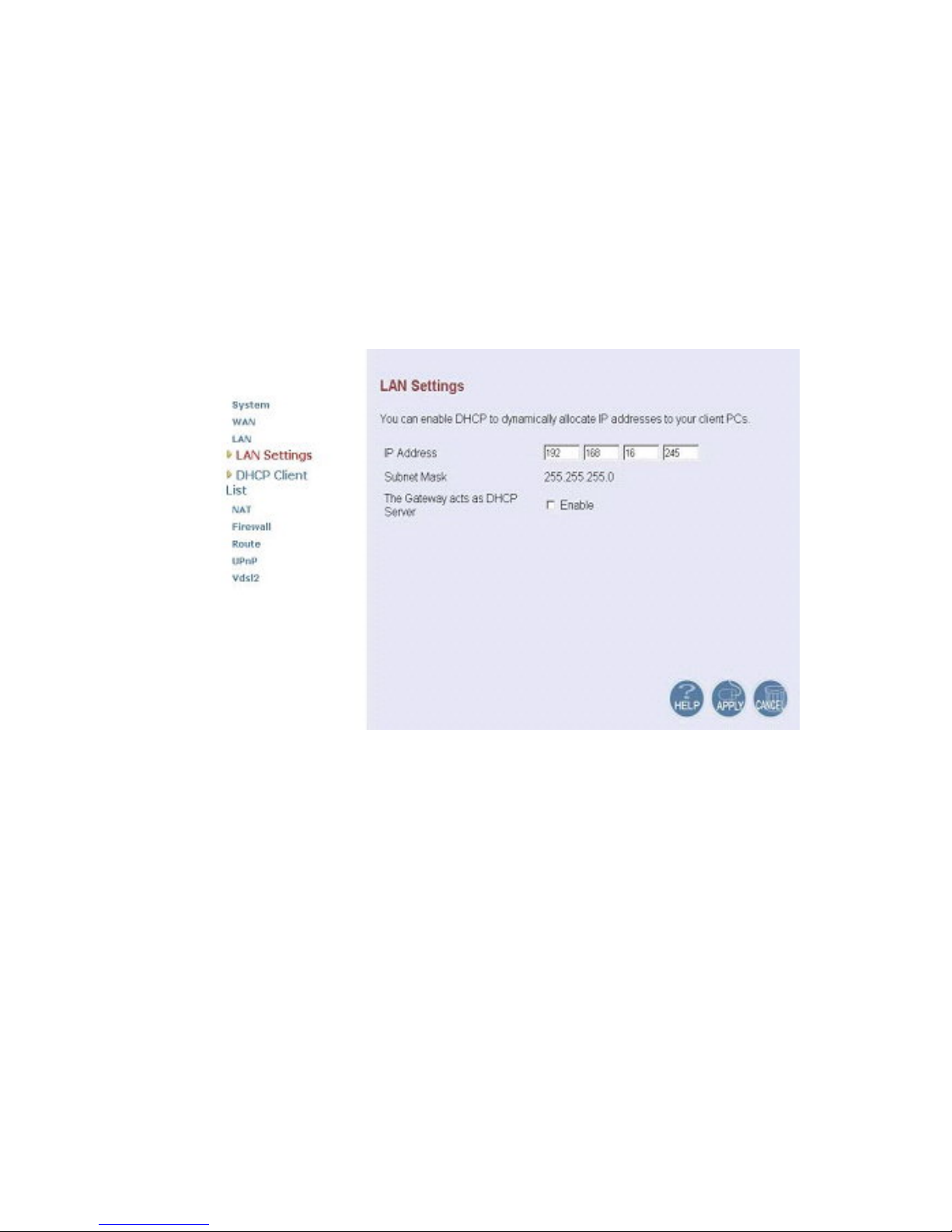
4.4.1 Select LAN Settings and set the IP Address
The form below is used to change the IP address of the LAN port “adm0” in the
VDTU2-104 & 204 Modem.
‧ The proposed IP address either is the default address of adm0 or it is the
address changed by an ifconfig command via the shell running in the terminal.
‧ The Subnet Mask display can be ignored.
‧ In case the DHCP checkbox is checked, some additional data and options will
be on display (see Chapter 6.2.5.1 on Page 50). The DHCP server is not
required to work with VDSL2 in a lab environment. It is recommended to
uncheck the box if it is not unchecked already.
Figure 4.4.1 LAN Settings
Now the IP address either may be changed or left as it is. If it has been
changed in the form or after it has been changed using the ifconfig command
via the shell running in the terminal, it needs to be stored permanently Hit the
“APPLY” button in order to make the displayed IP address new default
address.
VDSL2 Manual
10
4.4.2 Restart the Settings Dialog
After the “APPLY” button has been hit, the displayed IP address “adm0” port
will be stored in a non volatile memory on the VDTU2-104 & 204 Modem. Also,
the Ethernet link between the control PC and the VDTU2-104 & 204 Modem
will be re-initialized – even if the IP address has not been changed. Refresh
the display of the HTTP browser running on the control PC and login again.
Figure 4.4.2 Login after Storing the IP Address as Default Value
The VDTU2-104 & 204 Modem now is prepared to be controlled by the
control PC.
5. Building a VDSL2 System
First a quick overview over a complete setup:
Figure 5 VDSL2 Application
VDSL2 Manual
11
5.1 Connect the VDTU2-104 Modem and the VDTU2-204 Modem to the Line
The objective for VDSL2 is passing data over a twisted pair cable at high speed. In
the setup, either such a cable connects the VDTU2-104 Modem and the
VDTU2-204 Modem, or a line simulator or any other hardware representation of a
cable network, with or without noise injection and crosstalk simulations.
5.2 Connect the VDTU2-104 Modem and the VDTU2-204 Modem to LAN Devices
In the setup, usually a Ethernet tester serves as representation of the LAN side as
well as representation of the WAN side.
5.3 Run Demos and Tests
The Ethernet tester may send data downstream as well as upstream. It also
receives the data in order to check the integrity of the data transmission.
Different data rates can be tested under different line conditions.
6. Operating the VDSL2 System
After the VDSL2 system has been set up, you may want to configure the settings which
is related to VDSL2. Configuration of operation modes, test modes (loop back) and
the display of status information is supported by an graphical user interface.
6.1 Configuration Settings
Configure and start the VDTU2-104 Modem and the VDTU2-204 Modem.
‧ Configuration: As a minimum configuration, usually selecting the bandplan is
required.
See Chapter 6.1.3, Profile Configuration.
‧Next, both sides should be activated from the web interface.
See Chapter 6.1.6, Line Activation
‧The connection status of the link can be monitored.
See Chapter 6.2.1, Line Status
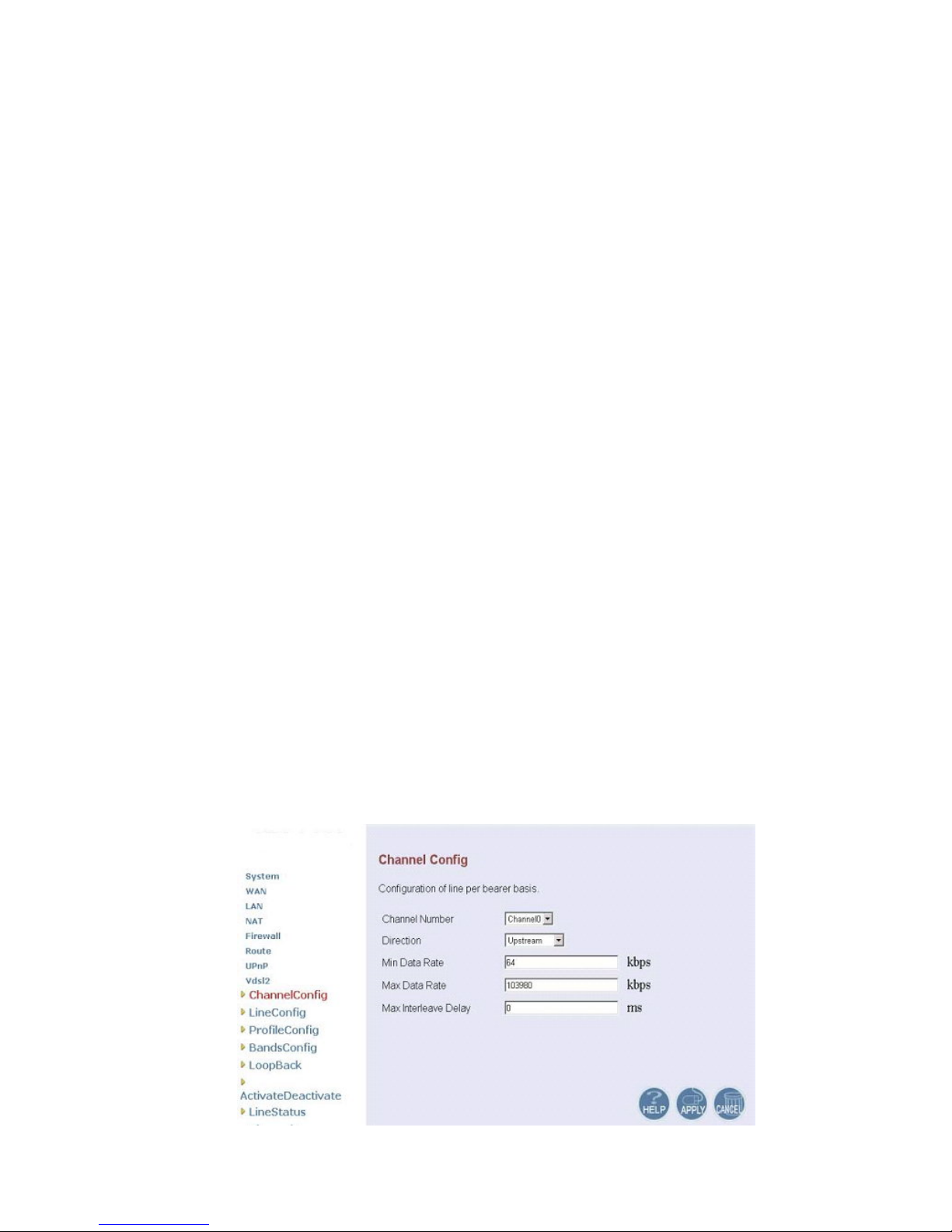
6.1.1 Channel Configuration
VDSL2 Manual
12
Figure 6.1.1 Channel Configuration Menu
Channel Configuration Settings
Setting Description
Channel Number To which bearer channel number shall the settings apply?
‧Channel 0
Direction To which direction shall the settings apply?
‧Upstream
‧Downstream
Min Data Rate Minimum Payload Data Rate
Max Data Rate Maximum Payload Data Rate
Max Int Delay Maximum Interleaver Delay
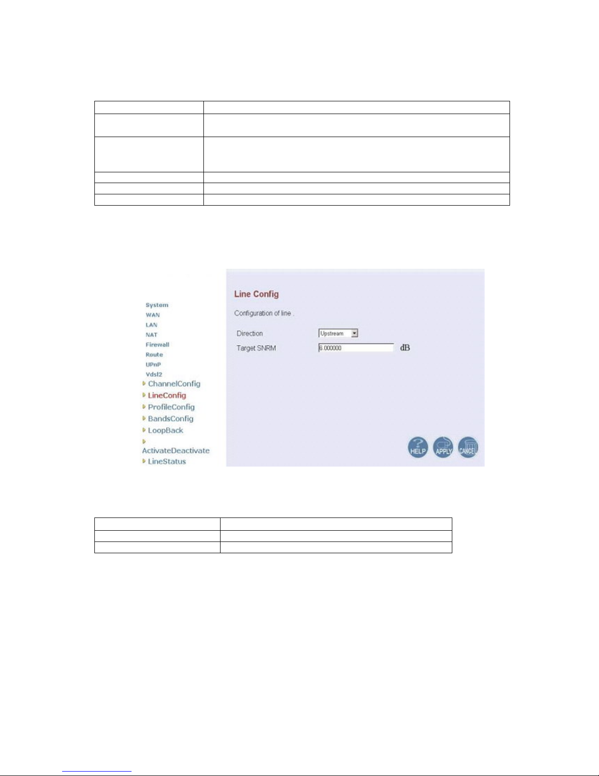
6.1.2 Line Configuration
Figure 6.1.2 Line Configuration Menu for SNR Margin Selection
Line Configuration
Setting Description
Direction Select the target direction.
Target SNRM Set the required SNR Margin *10 (50=5dB)
 Loading...