

TeleWell TW-EA701-715 User Manual

1
TeleWell TW-EA701-715
Multi-Mode
ADSL Router
User’s Manual
January 2002

2
Copyright
All rights reserved. No part of this document may be reproduced in any form or by any means
without written permission from Easytel Oy.
Changes are periodically made to the information in this document. They will be incorporated in
subsequent editions. The product manufacturer may make improvements and/or changes in the
product described in this document at any time.

3
Table of Contents
Chapter 1 Introduction
5
1.1 Overview 5
1.2 Features and Compatibility 6
1.3 What’s in the package?
6
1.4 Important Rules for Safe Operation 7
1.5 Front Panel
8
1.6 Real Panel 9
Chapter 2 Installing and Configuring your ADSL
Router
10
2.1 Preparation for Hardware and Software Installation 10
2.2 Hardware Installation 11
2.3 Windows 95/98 setting for Ethernet LAN connection
12
2.3.1 Check TCP/IP protocol 12
2.3.2 TCP/IP installation 13
2.3.3 TCP/IP setting
14
2.4 Configuring the Router 16
2.4.1 Using TELNET via Ethernet interface
16
2.4.2 Using terminal program via serial console port 17
Chapter 3 Basic Configurations
19
3.1 Factory default configuration 19
3.2 Bridged RFC1483 20
3.3 Routed RFC1483
21
3.4 Classical IP (RFC1577) 22
3.5 PPP Over ATM (RFC2364)
25
3.6 PPP Over Ethernet (RFC2516) 26
Chapter 4 Advanced Configurations 27
4.1 Add NAT to Classic IP, PPP over ATM and PPP over Ethernet
27
4.2 Enables NAT to RFC1483, Classic IP (RFC1577), PPP over ATM
(RFC2364) and PPP over Ethernet (RFC2516) in Routing mode
28
4.3 Changing DHCP server configuration 29
4.4 Changing DHCP client configuration
31
4.5 PPTP Tunneling Configuration 32
Chapter 5 Managing The ADSL Router
34
5.1 Booting the ADSL Router from Ethernet Network 34
5.2 Upgrading on-board flash memo from Ethernet network 34
5.3 SNMP
34

4
Chapter 6 ADSL Link Performance Statistics
35
Chapter 7 Command Sets for Command Line
Interface
35
Command Line Interface Conventions 35
Basic system command sets 36
Commands for ISFS and FLASHFS process
38
Commands for Bridge process
39
Commands for DHCP server process
44
Commands for DHCP client process 45
Commands for IP process
47
Commands for NAT process 58
Commands for PPP process
161
Commands for SNMP process 167
Commands for ADSL process
168
Chapter 8 DHCP Server Operation
70
8.1 DHCP Server Overview 70
8.2 DHCP Server Configuration 70
8.3 Informal configuration guide
70
8.4 Configuration reference guide 71
Chapter 9 DHCP Client Configuration
80
9.1 Protocol Timing 80
9.2 Lease requirements and requests 81
9.3 Other declarations
82
9.4 DHCP Options 82
Appendix A Product Specifications
84
Appendix B Troubleshooting
85
Appendix C Glossary
87
Appendix D Government Compliance Notices
91

5
Chapter 1 Introduction
1.1 Overview
This ADSL Router features multi-mode ADSL technology that provides a downstream rate of up to 8M
bps over existing copper wire lines, which is more than 100 times faster than a traditional 56K analog
modem. And it can be connected to your PC or LAN through the 10Base-T or 100Base-T Ethernet
interface.
This ADSL Router is designed to meet both the needs of single user, and multiple users at small office
and home office who want fast Internet access. A wide variety of features and interoperability offer
scalability and flexibility for all the applications

6
1.2 Features and Compatibility
This Heritage series Router provides the following features:
z Multi-mode ADSL technology supports ITU-T G.hs, G.dmt, G.lite and ANSI T1.413 issue 2 to
provide interoperability with most of DSLAM equipments.
z ATM (Asynchronous Transfer Mode) protocol allows the QoS(Quality of Service)
transmission over a network
z Support for text-based and Windows-GUI based console management over Telnet and serial
connection
z Support for remote configuration by your network administrator via IP network.
z Support IEEE 802.1d transparent bridging with spanning tree algorithm.
z Bridge filtering allows a network administrator to control the flow of packets across the router
z NAT : let multiple users on the LAN share one Internet connection simultaneously
z SNMP agent: allows monitoring and configuration by a standard SNMP manager.
z BOOTP/TFTP enable the remote configuration
z Point-to-Point Protocol (PPP)
z RFC 1483 Link Protocol
z Password Authentication Protocol (PAP) and Challenge Handshake Authentication Protocol
(CHAP) security under PPP protocol
z IP routing support includes the RIP(Routing Information Protocol) which allows the exchange
of routing information on a TCP/IP network
z Flash memory for Software upgrade
z Status LEDs for easy monitoring and troubleshooting
Some models of ADSL Router provides more features:
z DHCP client : let an ISP dynamically issue an address upon initial connection.
z DHCP server : automatically assigns IP addresses to all computer on the LAN.
z DNS relay : allows for automatic name resolution when no DNS information is configured by
the user.
z PPTP tunneling enable VPN configuration.
z Including 4 ports 10/100 Base-T Ethernet Stackable Switch Hub.
1.3 What’s in the package?
z One ADSL Router
z One 9VDC or 12VDC Adaptor, depend on different model
z One RJ-11 Telephone Cable
z One 10Base-T Ethernet straight-through Cable
z One 9-pin to 9-pin RS-232 Cable (optional)
z One User’s Guide
All packages have been checked carefully for their completeness and functionality before shipped.
Please contact the place of purchase if any of the above listed items are missing or damaged.
If you encountered any difficulty in using this product while all the above items are complete, please
refer to Appendix C for Troubleshooting information before making the decision to return your ADSL
Router to your dealer.

7
1.4 Important Rules for Safe Operation
In addition to the careful attention devoted to quality standards on the manufacture of your ADSL
Router, safety is a major factor in the design of every product. However, safety is your responsibility, too.
This section lists important information that will help assure your enjoyment and proper use of the
ADSL Router and accessory equipment. Please read them carefully before operation and using your
Router.
z Read and Follow Instructions – you should read all the safety and operating instructions before
operating the Router.
z Retain Instructions – You should save all the safety and operating instructions, for your future
reference.
z Heed Warning – Comply with all warnings on the products and in the operating instructions.
z Check Power Sources – Operate this product only from the type of power source indicated on
the product’s marking label. If you are not sure of the type of power supplied to your home,
consult your dealer or local power company.
z Be Careful of Overloading – Do not overload wall outlets or extension cords, as this can result
in a risk of fire or electric shock. Overloaded AC outlets, extension cords, frayed power cords,
damaged or cracked wire insulation, and broken plugs are dangerous. They may result in a
shock or fire hazard. Periodically examine the cord, and if its appearance indicates damage or
deteriorated insulation, have it replaced by your service technician.
z Protect Power Cords – Route power supply cords so that they are not likely to be walked on or
pinched by items placed upon or against them. Pay particular attention to cords where they
are attached to plugs and convenience receptacles, and examine the point where they exit
from the product.
z Check Ventilation – Slots and openings in the enclosure are provided for ventilation to ensure
reliable operation of the product and to protect it from overheating. Do not block or cover
these openings. Never block these openings by placing the product on a bed, sofa, rug, or
other similar surface. Never place this product near or over a radiator or heat register, or any
other heat source (including amplifiers). Do not place this product in a built-in installation,
such as a bookcase or equipment rack, unless you provide proper ventilation.
z Do Not Use Accessories – Do not use attachments, unless they are recommended by your
vendor, as they may cause electrical or fire hazards.
z Use the Recommended Power Adaptor – You must use the Power Adaptor that comes with
your ADSL Router.
z Do Not Use Near Water – Do not use this product near water. For example, near a swimming
pool, bath tub, wash bowl, and the like.
z Do Not place Near High Temperature Source – For example near a steamer, kitchen range fire,
and the like.
z Use Caution in Mounting This Product – Do not place this product on an unstable surface or
support. The product may fall, causing serious injury to a child or adult, as well as serious
damage to the product.
z Use Care in Moving Product-and-Cart Combinations – Quick stops, excessive, force and
uneven surfaces may cause the product-and-cart combination to overturn.
z Unplug Power Before Cleaning – Do not use liquid cleaner or aerosol cleaner. Use a damp cloth
for cleaning.
z Keep Objects Out of Openings – Never push objects of any kind into this product through
openings, as they may touch dangerous voltage or “short-out” parts, which could result in a
fire or electric shock. Never spill liquid on the product.
z Protect From Lightning – For added protection for this product during a lightning storm, or
when it is left unattended and unused for long periods of time, unplug it from the wall outlet,
and disconnect the cable system. This will prevent damage to the product due to lightning and
power line surges.
z Turn Off the Power Switch Between DC Plug Off and On.
z Do Not Remove Covers – Do not attempt to service this product yourself, as opening or
removing covers may expose you to dangerous voltage or other hazards.
z Unplug this Product From Wall Outlet Carefully, as the Power Adaptor May Be Hot.

8
z Refer Servicing to Qualified Service Personnel Under the Conditions Listed Below.
When the power supply cord or plug is damaged.
If liquid has been spilled or objects have fallen into the product.
If the product has been exposed to rain or water.
If the product does not operate normally by following the operating instructions. Adjust
only those controls that are covered by the operating instructions.
If the product has been dropped or the cabinet has been damaged.
When the product exhibits a distinct change in performance, such as the inability to
perform basic functions – this indicates a need for service.
z Require Safety Check – Upon completion of any service or repairs to this product, ask the
service technician to perform safety checks recommended by service point to determine that
the products is in safe operating condition.
1.5 Front Panel
The ADSL Router has five status LEDs for diagnostics. You can monitor the LEDs during operation.
Following table shows the ADSL Router status LEDs and identifies what each LED light means.
Function Behavior Definition
Dark Power off POWER
Light Power on
Flashing slowly ADSL training in progress ADSL
Light ADSL link is establish and ready to
transfer data
Dark Ethernet link absent or power off PC
Light Ethernet link present
RX Flashing Receiving data from ADSL link
TX Flashing Transmitting data to ADSL link
The ADSL Router which including 4 ports stackable switch hub that has several status LEDs for
diagnostics. You can monitor the LEDs during operation. Following table shows the ADSL Router status
LEDs and identifies what each LED light means.
Function Behavior Definition
Dark Power off POWER
Light Power on
TX/RX Flashing Transmitting/Receiving data to/from
ADSL link
Flashing slowly ADSL training in progress LINK
Light ADSL link is establish and ready to
transfer data
Dark Ethernet link absent or power off L1 ~ L4
Light Ethernet link present

9
1.6 Rear Panel
The rear panel of the ADSL Router consist of power jack, Console Port connector, Ethernet connect and
ADSL link jack which they means as below:
Function Definition
ADSL ADSL jack connect to DSL line from TelCo.
10Base-T or
100Base-T
Ethernet interface connect to PC or HUB for
LAN.
Console This is RS232C interface and use to
management ADSL Router.
DC 9V or
DC12V
The power jack connects to Adaptor from wall
outlet.
This is only for TW-EA715 model
The rear panel of the ADSL Router which including 4 ports stackable switch hub consist of power jack,
Console Port connector, Ethernet connects and ADSL link jack which they means as below:
Function Definition
ADSL ADSL jack connect to DSL line from TelCo.
Up-Link This is HUB feature cascade to another HUB for
expand LAN.
L1 ~ L4 Ethernet Ports: Port1 to Port4
Console This is RS232C interface and use to
management ADSL Router.
DC 9V or
DC12V
The power jack connects to Adaptor from wall
outlet.
10
Chapter 2
Installing and Configuring your ADSL Router
The major functions of the ADSL Router are performed by using Ethernet 10Base-T or 10/100Base-T
network interface. Your computer has to install an Ethernet NIC card and set up the TCP/IP protocol
before start to using the ADSL Router.
The ADSL Router also provides a serial console port for monitoring and configuring the Router via the
ADSL Configuration Tool.
2.1 Preparation for Hardware and software installation
Before start the hardware installation. Please prepare all the materials listed below regarding to your
application.
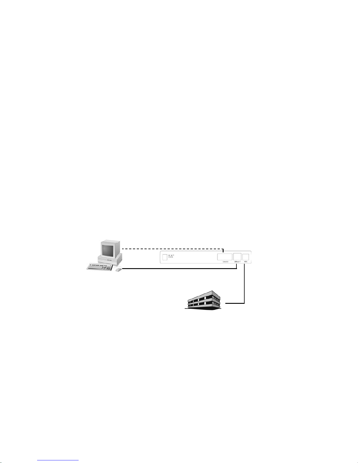
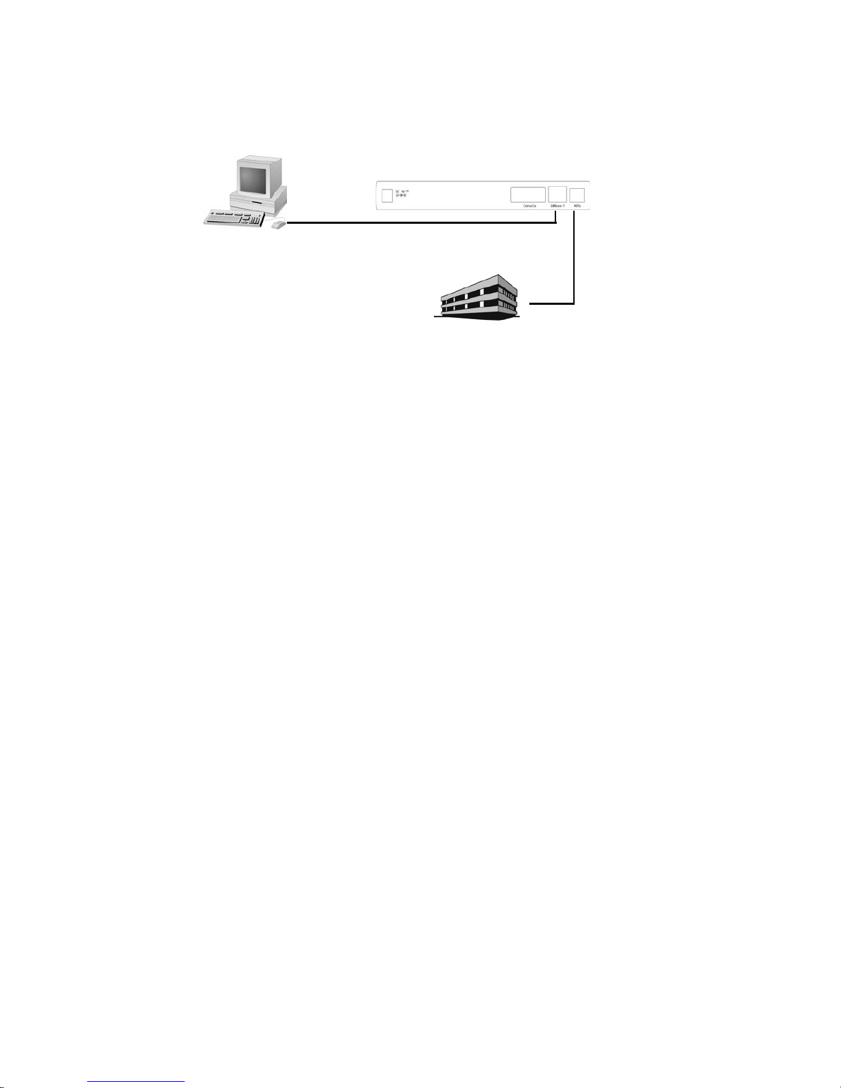
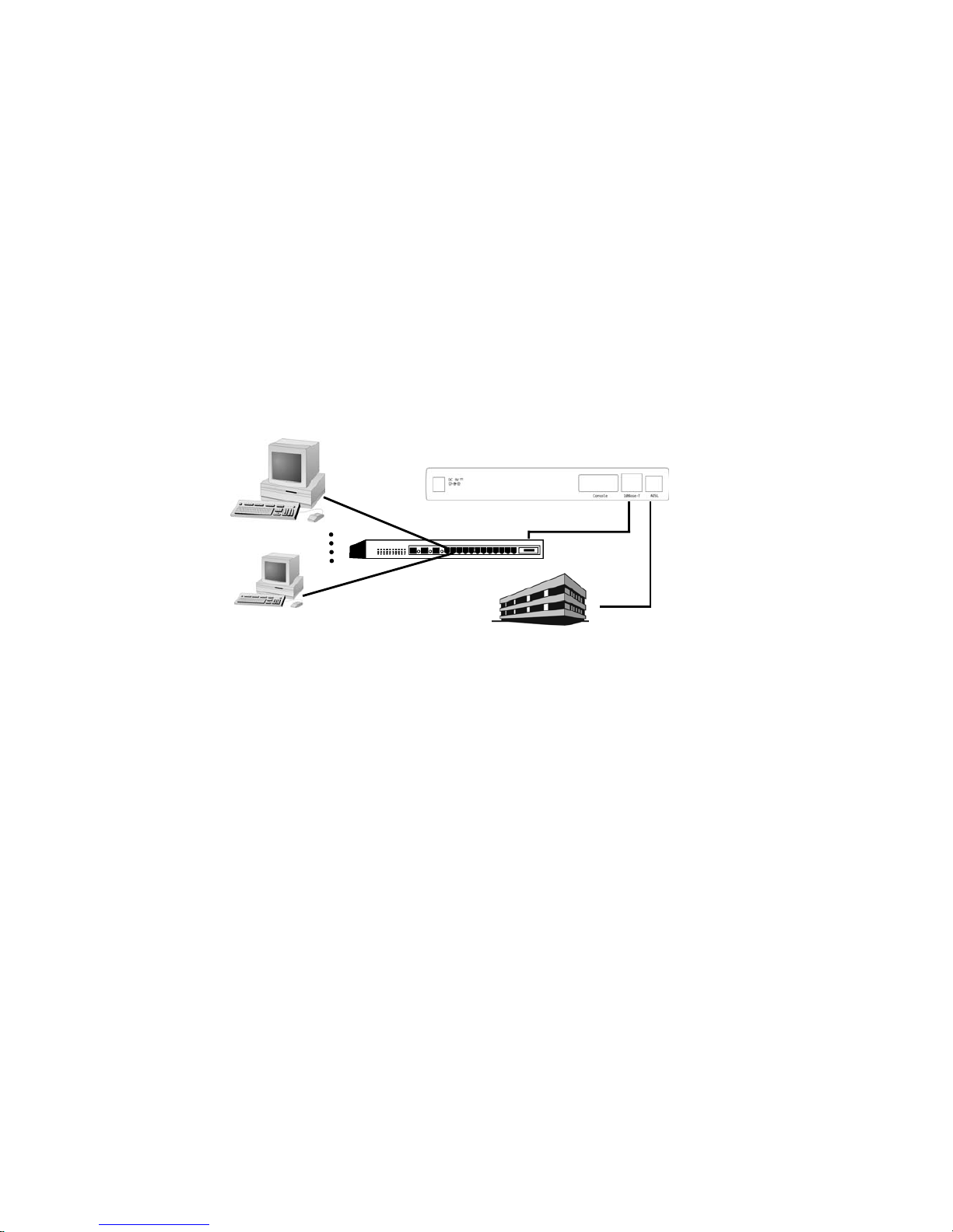
1. Connect to a computer directly
ADSL service provider or ISP/NSP service contract. Please sign an appropriate
Internet connection contract with a reliable ISP/NSP and get necessary connection
information that will help you configuring your Router.
Personal computer with OS that support Ethernet interface
TCP/IP protocol installed in your personal computer
10Base-T Ethernet card
10Base-T Ethernet straight-through cable (included in this package)
RJ-11 telephone cable (included in this package)
RS-232 serial cable (optional)
Power adaptor (include in this package)
DSLAM/ISP
Ethernet Port
Serial Port
10Base-T Port
Consol Port
11
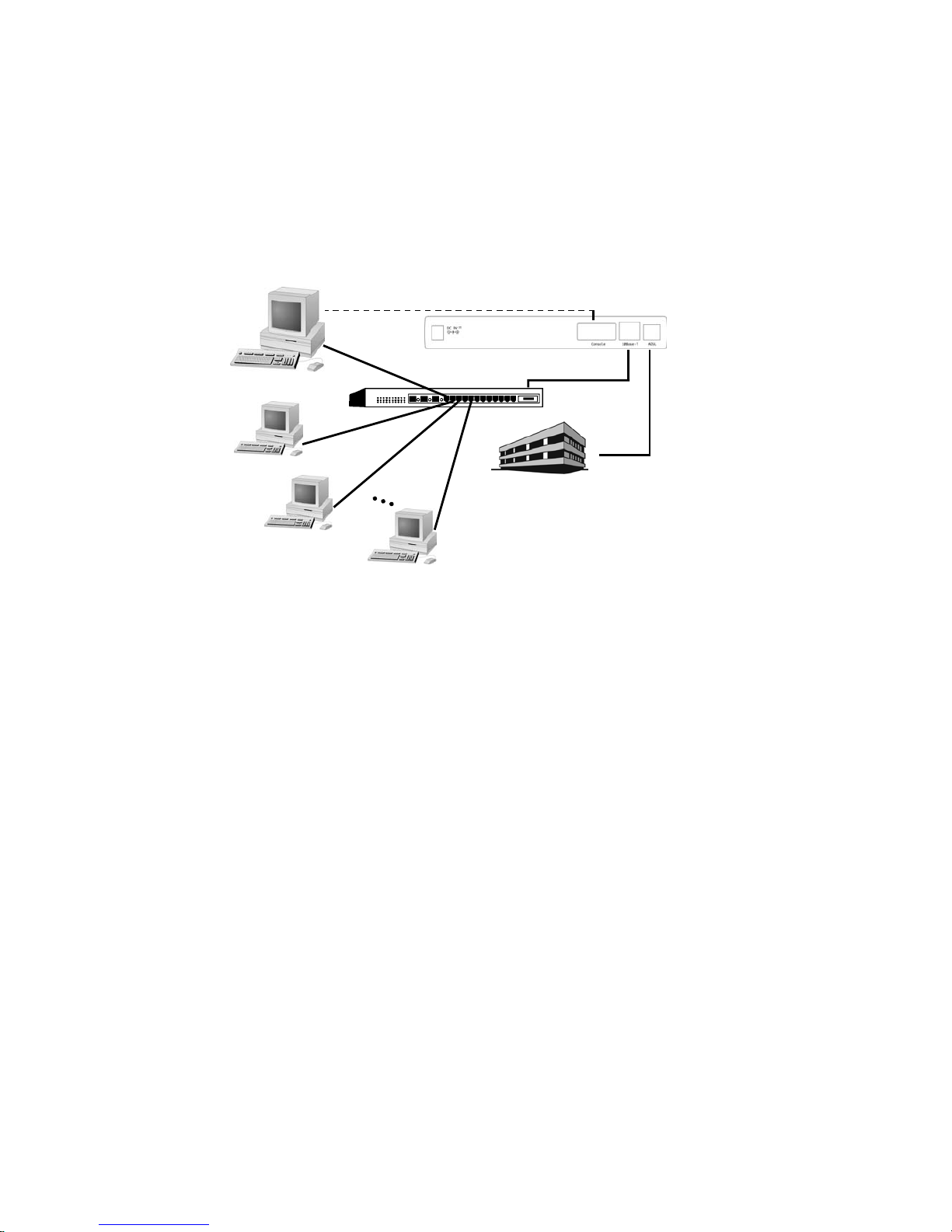
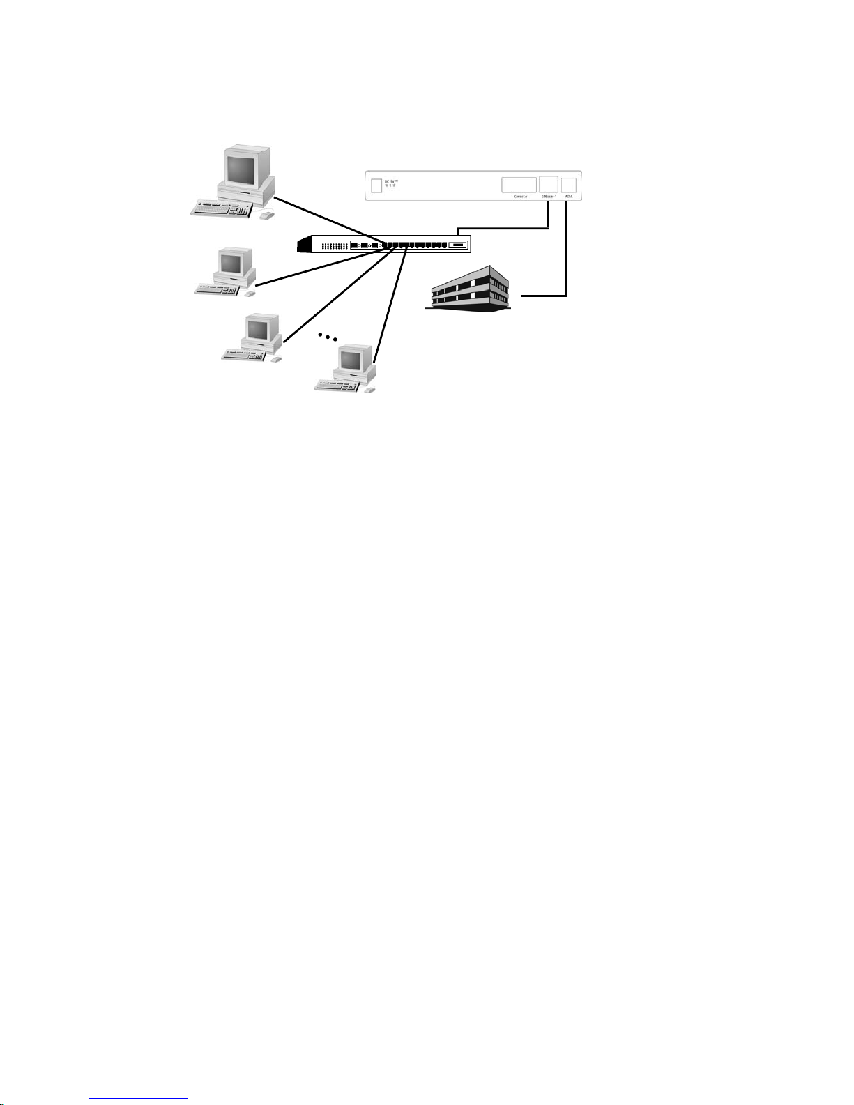
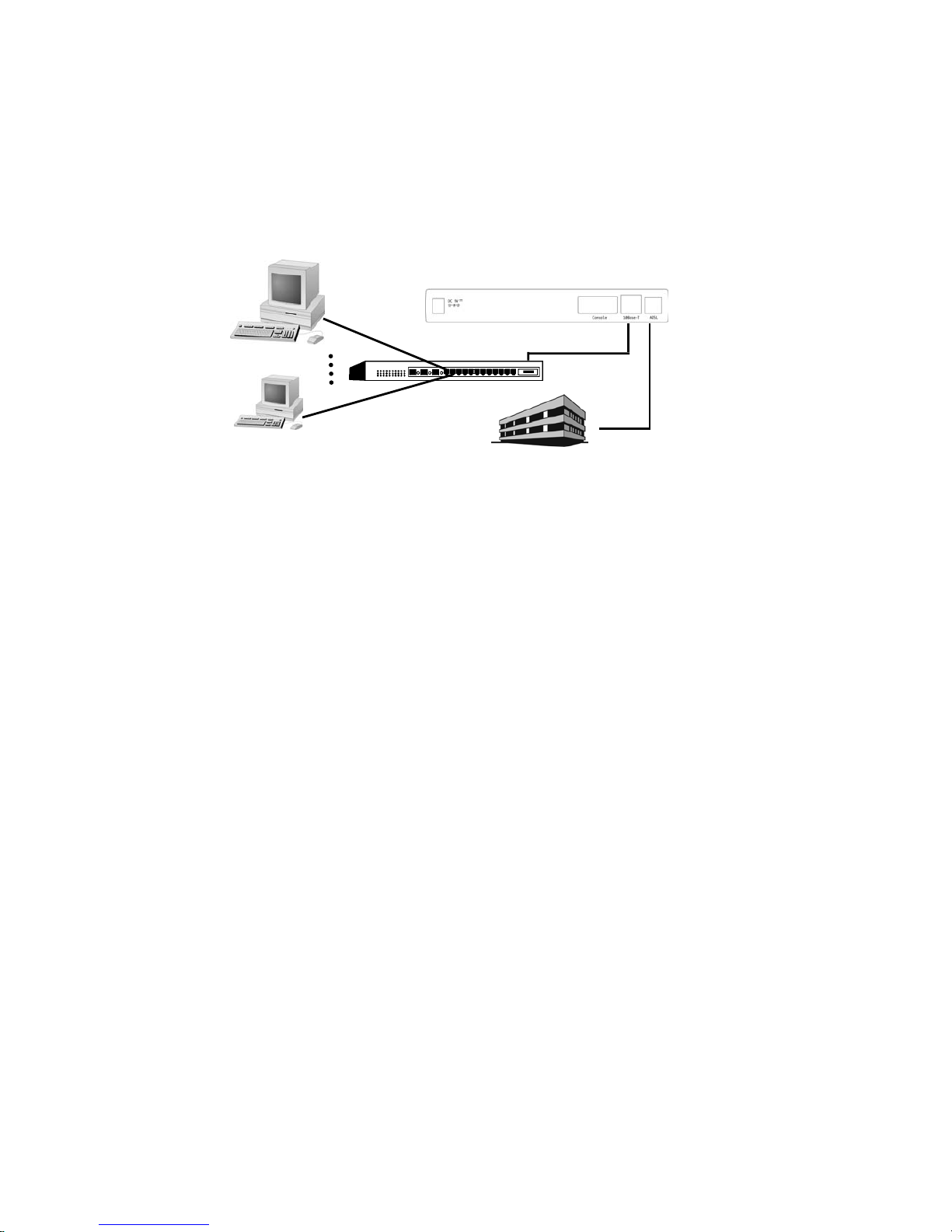
2. Connect to more than one computer
Excepts the items listed on step 1 above, you still need following items:
Additional PC with OS that support Ethernet interface.
Additional 10Base-T Ethernet card for each PC you want to connect
Additional 10Base-T Ethernet Straight-through cable for each PC you want
to connect.
One Ethernet Hub is required for more than one computer connection.
If your up-link hub without cascade switch, please prepare a 10Base-T
Ethernet crossover cable instead of the straight-through cable that listed on
step 1 above.
2.2 Hardware Installation
Before start to configure your Router, you have to complete all the hardware installation. The following
steps provide instructions for installing your Router.
1. Be sure the power switch on the right side of the Router is at the OFF status.
2. Connect the power adaptor to the power jack that marked Power at the rear panel of the
Router, then plug in the DC power adaptor to the wall electrical outlet.
3. Connect the 10Base-T cable.
A) If connect to computer directly
Connect one end of 10Base-T Ethernet straight-through cable to the Ethernet port on
your computer, then connect the other end of 10Base-T Ethernet straight-though cable to
the connector that marked 10Base-T at the rear panel of the Router.
B) If connect to more than one computer via Hub
Connect one end of 10Base-T Ethernet straight-through cable (If your up-link hub
without cascade switch, please use a 10Base-T Ethernet crossover cable instead) to the
uplink port on the Ethernet Hub, then connect the other end of 10Base-T Ethernet cable
to the connector that marked 10Base-T at the rear panel of the Router.
4. Connect one end of RJ11 telephone cable to the ADSL line jack that marked ADSL at the rear
panel of the Router, then connect the other end of RJ-11 telephone cable to the ADSL service
port that your ADSL service provider or ISP installed.
5. Connect the male (9 pin) end of the RS-232 serial cable to the connector that marked Console
port at the rear panel of the Router, then plug the other end of the RS-232 serial cable to the
RS-232 serial port of your computer.
6. Turn on the power switch. The Router should perform a self-test, and then be ready for use.
DSLAM/ISP
Ethernet Port
Serial Port
10Base-T Port
Consol Port
Up-Link
PC A
PC B
PC C
PC N
HUB
12
2.3 Windows 95/98/Me setting for Ethernet LAN connection
Either connect to Internet or configure the Router via Ethernet, the TCP/IP protocol is really necessary.
And your computer must be on the same subnet with the Router.
When you directly connect the Router to your computer through the Ethernet network, you will first
configure your computer to obtain an IP address automatically from your Router’s DHCP server, or
specify an IP address and Subnet Mask to the same subnet as remote host. The following steps provides
the instructions to setup your computer to obtain an IP address by using Windows 95/98 on a PC
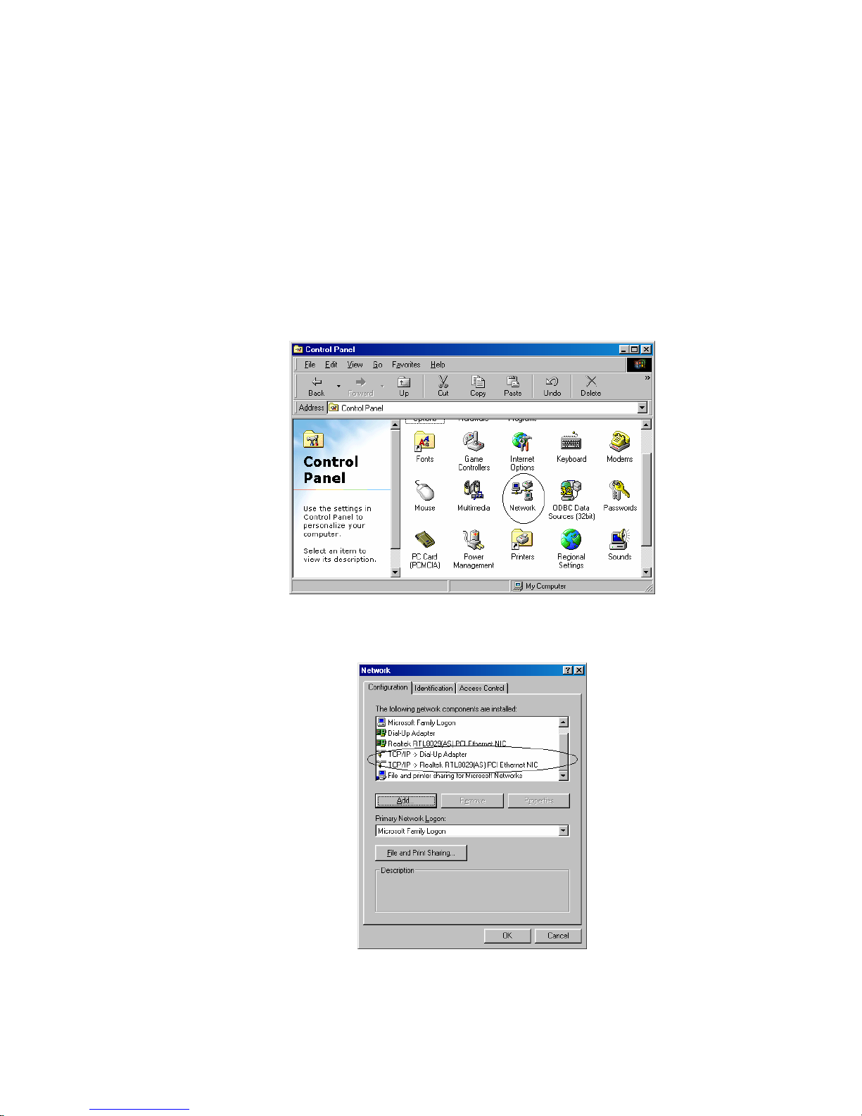
2.3.1 Check TCP/IP protocol
To check if TCP/IP is properly installed, please proceed to the following steps.
1. Double-click on My computer->Control Panel->Network
2. In Network window, check if TCP/IP is shown and properly setup for the Ethernet card that
installed in your computer (for example, TCP/IP->Realtek RTL8029(AS) PCI Ethernet NIC).
3. When TCP/IP has properly installed, please proceed to 2.3.3 TCP/IP Setting
4. When TCP/IP has not properly installed, go to next section to install the TCP/IP protocol.
13
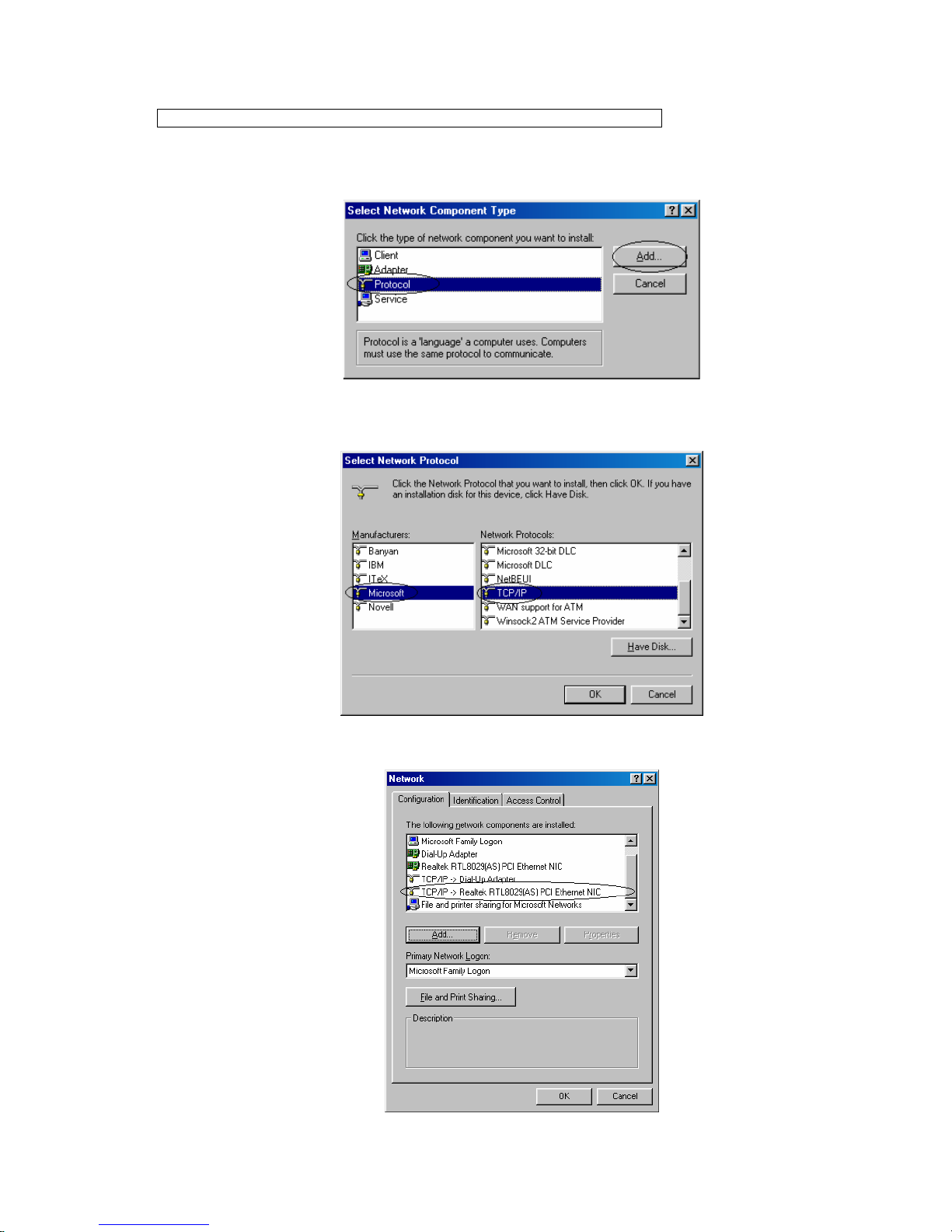
2.3.2 TCP/IP installation
Attention: When install TCP/IP protocol, you need Windows CD-ROM
1. In Network window, click the Add button.
2. Choose the Protocol and click Add.
3. In Select Network Protocol window, choose Microsoft in Manufacturers and TCP/IP in
Network Protocols. Then click OK
4. Confirm if the TCP/IP protocol has been correctly setup with your Ethernet card.
14
2.3.3 TCP/IP setting
Attention: When connecting your ADSL Router with existing LAN, consult
your network manager for correct configurations
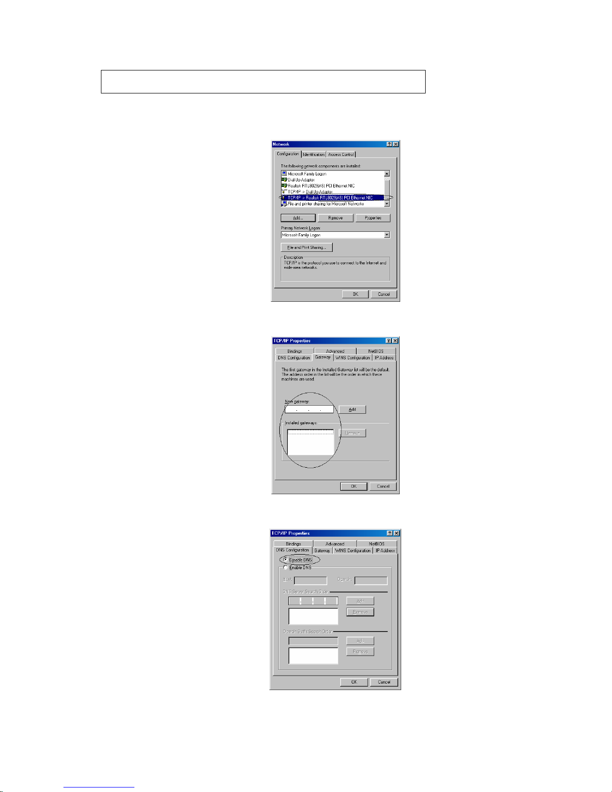
1. In Network window, double-click the TCP/IP service for the Ethernet card that installed in
your computer(for example, TCP/IP > Realtek RTL8029(AS) PCI Ethernet NIC).
2. Click the Gateway tab, and remove any installed gateways.
3. Click the DNS configuration tab, and click the disable DNS button.
15
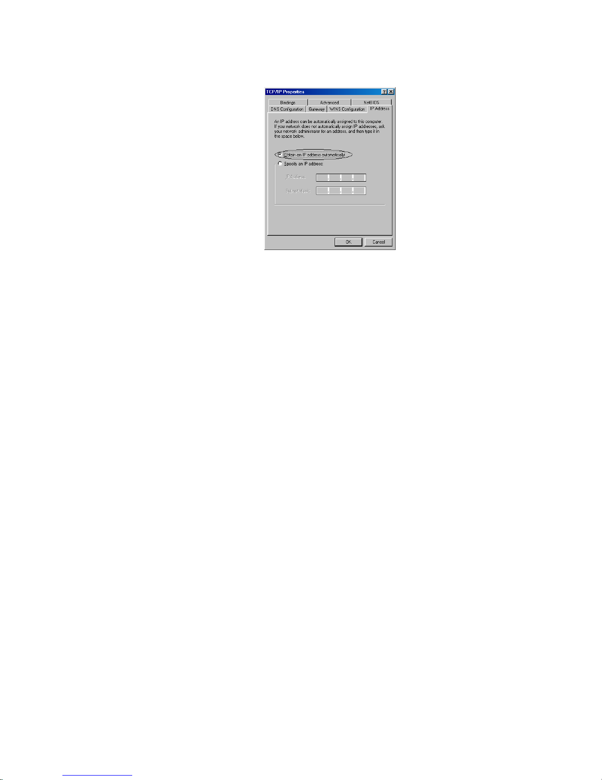
4. For DHCP client, Click the IP address tab, and click the Obtain an IP address automatically
button.
For Fixed IP or DHCP server, Click the IP address tab, and click the Specify an IP address
button. Then set IP Address and Subnet Mask to the same subnet as remote host. Refer to
Chapter 3.2 for example.
5. Click OK to save the new setting.
6. Click Yes when prompted for “Do you want to restart your computer ?”. Your computer will
restart to make the new setting in effects.
7. Now your computer is ready to access your Router via Ethernet network.

16
2.4 Configuring the Router
There is some setup required to get your ADSL Router working properly. The configuration of the ADSL
Router can be accessed in three ways:
z Using TELNET via Ethernet interface
z Using terminal program via serial console port
z Using ADSL Configuration Tool (ACT) via serial console port
2.4.1 Using TELNET via Ethernet interface
To access the command line interface via Ethernet interface, you can use TELNET to log in the
Router from the local Ethernet network using the Ethernet IP address that assigned to your ADSL
Router. The Ethernet IP of the ADSL Router is default set to 192.168.7.1.
1. Select Start->Programs->MS-DOS Prompt.
2. Find the IP address of the Router’s Ethernet port. Then use TELNET to login the Router. For
example, TELNET 192.168.7.1
3. You will see that a telnet dialog pops up asking for password (case sensitive), then enter DSL ↵
(“DSL” for example in here, instead of your password that is same as your ADSL Router’s
Model)
4. Then you will see the following prompt, DSL > (“DSL” for example in here, instead of your
ADSL Router’s Model).
5. Now you are ready to configure the Router by using command. Please contact your ISP/NSP
to obtain the detail command sets of your Router. If the Router does not return any message,
refer to Appendix B for troubleshooting information.
17
2.4.2 Using terminal program via serial console port
A terminal can be connected directly to the Serial console port. This requires the use of a terminal
emulation software package such as Microsoft HyperTerminal. By default setting, the Router is
configured to communicate at a baud rate of 9600. Any standard terminal that support baud rate of 9600
can be connected to the Router’s console port. Please configure your serial port as:
BPS : 9600
Data bits : 8
Parity : None
Stop Bits : 1
Flow Control : None
Following steps provide the instructions to log on to the Router via Microsoft HyperTerminal.
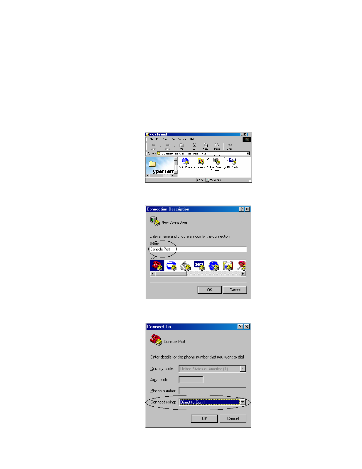
1. Select Start->Programs->Accessories->HyperTerminal
2. Enter a connection name and click OK
3. Select properly COM port and click OK
18
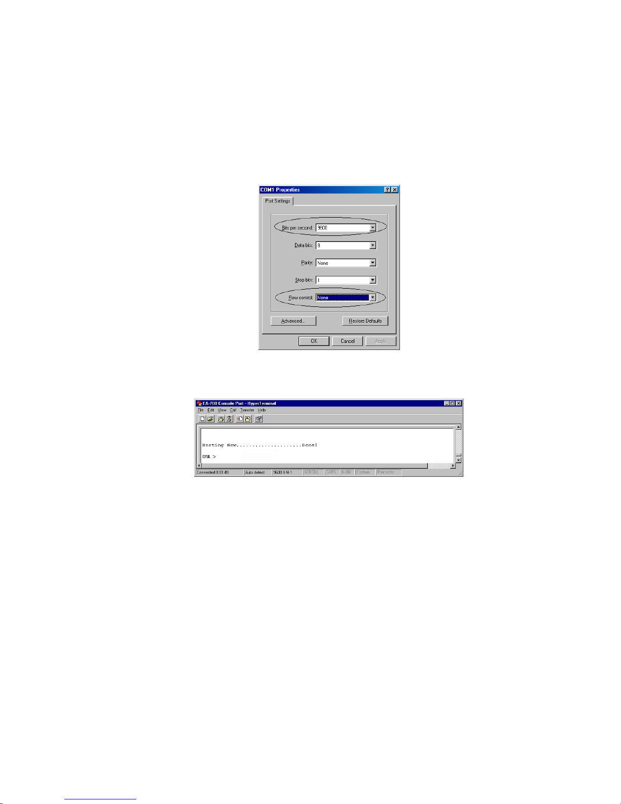
4. Enter the following parameters :
Bits per second 9600
Data bits 8
Parity None
Stop bits 1
Flow Control None
Then click OK
6. When the HyperTerminal window appears, you must press the enter key several time to get
the command prompt for the Router’s command line interface.
7. Now you are ready to configure the Router by using command. Please contact your ISP/NSP
to obtain the detail command sets of your Router. If the Router does not return any message,
refer to Appendix B for troubleshooting information.

19
Chapter 3 Basic Configurations
This chapter contains configuration information, instructions and examples for the basic link protocols
that supported by the ADSL Router. The information needed to configure the Router is depending on
the chosen link protocol. The link protocol is determined by your NSP(Network Service Provider).
Therefore, It is necessary to know the link protocol which your NSP support before you refer to the
configuration information that will apply to your setup.
3.1 Factory default configuration
The Router is shipped with factory default settings. You may or may not need to change them depend
on what kind of network that your Router is going to be installed.
Configuration item Default settings of ADSL Router
Ethernet Interface IP address 192.168.7.1
Network Mask 255.255.255.0
ADSL interface IP address None
Network Mask None
ATM VPI/VCI number 0/33
Data Encapsulation Protocol RFC1483
Machine Name
*DSL
Domain name Disabled
DHCP Server Supported by Some Models
DHCP Client Supported by Some Models
DNS Relay Supported by Some Models
NAT Disabled
RIP Disabled
IP filtering Disabled
Bridge filtering Disabled
Spanning Tree Disabled
Telnet login password
*DSL
SNMP access password
*DSL
* ”DSL” for example in here, instead of your machine name and password they are same as your
ADSL Router’s Model.
Model names are: EA701, EA710, EA715
20
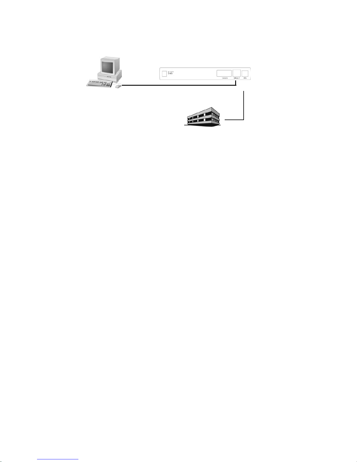
3.2 Bridged RFC1483
(Default configuration for Router)
[System configuration]
[ISP/DSLAM configuration]
IP address : 192.168.7.3
Subnet mask : 255.255.255.0
Gateway : None
[Local PC configuration]
IP address : 192.168.7.2
Subnet mask : 255.255.255.0
Gateway : None
The Router already default to support the RFC 1483. However, you can use following
procedure to reconfigure the Router to support the RFC 1483 again.
> ip device flush
> bridge device add edd
> bridge device add bun/port=r1483/rfc1483=true/mode=<x>/
txvpi=<y>/txvci=<z>/rxvpi=<y>/rxvci=<z>
(<x> is the encapsulation mode of RFC1483, it can be one of LlcBridged and VcMuxBridged, and the setting of
encapsulation mode is case sensitivity. <y> is the VPI value, and <z> is the VCI value)
> config save
> restart
The following describes how to remove all configurations properly so that we start from a fresh
configuration.
> isfs rm resolve↵
> isfs rm initbridge↵
> isfs rm initppp↵
> restart ↵
DSLAM/NSP
192.168.7.3
Ethernet Port
10Base-T Port
192.168.7.1
192.168.7.2
//r1483
//
r1483
21
3.3 Routed RFC1483
[System configuration]
[ISP/DSLAM configuration]
IP address : 10.99.48.1
Subnet mask : 255.255.255.0
Gateway : 10.99.48.50
[Local PC A configuration]
IP address : 10.107.1.130
Subnet mask : 255.255.255.248
Gateway : 10.107.1.129
[Local PC B configuration]
IP address : 10.107.1.131
Subnet mask : 255.255.255.248
Gateway : 10.107.1.129
> home ↵
(ignores any error message, just ensures back to root prompt)
> ip device add ethernet ether //edd 10.107.1.129 ↵
(set 10.107.1.129 as the IP address for your ADSL Router)
> ip device add mpoa ptp //bun/port=r1483/rfc1483=true/mode=<x>/
txvpi=<y>/txvci=<z>/rxvpi=<y>/rxvci=<z> 10.99.48.50↵
(assume 10.99.48.50 is the static IP address assigned by your service provider for the PC); (<x> is the
encapsulation mode of RFC1483, it can be one of LlcRouted and VcMuxRouted, and the setting of encapsulation
mode is case sensitivity. <y> is the VPI value, and <z> is the VCI value)
> ip route add default 0.0.0.0 10.99.48.1 0:0:0:0 ↵
(10.99.48.1 is the IP address of your service provider)
> ip relay all↵
(enable routing between rfc1483 and ethernet ports)
config save ↵
restart ↵
You can use following procedure to remove existing RFC 1483 setting.
> isfs rm resolve↵
> isfs rm initbridge
↵
> isfs rm initppp↵
> restart ↵
DSLAM/ISP
Ethernet Port
10.107.1.130
10Base-T Port
Up-Link
PC A
PC B
PC C
PC N
HUB
10.107.1.131
10.107.1.132
10.107.1.129
10.99.48.50
10.99.48.1
22
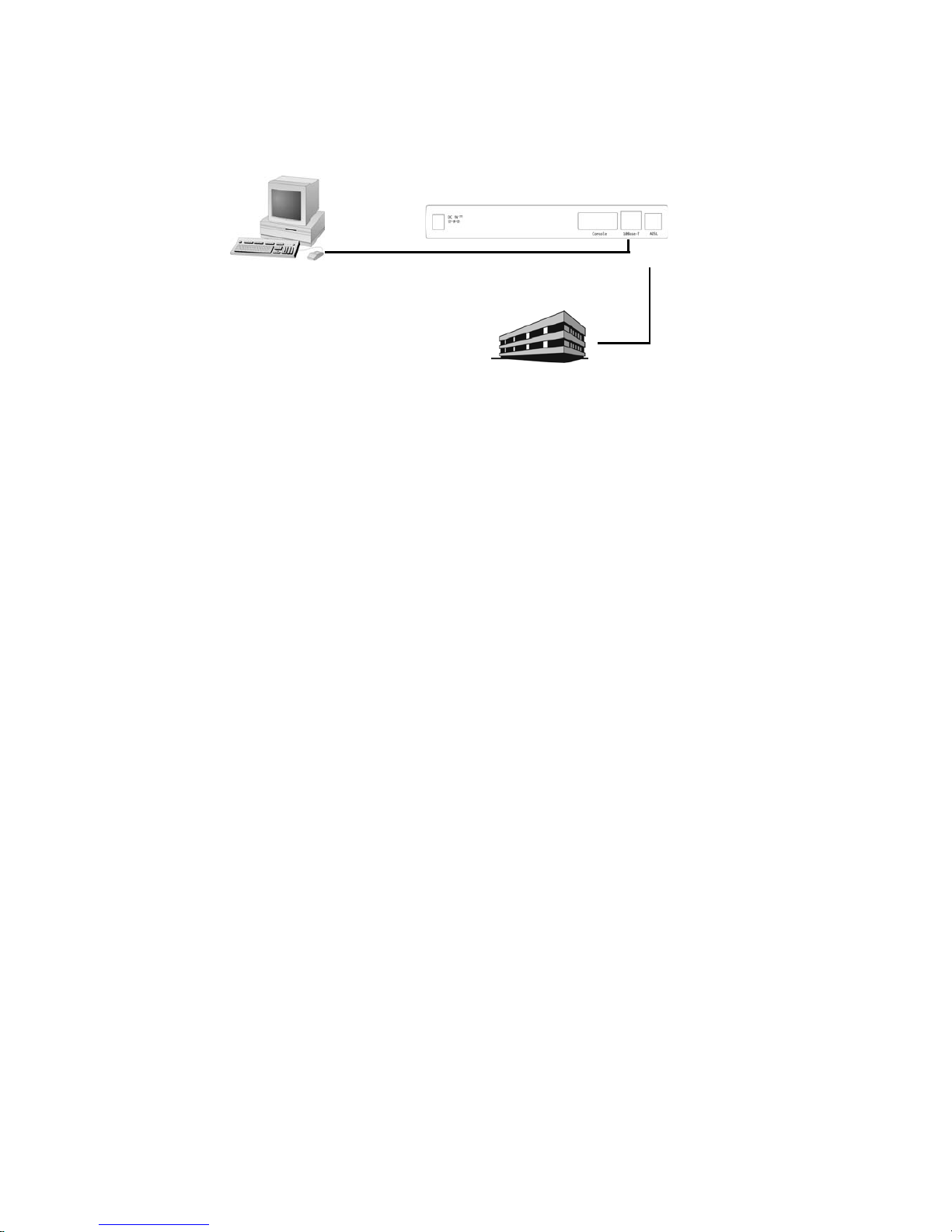
3.4 Classical IP (RFC1577)
[System configuration]
[ISP/DSLAM Configuration]
IP Address : 192.168.1.1
Subnet Mask : 255.255.255.0
Default Gateway : 192.168.1.2
[Local PC Configuration]
IP Address : 202.1.136.100
Subnet Mask : 255.255.255.0
Default Gateway : 202.1.136.254
The following describes how to remove all configurations properly so that we start from a fresh
configuration.
Remove all existing bridge module configuration
> home ↵
> config reset bridge ↵
> config save ↵
> restart ↵
Remove all existing router module configuration
> home ↵
> ip device flush ↵
> ip norelay
↵
> ip ipatm pvc delete ipoa r1483 0/32 ↵
(use the same VPI/VCI of RFC 1577 setting)
> config save ↵
> restart
↵
Remove all existing IP module configuration device
> home ↵
> ip device flush ↵
> config save ↵
> restart ↵
We are ready for RFC1577 setup
DSLAM/NSP
192.168.1.1
Ethernet Port
10Base-T Port
202.1.136.100
202.1.136.254
192.168.1.2

23
Specify the gateway (RFC1577 on ISP/DSLAM site and Ethernet on local PC site)
> home ↵
> ip device add ethernet ether //edd 202.1.136.254 ↵
> ip device add ipoa atm //atm 192.168.1.2 ↵
> config save ↵
> restart ↵
Enable forwarding between router interface
> home ↵
> ip relay all ↵
> ip ipatm pvc add ipoa r1483 x/y remoteip 192.168.1.1 ↵
(‘ x’ is the VPI, ‘ y’ is the VCI. Check with your service provider)
> config save ↵
> restart ↵

24
3.5 PPP Over ATM (RFC2364)
[System configuration]
[ISP/DSLAM Configuration]
IP Address : 192.168.1.1
Subnet Mask : 255.255.255.0
Default Gateway : 192.168.1.2
[Local PC Configuration]
IP Address : 202.1.136.100
Subnet Mask : 255.255.255.0
Default Gateway : 202.1.136.254
The ADSL Router also can be setup to support RFC 2364(PPP over ATM) with following procedure.
Before setup RFC 2364, you have to ensure remove existing RFC 1483 or RFC 1577 configuration with
the procedure mentioned above.
• IP dial out over PPPoA
> ip device add Ethernet ether //edd 202.1.136.254 ↵
(This is the IP of Ethernet port of ADSL Router)
> ip device add ppp_device ether //ppp/DEVICE=1 ↵
> config save ↵
> restart ↵
> ppp 1 pvc 0 32 ↵
(Set channel 1 to VPI=0, VCI=32)
> ppp 1 welogin <name> <password> ↵
(This is the login name and password of PPP server)
> ppp 1 enable ↵
> config save ↵
> restart ↵
> ip relay all ↵
> config save ↵
> restart ↵
• Remote bridging over PPPoA
> bridge device add edd ↵
> bridge device add ppp/DEVICE=2 ↵
> config save ↵
> restart ↵
> ppp 1 pvc 32 mac ↵
> ppp 1 interface 2 ↵
> ppp 1 enable ↵
> restart ↵
DSLAM/NSP
192.168.1.1
Ethernet
10Base-T Port
202.1.136.100
202.1.136.254
192.168.1.2
DSLAM/ISP2

25
The RFC 2364 configuration also can be removed by following procedure. Please ensure to remove the
RFC 2364 configuration before set the ADSL Router to other configuration.
• IP dial out over PPPoA
> ip device flush ↵
> config save ↵
> restart ↵
> ppp 1 pvc none ↵
> ppp 1 welogin none ↵
> ppp 1 interface 0 ↵
> ppp 1 disable ↵
> restart ↵
> ip norelay ↵
> config save ↵
> restart ↵
• Remote bridging over PPPoA
> config reset bridge ↵
> config save ↵
> restart ↵
> ppp 1 pvc none ↵
> ppp 1 interface 0 ↵
> ppp 1 disable ↵
> restart ↵
26
3.6 PPP Over Ethernet (RFC2516)
*Supported by firmware version 2.0 and above!
[System configuration]
[ISP/DSLAM Configuration]
IP Address : 192.168.1.1
Subnet Mask : 255.255.255.0
Default Gateway : 192.168.1.2
[Local PC Configuration]
IP Address : 202.1.136.100
Subnet Mask : 255.255.255.0
Default Gateway : 202.1.136.254
The ADSL Router also can be setup to support RFC 2516(PPP over Ethernet) with following procedure.
Before setup RFC 2516, you have to ensure remove existing RFC 1483 or RFC 1577 or RFC 2364
configuration with the procedure mentioned above.
• IP dial out over PPPoE
> ip device add ethernet ether //edd 202.1.136.254 ↵
(This is the IP of Ethernet port of ADSL Router)
> ip device add ppp_device ether //ppp/DEVICE=1 ↵
> ppp 1 pppoe 0 32 ↵
(Set channel 1 to VPI=0, VCI=32)
> ppp 1 welogin <name> <password> chap↵
(This is the login name and password of PPP server)
> ppp 1 enable ↵
> config save ↵
> restart ↵
> ip relay all ↵
> config save ↵
> restart ↵
The RFC 2516 configuration also can be removed by following procedure. Please ensure to remove the
RFC 2516 configuration before set the ADSL Router to other configuration.
> isfs rm resolve
> isfs rm initppp
> restart
DSLAM/NSP
192.168.1.1
Ethernet
10Base-T Port
202.1.136.100
202.1.136.254
192.168.1.2
DSLAM/ISP
2
27
Chapter 4 Advanced Configurations
This Chapter described the advanced features that are primarily intended for experienced users and
network administrators to perform network management and more complex configurations.
4.1 Add NAT to Classic IP, PPP over ATM or PPP over Ethernet
NAT is an IP address conversion feature that translates a PC’s local (internal) address into a temporary
global (outside/Internet) IP address. NAT is needed when a PC (or several PCs) on a Local Area
Network wants to connect to the outside Internet to get to a remote network: NAT swaps the local IP
address to a global IP address. Our version of NAT goes one step further by allowing several PCs to
share one single IP address to the Internet, thus reducing connection costs. In effect, it allows a whole
LAN to connect to the Internet as a single user.
[System configuration]
[ISP/DSLAM configuration]
IP address : 192.168.102.3
Subnet mask : 255.255.255.0
Gateway : None
[Local PC 1 configuration]
IP address : 202.1.136.101
Subnet mask : 255.255.255.0
Gateway : 202.1.136.254
[Local PC 8 configuration]
IP address : 202.1.136.108
Subnet mask : 255.255.255.0
Gateway : 202.1.136.254
The following command tell you how to adding a Network Address Translation protocol to the Classic
IP(RFC1577) or PPP over ATM(RFC2364) or PPP over Ethernet(RFC2516) configuration that mentioned
above. The following command must be added after the “ip device add …” commands have been
given and the Router restarted.
Enables NAT on a Classic IP (RFC1577)
> ip nat add ipoa ↵
Enables NAT on a PPP over ATM (RFC2364) or PPP over Ethernet (RFC2516)
> ip nat add ppp_device ↵
DSLAM/NSP
Ethernet Port
10Base-T Port
Up-Link
PC 1
202.1.136.101
HUB
PC 8
202.1.136.108
28
4.2 Enables NAT to RFC1483, Classic IP (RFC1577), PPP over ATM
(RFC2364), PPP over Ethernet (RFC2516) in Routing mode
The ADSL modem can be setup to adding NAT protocol to a Routing Mode configuration like
RFC1483, RFC 1577, RFC 2364 or RFC 2516 with following procedure. The following procedure must
be typed after
ip device add command ( in RFC1483, RFC 1577, RFC 2364 or RFC2516 configure
procedure) have been given and the ADSL Router restarted.
[System configuration]
[ISP/DSLAM configuration]
IP address : 192.168.102.3
Subnet mask : 255.255.255.0
Gateway : 192.168.102.2
[Local PC 1 configuration]
IP address : 202.1.136.1
Subnet mask : 255.255.255.0
Gateway : 202.1.136.254
[Local PC 8 configuration]
IP address : 202.1.136.100
Subnet mask : 255.255.255.0
Gateway : 202.1.136.254
• Add NAT to RFC 1483 to above RFC 1483 Routing Mode example
> ip nat add mpoa ↵
(ipoa is the device name same as you configure in RFC 1483 example)
• Remove NAT to RFC 1483 to above RFC 1483 Routing Mode example
> ip nat delete mpoa ↵
• Add NAT to RFC 1577 to above RFC 1577 Routing Mode example
> ip nat add ipoa ↵
(ipoa is the device name same as you configure in RFC 1577 example)
• Remove NAT to RFC 1577 to above RFC 1577 Routing Mode example
> ip nat delete ipoa ↵
• Add NAT to RFC 2364/RFC2516 to above RFC 2364/RFC2516 Routing Mode example
> ip nat add ppp_device ↵
DSLAM/NSP
Ethernet Port
10Base-T Port
Up-Link
PC 1
202.1.136.1
HUB
PC N
202.1.136.100
202.1.136.254
192.168.102.2
192.168.102.3
 Loading...