


TW-EA510v4
ADSL2+ WLAN 802.11g
VPN Firewall Router
User’s Manual

Table of Contents
CHAPTER 1: INTRODUCTION..........................................................................................................3
INTRODUCTI ON T O YOUR RO UTER ..........................................................................................................3
FEATURES .............................................................................................................................................3
TW-EA510
CHAPTER 2: INSTALLING THE ROUTER......................................................................................7
I
MPORTANT NO TE FO R USING THIS ROUT E R.............................................................................................7
PACKAGE CONTENTS .............................................................................................................................7
THE FRONT LEDS .................................................................................................................................8
THE REAR PORTS ..................................................................................................................................9
CABLING.............................................................................................................................................10
CHAPTER 3: BASIC INSTALLATION.............................................................................................11
CONNECTI NG YO UR ROUT ER ................................................................................................................11
FACTORY DEFAULT SETTINGS .............................................................................................................16
Web Interface (Username and Password).......................................................................................16
LAN Device IP Settings...................................................................................................................16
ISP setting in WAN site...................................................................................................................16
DHCP server..................................................................................................................................16
LAN and WAN Port Addresses........................................................................................................ 16
INFORMATION FROM YOUR ISP............................................................................................................17
CONFIGURING WITH YOUR WEB BROWSER ........................................................................................... 18
V4 ADSL ROUTER APPLICATION.........................................................................................6
CHAPTER 4: CONFIGURATION .....................................................................................................19
STATUS...............................................................................................................................................20
ARP Table......................................................................................................................................20
Wireless Association Table............................................................................................................. 20
Routing Table.................................................................................................................................21
DHCP Table................................................................................................................................... 21
PPTP Status ................................................................................................................................... 23
Email Status ...................................................................................................................................23
Event Log.......................................................................................................................................24
Error Log.......................................................................................................................................24
NAT Sessions..................................................................................................................................25
Diagnostic......................................................................................................................................25
UPnP Port m a p............................................................................................................................... 26
QUICK START......................................................................................................................................27
CONFIGURATION .................................................................................................................................29
LAN (Local Area Network).............................................................................................................29
Bridge Interface ..........................................................................................................................29
Ethernet ......................................................................................................................................30
IP Alias .......................................................................................................................................30
Ethernet Client Filter...................................................................................................................31
Wireless......................................................................................................................................32
Wireless Security........................................................................................................................34
Wireless Client Filter...................................................................................................................36
Port Setting.................................................................................................................................37
DHCP Server ..............................................................................................................................38
WAN (Wide Area Network)............................................................................................................. 39
ISP .............................................................................................................................................39
Table o f Co nt e nts i

DNS............................................................................................................................................48
ADSL..........................................................................................................................................49
System ............................................................................................................................................51
Time Zone..................................................................................................................................51
Remote Access ..........................................................................................................................52
Firmware Upgrade......................................................................................................................52
Backup / Restore........................................................................................................................53
Restart Router ............................................................................................................................53
User Management......................................................................................................................54
Firewall and Access Control...........................................................................................................55
General S et t ings.........................................................................................................................56
Packet Filter................................................................................................................................57
Intrusion Detection......................................................................................................................64
URL Filter...................................................................................................................................66
IM / P2P Blocking.......................................................................................................................68
Firewall L og ................................................................................................................................69
VPN (Virtual Private Networks)......................................................................................................70
PPTP (Point -to-Poi nt T unneling Protocol)...................................................................................70
QoS (Quality of Service).................................................................................................................78
Prioritization................................................................................................................................78
Outbound IP Throttling (LAN to WAN) ........................................................................................80
Inbound I P T hrottling (W AN to LAN) ...........................................................................................81
Virtual Server (“Port Forwarding”)............................................................................................... 85
Add Virtual Server.......................................................................................................................86
Edit DMZ Host............................................................................................................................88
Edit One-to-One NAT (Network Address Translation).................................................................89
Time Schedule................................................................................................................................92
Configuration of Time Schedule ..................................................................................................93
Advanced........................................................................................................................................94
Static Route................................................................................................................................94
Dynamic DNS.............................................................................................................................95
Check Email ...............................................................................................................................96
Device Management...................................................................................................................97
IGMP........................................................................................................................................101
VLAN Bridge.............................................................................................................................101
Mail Alert for WAN IP................................................................................................................105
SAVE CONFIGURATION TO FLASH ......................................................................................................106
LOGOUT............................................................................................................................................106
CHAPTER 5: TROUBLESHOOTING............................................................................................. 107
PROBLEMS S T ARTING UP THE RO UTER ................................................................................................107
PROBLEMS WIT H THE WAN INTERFACE ............................................................................................. 107
PROBLEMS WIT H THE LAN INTERFACE ..............................................................................................108
APPENDIX A: PRODUCT SUPPORT AND CONTACT INFORMATION..................................109
Table o f Co nt e nts iii

TW-EA510 version 4 ADSL2+, WLAN 802.11g, VPN, Firewall Router
Chapter 1: Introduction
Introduction to your Router
Welcome to the TeleWell TW-EA510v4 Router. The router is an “all-in-one” unit, combining an ADSL
modem, IEEE 802.11g wireless access point, ADSL router with four-port 10/100M auto-crossover
Switch, a nd Fire wall, ena bling y ou to m aximiz e the pot ential of your existin g resourc es. The T W-EA5 10
version 4 can provide everything you need to get the machines on your network connected to the
Internet ov er y our A DSL b roadb an d co nnec tio n. It supp orts t he lat es t A DSL 2/2 + tech nology en ab ling u p
to and beyond ADSL2+ wire-speed. Its powerful QoS feature for traffic priority and bandwidth
management makes the device a perfect mate to the office user.
Access Po int in t his device, t he router brin gs up t he productiv it y and mobil it y t o of f ic e us ers .
With featur es suc h as an A DSL Qu ick-St art wizar d and DHCP S erv er, you c an be onli ne in no ti me at all
and with a minimum of fuss and configuration, catering for first-time users to the guru requiring
advance d f eat ures and control over t heir Internet connec t ion and netw ork.
Features
With integrated 54Mbps 802.11g
Express I nternet Access
The router complies with ADSL worldwide standards. It supports downstream rate up to 12/24
Mbps with ADSL2/2+, 8Mbps with ADSL. Users enjoy not only high-speed A DSL se rvic es but also
broadband multimedia applications such as interactive gaming, video streaming and real-time
audio muc h easier and faster th an ever. It is compliant w ith Multi-Mode stan dard (ANSI T1.41 3,
Issue 2; G.d mt (ITU G.992.1); G.lite (ITU G.99 2.2); G.hs (ITU G9 94.1); G.dmt. bis (ITU G.992.3 );
G.dmt.bisplus (IT U G.992.5)).
Virtual Private Network (VPN)
It allows user t o make a t unnel with a re mote site directly to secu re the dat a transmiss ion amon g
the connect ion. User can use e mbedde d PPTP client/serv er which is supporte d by this router to
make a VP N connection or us ers can run the PPTP client in P C and the router alr eady provides
PPTP pass t hrough f unction t o establis h a VPN c onnect ion if the us er likes to ru n the PP TP client
in his local computer.
802.11g Wirel ess A P with WP A Support
With integrat ed 802.11g Wire less Access Poi nt in the router, the devic e offers a quick an d easy
access among wired network, wireless network and broadband connection (ADSL) with single
device sim plicity , an d as a res ult, mobil ity t o the users . In addit ion t o 54 M bps 8 02. 11g dat a rat e, it
also interoperates backward with existing 802.11b equipment. The Wireless Protected Access
(WPA) and W ireless Encrypt ion Protocol (W EP) supported f eatures enhanc e the security level of
data protect ion and ac c es s c ont rol via Wireless LAN.
Fast Ethernet Switch
A 4-port 10/100Mbps fast Ethernet switch is built in with automatic switching between MDI and
MDI-X for 10Base- T and 100Bas e-TX port s. An Ethe rnet straig ht or crossov er cable ca n be used
directly for aut o detecti on.
Multi -Protocol t o Est abli s h A Connec t ion
It support s PPPoA (R F C 2364 - PPP over A T M A daptation Layer 5), RFC 148 3 encapsulation ove r
ATM (bridged or routed) and PPP over Ethernet (RFC 2516) to establish a connection with the
ISP. The product als o s upports VC-based and LLC- based mult iplexing.
3
Chapte r 1 : In tr od uctio n

TW-EA510 version 4 ADSL2+, WLAN 802.11g, VPN, Firewall Router
Quick Installation Wizard
It support s a WEB GUI page t o install t his device quickly. With this wizard, end use rs c an enter the
information easily w hich they g et f rom their ISP, t hen surf th e I nt ernet imme diately.
Universal Plug and Play (UPnP) and UPnP NAT Traversal
This protoc ol is used t o enable si mple and rob ust connect ivity among s tand-alone devices an d
PCs from many different vendors. It makes network simple and affordable for users. UPnP
architect ure lev erag es T CP/I P and the Web to en abl e sea mless proxi mity network i ng in addit ion t o
control and data transfer among networked devices. With this feature enabled, users can now
connect t o N et m eet ing or MS N M es s enger sea m lessly.
Net work A ddres s Transl ati o n (NAT)
Allows multi-users to access outside resources such as the Internet simultaneously with one IP
address/o ne Internet ac cess acc ount. Many ap plication lay er gateway ( ALG) are sup ported suc h
as web browser, ICQ, FTP, Telnet, E-mail, News, Net2phone, Ping, NetMeeting, IP phone and
others
SOH O Firewall Security with DoS a n d S PI
Along with the built-in NAT natural firewall feature, the router also provides advanced hacker
pattern-filt ering protection. I t can automatically d etect and block Denial of Service (DoS) attack s.
The router is built with Stateful Packet Inspection (SPI) to determine if a data packet is allowed
through th e f irewall to th e private LAN.
Domain Name System (DNS) relay
It provides an easy way to map the domain name (a friendly name for users such as
www.yahoo.com
) and IP address. When local machine sets its DNS server with this router’s IP
address, ev ery DNS conv ersion request packet from the P C to this router wi ll be forwarded t o the
real DNS in the outside net work.
Dynamic Domain Name System (DDNS)
The Dynamic DNS service allows you to alias a dynamic IP address to a static hostname. This
dynamic I P address is t he WAN IP a ddress. For example, t o us e t he servic e, y ou must firs t apply f or
an account from a DDNS service like http://www.dyndns.org/
. More than 5 DDNS servers are
supported.
Quality of Service (Q oS )
QoS gives you full c ontrol ov er which types of o utgoing data traff ic should b e given p riority by t he
router, ensuring important data like gaming packets, customer information, or management
informatio n mov e thro ugh the router ay lightn ing speed, ev en un der heav y loa d. The Q oS feat ures
are config urable by sou rce IP addr ess, destin ation IP addres s, protoco l, and port. Y ou can thrott le
the spee d at which diff erent types of outgoing d ata pass thro ugh the rout er, to ensure P2P users
don’t saturate upload bandwidth, or office browsing doesn’t brin g client web serving to a halt. In
addition, or alter nativ ely, you can s im ply cha ng e the pri ority of differ ent t ypes of uplo ad d ata an d let
the router sort out the act ual spee ds .
Virtu al Server (“ p ort forwar ding”)
Users ca n specify s ome s ervices t o be v isible fro m outsid e users . The ro uter c an detect inco ming
service req uests an d forw ard eithe r a single p ort or a ra nge of po rts to the s pecific l ocal com puter
to handle it . For example, a user can as sign a PC in th e LAN actin g as a WEB serv er inside an d
expose it t o the outs ide net work. Outsi de users c an browse i nside we b servers directly while it is
protected by NAT. A DM Z host setting is also provide d to a local com puter expos ed to the out side
network, Internet.
4
Chapte r 1 : In tr od uctio n

TW-EA510 version 4 ADSL2+, WLAN 802.11g, VPN, Firewall Router
Rich Packet Filtering
Not only filters the packet based on IP address, but also based on Port numbers. It will filter
packets from and to t he I nt ernet, and also provides a hig her level of security control.
Dynamic Host Configuration Protocol (DHCP) client and server
In the WAN site, the DHCP client can get an IP address from the Internet Service Provider (ISP)
automatically. In the LAN site, the DHCP server can allocat e a range of client IP a ddresses an d
distribute t hem including IP ad dres s , s ubnet mas k as w ell as DNS IP ad dress to local comput ers . I t
provides a n easy way t o manage the local IP network.
Static and RIP1/2 Routing
It has routin g c apability and supp ort s eas y s t at ic routing table or RIP1/ 2 routing p rot ocol.
Si m ple Ne tw or k Ma na ge m e nt Pr ot oc ol (S NM P)
It is an easy w ay t o remotely m anage the r out er v ia SNMP.
Web based GUI
It supports web based G UI for configurati on and manag ement. It is user-friendly and c omes with
on-line help. It also supports remote management capability for remote users to configure and
manage t his product.
Firmware Upgradeable
Device ca n be upgrade d to the latest firmwar e t hrough the W EB based G UI.
Rich management interfaces
It supports f lexi ble m anag e ment int erf aces with lo cal cons ole p ort, LAN port, an d WAN port . Users
can use terminal applications through the console port to configure and manage the device, or
Telnet, W EB GUI, and SNMP thro ugh LAN or W AN ports to c onf igure and manage the device.
5
Chapte r 1 : In tr od uctio n
TW-EA510 version 4 ADSL2+, WLAN 802.11g, VPN, Firewall Router
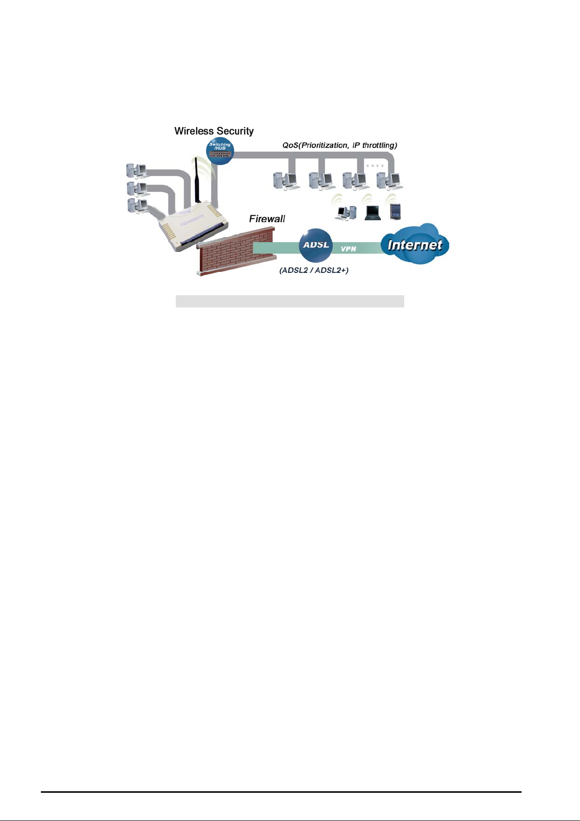
TW-EA510v4 ADSL Router Application
Figure 1.1 Application Diagra m of TW-EA510v4
Thank you for your purchase, and welc ome t o the world of broadba nd Int e rne t
6
Chapte r 1 : In tr od uctio n
TW-EA510 version 4 ADSL2+, WLAN 802.11g, VPN, Firewall Router
g
Import a nt no te for us i n g thi s ro ut er
Do n ot use this rout e r in high humidity or high t e mperatures.
Do not use the same power source for this router as other
equipment.
Warnin
Do not open or repair the case yourself. If this router is too hot,
turn off the power imme diat ely and hav e it repaire d at a qualified
service c enter.
Avoid using this product and all accessories outdoors.
Attention
Place this router o n a s table surface.
Only use the power adapter t ha t comes with the pac kage. Usin g
a differen t voltage rating pow er adaptor may dama ge t his router.
Package Contents
802.11g AD SL2+ Fire wall Ro uter
Chapter 2: Installing the Router
RJ-11 ADSL/telephone Cable
Ethernet (CAT-5 LAN) Cable
RJ-45 to RS-232 Console Kit
AC-D C p ower adapter (12VD C, 1A)
A detachable antenna
Manual
Chapter 2: Installing the router
7

The Front LE D s
LED Meaning
1 Internet
TW-EA510 version 4 ADSL2+, WLAN 802.11g, VPN, Firewall Router
Lit green w hen IP connected.
Flashes green when IP connected and IP traffic is passing thru the
device.
Lit red whe n dev ice atte m pt ed t o become I P c onnected and faile d.
2 DSL
Ethernet Port
3
4
5 Mail Lit and flashed periodically wh en t here is e mai l in the Inbox .
6 Power
1X — 4X
(RJ-45 connector)
Wireless
Lit green when successfully connected to an ADSL DSLAM
(“linesync”).
Lit when the LAN link is c onnected t o an Ethernet device.
Green for 100Mbps; Orange for 10Mbps.
Blinking w hen data is T ransmitted / R ec eived.
Lit green w hen the wireles s c onnection is estab lished.
Flashes w hen sendi ng/ receiving data.
Flashes at 1Hz when WP S is ac t iv e.
Lit green w hen power o n.
Lit red when POST(Power On Self Test) failure (not bootable) or
device malfu nctio n.
8
Chapter 2: Installing the router
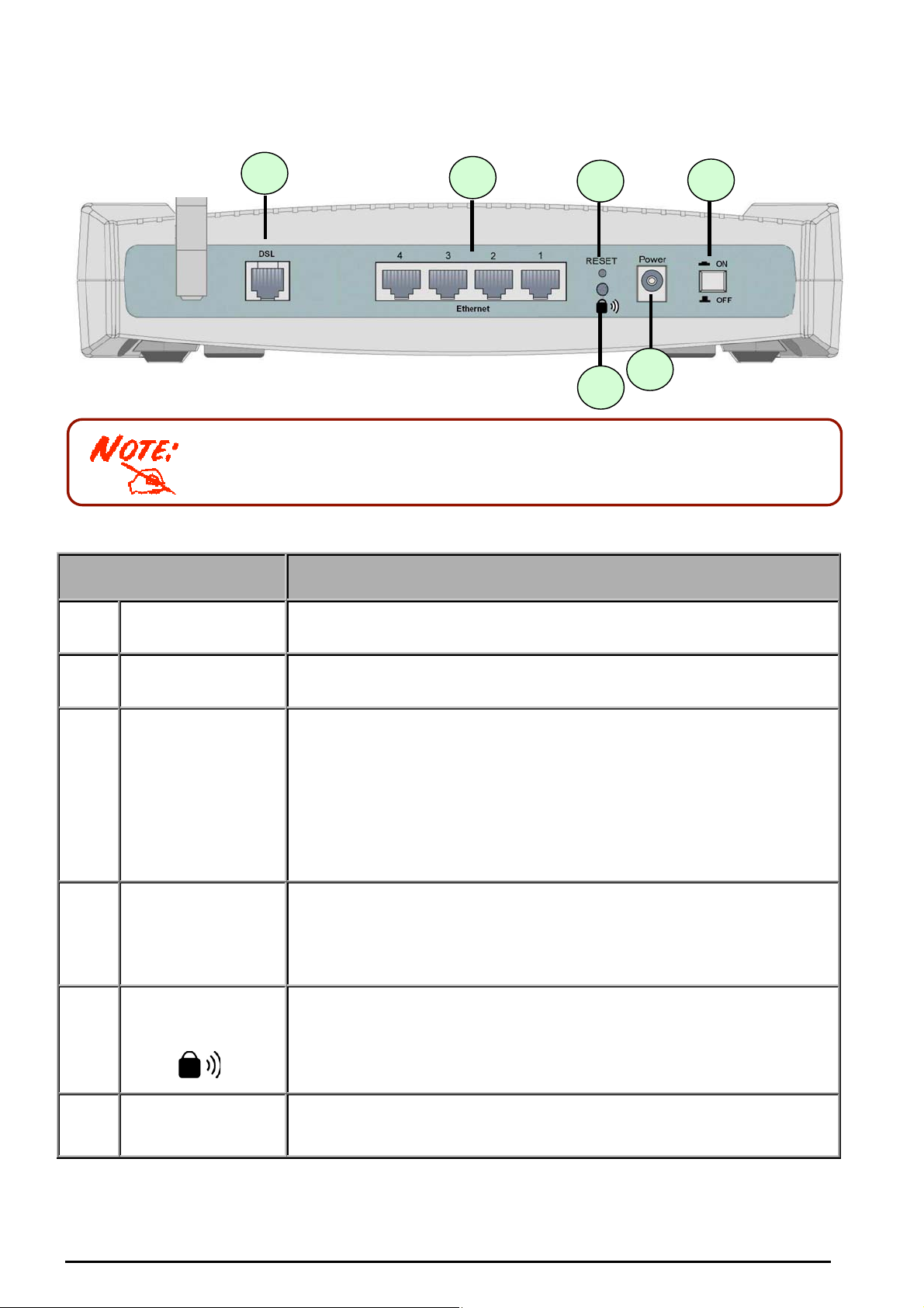
The Rear Ports
1 3 4
The Ethernet Port # 4 can be used as a console port. You need a special
console tool that already includes in the package to connect with LAN port 4
and PC’s RS -232 port (9- pin serial p ort ).
TW-EA510 version 4 ADSL2+, WLAN 802.11g, VPN, Firewall Router
6
5
2
Port Meaning
1
2
3 RESET
4
5
Power Switch
Power
Ethernet Port
1X — 4X
(RJ-45 connector)
WPS Push Butt on
Power ON/OFF switch
Connect t he s upplied power ada pt er t o t his jack.
To be sure the device is being turn ed on press RESET button for:
1-3 seconds: quick reset the dev ice.
6 seconds above, and power off, power on the device: restore to
factory default settings. (Cannot login to the router or forgot your
Userna me/Passw ord. Press the b ut t on f or more than 6 seconds ).
Caution: After pressing the RESET button for more than 6 seconds, to be
sure you power cycle the device again.
Connect a UTP Ethernet cable (Cat-5 or Cat-5e) to one of the four
LAN ports when connecting to a PC or an office/home network of
10Mbps o r 100Mbps.
Caution: Port 4 can be either a LAN or Console port at a time but not both.
WPS (Wi-Fi Protected Setup) is designed to ease set up of securityenabled Wi -Fi networks in t he home a nd small office environment.
Note: This feature is suppted later by software update. Press WPS Push
Button to acti v ate W PS featu r e .
6
DSL
Connect the supplied RJ-11 (“telephone”) cable to this port when
connecting to the AD SL/ t elephone network .
Chapter 2: Installing the router
9

TW-EA510 version 4 ADSL2+, WLAN 802.11g, VPN, Firewall Router
Cabling
One of the most common causes of problems is bad cabling or ADSL line(s). Make sure that all
connected devic es are tur ned on. On t he front of the pr oduc t is a bank of LE Ds. V erify t hat the L A N Link
and ADSL line LEDs are lit. If t hey are not, verify t hat y ou are usin g t he proper ca bles.
Ensure that al l other devices connect ed to the same t elephone line as your router (e. g. telepho nes, fax
machines, analogue modems) have a line filter connected between them and the wall socket (unless
you are using a Central Splitter or Central Filter installed by a qualified and licensed electrician), and
ensure that a ll lin e filters are c orrec tly ins tall ed an d the rig ht w ay ar ound. Miss ing lin e filt ers o r line f ilters
installed the wrong way around can cause problems with your ADSL connection, including causing
frequent d is c onnections .
Chapter 2: Installing the router
10

TW-EA510 version 4 ADSL2+, WLAN 802.11g, VPN, Firewall Router
Chapter 3: Basic Installation
The router can be configured with your web browser. A web browser is included as a standard
application in the following operating systems: Linux, Mac OS, Windows 98/NT/2000/XP/Me, etc. The
product pr ov ides a very eas y and user-friendly interface fo r c onf iguratio n.
Please ch eck your P C’s net work co mponents . The T CP/IP pr otocol stac k and Eth ernet net work a dapter
must be installed. If not , please refer t o y our Wind ows-relate d or other op erat ing system manuals.
There are ways to connect with the router, either through an external repeater hub to the router or
directly connecting with PCs. However, to be sure PCs have an Ethernet interface installed properly
prior to connecting to the router device. You ought to configure your PCs to obtain an IP address
through a DH CP serv er or a f ix ed IP a ddres s th at m ust be i n the s am e su bnet as the r oute r. The def ault
IP address of the router is 192.168.0.254 an d the subnet mask is 255.255.255.0 (i.e. any att ached PC
must be in the sa me sub net, an d have a n IP addr ess in the rang e of 192.168.0.1 to 192.168.0.253). The
best and easiest way is to configure the PC to get an IP address automatically from the router using
DHCP. If you encounter any problem accessing the router’s web interface it may also be advisable to
uninstall any kind of software firewall on your PCs, as they can cause problems accessing the
192.168.0.254 IP address of the router. Users sh ould mak e their own d ecisions o n how to bes t protec t
their net work.
Please foll ow the steps below for y our PC’s net w ork environment ins t allation.
Any TCP/IP capable workstation can be used to communicate with or
through the router. To configure other types of workstations, please consult
the manufacturer’s documentation.
Connecting your router
1. Connect t his router to a LAN (Local Area N et w ork ) and the A D SL/ t elephone (ADSL) network.
2. Power o n t he device.
3. Make sur e t he Power LED is lit green stea dily and that th e LAN LED is lit.
Chapter 3: Basic Insta lla tion
11
TW-EA510 version 4 ADSL2+, WLAN 802.11g, VPN, Firewall Router
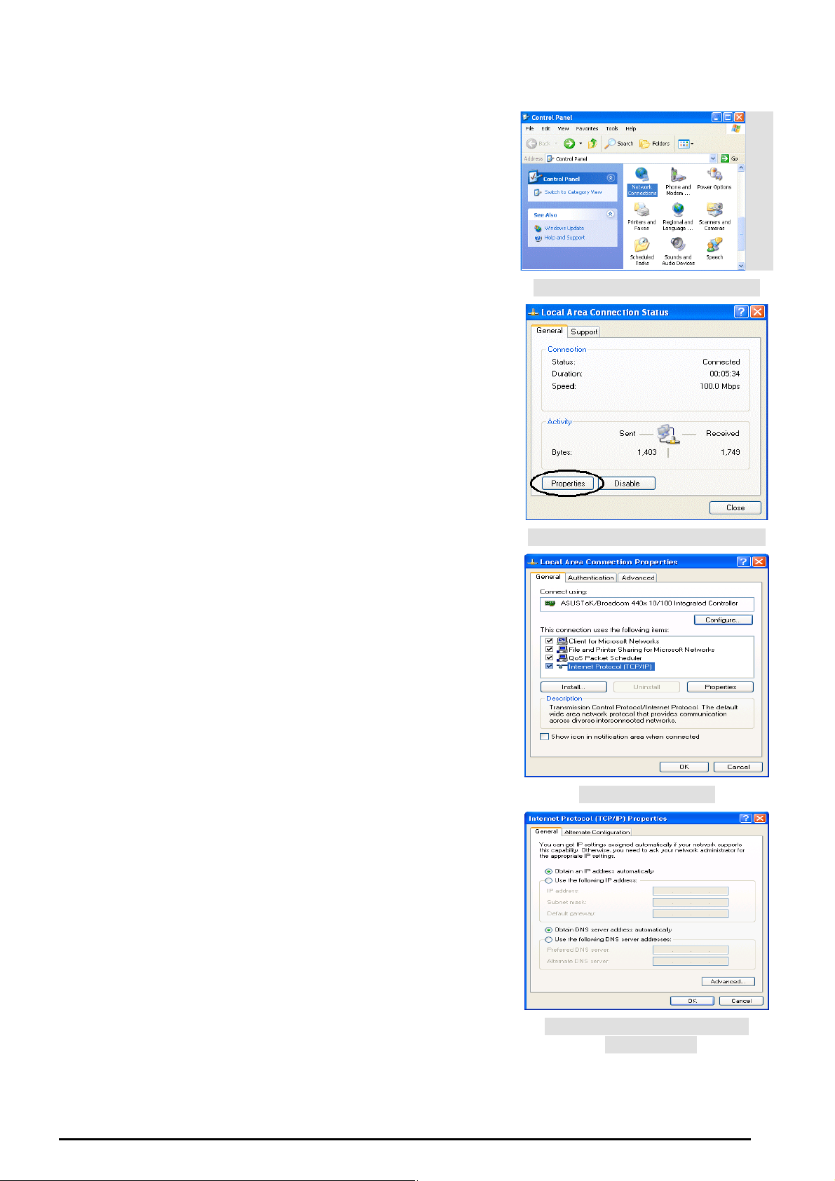
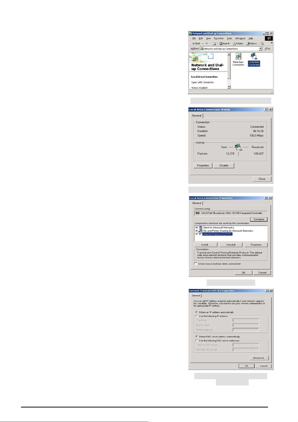
Config uring PCs in Windows in Window XP
1. Go to Start / Contr ol Panel (in Classic Vi ew). In the C ontrol
Panel, double-click Netw ork Connections.
2. Double-click Local Area Connection. (See Fi g ure 3.1)
3. In the LAN Area Connection Status window, click
Properties. (See Figure 3.2)
4. Select Internet Protocol (TCP/IP) and click Properties.
(See Figure 3.3)
5. Select the Obtain an IP address automatically and Obtain
DNS server address automatically radio buttons. (See
Fig ure 3.4)
6. Click OK to finish the configuration.
Figure 3.1: LAN Area C onnection
Figure 3.2: LAN Connection St at us
Figure 3.3: TCP / IP
Chapter 3: Basic Insta lla tion
Figure 3.4: I P Address & DNS
Configuration
12
TW-EA510 version 4 ADSL2+, WLAN 802.11g, VPN, Firewall Router
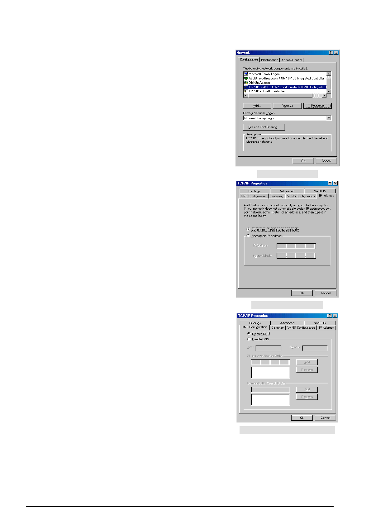
Configuring PCs in Windows 2000
1. Go to Start / Se ttings / Control Pan el. In the Control Panel,
double-click Network and Dial-up Connections.
2. Double-click Local Area (“LAN”) Connection. (See Figure
3.5)
3. In the LAN Area Connection Status window, click
Properties. (See Figure 3.6)
4. Select Internet Protocol (TCP/IP) and click Properties.
(See Figure 3.7)
5. Sel ect t he Obt ain an IP address a utomatically and Obtain
DNS server address automatically radio buttons. (See
Fig ure 3.8)
6. Click OK to finish the c onf igurati on.
Figure 3.5: LAN Area C onnection
Figure 3.6: LAN Connection St at us
Figure 3.7: TCP / IP
Chapter 3: Basic Insta lla tion
Figure 3.8: I P Address & DNS
Configuration
13
TW-EA510 version 4 ADSL2+, WLAN 802.11g, VPN, Firewall Router
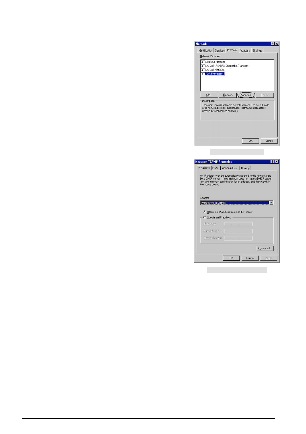
Configuring PC in Windows 95/98/ME
1. Go to Star t / Settin gs / Control Pa nel. In the Control Panel,
double-click Network and c hoose the Configuration tab.
2. Select TCP / IP - > NE2000 Co mpatible, or the na me of any
Network Int erface Ca rd (NIC) in your PC. (See Figure 3.9)
3. Click Properties.
4. Select the IP Address tab. I n this page, click t he Obtain an
IP address automat ic ally radio but t on. (S ee Fi gur e 3.10)
5. Then select t he DNS Configuration tab. (See Figure 3. 11)
6. Select the Disable DNS radio button and click OK to finish
the configuration.
Figure 3.9: TCP / IP
Figure 3.1 0: I P Address
Chapter 3: Basic Insta lla tion
Figure 3.1 1: D N S Configurat ion
14
TW-EA510 version 4 ADSL2+, WLAN 802.11g, VPN, Firewall Router
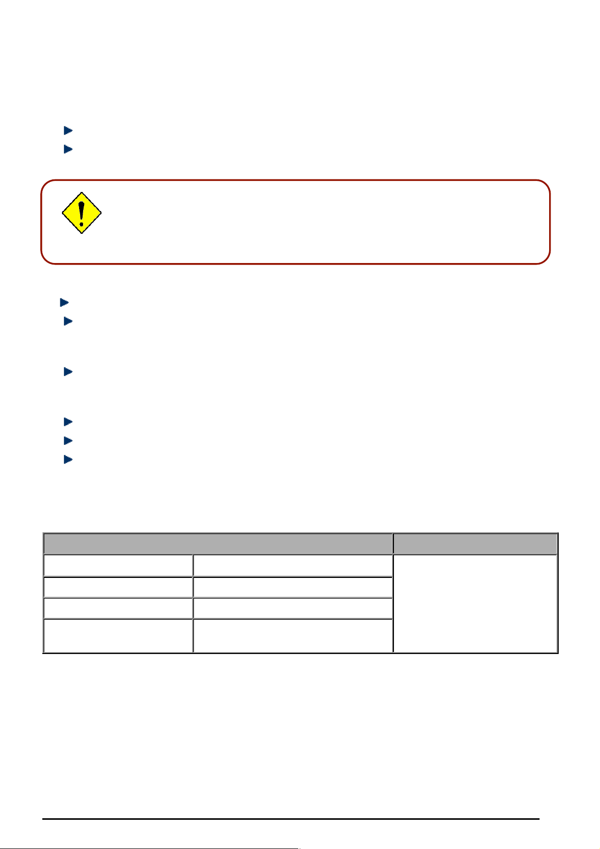
Configuring PC in Windows NT4.0
1. Go to Start / Settings / Control Panel. In the Control
Panel, double-click Netw ork and choose the Protocols tab.
2. Select TCP/IP Protocol and click Properties. (See Figure
3.12)
3. Sel ec t t he O btai n an IP addr ess fro m a DHCP server radio
button and click OK. (See Figure 3.13)
Figure 3.12: TCP / IP
Figure 3.1 3: I P Address
Chapter 3: Basic Insta lla tion
15
TW-EA510 version 4 ADSL2+, WLAN 802.11g, VPN, Firewall Router
Factory Default Settings
Before co nf iguring yo ur, y ou need to know the foll owing default s et t ings.
Web Interface (Username and Password)
Username: admin
Pas sword: a dmin
The defau lt us ername a nd passwor d are “admin” and “admin” respectively.
Attention
Attention
If you ever f orget the u sername/ p assword t o login to the router, you may
press the RESET b ut ton up to 6 se conds to re store the fac tory default
settings.
Caution: After pressing the R ESET button for more than 6 s econds, to be sure you power
cycle the device again.
LAN Device IP Settings
IP Address: 192. 168.0.254
Subnet M as k : 255.255.255.0
ISP setting in WAN site
R FC-14 83 Bri dged IP LL C
DHCP server
DHCP server is enabled.
St art I P Address: 192.168.0. 100
IP pool counts: 100
LAN and WAN Port Addresses
The param et ers of LAN and WAN port s are pre-se t in t he f ac t ory . T he default v alues are shown bel ow.
LAN Port WAN Port
IP addres s 192.168.0.254
Subnet Mask 255.255.255.0
DHCP server function Enabled
IP addres ses for
distribution to PCs
100 IP addres ses continuing fr om
192.168. 0. 100 throu gh 192.16 8. 0. 199
The RFC-14 83 Bridged IP LL C
function is enabled to
automatically get the WAN IP
address from the ISP.
Chapter 3: Basic Insta lla tion
16

TW-EA510 version 4 ADSL2+, WLAN 802.11g, VPN, Firewall Router
Information from your ISP
Before co nfiguring this devic e, you have to chec k with your ISP (Inter net Service Provid er) to find out
what kind of serv ice is prov ided suc h as DHCP (Obtain an IP Address Automatically, Static IP (Fixed IP
Address) an d PPPoE.
Gather th e inf ormation as illustrate d in t he follo win g t able and kee p it f or ref erence.
VPI/VCI, V C / LLC-based multiplexing, Username , Password, Se rvice Nam e,
PPPoE
PPPoE / PPPoE
with Pass-through
PPPoA
and Domai n Na me Syst e m (DNS) IP a ddr ess (it ca be autom atica lly as sig ned
by your ISP when you c onnect or be s et manually).
VPI/VCI, V C / LLC-based multiplexing, Username , Password, Se rvice Nam e,
and Domai n Na me Syst e m (DNS) IP a ddr ess (it ca be autom atica lly as sig ned
by your ISP when you connect or be set manually). In addition, additional
WAN addr es s c an be assigned using PPPoE dialer.
VPI/VCI, VC / LLC-based multiplexing, Username, Password and Domain
Name Sys te m ( DNS) I P ad dr ess (it c a be a uto ma tic ally ass ign ed by y our I SP
when you connect or be set man ually).
RFC 1483 Bridge d
RFC 1483 Routed
VPI/VCI, VC / LLC-b as ed multiplex ing to use Bridged M ode.
VPI/VCI, VC / LLC-based multiplexing, IP address, Subnet mask, Gateway
address, and Domain Name System (DNS) IP address (it is a fixed IP
address).
Chapter 3: Basic Insta lla tion
17
TW-EA510 version 4 ADSL2+, WLAN 802.11g, VPN, Firewall Router
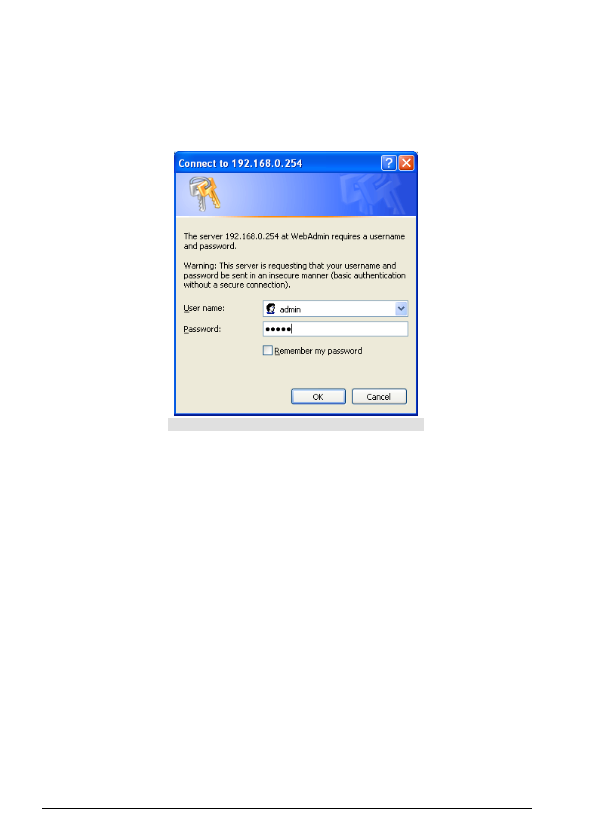
Configuring with your Web Browser
Open your web bro wser, enter t he I P address of your router, which by default is 192.168.0.254, an d click
“Go”, a user na me an d pass word windo w prompt will appear. The default username and password
are “admin” and “admin”. (See Figure 3.14).
Figure 3.1 4: User name & Passwor d Prompt Wi donw
Congratulation! You are now successfully logon to the Router!
Chapter 3: Basic Insta lla tion
18

TW-EA510 version 4 ADSL2+, WLAN 802.11g, VPN, Firewall Router
Chapter 4: Configuration
At the conf iguratio n homep age, the lef t navigation pane w here bookmarks are prov ided links y ou direc t ly
to the desired setup page, including:
Status
- ARP Table
- Wireless As s oc iation
- Routing Ta ble
- DHCP Table
- PPTP Status
- Email Status
- Event Log
- Error Log
- NAT Sessions
- Diagnostic
- UPnP Po rtmap
Quick Start
Configuration
- LAN
- WAN
- System
- Firewall
- VPN
- QoS
- Virtual S erv er
- Time Sc hedule
- Advanced
Save Confi g to FLASH
Language (provides use r int erface in Fi nnish and English lan guages)
Logout
Chapter 4:Configuration
19

TW-EA510 version 4 ADSL2+, WLAN 802.11g, VPN, Firewall Router
Status
ARP Table
This section d isplays the ro uter’s ARP (Add ress Resolutio n Protocol) Tabl e, which shows t he mapping
of Internet (IP) a ddr esses to Ethe rn et (MA C) addr ess es. Th is is us eful as a quick way of deter mini ng t he
MAC addr ess of the network i nterface of your P Cs to us e with the router’s Firewall – MAC Address
Filter function. See the Firewall s ec t ion of this m anual for mo re informat ion on this fe at ure.
IP Address: A list of IP addres s es of devices o n y our LAN (Local Area N et w ork ).
MAC Addres s: The M AC (Media Ac c es s Control) addresses f or each device on your LAN.
Interface: The int erf ac e name (o n t he router) that this IP Ad dres s c onnects t o.
Static: St at ic s t at us of t he ARP table entry:
“no” for dynamically-gen erated A RP table entr ies
“yes” for stat ic ARP table entries added by the user
Wireless Association Table
AP Index: you can selec t “ MAIN”,”Virtual AP 1” and “ Virtua l AP2”
IP Address: It is IP address of wir eless client t hat joins this network.
MAC: The MAC a ddress of wireless clie nt .
Chapter 4:Configuration
20
TW-EA510 version 4 ADSL2+, WLAN 802.11g, VPN, Firewall Router
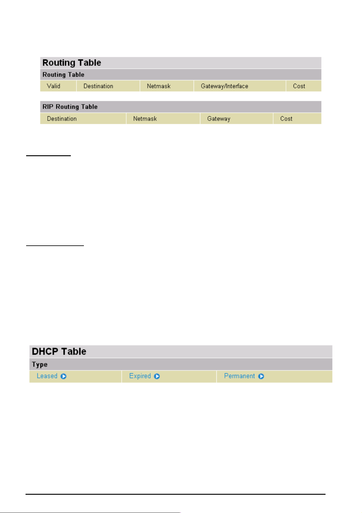
Routing Tab le
Routing Ta ble
Valid: It indic at es a success f ul routing st at us .
Destination: The IP address of the destinat ion net wo rk .
Netmask: Th e destinat ion net mask addres s.
Gateway/Interface: The IP a ddress of the gateway or existing interfac e t hat this route will use.
Cost: The number of hops count ed as the cost of the route.
RIP Ro uting Ta ble
Destination: The IP address of the destinat ion net wo rk .
Netmask: Th e destinat ion net mask addres s.
Gateway: The IP ad dres s of t he gate way t hat this route will use.
Cost: The number of hops count ed as the cost of the route.
DHCP Table
Leased: The DH CP assig ned IP addr esses infor matio n.
IP Address: A list of IP addres s es of devices o n y our LAN (Local Area N et w ork ).
Expired: The expired IP addresses informat ion.
Permanent: The f ix ed host ma pping infor m at ion
Chapter 4:Configuration
21
TW-EA510 version 4 ADSL2+, WLAN 802.11g, VPN, Firewall Router
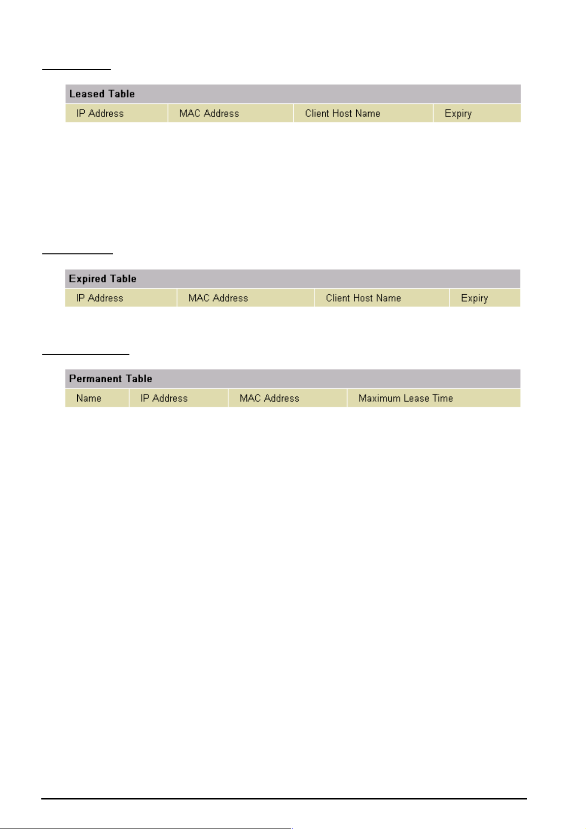
Leas e d Ta bl e
IP Address: The IP address t hat assig ned t o c lient.
MAC Addres s: The MAC address of client.
Client Host Name : The H os t N ame (Com put er Name) of c lient .
Expiry: The curre nt lease time of c lient.
Expi re d Ta ble
Please ref er t he Leased Table.
Per ma n e nt Ta ble
Name: The name you assigned to the Permane nt c onf iguration.
IP Address: The fixed IP address for the s pecify client .
MAC Addres s: The MAC Address that y ou want t o as s ign the fixe d I P address
Maxim um Lease Tim e: The maxim um lease ti m e int erval you allow to clie nt s
Chapter 4:Configuration
22
TW-EA510 version 4 ADSL2+, WLAN 802.11g, VPN, Firewall Router
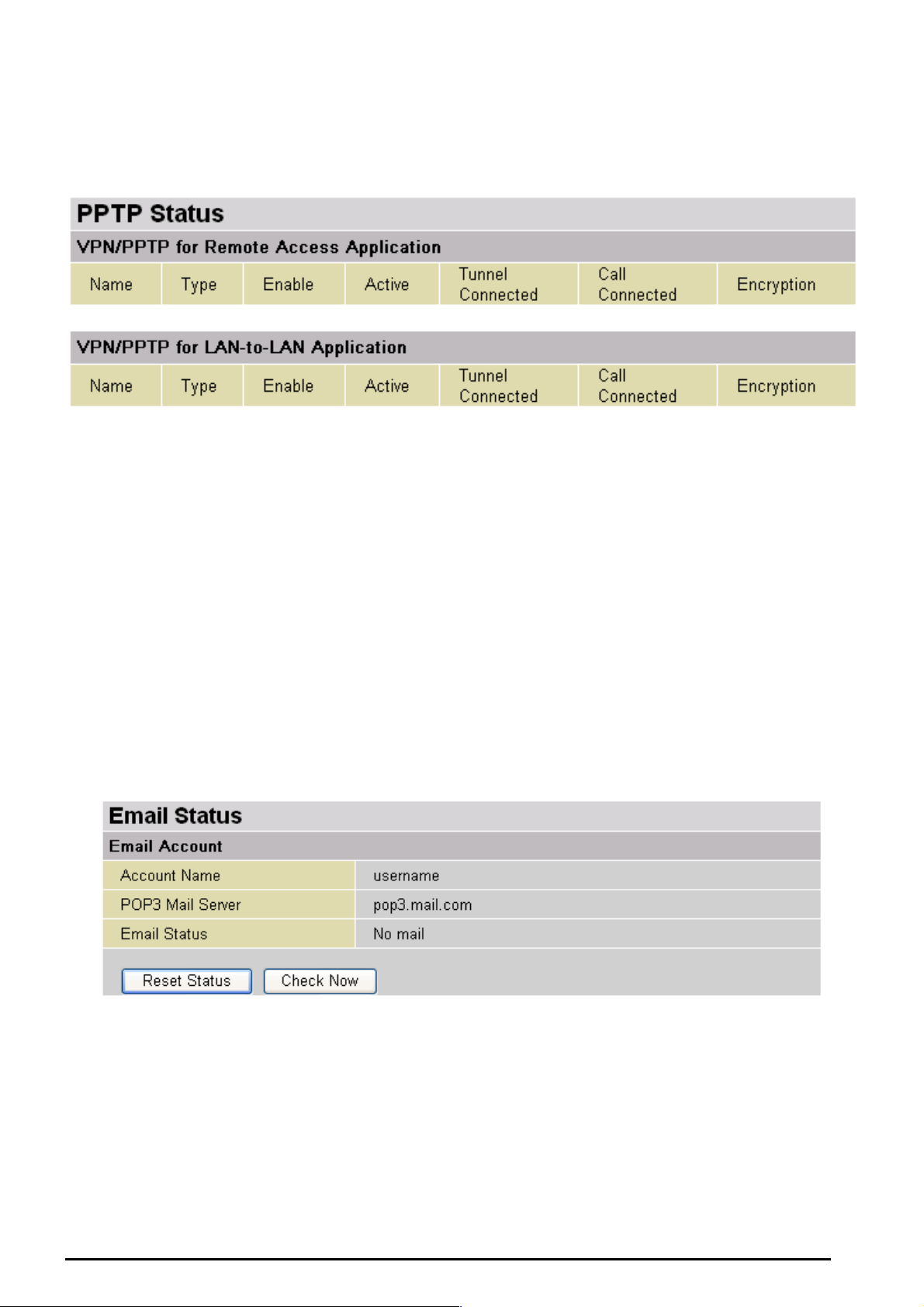
PPTP Status
This shows details of y our c onfigure d PPTP VP N C onnections .
Name: The name you assigned to the part icular P PTP connec t ion in your V PN configu rat ion.
Type: The type of c onnection (dial-in/di al-out).
Enable: Whether the connection is c urrently enabled.
Active: Whether t he c onnection is current ly ac t iv e.
Tunnel Connected: Whether the VPN Tunnel is currently con nec ted.
Call Connected: If the Call for this VPN entry is c urrently con nec ted.
Encryption: The encryption t y pe used for t his VPN connection.
Email Sta tus
Details and s t at us f or t he Email Ac c ount you hav e configured the router to check. Please see t he
Advanced section of this manual for details on t his function.
Chapter 4:Configuration
23
TW-EA510 version 4 ADSL2+, WLAN 802.11g, VPN, Firewall Router
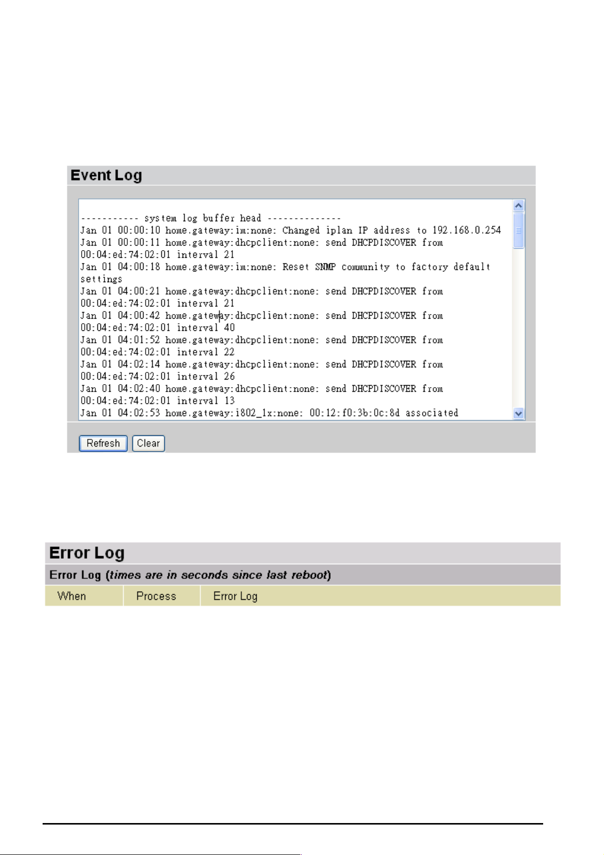
Event Log
This pag e displays the rout er’s Event Log entri es . M ajor events are logged to this window, such as when
the router’s ADSL connection is disconnected, as well as Firewall events when you have enabled
Intrusion or Blocking Lo gging in the Configuration – Firewall sect ion of the interfac e. Please s ee the
Firewall sectio n of t his manual for more details on how to enable Fir ewall loggi ng.
Error Log
Any errors enc ountere d by t he router (e.g. invalid names giv en to entries ) are logged to this window.
Chapter 4:Configuration
24
TW-EA510 version 4 ADSL2+, WLAN 802.11g, VPN, Firewall Router
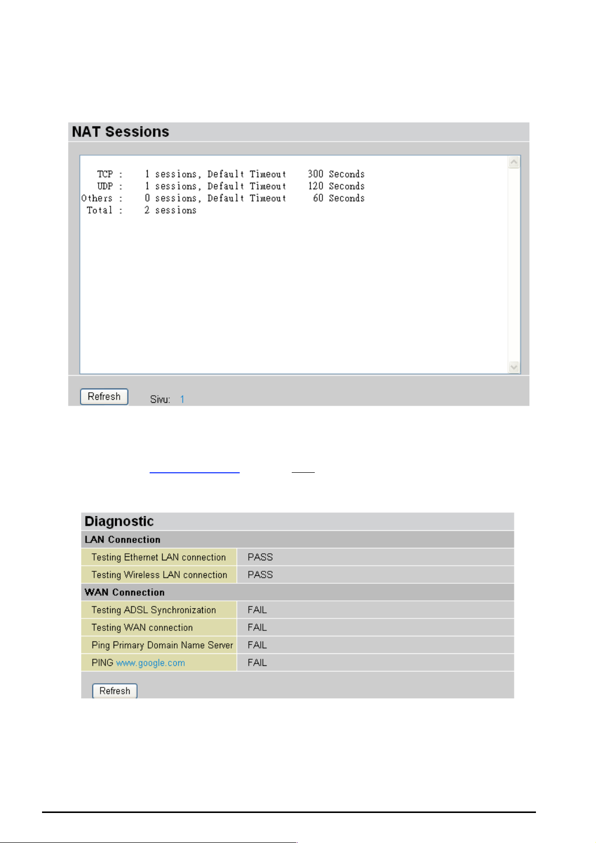
NAT Sessions
This section lists all current NAT sessions between int erface of ty pes ex ternal ( W AN) and internal (LAN).
Diagnostic
It tests the connection to computer(s) which is connected to LAN ports and also the WAN Internet
connection. If PING www.google.com
PC’s DNS settings is set correctly.
is shown FAIL and th e rest is PASS, y ou ought to ch eck your
Chapter 4:Configuration
25

TW-EA510 version 4 ADSL2+, WLAN 802.11g, VPN, Firewall Router
UPnP Portmap
The section lists all port-mapping established using UPnP (Universal Plug and Play). Please see the
Advanced section of this manual for more details on UPnP and the r out er’s UPnP c onfiguration opti ons .
Chapter 4:Configuration
26

Quick Start
TW-EA510 version 4 ADSL2+, WLAN 802.11g, VPN, Firewall Router
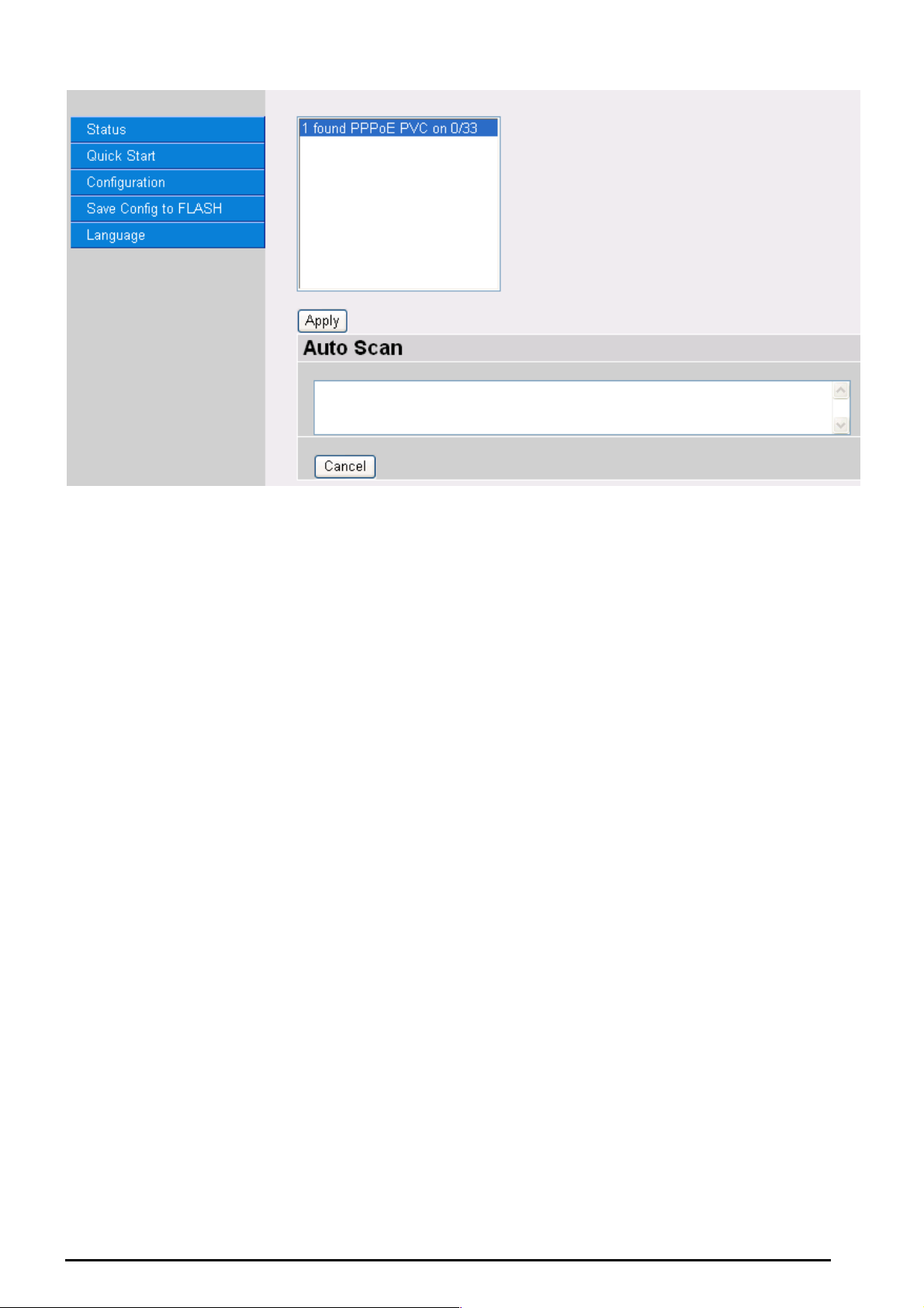
For detail ed ins t ructions on c onfiguri ng y our WA N set t ings , please see t he WAN section of this ma nual.
Your ISP will be able to supply all the details you need, alternatively, if you have deleted th e current
WAN Con nect ion i n the WAN – ISP sect ion of th e inte rface, y ou c an us e th e rout er’s PV C Sc an f eat ure
to attempt t o determine t he Encapsulation ty pes off ered by your I SP.
Click Start to begin scannin g for encapsul ation types of fered by you r ISP. If the sc an is successf ul you
will then be p resented with a list of supporte d opt ions:
Chapter 4:Configuration
27
TW-EA510 version 4 ADSL2+, WLAN 802.11g, VPN, Firewall Router
Select the desired o ption fro m the list an d click Apply to ret urn to the Quick Sta rt interfac e to conti nue
configuri ng yo ur IS P con nectio n. Pl eas e note t hat the cont ent s of t his list will vary , de pendi ng on wh at is
supporte d by y our ISP.
Chapter 4:Configuration
28
TW-EA510 version 4 ADSL2+, WLAN 802.11g, VPN, Firewall Router
Configuration
When you clic k t his it em, you g et f ollowing sub-items to configure t he ADSL r out er.
LAN, WAN, System, Firewall, VPN, QoS, Virtual Server, Time Schedule and Advanced
These func t ions are desc ribed below in the fol lowing sections.
LAN (Local Area Network)
There are s even items withi n the LAN sectio n: Bridge Interface, Ethernet, IP Alias, Ethernet Client
Filter, Wirele ss, Wir ele ss Securi ty, Wireles s Clien t Filter, Port Setti ng and D HCP Ser ver.
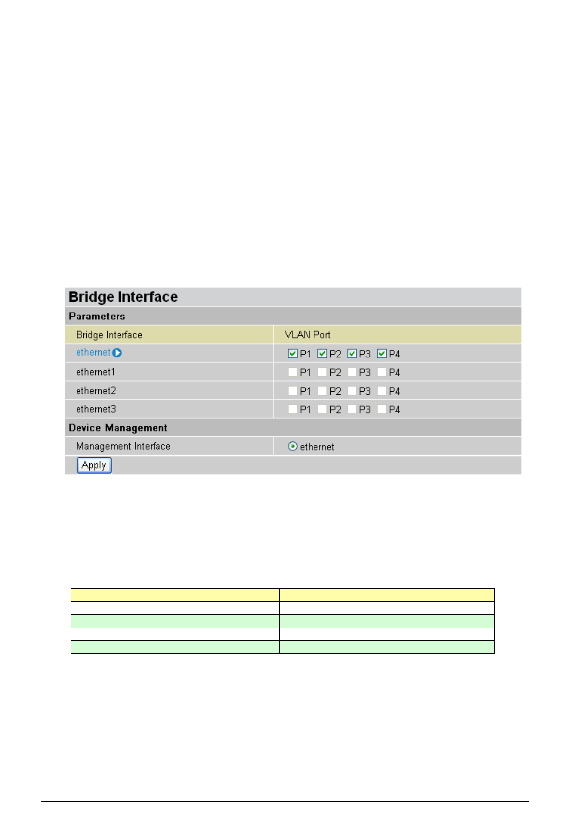
Bridge Interface
You can setup member ports f or each VLA N g roup under Bridge Int erf ace section. From the example,
two VLA N gr oups need to be created.
Ethernet: P1 (Port 1)
Ethernet1: P2, P3 a nd P4 (Port 2, 3, 4) Please u ncheck P2, P3, and P4 f rom Ethernet VLAN po rt f irs t .
Note: You should setup each VLAN group with caution. Each Bridge Interface is arranged in this order.
Bridge Interface VLAN Port (Always starts with)
Ethernet P1 / P2 / P3 / P4
Ethernet1 P2 / P3 / P4
Ethernet2 P3 / P4
Ethernet3 P4
Management Interface: To specify which VLAN group has possibility to do device management, like
doing web mana gem ent.
Note: NAT/NAPT can be applied to management interface only.
Chapter 4:Configuration
29

TW-EA510 version 4 ADSL2+, WLAN 802.11g, VPN, Firewall Router
Ethernet
Primary I P Address
IP Address: The default IP on t his router.
Subnet Mask: The default subn et m as k on this router.
RIP: RIP v1, RI P v 2, and RIP v2 M ult ic as t . Ch ec k to enable RIP funct ion.
IP Alias
This functi on supports t o create multiple virtual IP int erfaces on this router. It helps t o connect two o r
more local networks t o t he I SP or remote node. In t his c as e, an internal r out er is not required.
IP Address: Specify an IP address on t his v irt ual interface.
SubNetmask: Specify a su bn et mask on this v irtual interface.
Security I n ter face: Spec if y t he f irewall set t ing on this v irt ual interfac e.
Internal: The net work is behind NAT. Al l traffic will do network addres s trans lation when s endin g out to
Internet if NA T is enabled.
External: T here is no NAT on this IP interface a nd connected t o the Internet direc tly. Mostly, it will be
used wh en pr ovidi ng multi ple publ ic I P ad dress es by IS P. In t his case, y ou c an us e p ublic IP addre ss in
local net wo rk w hic h gateway I P address point to the IP address on t his interf ac e.
DMZ: Specify this network to DMZ area. There is no NAT on this interfac e.
Chapter 4:Configuration
30

TW-EA510 version 4 ADSL2+, WLAN 802.11g, VPN, Firewall Router
Ethernet Client Filter
The Ether net Client Filt er supports up to 16 Ether net network machines that helps yo u to manag e your
network c ontrol to acce pt traffic f rom specific authorized machines or can restric t unwant ed machine(s )
to access y our LAN.
There are no pre-define Ethernet MAC address filter rules; you can add the filter rules to meet your
requirements.
Ethernet Client Filter: Default set t ing is set to Disable.
Allowed: check to authorize spec if ic device ac c es s ing your LA N by insert th e M AC Address in t he
space provide d or click
Blocked: c heck to preve nt unwanted device acc essing your L AN by insert t he MAC Addres s in
the space provided o r c lic k
The maximum client is 16. The MAC addresses are 6 bytes long; they are presented only in
hexadeci m al c haracters . T he number 0 - 9 and letters a - f are accept able.
Note: Follow the MAC Address Format xx:xx:xx:xx:xx:xx. Semicolon ( : ) must be included)
Candidates: automatical ly det ec t s devices connec t ed t o t he router through the Ethernet. .
. Make sure your PC’s MAC is listed.
. Make sure your PC’s MAC is not listed.
Active PC in LAN
Chapter 4:Configuration
31
TW-EA510 version 4 ADSL2+, WLAN 802.11g, VPN, Firewall Router
Active PC in LAN displays a list of individual Ethernet device’s IP Address & MAC Address which
connecting to the rout er.
You can eas ily by c hecki ng the b ox nex t to t he IP add ress t o be bloc ke d or allo wed. The n, Add to insert
to the Ethernet Client Fi lt er t able. The m ax imum Ethe rnet client is 16.
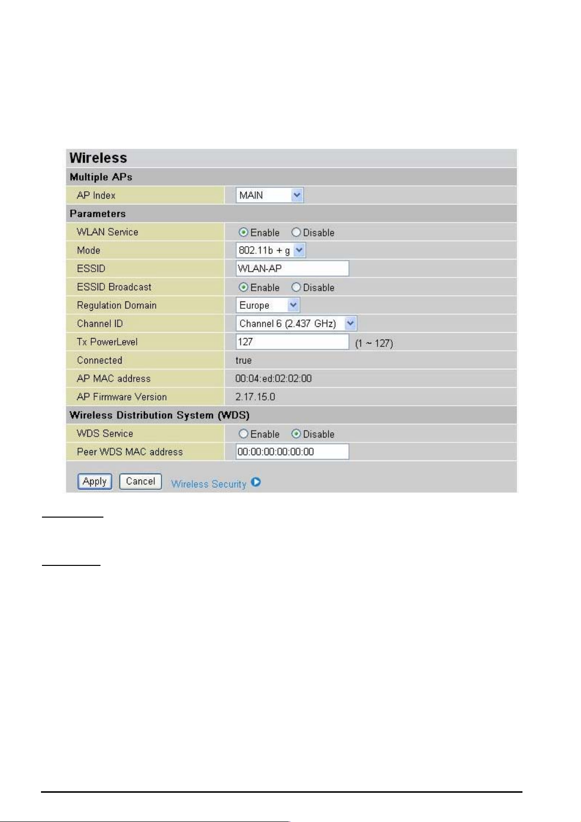
Wireles s
Mutiple APs
AP Index: you can selec t “ Main”, “ Virt ual AP1” and “Virtu al AP2”
Parameters
WLAN Service: Default s etting is set to Enable. If you d o not have any wireless, both 802.11g and
802.11b, dev ice in your network, s elect Disable.
Mode: The default sett ing is 802.11b+g (Mixed mod e). If you do not know or hav e both 11g and 11b
devices in y our net work, then k eep the default in mixed mode. From the dro p-down manual, yo u can
select 802.11g if y ou have only 11g card. I f y ou hav e only 11b card, then s elec t 802.11b.
ESSID: T he ESSI D is t he unique name of a wirele s s ac c es s point (AP) to be distinguishe d f rom another.
For securit y propose, c hange the d ef ault wlan-ap to a unique I D n ame to the AP w hich is already built-in
to the router’s wirel ess int erfac e. I t is case s ensitiv e and must not exc ess 3 2 char act ers. M ake sur e your
wireless c lient s have exac t ly t he ESSID as t he device, in order to get c onnected t o y our network .
Note: It is case sensitive and must not excess 32 characters.
ESSID Broadcast: It is function in which transmits its ESSID to the air so that when wireless client
searches f or a network , rout er can then be discovered an d recognized. Defa ult s et t ing is Enable.
Chapter 4:Configuration
32

TW-EA510 version 4 ADSL2+, WLAN 802.11g, VPN, Firewall Router
Disable: If you do not want broa dcast y our ESSI D. Any client uses “any” wireless set ting cann ot
discover t he Ac cess Po int (AP) of your router.
Enable: Any client t hat us ing the “any” setting can discov er t he Access Point (A P) in
Regulation Domain: There are seven Regulation Domains for you to choose from, including North
America ( N.America), Europe, Fr ance, etc. Th e C hannel ID wil l be different based on this s et t ing.
Channel ID: Select the wireless connection ID channel that you would like to use. Use the Scan
Channel Usag e to help to selec t non-occupied wir eles s c hannel.
Scan Channel Usage: Wireless channel scan takes up to 14 seconds to survey the channel ID
in the net work area. The result will show all ID channel is b eing occupied or not occ upied.
Note: Wireless performance may degrade if select ID channel is already being occupied by other AP(s).
TX PowerL evel: It is function th at en ha nces t he wi reles s trans m itting s igna l st rengt h. Us er m ay a djust
this power level from mi nimum 0 up t o maximu m 2 55.
Note: The Power Lev el maybe di fferent in each acces s network us er pre mises env ironment and choos e the most
suitable level for your network.
Connected: R epres ent ing in true or false. That it is the connection status between the system and the
build-in wireles s card.
AP MAC Address: It is a unique ha rdware ad dress of the Ac c es s Point.
AP Firmware Version: The Access Poi nt f irmware v ers ion.
Wireless Distribution System (WDS)
It is a wireless acces s poi nt mod e that ena bles wireles s li nk an d co mmunic at ion wit h othe r acc ess poi nt.
It is easy t o be installed simply define peer’s MAC address of the c onnected AP. WD S t akes adv antages
of cost saving and flexibility which no extra wireless client device is required to bridge between two
access points and extending an existing wired or wireless infrastructure network to create a larger
network. I t c an c onnect up to 1 wir eless APs for extending cover range at the same ti m e.
In additio n, WD S enhanc es its link conn ectio n securit y in WE P mode, WE P key enc ryption must b e the
same for bot h ac cess poi nt s .
WDS Servi ce: The default setting is Disabled. Check Enable radio button t o ac tivate t his f unc t ion.
1. Peer WDS MAC A ddress: It is the associated AP’s MAC Address. It is important that your peer’s AP
must inclu de y our MA C ad dress in order to ackn owledge a nd commu nic ate with e ac h ot her.
Note: For MAC Address, Semicolon ( : ) must be included.
Chapter 4:Configuration
33
TW-EA510 version 4 ADSL2+, WLAN 802.11g, VPN, Firewall Router
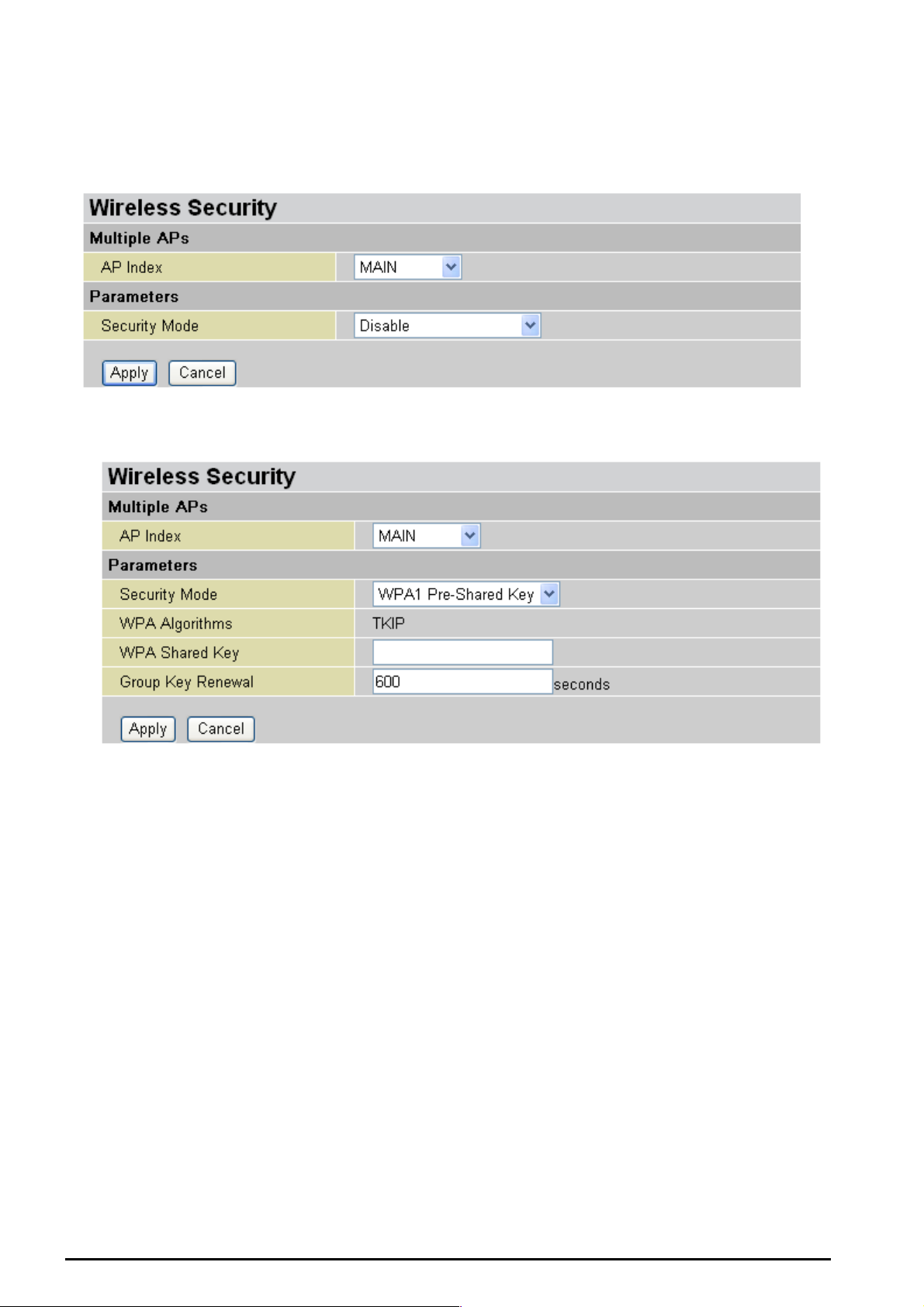
Wireles s Security
You can disable or enable with WPA or WEP for protecting wireless network. The default mode of
wireless s ec urit y is disabled.
WPA-PS K ( T KIP) / WPA- PSK (AES) Pre-S hared Key
WPA Algorithms: There are two types of the WPA-PSK, WPA1 and WPA2. The WPA1 adapts the
TKIP (Temp oral Key Integrit y Prot ocol) encry pte d algorit hms whic h incor porat es Mes sa ge Integrit y Cod e
(MIC) to provid e protecti on against hackers . The WPA 2 adapts C CMP (Cip her Block Ch aining M essage
Authentic ation C ode Prot oco l) of the AES (Adva nc ed Encrypt i on Secu rity) algor ith ms.
WPA Shared Key: The key for network authentication. The input format is in character style and key
size should be in the ra nge between 8 and 63 c haracters.
Group Key Renewal: The period of renewal ti me for c hanging t he security k ey auto matically between
wireless c lient and Acces s Point (AP). Default value is 3600 s econds.
Idle Timeout: The default idle tim eout is 3600 s econ ds. A Timeo ut valu e base on the c ase of no data
traffic is s end or rec eived. If Router detects no traff ic in t he wireless , it will sta rt t iming the c loc k and drop
the session as it reaches to the defined ti meout value. New ses sion will be re-estab lished after th e old
session.
Chapter 4:Configuration
34
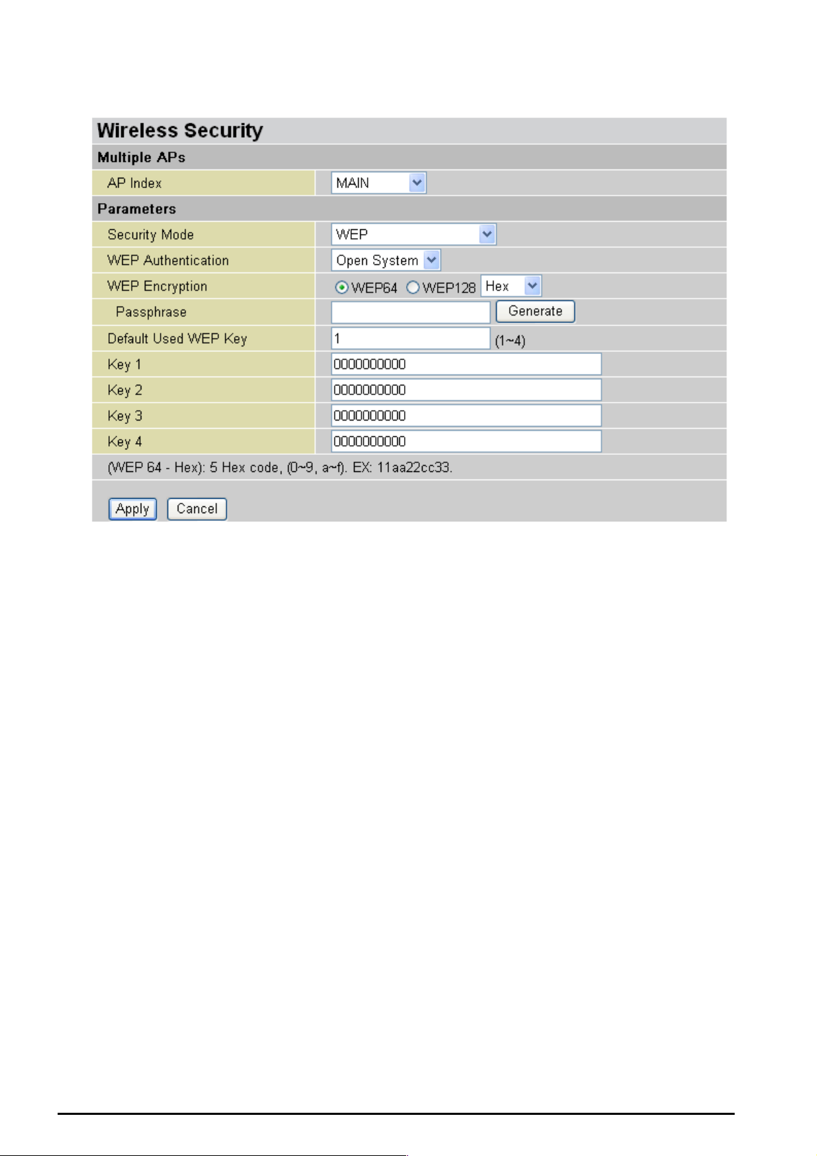
WEP
TW-EA510 version 4 ADSL2+, WLAN 802.11g, VPN, Firewall Router
WEP Encryption: To prev ent unauthoriz ed wireless s tations from access ing data trans mitted over the
network, the route r offers highly s ecur e data encrypt ion, kno wn as WEP. If y ou requ ire hi gh securit y for
transmissions, there are two alternatives to select from: WEP 64 and WEP 128. WEP 128 will offer
increase d s ec urity over W EP 64.
Passphrase: This is us ed to gene rate WEP k eys auto matically based upon t he input string and a predefined algorithm in WEP64 o r WEP128.
Default Use d WEP Key: Sel ec t t he encrypti on k ey ID; pleas e refer to Ke y (1~4) below.
Key (1-4): Enter the key to encrypt wireless data. To allow encrypted data transmission, the WEP
Encryptio n Key val ues on all wireless st ations m ust be the sa me as the router. There are fo ur keys f or
your selection. The input format is in HEX style, 5 and 13 HEX codes are required for WEP64 and
WEP128 respectively.
Chapter 4:Configuration
35

TW-EA510 version 4 ADSL2+, WLAN 802.11g, VPN, Firewall Router
Wireless Client Filter
The MAC Ad dr ess s upport s u p to 16 wirel ess n etw ork machin es an d h elps yo u to mana ge yo ur n et work
control to ac cept traff ic from specific authorize d machi nes or to restric t unwant ed machine (s) to acc ess
your LAN.
There are no pre-def ine MAC Address filter rules; y ou c an add the filt er rules to m eet y our requirements .
Filter Action: Default setting is s et t o Disable.
Allowed: c hec k t o authorize specific device accessing your LA N by insert the M AC Address in the
space provide d or click
Blocked: c heck to p rev ent un wa nt ed device accessing the LA N by insert th e MAC Address in t he
space provide d or click
The maximum client is 16. The MAC addresses are 6 bytes long; they are presented only in
hexadeci m al c haracters . T he number 0 - 9 and letters a - f are accept able.
The maximum client is 16. The MAC addresses are 6 bytes long; they are presented only in
hexadeci m al c haracters . T he number 0 - 9 and letters a - f are accept able.
Note: Follow the MAC Address Format xx:xx:xx:xx:xx:xx. Semicolon ( : ) must be included.
Candidates: it automatically detects dev ices con nec t ed to the rout er t hrough t he Ethernet. .
Associated Wireless Clients
. Make sure your PC’s M AC is listed.
. Make sur e y our PC’s MA C is not listed.
Chapter 4:Configuration
36

TW-EA510 version 4 ADSL2+, WLAN 802.11g, VPN, Firewall Router
Associate Wireless Client displays a list of individual wireless device’s MAC Address that currently
connects t o t he router.
You can e asily by check ing the box next to the MAC address t o be blocked or allowed. Then, Add to
insert to the W ireless Cli ent (MAC Address) Filter table. Th e m ax imum Eth ernet client is 16.
Port Setting
This section allows you to configure the settings for the router’s Ethernet ports to solve some of the
compatibil ity pro blems t hat may be enc ounte red w hile con necting t o the Int ernet , as wel l allowi ng users
to tweak the perfor ma nc e of t heir network .
Port # Connection Type: There are Six opt ions to choose f rom: Auto, dis able, 10M half -duplex, 10 M
full-duplex , 100M ha lf -duplex, 100M full-duplex an d Disable. Sometim es , t here are Et hernet compatibilit y
problems with legacy Ethernet devices, and you can configure different types to solve compatibility
issues. The def ault is Auto, which users should keep unless the re are specific problems with PCs not
being able to access y our LAN.
nd
IPv4 TOS priority Control ( Advanced users): TOS, Type of Se rvices, is the 2
octet of an I P pac ket.
Bits 6-7 of t his oc t et are reserved and bit 0- 5 are used to s pecify the priority of the packet.
This featur e us es bits 0-5 to cl ass ify t he pack et’s priorit y. I f the pac ket is high pri ority , it wil l flo w first and
will not be co nstrai ned by th e Rat e Limit. Therefore, when t his featu re is en abled, t he rout er’s Eth ernet
switch will check the 2
nd
octet of each IP packet. If the value in the TOS field matches the checked
values in the t able (0 to 6 3), t his pac ket will be treated as high priorit y .
Chapter 4:Configuration
37

TW-EA510 version 4 ADSL2+, WLAN 802.11g, VPN, Firewall Router
DHCP Server
You can disable or enable the DHCP (Dynamic Host Configuration Protocol) server or enable the
router’s DHCP relay functions. The DHCP protocol allows your router to dynamically assign IP
address es t o PCs on your network if t hey are configured to obtain IP addr es s es automat ic ally .
To disable the router’s DHCP Server, check Disabled and clic k N ext, then click Apply. When the DHCP
Server is d is abled you w ill need to m anually ass ign a fixed I P address t o each P Cs on your n etwork, and
set the defa ult gateway for each P Cs t o t he I P addres s of t he router (by default this is 192.168.0.254 ).
To configure the router’s DHCP Server, check DHCP Server and click Next. You can then configure
parameters of the DHCP Server including the IP pool (starting IP address and ending IP address to be
allocated t o PCs on you r network), l ease time for each assigne d IP addres s (the period of time the IP
address ass igned will be v alid), DNS IP a ddress and the g atew ay IP add ress. T hese d etails are s ent to
the DHCP cli ent (i.e. your P C) when it re quests an IP addres s from the DH CP serve r. Click Apply to
enable this function. If y ou check “Use Router as a DNS Server”, the ADSL Rout er will perfor m the
domain na me lookup, f ind the IP address f rom the outside net work auto matically and f orward it bac k to
the reques t ing PC in the LAN (your Local Are a N etwork).
If you check DHCP Relay Agent and click Next, then you will have to enter the IP address of the DHCP
server which will assign an IP address back to the DHCP client in the LAN. Use this function only if
advised to do so by yo ur network a dministrator or ISP.
Click Apply to ena ble this funct ion.
Chapter 4:Configuration
38
TW-EA510 version 4 ADSL2+, WLAN 802.11g, VPN, Firewall Router
WAN (Wide Area Network)
WAN refers to your Wide Area Network connection, i.e. your router’s connection to your ISP and the
Internet. Th ere are two it ems within t he WAN section: ISP, DNS and ADSL.
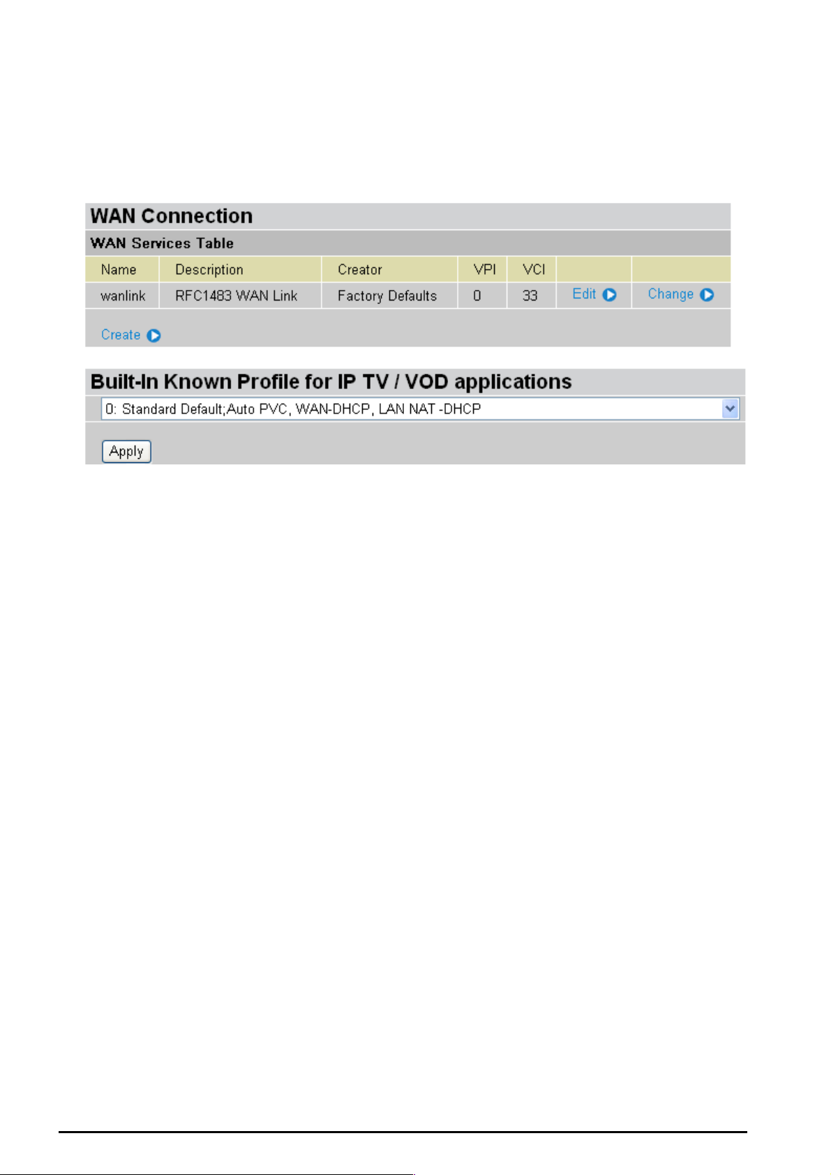
ISP
The factory d efault is PPPoE. I f your IS P uses thi s access protocol, click Edit to input other parameters
as below. If your ISP does not use PPPoE, you can change the default WAN connection entry by
clicking Change.
Some of ISP may provide more service via different WAN connection. In case, you can create more
connections by click ing Create. The devic e c an s upport max imum up t o 8 WAN con nec t ions.
Note: The application of multiple WAN connections is depend on your Service Provider.
A simpler alter nativ e is to selec t Quic k Start from the ma in me nu on t he left . Pleas e see t he Quic k Start
section of the manua l f or more information.
Chapter 4:Configuration
39

RFC 1483 Routed Connections
TW-EA510 version 4 ADSL2+, WLAN 802.11g, VPN, Firewall Router
Description: Yo ur description of this co nnection.
VPI and VCI: Enter the informat ion provid ed by y our ISP.
ATM Class: The Quality of Service for ATM layer.
NAT: The NAT (Network Address Translation) feature allows multiple users to access the Internet
through a single IP account, sharing the single IP address. If users on your LAN have public IP
address es and can acc es s t he I nt ernet direct ly , t he NAT funct ion can be dis abled.
Encapsulation method: Selects the enca psulation format, t he default is LLC Bridged. S elect the one
provided by y our ISP.
IP Assig n ment
Obtain an IP address automatically via DHCP client: specify if the Router can get an IP
address from the ISP (Internet Service Provider) a ut omatically.
Use the follo wing IP Addres s: Specify the I P a ddres s manu ally; t he I P sh ould b e giv en by yo u
our ISP.
RIP: RIP v1, RI P v 2, and RIP v2 M ult ic as t . C hec k to enabl e RIP functio n.
MTU: Maximu m Trans miss ion Unit . The size of th e larges t data gra m (exc ludi ng media -sp ecific headers )
that IP will att empt to send t hrough t he interfac e.
TCP MSS Clam p: This option he lps t o dis cover th e opt imal MT U siz e automat ic ally . Default is enabled.
Chapter 4:Configuration
40

TW-EA510 version 4 ADSL2+, WLAN 802.11g, VPN, Firewall Router
MAC Address Spoofing: This option is r equired by so me service provi ders. You must fill in the MA C
address that s pecify by s erv ice provider when it is required. Default is disa bled.
RFC 1483 Bridged Connections
Description: User-definable name for the connection.
VPI and VCI: Enter the informat ion provid ed by y our ISP.
ATM Class: The Quality of Service for ATM layer.
Encapsulation method: Select the encapsulation f orm at , t his is prov ided by your ISP.
Acceptable Frame Type: Specify what kind of traffic can through this connection, all traffic or only
VLAN tagged.
Filter Type: Specify the ty pe of ethernet filteri ng performed by the named bridge interface.
All Allows all ty pes of ethernet packets t hrough the port.
Ip Allows only I P/ARP types of ethe rnet packets t hrough th e port.
Pppoe Allows only PPPoE t y pes of et hernet p ac k et s t hrough the p ort .
PVID for Untagged Frames: PVID is known as Port VLAN Identifier. When an untagged packet is
received by i nput po rt(s), t his pack et will be ta gged w ith specifi ed PVI D. The v alid valu e range f or PVI D
is 1~4094.
Chapter 4:Configuration
41

PPPoA Routed Connections
TW-EA510 version 4 ADSL2+, WLAN 802.11g, VPN, Firewall Router
Description: User-definable name for the connection.
VPI/VCI: Enter th e infor mation prov ide d by your ISP.
ATM Class: The Quality of Service for ATM layer.
NAT: The NAT (Network Address Translation) feature allows multiple users to access the Internet
through a s ingle I P ac cou nt, s haring a sin gle IP a ddres s. I f users on yo ur LA N hav e pub lic I P addr e sses
and can access the Int ernet direct ly , t he NAT function can be disable d.
Username: Enter the user name provided by your ISP. You can i nput up to 128 alphanumeric charact ers
(case sensitive). This will usually be in the format of “username@ispname” instead of simply
“username”.
Password: Enter t he p ass word provi de d by y ou r I SP. Y ou c an inp ut up t o 128 alphanu meric char act ers
(case sens it iv e).
IP Address: Specify an IP address allowed to logon and access the ro ut er’s web se rv er.
Note: IP 0.0.0.0 indicates all users who are connec ted to this router are allowed to logon the device a nd modify
data.
Authentic ation Protoc ol Typ e: Default is Chap (Aut o). Your ISP will advise y ou whether t o use Chap
or Pap.
Connection:
Chapter 4:Configuration
42

TW-EA510 version 4 ADSL2+, WLAN 802.11g, VPN, Firewall Router
Always on: If you want the router to establish a PPPoA session when starting up and to
automatic ally re-est ablish the PPPoA sess ion whe n dis c onnected by t he ISP.
Connect on Demand: If you want to establish a PPPoA session only when there is a packet
requesti ng access to the Internet (i.e. when a progr am on your computer at tempts to access the
Internet).
Idle Timeout: Auto-disconnect the br oadb an d fire wall g ate way wh en th ere is n o activ ity on t he line f or a
predetermined per iod of time.
Detail: You can define t he destination port an d pac ket type (TCP/UDP) without checkin g by timer.
It allows you t o s et which out going traff ic wil l not t rigger and reset the i dle t imer.
RIP: RIP v1, RI P v 2, and RIP v2 M ult ic as t . C hec k to enabl e RIP functio n.
MTU: Maximu m Trans miss ion Unit . The size of th e larges t data gra m (exc ludi ng media -sp ecific headers )
that IP will att empt to send t hrough t he interfac e.
TCP MSS Clam p: This option he lps t o dis cover th e opt imal MT U siz e automat ic ally . Default is enabled.
Chapter 4:Configuration
43
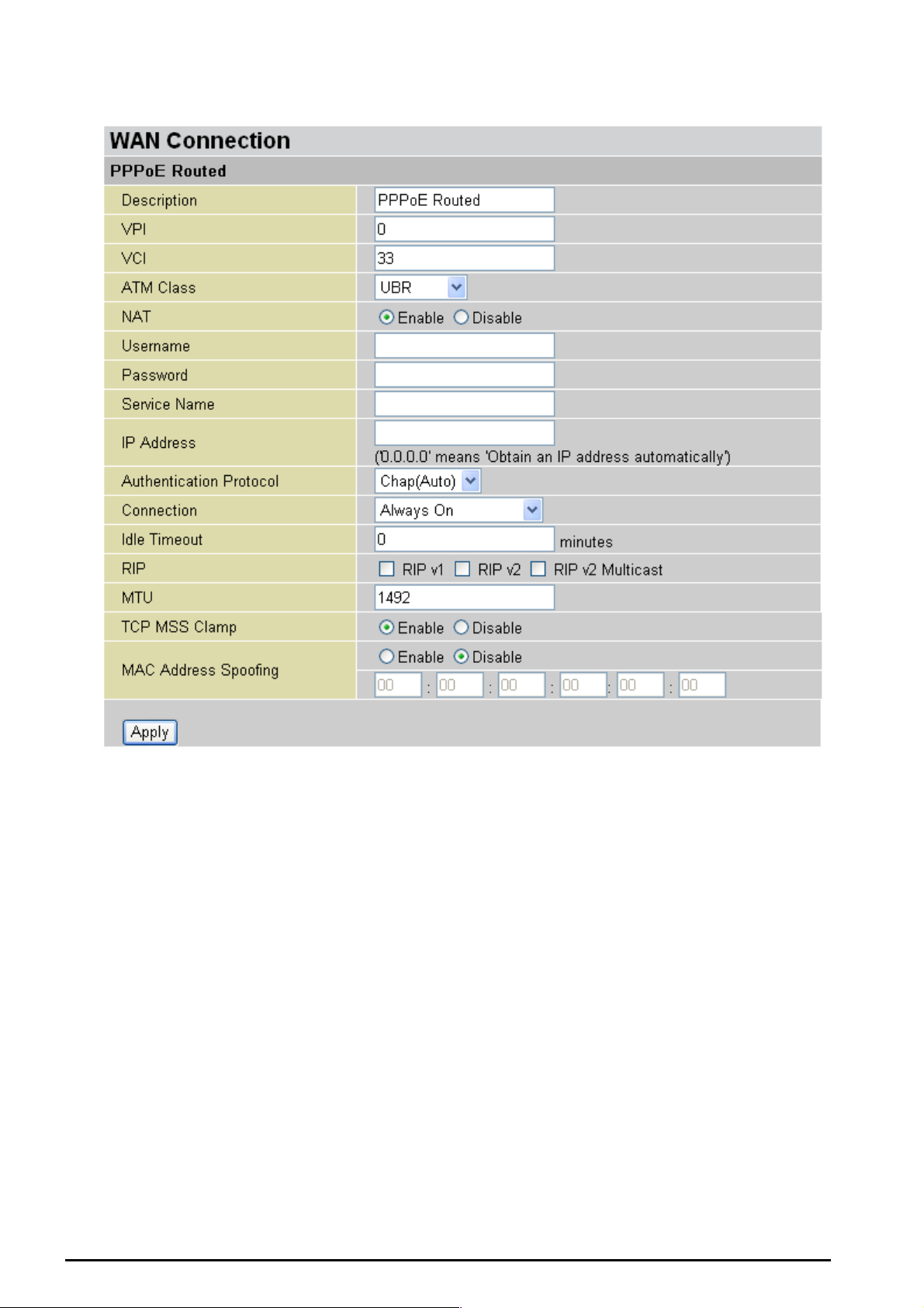
PPPoE Con necti ons
TW-EA510 version 4 ADSL2+, WLAN 802.11g, VPN, Firewall Router
Description: A user-defin able name for t his connection.
VPI/VCI: Enter th e infor mation prov ide d by your ISP.
ATM Class: The Quality of Service for ATM layer.
NAT: The NAT (Network Address Translation) feature allows multiple users to access the Internet
through a single ISP account, sharing a single IP address. If users on your LAN have public IP
address es and can acc es s t he I nt ernet direct ly , t he NAT funct ion can be dis abled.
Username: Enter the user name provided by your ISP. You can i nput up to 128 alphanumeric charact ers
(case sensitive). This will usually be in the format of “username@ispname” instead of simply
“username”.
Password: Enter t he p ass word provi de d by y ou r I SP. Y ou c an inp ut up t o 128 alphanu meric char act ers
(case sens it iv e).
Service Name: This item is for identification purposes. If it is required, y our ISP will provide you the
information. Maxi m um input is 20 alp hanu meric charact ers .
IP Address: specify if the Router can get an IP address from the Internet Server Provider (ISP)
automatically or not. Please click Obtain an IP address automatically via DHCP client to enable the
DHCP client function or click Specify an IP ad dres s to disable the DHCP client functi on, and s pecify the
IP address manually. The setting of this item is specif ied by your I SP.
Chapter 4:Configuration
44

TW-EA510 version 4 ADSL2+, WLAN 802.11g, VPN, Firewall Router
Authentication Protocol: D ef ault is Cha p (Auto). Your ISP will adv ise you w het h er to use Cha p or Pap.
Connection:
Always on: If you want the router to establish a PPPoE session when starting up and to
automatic ally re-est ablish the PPPoE sess ion whe n dis c onnected by t he ISP.
Connect on Demand: If you want to establish a PPPoE session only when there is a packet
requesti ng access to the Internet (i.e. when a progr am on your computer at tempts to access the
Internet).
Idle Timeout: Auto-d isc onnec t the br oa dban d fire w all gat eway when t here is no activ ity on t he line f or a
predetermined per iod of time.
Detail: You c an define the destinat ion port and pac k et t y pe (TCP/ U DP ) w it hout checking by tim er.
It allows you t o s et which out going traff ic wil l not t rigger and reset the i dle t imer.
RIP: RIP v1, RI P v 2, and RIP v2 M ult ic as t . C hec k to enabl e RIP functio n.
MTU: Maximu m Trans miss ion Unit . The size of th e larges t data gra m (exc ludi ng media -sp ecific headers )
that IP will att empt to send t hrough t he interfac e.
TCP MSS Clam p: This option he lps t o dis cover th e opt imal MT U siz e automat ic ally . Default is enabled.
MAC Address Spoofing: This option is r equired by so me service provi ders. You must fill in the MA C
address that s pecify by s erv ice provider when it is required. Default is disa bled.
Chapter 4:Configuration
45
TW-EA510 version 4 ADSL2+, WLAN 802.11g, VPN, Firewall Router
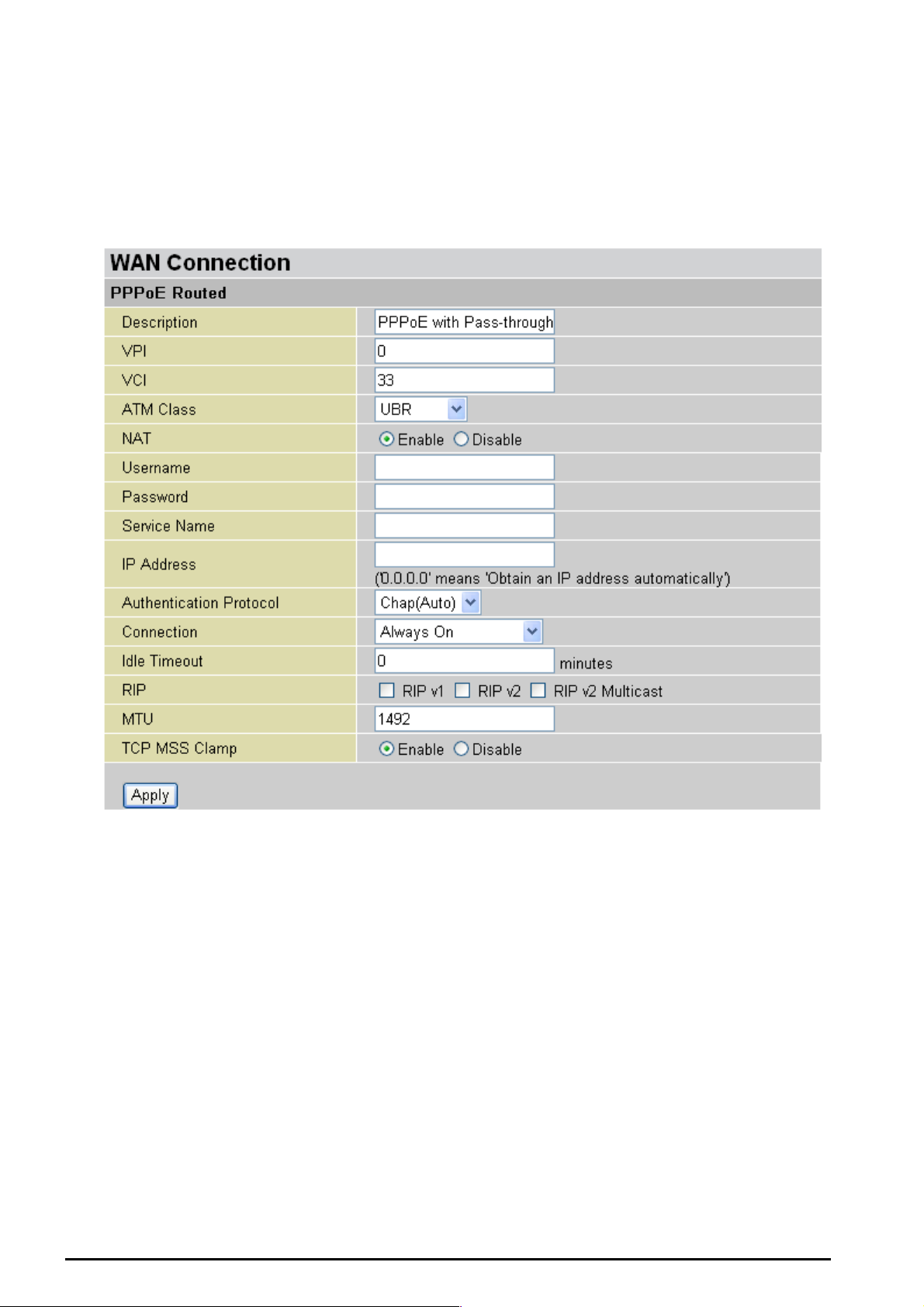
PPPoE with Pass-through Connections
PPPoE wit h pass-t hro ug h adapt s the f ollow ing m et hod: P PPoE Rout ed mo de + 14 83 Brid ge Mode. Wit h
pure PPPoE connection, the router can get one WAN address to the router. With the PPPoE and
PPPoE p as s -t hrough, concurrently , it allows us er t o have a WAN address as s igned to the router b ut also
able to get an other WAN IP f rom ISP usin g PPPoE diale r (e.g WinP oETor Windo ws XP PPPoE Dialer)
at the same time.
Description: User-definable name for this con nection.
VPI/VCI: Enter th e infor mation prov ide d by your ISP.
ATM Class: The Quality of Service for ATM layer.
NAT: The NAT (Network Address Translation) feature allows multiple users to access the Internet
through a single ISP account, sharing a single IP address. If users on your LAN have public IP
address es and can acc es s t he I nt ernet direct ly , t he NAT funct ion can be dis abled.
Username: Enter the user name provided by your ISP. You can i nput up to 128 alphanumeric charact ers
(case sensitive). This will usually be in the format of “username@ispname” instead of simply
“username”.
Password: Enter t he p ass word provi de d by y ou r I SP. Y ou c an inp ut up t o 128 alphanu meric char act ers
(case sens it iv e).
Service Name: This item is for identification purposes. If it is required, y our ISP will provide you the
information. Maxi m um input is 20 alp hanu meric charact ers .
Chapter 4:Configuration
46

TW-EA510 version 4 ADSL2+, WLAN 802.11g, VPN, Firewall Router
IP Address: specify if the Router can get an IP address from the Internet Server Provider (ISP)
automatically or not. Please click Obtain an IP address automatically via DHCP client to enable the
DHCP client function or click Specify an IP ad dres s to disable the DHCP client functi on, and s pecify the
IP address manually. The setting of this item is specif ied by your I SP.
Authentication Protocol: D ef ault is Cha p(Auto). Your ISP will advise yo u w hether to us e Chap or Pa p.
Connection:
Always on: If you want the router to establish a PPPoE session when starting up and to
automatic ally re-est ablish the PPPoE sess ion whe n dis c onnected by t he ISP.
Connect on Demand: If you want to establi sh a PPPoE session o nly when there is a packe t
requesti ng acces s to the I nternet (i.e. w hen a pro gram on y our c omputer atte mpts to ac cess th e
Internet).
Idle Timeout: Auto-d isc onnec t the br oa dban d fire w all gat eway when t here is no activ ity on t he line f or a
predetermined per iod of time.
Detail: You can define the destination port and packet type (TCP/UDP) without checking by
timer. It allows you to s et w hic h outgoin g t raf f ic w ill not trigger and reset t he idle timer.
RIP: RIP v1, RI P v 2, and RIP v2 M ult ic as t . C hec k to enabl e RIP functio n.
MTU: Maximu m Trans miss ion Unit . The size of th e larges t data gra m (exc ludi ng media -sp ecific headers )
that IP will att empt to send t hrough t he interfac e.
TCP MSS Clam p: This option he lps t o dis cover th e opt imal MT U siz e automat ic ally . Default is enabled.
Chapter 4:Configuration
47
TW-EA510 version 4 ADSL2+, WLAN 802.11g, VPN, Firewall Router
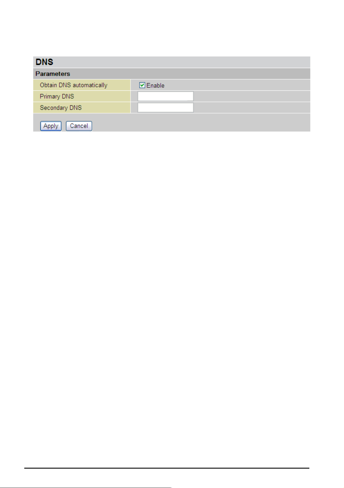
DNS
A Domain Nam e System ( DNS) contains a mapping table for do main name and IP addresses. On the
Internet, every host has a uni que and user-frie ndly name (do main name) such as www.hello world.com
and an IP address. An IP address is a 32-bit number in the form of xxx.xxx.xxx.xxx, for example
192.168. 0.254. You c an think of an IP address as a telepho ne number fo r devices o n the Intern et, and
the DNS wi ll allow you t o f ind t he telep hone numb er f or any partic ular domain name. As an I P Address is
hard to rem ember, the D N S c onverts the f riendly name into its equivale nt I P Address.
You can obtain a Domain Name System (DNS) IP address automatically if your ISP has provided it
when you logon, check the Enable box. Usually w hen you choose P PPoE or PPPoA as your W AN - ISP
protocol, t he ISP will provide the DNS IP add ress automatically . You may leave the config uration field
blank.
Alternativ ely, your ISP may provi de you with an IP address of their DNS. If this is the case, y ou must
enter the D NS IP address manually.
If you choos e one of the oth er three prot ocols R FC1483 Ro uted/Bridg ed check w ith your ISP, it may
provide y ou with an IP address for th eir DN S ser ver. You must e nter the DNS IP ad dress if y ou set the
DNS of you r PC to the LA N IP address of t his router.
Chapter 4:Configuration
48
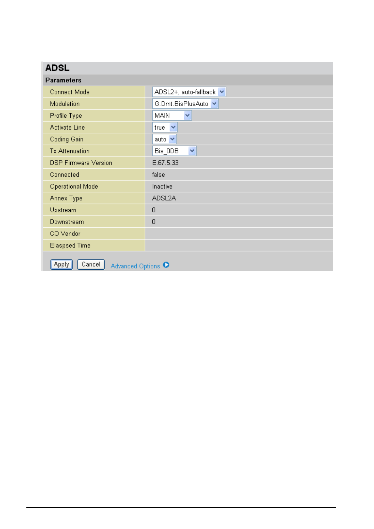
ADSL
TW-EA510 version 4 ADSL2+, WLAN 802.11g, VPN, Firewall Router
Connect Mode: This mode will automatically detect your ADSL line code, ADSL2+, ADSL2, G.dmt,
G.lite, T1.413, Ann exM2 and Annex M2 +. But in som e area, mult imode c annot detect t he ADSL li ne code
well. If it is the case, please adjust the AD SL line code to G. dmt or T1.413 first . If it still fails, please try
the other values such as ALCTL, A DI, et c . I f y ou still havi ng t rouble with the li ne, please check with your
ISP for line connect inf ormation.
Note: I f you h av e subs crib ed ADSL1 T1.413 mo de line, you may go to the A dvanc ed Options for more c onne c tion
module combinations.
Activate Line: Aborting (false) your ADSL line and making it active (true) again for taking effect with
setting of Connect Mode.
Coding Gain: It reduces rout er’s trans mit power which will eff ect to rout er’s downst ream p erformance.
Higher the gain will increase the downstream rate but it sometimes causes unstable ADSL line. The
configur able ADSL coding gain is f rom 0 dB to 7dB, or automatic.
Tx Attenuation: It is the ADSL trans mission po wer that the mode m is using. The lowe r the power the
better performance in router’s upstream. Configurable value is between 0~12.
DSP Fi rm w ar e V er si o n: Current ADSL line code fir m war e v ers ion.
Connected: Display current ADSL line sync status.
Operational Mode: Display current ADSL mode standard (Operational Mode) your Router is using
when AD SL line has sy nc .
Annex Type: ADSL Annex A, which works over a standa rd telephon e line. Annex B, which works ove r
an ISDN line.
Chapter 4:Configuration
49

TW-EA510 version 4 ADSL2+, WLAN 802.11g, VPN, Firewall Router
Upstream: Displ ay c urrent upst ream rate of y our ADSL lin e.
Downstream: Display current downstream rat e of your AD SL line.
Advanced Options
ADSL Parameters help to interpret your ADSL line s t at is t ic s .
SNR Margin: It is known as Signal t o Noise Ration Margin. It is the relative of DSL st rength to Noise
ratio. This margin is meas ure d in decibels (dB). Higher the dB figur es bette r the DSL stre ngth an d better
chance to get f as t er speed. THE HIGH ER THE B ETTER
Line Attenuation: it measures the signal loss in decibel (dB) between the CO DSLAM. Lower the
attenuation dB figur es better the D SL s t rength/s peed. THE L OWER THE BETTER.
CRC Errors: It is known as Cycl ic Redu nd ancy Chec k Err or. It s checks um is t o detect the trans mis sion
error.
Latency: I t inc ludes tw o c hannels, F as t and Interleav ed. It display s t he chann el adapted by your ISP.
Chapter 4:Configuration
50
TW-EA510 version 4 ADSL2+, WLAN 802.11g, VPN, Firewall Router
System
There are six items within the System section: Time Zone, Remote Access, Firmware Upgrade,
Backup/Restore, Restart and User Ma na ge m e n t.
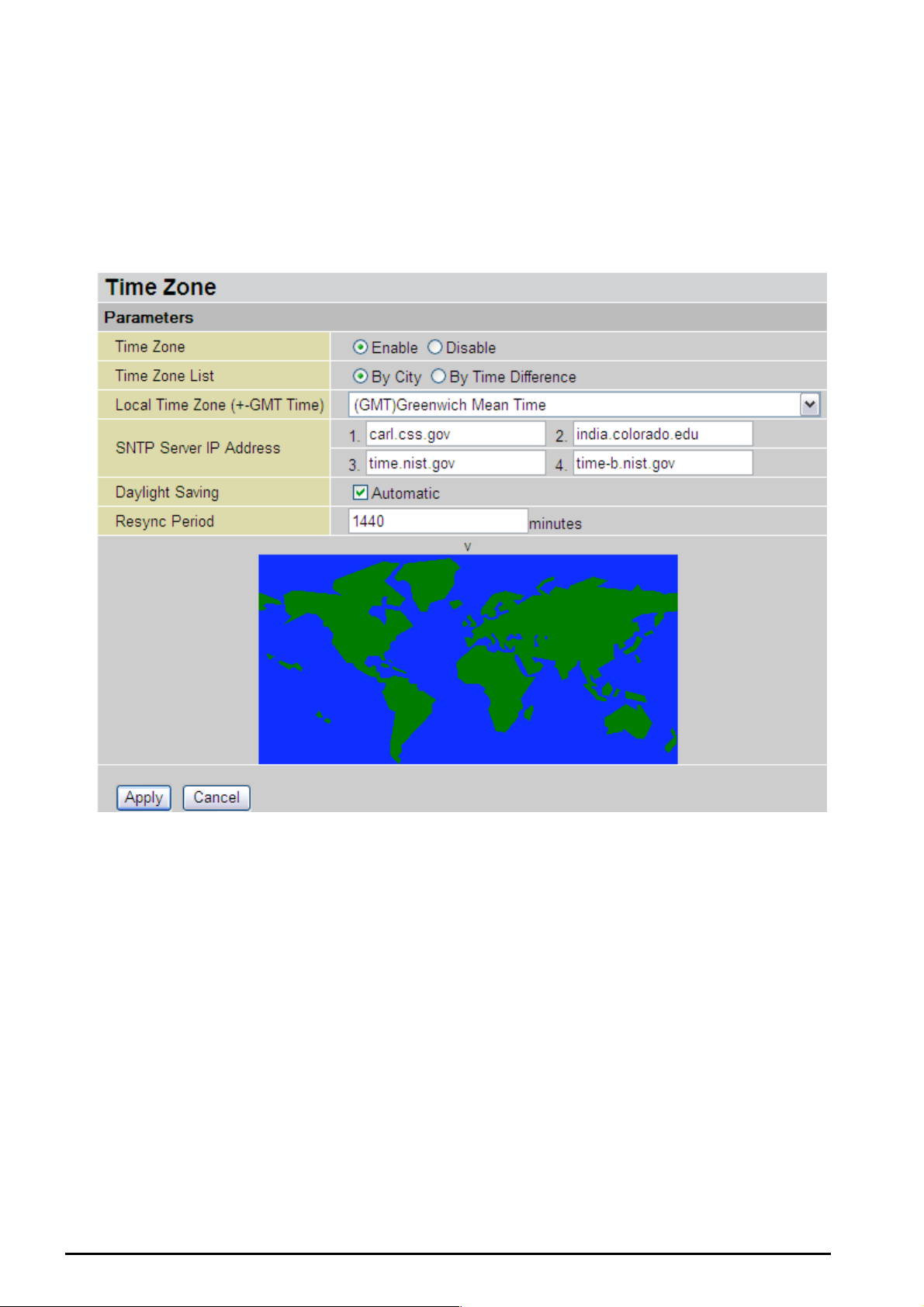
Time Zone
The router d oes not hav e a real t ime clock o n board; ins tead, it uses the Simple Network Time Pro tocol
(SNTP) to get the cur re nt time fro m an S NT P serv er outs ide y our net w ork. C hoos e yo ur loca l time z one,
click Enable and click the Apply button. After a successful connection to the Internet, the router will
retrieve the c orrect loc al t ime from the S NT P serv er y ou have s pecif ied. If you prefer t o specif y an S NTP
server other t han t hos e in the list , simply e nter it s IP addr ess as sho wn ab ove. Your I SP may p rovi d e an
SNTP serv er f or you to us e.
Daylight Saving is also known as Summer Time Period. Many places in the world adapt it during
summer t ime to move one hour of daylight from m orning to the even ing in local standa rd time. Check
Automatic box to auto set y our local tim e.
Resync Period (in minutes) is the periodic interval the router will wait before it re-synchronizes the
router’s ti me with t hat of t he sp ecified SNTP s erver. In ord er to avo id un necess arily incr easing t he loa d
on your sp ecified SNTP s erver you sho uld keep the p oll interval as hi gh as possible – at the absolut e
minimu m every few h ours or even days .
51
Chapter 4:Configuration

TW-EA510 version 4 ADSL2+, WLAN 802.11g, VPN, Firewall Router
Remote Acce ss
To temporarily permit remote administration of the router (i.e. from outside your LAN), select a time
period the ro uter will permit re mote access for a nd click Enable. You may chan ge other configur ation
options for the web administration interface using Device Management options in the Advanced
section of the GUI.
If you wish t o permane nt ly enable rem ot e ac cess, c hoose a time period of 0
minut es .
Firm wa r e U p gra de
Your router’s “fir mware ” is t he soft ware that allo ws it to operat e and prov ides all it s func tional ity. Think of
your router as a de dicated com puter, and the firm ware as the softwa re it runs. Over time this s oftware
may be improved and modified, and your router allows you to upgrade the software it runs to take
advanta ge of t hese changes.
Clicking on Browse will all ow you to s elect the ne w firmware ima ge file you hav e download ed to your
PC. Once t he c orrect file is s elected, clic k Upgrad e t o update the f irmware in y our router.
DO NOT power down the router or interrupt the firmware upgrading while
Warning
it is still in process. Improper operation could damage the router.
Chapter 4:Configuration
52

Backup / Restore
TW-EA510 version 4 ADSL2+, WLAN 802.11g, VPN, Firewall Router
These functi ons allow you to sav e and backup y our router’s curre nt settings to a file on your P C, or to
restore a previously saved backup. This is useful if you wish to experiment with different settings,
knowing that you have a backup handy in the case of any mistakes. It is advisable to backup your
router’s set t ings before making any s ignificant c hanges to yo ur router’s c onf iguratio n.
Press Back up to select wh ere on yo ur local P C to save th e s et t ings file. You may als o chang e t he nam e
of the file wh en s aving if yo u wish to keep multiple backups .
Press Browse to selec t a file from your P C to restore. You sho uld only restore s ettings files that have
been gener ated by the Backu p function, and that were created when us ing the current version of the
router’s firmware. S ettings file s saved t o y o ur PC shoul d n ot be manu al l y edited in a ny way.
After selec t ing t he settin gs f ile y ou wish to use, pressing Restore will load thos e settings into the router.
Restart Ro uter
Click Restart with option Current Settings to reboot your router (and restore your last saved
configuration).
If you wish t o resta rt the r outer us ing the f actory defa ult settin gs (for exampl e, after a firm ware u pgrade
or if you have saved an incorrect configuration), select Factory Default Settings to reset to factory
default set t ings .
Chapter 4:Configuration
53

TW-EA510 version 4 ADSL2+, WLAN 802.11g, VPN, Firewall Router
You may also res et your r oute r to fac tory s ettings by hol ding t he s mall Res et pin hole but to n mor e th an 6
seconds on t he back of y our router.
Caution: Af t er press in g the RESET but ton for more than 6 seconds, to be s u re you p owe r cycle the de vice
again.
User Ma na ge m en t
In order to preve nt unauthorized ac cess to your router’s configuration interf ace, it requires all users to
login with a p as sword. Y ou c an set up m ult iple user acc ounts, each with the ir own pass w ord.
You are able to Edit existing users and Create new users who are able to access the device’s
configur at ion interfac e. Once you have clicked on Edit, you are shown th e f ollowing options:
You can change the user’s password, whether their account is active and Valid, as well as add a
comment to each user account. These options are the same when creating a user account, with the
exception that once created you cannot change the username. You cannot delete the default admin
account, however yo u c an delete a ny ot her created account s by c lic k ing Delete wh en editi ng the user.
You are st rongly advis ed t o change the password on the def ault “admin” account when you rec eive your
router, an d any t ime you res et y our configuration to F ac t ory Defaults.
Chapter 4:Configuration
54

TW-EA510 version 4 ADSL2+, WLAN 802.11g, VPN, Firewall Router
Firewall and Access Control
Your router i ncludes a full SPI ( Stateful Packet Ins pection) firewall f or controlling Intern et access fro m
your LAN, as well as helping to prevent attacks from hackers. In addition to this, when using NAT
(Network Address Tr anslation. Please see t he WAN config uration s ection for more details on NAT) t he
router acts as a “natural” Int ernet firewall, as all PCs on your LAN will use private IP addresses that
cannot be direc t ly ac cesse d f rom the Internet.
Firewall: Prevents access from outside your network. The router provides three levels of security
support:
NAT natural firewall: This masks LA N users’ IP addresses which are inv isible to out side users on the
Internet, making it much more difficult for a hacker to target a machine on your network. This natural
firewall is on when NAT function is enabled.
When using Virtual Servers your PCs will be exposed to the degree
specified in your Virtual Server settings provided the ports specified are
opened in your firewall packet filter settings.
Firewall Security and Policy (General Settings): Inbound direction of Packet Filter rules to prevent
unauthoriz ed comput ers or app lic at ions access ing your local network f rom the Internet.
Intrusio n Detecti o n: Enable Intrusi on Detection to detect, prevent and log malicious attacks.
Access Control: Prevents acc es s f rom PCs on your local n etwork:
Firewall S ecurity and P olicy (General S ettings): Outbou nd direction of Packet Filter ru les to prevent
unauthoriz ed comput ers or app lic at ions access ing the Int ernet.
URL Filter: To bloc k PCs on you r loc al network f rom unwant ed websites.
Chapter 4: Config uratio n
55
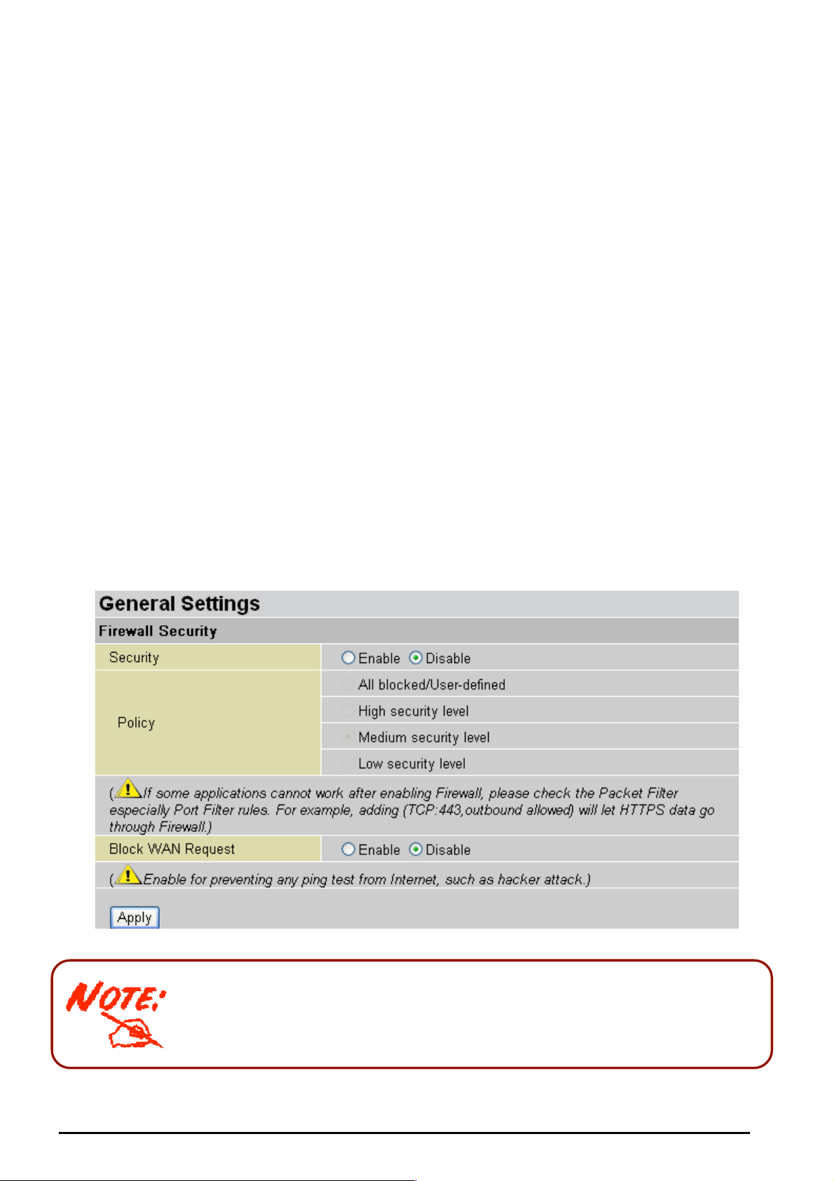
TW-EA510 version 4 ADSL2+, WLAN 802.11g, VPN, Firewall Router
Here are the ite ms within th e Firewall section: G eneral Settings, Packet Filter, Intrusion Dete ction,
URL Filter, IM/P2P Blocking and Firewall Log.
General Settings
You can choose not to enable Firewall, to add all filter rules by yourself, or enable the Firewall using
preset filt er rules and modif y the port filter r ules as required. The Packet F ilter is used to filte r packets
based-on Applications (Port) or IP addr es s es .
There are f our options when you enable th e Fi rewall, they are:
All blocked/ U ser -define d: no pre-def ined port or address filter rules by def ault, me aning that all
inbound (Internet t o LAN) and outbound (LAN to Intern et ) packets w ill be blocked. Users have to
add their own filter rul es f or f urt her access t o t he Internet .
High/Medium/Low security level: the predefined port filter rules for High, Medium and Low
security ar e displayed in Port Filt ers of Packet Filt er.
Select eith er Hi gh, Medi um or Low security level to enable the Fire wall. The only dif ferenc e betw een
these thre e security lev els is the pres et port filter rules in the Pack et Filter. Fire wall functiona lity is the
same for all l evels; it is only the list of pres et port f ilters that chang es between e ach setting. For more
detailed on level of preset port filt er informat ion, refer t o T able 1: Pre de fi n ed Port Filter .
If you choose of the preset secu rity levels and t hen add custo m filters, you may t emporarily dis able the
firewall an d recover y our c us tom filter s et t ings by re-s electing t he s ame secu rit y lev el.
The “Block WAN Request” is a stand-alone function and not relate to whether security enable or
disable. Most ly it is f or preventing any sca n t ools from W AN site by hac k er.
Any remote user who is attempting to perform this action may result in
blocking all the accesses to confi gure and manage of the devi ce from the
Internet.
Chapter 4: Config uratio n
56

TW-EA510 version 4 ADSL2+, WLAN 802.11g, VPN, Firewall Router
Packet Filter
This function is only available when the Firewall is enabled and one of these four security levels is
chosen (All bl ocked, High, Medi um and Low). The predefi ned port filter rules in the Packet Filter must
modify acc ordingly to the l evel of Firew all, which is select ed. See Table1: Predefined Port Filter for
more detaile d infor mation.
Example: Predefined Port Filters Rules
The predef ined port filt er rules for H igh, Medium and Lo w sec urity levels are listed. See Table 1.
Note: Firewall – All Blocked/User-de fined, you must d efine and create the port filter rules yours elf. No pred efined
rule is being preconfigured.
57
Chapter 4: Config uratio n

TW-EA510 version 4 ADSL2+, WLAN 802.11g, VPN, Firewall Router
Table 1: Pr edefine d P ort Filter
Application Protocol
Port
Number
Start End Inbound Outbound Inbound Outbound Inbound Outbound
Firewall - Lo w Fi r ewal l - Medium Firewall – Hi gh
HTTP(80) TCP(6) 80 80 NO YES NO YES NO YES
DNS (53) UDP(17) 53 53 NO YES NO YES NO YES
DNS (53) TCP(6) 53 53 NO YES NO YES NO YES
FTP(21) TCP(6) 21 21 NO YES NO YES NO NO
Telnet(23) TCP(6) 23 23 NO YES NO YES NO NO
SMTP(25) TCP(6) 25 25 NO YES NO YES NO YES
POP3(110) TCP(6) 110 110 NO YES NO YES NO YES
NEWS(NNTP)
(Network News
Transfer Protocol)
TCP(6) 119 119 NO YES NO YES NO NO
RealAudio/
RealVideo
UDP(17)
7070 7070 YES YES YES YES NO NO
(7070)
PING ICMP(1) N/A N/A NO YES NO YES NO YES
H.323(1720) TCP(6) 1720 1720 YES YES NO YES NO NO
T.120(1503) TCP(6) 1503 1503 YES YES NO YES NO NO
SSH(22) TCP(6) 22 22 NO YES NO YES NO NO
NTP /SNTP UDP(17) 123 123 NO YES NO YES NO YES
HTTP/HTTP
Proxy (808 0)
TCP(6) 8080 8080 NO YES NO NO NO NO
HTTPS(443) TCP(6) 443 443 NO YES NO YES N/A N/A
ICQ (5190) TCP(6) 5190 5190 YES YES N/A N/A N/A N/A
MSN (1863) TCP(6) 1863 1863 YES YES N/A N/A N/A N/A
MSN (7001) UDP(17) 7001 7001 YES YES N/A N/A N/A N/A
MSN VEDIO
(9000)
TCP(6) 9000 9000 NO YES N/A N/A N/A N/A
Inbound: Internet to LAN; Outbound: LAN to Internet.
YES: Allowed; NO: Blocked; N/A: Not Appl ic able
Chapter 4: Config uratio n
58
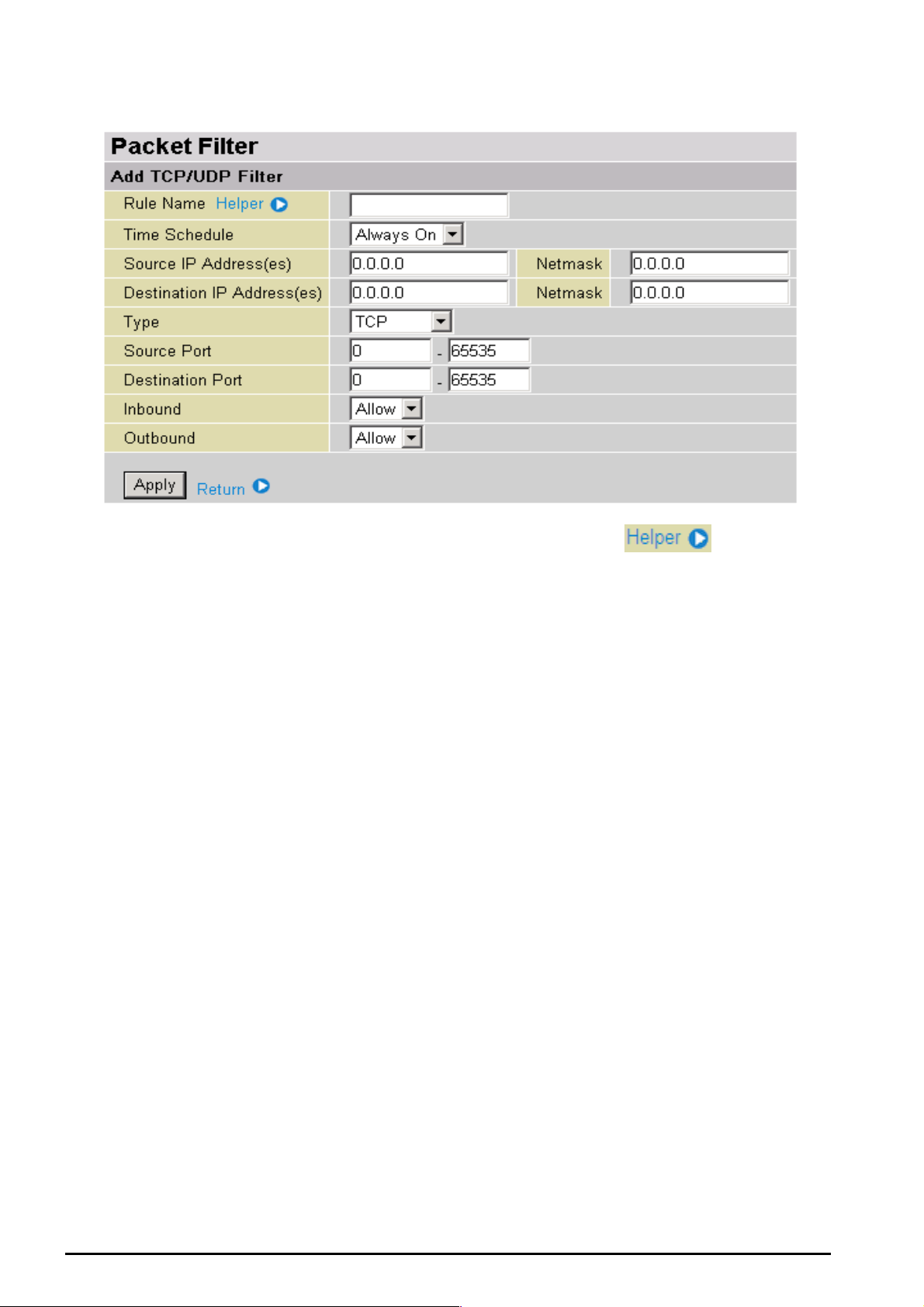
Packet Filter – Ad d TC P/UDP Filter
TW-EA510 version 4 ADSL2+, WLAN 802.11g, VPN, Firewall Router
Rule Name: Users-define description to identify this entry or click
predefined rules. T he maximu m name length is 32 charact ers.
Time Schedule: It is self-defined ti me period. You may specif y a time sch edule for your prioritization
policy. For setup and det ail, refer to Time Schedu le section
Source IP Address (es) / De stinati on IP Ad dress(e s): This is t he Address-Filter us ed t o allow or block
traffic to/ from partic ula r IP addr ess(es ). Select ing the S ubnet Mask of the IP address rang e you wis h t o
allow/block t he traffic t o or f orm; set I P address and Subnet Mask to 0.0.0.0 to inac t iv e t he Addres s -Filter
rule.
Tip: To block access,. to/from a single IP address, enter that IP address as the Host IP Address and
use a Host Subnet Mask of “255.25 5. 255.255”.
Type: It is the packet protocol type used by t he application, selec t TCP, UDP or both TCP/UDP
Source Port: This Port or Port Ranges defines the port allowed to be used by the Remote/WAN to
connect t o the a pplicatio n. D efault is set fro m ra nge 0 ~ 65535. It is recomm ended t hat this opti on be
configur ed by an advanced user.
Destination Port: This is t he Port or Po rt R anges that def ines the application.
Inbound / Outbound: Select Allow or Block the access to the Internet (“Outbound”) or from the
Internet (“Inbound”).
to select existing
Click Apply button to apply your changes.
Chapter 4: Config uratio n
59

Packet Filter – Add Raw IP Filter
TW-EA510 version 4 ADSL2+, WLAN 802.11g, VPN, Firewall Router
Rule Name: Users-define description to identify this entry or click
to select existing
predefined rules.
Time Schedul e: It is s elf -def ined time period. Yo u m ay s pecify a tim e s c hedule for your priorit iz at ion
policy. For setup and det ail, refer to Time Schedu le section
Prot oc ol N um be r: Insert the port number, i. e. GRE 47.
Inbound / Outbound: Select Allow or Block the access to the Internet (“Outbound”) or from the
Internet (“Inbound”).
Click Apply button to apply your changes.
Chapter 4: Config uratio n
60
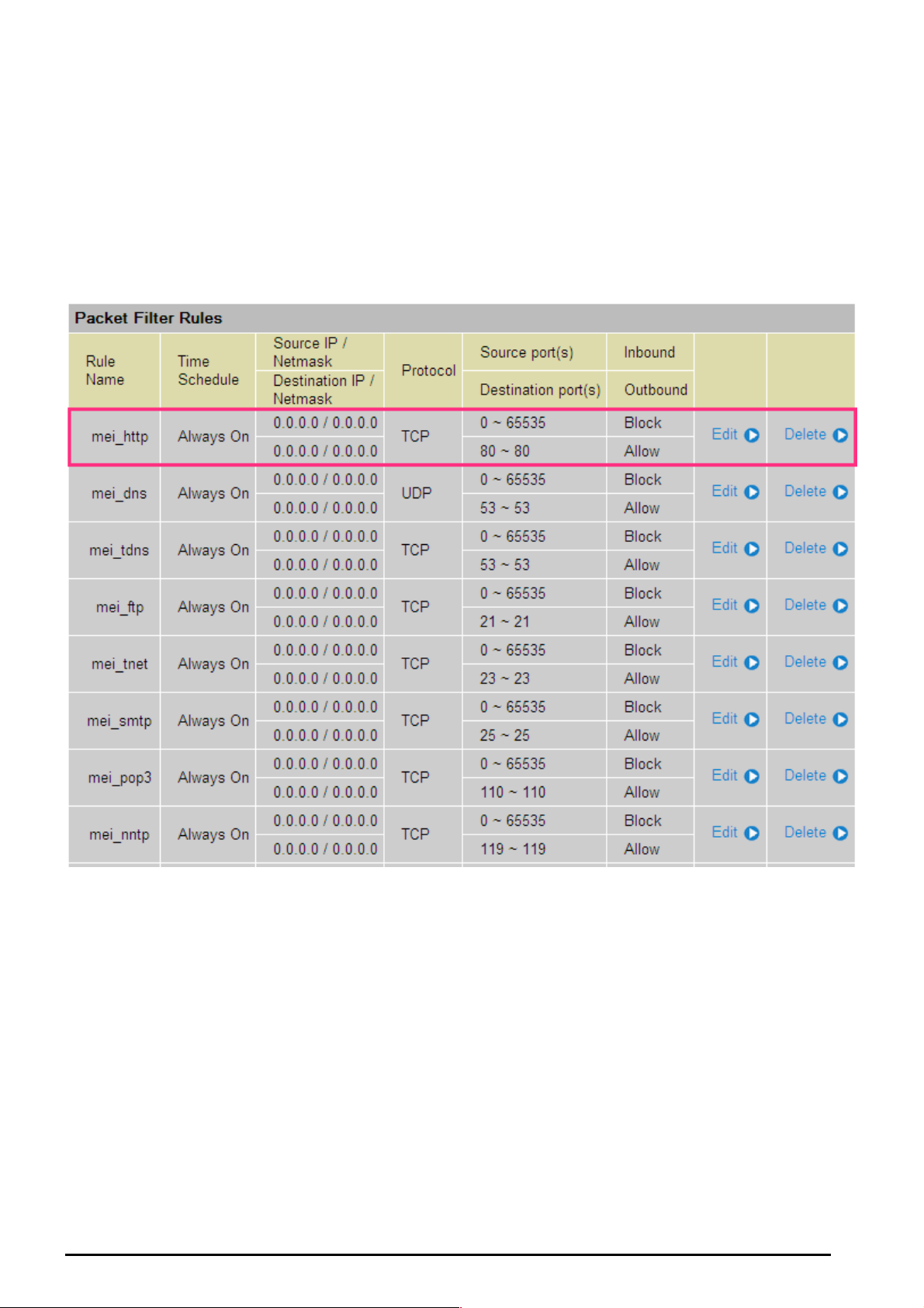
TW-EA510 version 4 ADSL2+, WLAN 802.11g, VPN, Firewall Router
Example: Configuring your firewall to allow for a publicly accessible web server on your LAN
The predefi ned port filter rul e for H TTP (T CP port 80) is the sa me no matt er wh eth er the fire wall is set t o
a high, medium or low security level. To setup a web server located on the local network when the
firewall is enabled, you have to c onf igure the Port Filters set t ing f or HTTP.
As you can see from the diagram below, when the firewall is enabled with one of the three presets
(Low/Medi u m/Hi gh), i nbou nd HTTP acces s is n ot allo wed whic h m eans rem ote acces s thr oug h H TTP t o
your route r is not allowed.
Note: Inbound indicates accessing from Internet to LAN and Outbound is from LAN to the Internet.
Chapter 4: Config uratio n
61

TW-EA510 version 4 ADSL2+, WLAN 802.11g, VPN, Firewall Router
Configuring Packet Filter:
1. Click Packet Filter. You will t hen be pres ented with the predefined port filt er rules screen (in this c ase
for the low s ec urit y level), sh own belo w:
Note: You may c lick Edit the predefined rule instead of Delete it. This is an example to show to how you add a
filter on your own.
Click Delete
2. Click Delete to delete th e ex isting HT T P rule.
3. Click Add TCP/UDP Filter.
Click Add TCP/UDP Filter
4. Input the Rule Name, Time Sc hedule, Source/Destination IP , Type, Source/Destination Port , Inbound
and Outbound.
Example :
Application: Cindy_HTTP
Time Schedule: Al ways On
Source / D es t ination IP Address(es): 0.0.0.0 (I do not wis h to active the a ddress-fi lter, inste ad I
use the port-filter)
Type: TC P (Please r ef er t o Table1: Predefin ed Port Filte r)
Source Port : 0-65535 (I allow all ports to connect with the application))
Redirect Port: 80-80 (This is Por t defined f or HTTP)
Inbound / Out bound: Allow
Chapter 4: Config uratio n
62

TW-EA510 version 4 ADSL2+, WLAN 802.11g, VPN, Firewall Router
5. The new port filter rule for HT TP is s hown bel ow:
6. Configure yo ur Virtu al Serv er (“p ort for warding” ) set tings s o that inco ming HTT P request s on p ort 80
will be for war ded to the PC running your web server:
Note: For how to configure the HTTP in Virtual Server, go to Add Virtual Server in Virtual Server section for more
.
details
Chapter 4: Config uratio n
63

Intr usion De t e ction
TW-EA510 version 4 ADSL2+, WLAN 802.11g, VPN, Firewall Router
The router’s Intrusion Detection System (IDS) is used to detect hacker attacks and intrusion attempts
from the I nternet. If the IDS f unction of the fi rewal l is ena bled, in boun d packet s are filtered and b locked
depending on whether they are detected as possible hacker attacks, intrusion attempts or other
connections that the router determines t o be suspic ious .
Blacklist: I f the rout er det ects a possibl e att ack, the sourc e IP or dest inat ion I P addres s will be ad d ed to
the Blacklis t. Any furt her attempts using this IP address will be block ed for the ti me period sp ecified as
the Block Duration. The default setting for this function is false (disabled). Some attack types are
denied i m me diately without using t he Blacklis t f unction, suc h as Land attack and Echo/CharGen scan.
Intrusio n Detecti o n: If enabled, IDS wil l bloc k Smurf at t ac k at t empts. Default is false.
Block Durati on:
Victim Protection Block Duration: T his is the duration f or blocking Smurf attacks. Default value
is 600 seconds.
Scan Attack Block Duration: This is the duration for blocking hosts that attempt a possible
Scan attack. Scan attack types include X’mas scan, IMAP SYN/FIN scan and similar att empts.
Default va lue is 86400 seconds.
DoS Attack Block Duration: This is the duration for blocking hosts that attempt a possible
Denial of Servic e (DoS) attack. Pos sible DoS atta cks this attempts to block include Ascend Ki ll
and WinNuke. Default value is 1800 seconds .
Max TCP Open Handshaking Count: This is a threshold value t o decid e wheth er a SY N Flood attempt
is occurring or not. Default value is 100 TCP SYN per sec onds.
Max PING Count: This is a thres hold val ue to decide whether a n ICMP Ech o Storm is oc currin g or not.
Default va lue is 15 IC MP Ec ho Request s (PING) per s ec ond.
Max ICMP Count: This is a t hreshold to decid e whether an ICMP flood is occurrin g or not. Default value
is 100 ICM P pac kets per seconds ex c ept ICMP Echo Requests (PING).
For SYN Flood, ICMP Echo Storm and ICMP flood, IDS will just warn the user in the Event Log. It
cannot pr ot ec t against such attacks.
Chapter 4: Config uratio n
64

TW-EA510 version 4 ADSL2+, WLAN 802.11g, VPN, Firewall Router
Table 2: Ha cker attac k types recognize d by t h e IDS
Intrusio n Name Detect Para meter Bla ckli st
Ascend Kill Ascend Ki ll data Src I P DoS Yes Yes
WinNuke
Smurf
Land a tt ac k SrcIP = DstIP Yes Yes
Echo/CharGen Scan
Echo Sca n
CharGen Scan
X’mas Tree Sca n TCP Flag: X’mas Src IP Scan Yes Yes
TCP
Port 135, 137~139,
Flag: URG
ICMP type 8
Des IP is bro adcast
UDP Echo Port and
CharGen Port
UDP Dst Port =
Echo(7)
UDP Dst Port =
CharGen(19)
Src IP DoS Yes Yes
Dst IP
Yes Yes
Src IP Scan Yes Yes
Src IP Scan Yes Yes
Type of Block
Duration
Victim
Protection
Dro p Pac k e t Show Log
Yes Yes
IMAP
SYN/FI N Sca n
SYN/FIN/RST/ACK
Scan
Net Bus Scan
Back Orifi ce Scan
SYN Flood
ICMP Flood
ICMP Echo
Src IP: Source IP Src Port: Source Port
Dst Port: Destination Port Dst IP: Dest ination IP
TCP Flag: SYN/FIN
DstPort: IMAP(143)
SrcPort: 0 or 65535
TCP,
No Existing session
And Scan Hosts
more than five.
TCP
No Existing session
DstPort = Net Bus
12345,12346, 34 56
UDP, DstPort =
Orifice Port (3133 7)
Max TCP Open
Handshaking Count
(Default 100 c/sec)
Max ICMP Count
(Default 100 c/sec)
Max PING Count
(Default 15 c/sec)
Src IP Scan Yes Yes
Src IP Scan Yes Yes
SrcIP Scan Yes Yes
SrcIP Scan Yes Yes
Yes
Yes
Yes
Chapter 4: Config uratio n
65
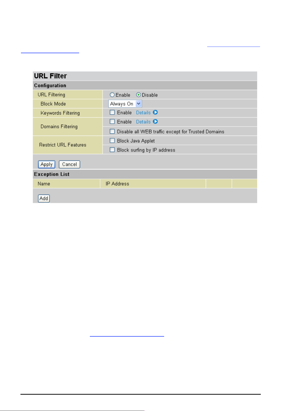
URL Filter
TW-EA510 version 4 ADSL2+, WLAN 802.11g, VPN, Firewall Router
URL (Uniform Resource Locator – e.g. an address in the form of http://www.abcde.com
http://www.example.com
) filter rules allow you to prevent users on your network from accessing
or
particular websites by their URL. There are no pre-defined UR L filter rules; you c an add filter rul es to
meet your requirem ent s .
Enable/Disable: To en able or disable URL Filt er feature.
Block Mode: A list of t he mod es th at y ou c an c hoos e t o ch eck t he URL filt er r ules. The def ault is set to
Always O n.
Disabled: No ac t ion will be p erf ormed by t he Block M ode.
Always O n: Action is ena ble d. URL filte r ru les will be mo nitori ng an d ch eck ing at all ho urs of th e
day.
Time Sl ot1 ~ Tim eSl ot 16: It is self -def ined time period. You m ay s pec if y t he time period to check
the URL filter rules, i.e. during working hours. For setup and detail, refer to Time Schedule
section.
Key words Fil tering: Allows blocking by specific k eywor ds within a p articular URL rather t han hav ing to
specify a complete URL (e.g. to block any image called “advertisement.gif”). When enabled, your
specified keywords list will be checked to see if any keywords are present in URLs accessed to
determine if the connection attempt should be blocked. Please note that the URL filter blocks web
browser ( H T T P) c onnection at t empts using port 8 0 only .
For example, if the URL is http://www.abc.com/abcde.html
, it will be dropp ed as the keyword “abc de”
occurs in th e URL.
Domain s Filteri ng: This function c hecks the whole URL not t he IP ad dress, in URLs accesse d ag ainst
your list of do mai ns to bloc k or allow. I f it is matched, t he U RL re ques t will be s ent (Trust ed) o r dro ppe d
(Forbidde n). For this funct ion t o be activ ate d, bot h chec k-b oxes must be c hec ked. H ere is the c hec king
procedure:
Chapter 4: Config uratio n
66
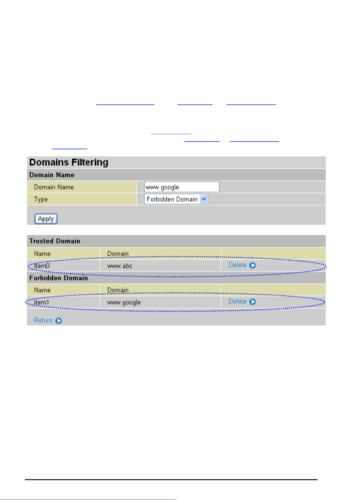
TW-EA510 version 4 ADSL2+, WLAN 802.11g, VPN, Firewall Router
1. Check the dom ain in t he U RL to det er mine if it is in t he trust ed lis t. I f yes , the c onnecti on att em pt
is sent to the remote w eb s erver.
2. If not, c hec k if it is lis t ed in t he f orbidden lis t . I f y es, then the conn ec tion atte mpt will be dropped.
3. If the pac k et does not m at c h eit her of the above tw o it ems, it is sent t o t he remote we b s erver.
4. Ple ase be note t hat the complet ed URL, “ www” + domai n name shall b e specified. For exam ple
to block traff ic t o www.google.com.au
, enter “ www.google” or “www.google.com”
In the exa mple b elo w, th e U RL req uest f or www.a bc.com
will be se nt to t he re mot e we b serv er b ec ause
it is listed i n the tr ust ed lis t, w hilst th e U RL re ques t for www.google
because www.google
is in the forbidden list.
or www.google.com will be dr opped,
Example: Andy wishes to disa ble all WEB traffi c except for ones listed in the trus ted domain, which
would prevent Bobby from accessing other web sites. Andy selects both functions in the Domain
Filtering and thinks that it will stop Bobby. But Bobby knows this function, Domain Filtering, ONLY
disables all WEB traffic exc ept for Trusted Domain, BUT not its IP address. If this is the situ ation,
Block surfing by IP address function can be handy and helpful to Andy. Now, Andy can prevent
Bobby fro m ac c es s ing other sit es .
Restrict U R L F eatures: T his f unc t ion enhances the rest riction to your URL rules.
Block Java Applet: This fu nctio n can block Web content that incl udes the J ava Applet. I t is to
prevent someone who wants to damage your system via standard HTTP protocol.
Block surfing by IP address: Preventing someone who uses the IP address as URL for
skipping Do m ains Filteri ng f unction. Ac t iv at es only and if Domain Fi ltering ena bled.
67
Chapter 4: Config uratio n
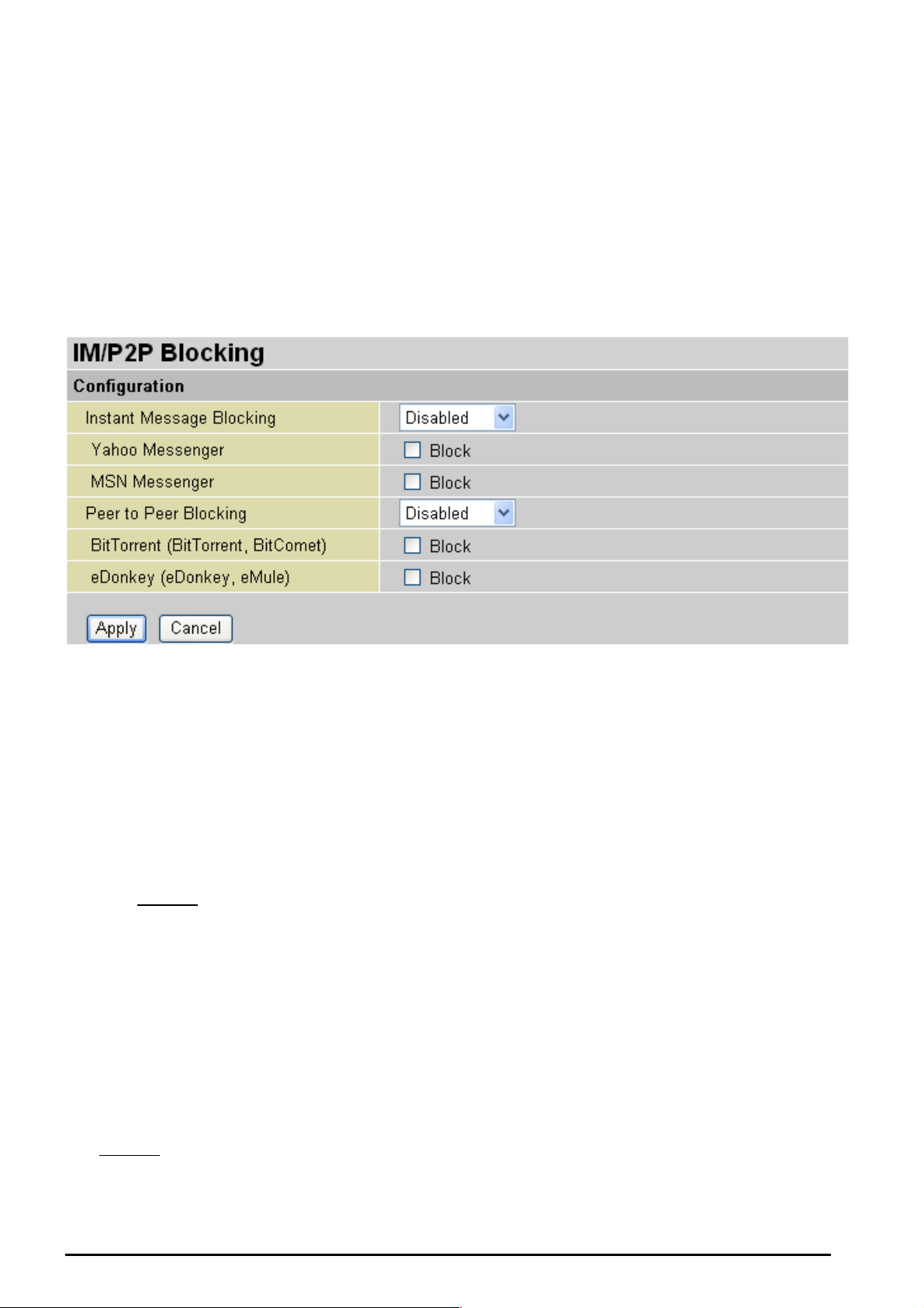
TW-EA510 version 4 ADSL2+, WLAN 802.11g, VPN, Firewall Router
IM / P2P Blocking
IM, short for Instant Message, is required to use client program software that allows users to
communic ate, in exchang ing text messa ge, with other I M use rs in real time ove r the Internet. A P2P
application, known as Peer-to-peer, is group of computer users who share file to specific groups of
people acr oss the Intern et. Both Insta nt Message an d Peer-to-pe er applicatio ns make com munication
faster and e asier but y our n etw ork ca n bec o me in creasi ngly i nsec ure at t he sa me ti me. Tele Well IM and
P2P blockin g helps users t o restric t LA N PCs to ac cess to the c ommonly used IM, Ya ho o and M SN, and
P2P, Bit Tor rent and e Do nk ey , applicatio ns ov er t he Internet .
Instant Message Blocking: The default is s et t o Disabled.
Disabled: Instant Message bloc ki ng is not trigger ed. No action wil l be perfor med.
Always On : Ac t ion is enab led.
TimeSl ot1 ~ Tim eSlot 16: This is the self-def ine d tim e perio d. You m ay spec ify t he time pe rio d
to trigger the bloc king, i.e. during worki ng hours. For setup and d etail, refer to Time Schedule
section.
Yahoo/MSN Messenger: Check the box t o bloc k either or both Y ahoo or/and MSN M esseng er. T o be
sure you en abled
Peer to Pe er Blockin g: The default is s et t o Disabled.
Disabled: Instant Message bloc ki ng is not trigger ed. No action wil l be perfor med.
Always On : Ac t ion is enab led.
TimeSlot1 ~ TimeSlot16: This is t he s elf-defined time period. You m ay s pec if y t he t ime period
to trigger the bl ocking, i. e. during work ing hours. Fo r setup and det ail, refer to Time Schedule
section.
the Insta nt M es s age Blocking first.
BitTorrent / eDonkey: Check the box to bl ock either or both Bit Torrent or/and e Donkey. To be sure
you enabled
Chapter 4: Config uratio n
the Peer t o Peer Blocking first.
68
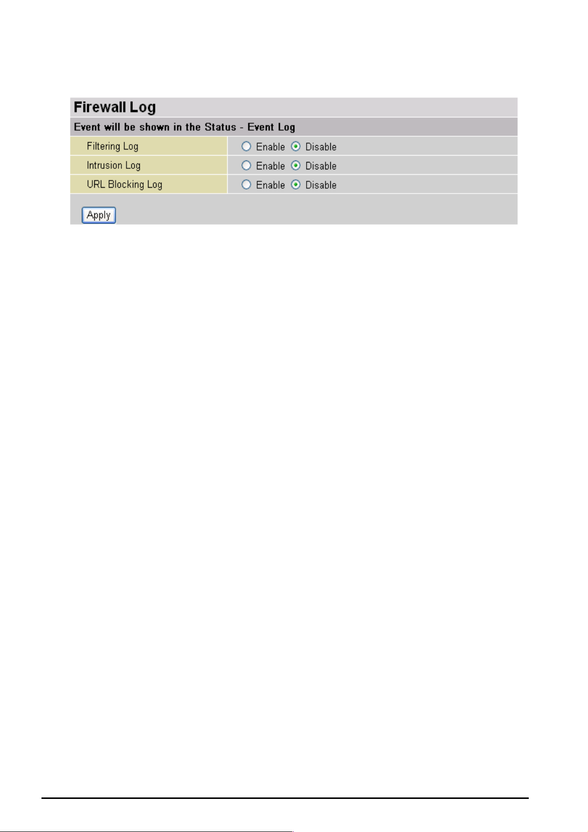
TW-EA510 version 4 ADSL2+, WLAN 802.11g, VPN, Firewall Router
Firewall Log
Firewall L og display log informat ion of any unexpect ed ac t ion with yo ur f irewall settings.
Check the Enable box to activate t he logs.
Log inform at ion can be seen in the Status – Event Log after en abling.
Chapter 4: Config uratio n
69
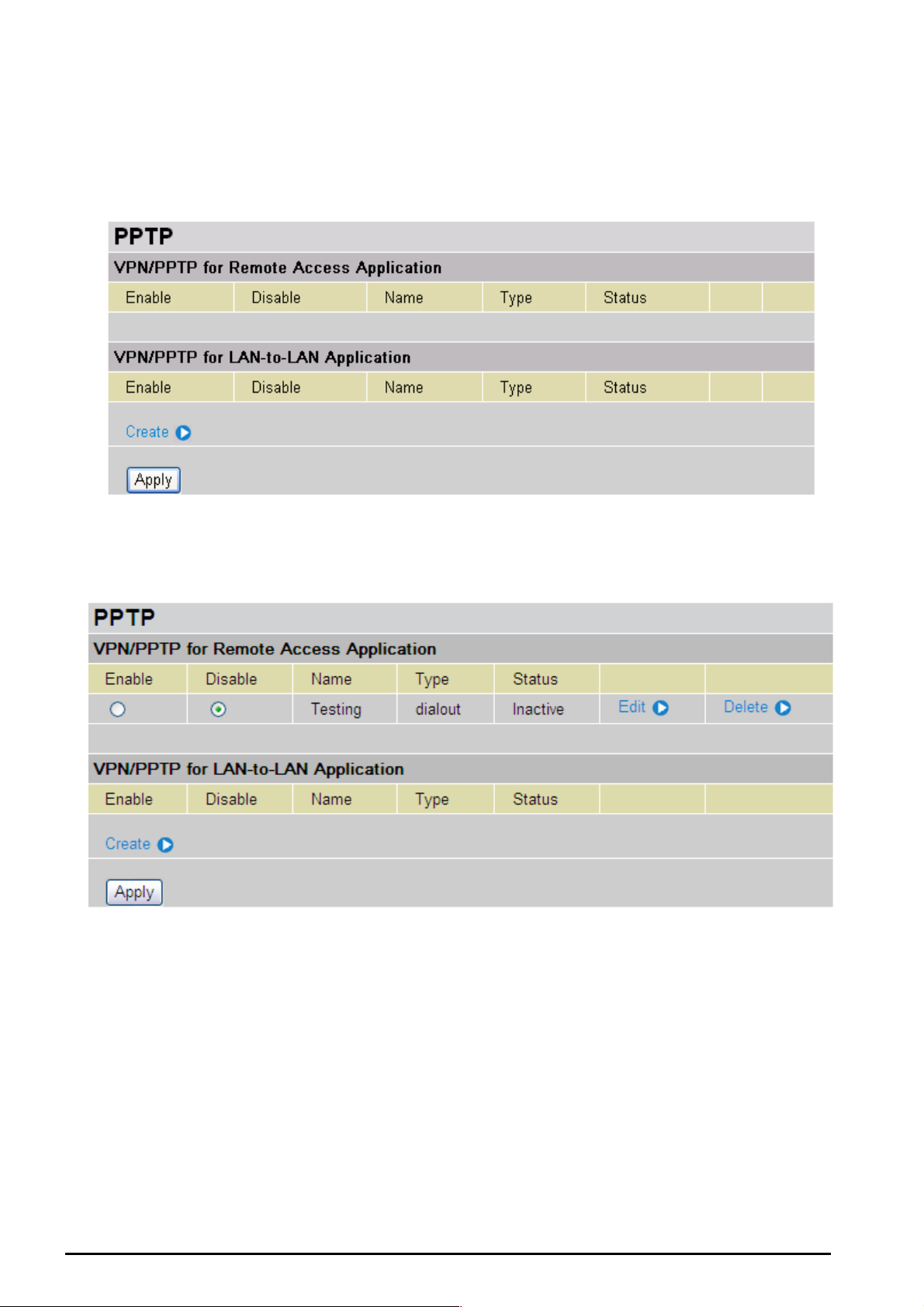
TW-EA510 version 4 ADSL2+, WLAN 802.11g, VPN, Firewall Router
VPN (Virtual Private Networks)
Virtual Private Networks is ways to establish secured communication tunnels to an organization’s
network v ia t he I nt ernet. Your router supports t hree main ty pes of VPN (Virtual Private Network), PPTP
PPTP (Point-to-Point Tunneling Protocol)
There are two types of PPTP V PN support ed; Remote Access and LAN-to-LAN (ple as e refer be low for
more infor m at ion.). Click Create to configure a new VPN co nnection.
After you have creat ed PPTP connection, ac c ount st at us will be displayed. (See exa m ple above ).
Enable / Disable: This function activates or deac t iv at es t he PPTP connection. To wish
interrupti ng t he tunnel, c heck Disable radi o button and c lic k Apply button to deac t ivate the
connection.
Name: This is the user-defin ed name of t he c onnection.
Type: This refers t o y our router op erates as a client or a server, Dialout or Dialin in respec t ively.
Status: It inf orms your PPTP tunnel connect ion condition.
Chapter 4: Configuration
70
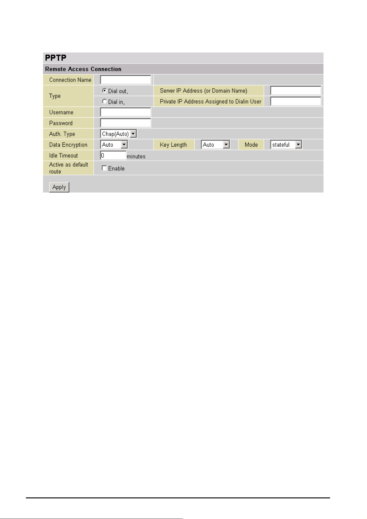
PPTP Connection - Remote Access
TW-EA510 version 4 ADSL2+, WLAN 802.11g, VPN, Firewall Router
Connection Name: A user-defined nam e f or t he connect ion (e.g. “c onnection t o of f ic e”).
Type: Check Dial Out if y ou want y our rout er t o operat e as a client (connect ing to a r emote VPN server,
e.g. your of f ic e s erv er), check Dial In operates as a VPN server.
When configuring your router as a Client, enter the remote Server IP Address (or Domain
Name) you wish to connection t o.
When config uring your route r as a server, enter the Private IP Address Assi gned to Dial in
User addr es s .
Username: If you a re a Dial-O ut user (clie nt), enter the us ernam e provided by your Host . If you are a
Dial-In user (server), enter your own username.
Password: If you are a Dial-Out user (client ), enter the pass word provide d by your Host. If you are a
Dial-In user (server), enter your own pass w ord.
PPP Authe nticatio n Type: Default is Aut o if you want the ro ut er t o deter min e t he authentication type to
use, or else manua lly sp ecify CH AP (C hallenge Hands hake A uthenticat ion Pr otocol ) or PAP ( Pass word
Authentic ation Prot ocol) if y ou kno w which type th e server is us ing (wh en acting as a client), or else the
authentication type you want clients connecting to you to use (when acting as a server). When using
PAP, the pass word is sent un encrypted, whilst CHAP encry pts the pass word before sen ding, and also
allows for c hallenges at dif f erent perio ds t o ensure that an int ruder has not replaced the client.
Data Encry ption: Data sent ov er th e VP N con nec tion ca n be encry pted by a n MPPE algorit hm. De fault
is Auto, so that this setting is negotiated when establishing a connection, or else you can manually
Enable or Disable encrypt ion.
Key Length: The data can be encry pte d by MPP E algorit hm with 4 0 bits or 1 28 bits. Default is Auto, it
is negotiated when establishing a conn ec t ion. 128 bit k ey s prov ide stronger encrypt ion than 4 0 bit keys.
Mode: You may select Stateful or Stateless mode. T he key will be changed ev ery 256 packets when
you select St at ef ul mode. I f y ou s elec t St ateless m ode, the key will be changed in eac h packet.
Idle Time: Auto-disconnect the VPN connection when there is no activity on the connection for a
predetermined per iod of time. 0 means this c onnec t ion is always on.
Chapter 4: Configuration
71
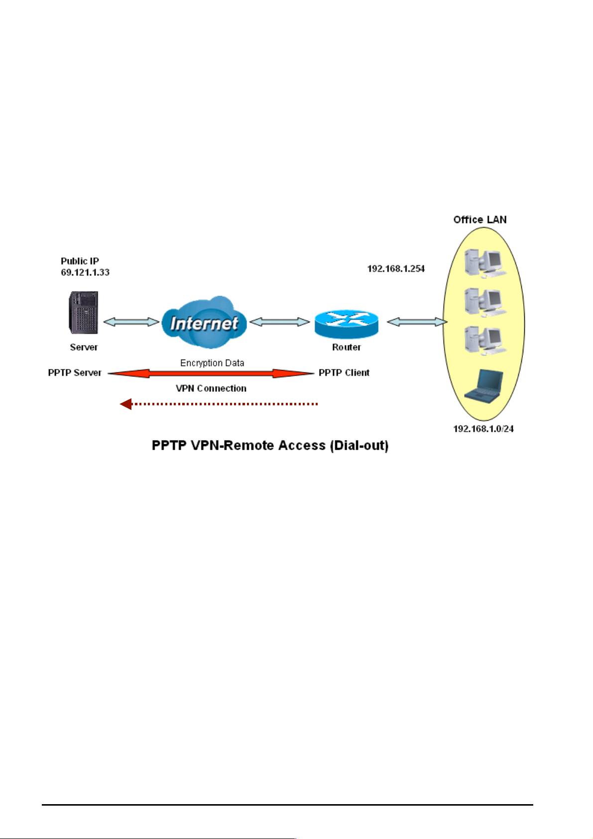
TW-EA510 version 4 ADSL2+, WLAN 802.11g, VPN, Firewall Router
Active as d efault rout e: Enables the default route.
Click Apply button to apply your changes.
Example: Configuring a Remote Access PPTP VPN Dial-out Connection
A company’s office est ablishes a PPTP VP N connection with a file server locat ed at a separate locat ion.
The router is installed in the office, c onnected t o a couple of PCs and Servers.
Dial-out
Chapter 4: Configuration
72

TW-EA510 version 4 ADSL2+, WLAN 802.11g, VPN, Firewall Router
Configuring the PPTP VPN in the Office
You can eit her input the I P address (69.1.121.33 in this c as e) or hostname to reac h t he server.
Item
1 Connect ion Name VPN_PP TP Given nam e of PPTP connection
Dial out Check Dia l out
2
Server IP A ddress
(or Domain name)
Username username
3
Password 123456
Auth.Type Chap(Auto)
Data Encryption Auto
4
Key Lengt h Auto
Mode stateful
5 Idle Time 0
Function Description
69.121.1.33 An Dialed server IP
A given use rname & password
Keep as default value in most of the cases,
PPTP server & client will determine the value
automatic ally . Ref er t o ma nual f or det ails if yo u
want to change the setting.
The conn ec t ion will be disc onnected when there
Is no traffic in a predef ined peri od of ti me. Idle
time 0 means the connection is always on.
Chapter 4: Configuration
73

TW-EA510 version 4 ADSL2+, WLAN 802.11g, VPN, Firewall Router
PPTP Connection - LAN to LAN
Connection Name: A user-define description of t he c onnection.
Type: Check Dial Out if y ou want y our rout er t o operat e as a client (connect ing to a r emote VPN server,
e.g. your of f ic e s erv er), check Dial In operates as a VPN server.
When c onfiguring your route r as a C lient, ent er the re mote Server IP Address (or Hostname)
you wish to connection to.
When co nfiguring your router as a s erver, enter the Private IP Address Assigned to Dial in
User addr es s .
Peer Net work IP: Enter Peer network IP address.
Netmask: Enter the su bnet mask of peer network based on t he Peer Network IP setting.
Username: If you a re a Dial-O ut user (clie nt), enter the us ernam e provided by your Host . If you are a
Dial-In user (server), enter your own username.
Password: If yo u are a Di al-Out user (client), enter the password provided by t he your H os t . I f y ou are a
Dial-In user (server), enter your own pass w ord.
PPP Authe nticatio n Type: Default is Aut o if you want the ro ut er t o deter min e t he authentication type to
use, or else manua lly sp ecify CH AP (C hallenge Hands hake A uthenticat ion Pr otocol ) or PAP ( Pass word
Authentic ation Prot ocol) if y ou kno w which type th e server is us ing (wh en acting as a client), or else the
authentication type you want clients connecting to you to use (when acting as a server). When using
PAP, the pass word is sent un encrypted, whilst CHAP encry pts the pass word before sen ding, and also
allows for c hallenges at dif f erent perio ds t o ensure that t he c lient has not been replac ed by an intruder.
Data Encry ption: Data sent ov er th e VP N con nec tion ca n be encry pted by a n MPPE algorit hm. De fault
is Auto, so that this setting is negotiated when establishing a connection, or else you can manually
Enable or Disable encrypt ion.
Key Length: The data can be encry pte d by MPP E algorit hm with 4 0 bits or 1 28 bits. Default is Auto, it
is negotiated when establishing a conn ec t ion. 128 bit k ey s prov ide stronger encrypt ion than 4 0 bit keys.
Mode: You may select Stateful or Stateless mode. T he key will be changed ev ery 256 packets when
you select St at ef ul mode. I f y ou s elec t St ateless m ode, the key will be changed in eac h packet.
Chapter 4: Configuration
74
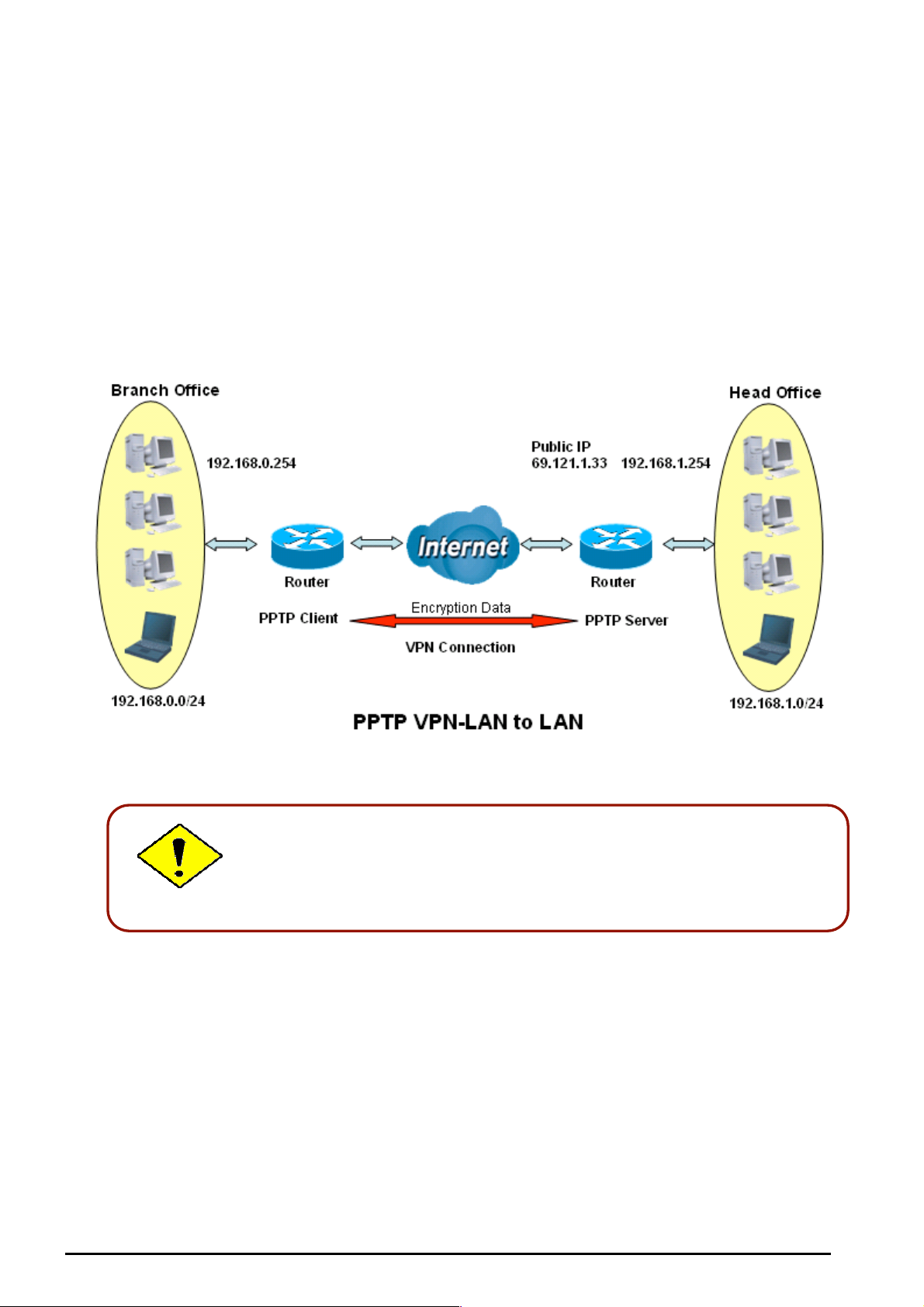
TW-EA510 version 4 ADSL2+, WLAN 802.11g, VPN, Firewall Router
Idle Time: Auto-disconnect the VPN connection when there is no activity on the connection for a
predetermined per iod of time. 0 means this c onnec t ion is always on.
Click Apply button to apply your changes.
Example: Configuring a PPTP LAN-to-LAN VPN Connection
The branc h of f ic e es t ablishes a PPTP V PN tunnel with head offic e t o c onnect t wo priv ate netw ork s over
the Internet . T he routers are installed in the hea d office an d branch off ic e ac c ordingly.
Both offic e LAN netwo rk s MUS T in different subnet with LAN to LAN
application.
75
Chapter 4: Configuration

TW-EA510 version 4 ADSL2+, WLAN 802.11g, VPN, Firewall Router
Configuring PPTP VPN in the Head Office
The IP addr es s 192.168.0.201 will be assigned to the rout er located in t he branch of f ice. Please make
sure this IP is not used in t he head offic e LAN.
Item
1 Connect ion Name HeadOffic e Given a name of PPTP connec t ion
Dial in Check Dia l in
Private IP Address
2
3
4
5
6 Idle Time 0
Assigned to
Dialing User
Peer Network IP 192.16 8.0.0 Branch office network
Netmask 255.255.255.0
Userna me usernam e
Password 123456
Auth.Type Chap(Auto)
Data Encryption Auto
Key Lengt h Auto
Mode stateful
Function Description
192.168. 0. 200 IP address assi gned to bra nc h of f ic e network
Input username & password t o aut henticat e branch
office net w ork
Keep as def ault value in most of t he c as es , PPTP
server & client will det ermine the v alue auto m at ic ally.
Refer to ma nual for details if you wa nt t o c hange the
setting.
The conn ec t ion will be disc onnected when there Is no
traffic in a pr edefined p eriod of time. I dle t ime 0 means
the connect ion is alway s on.
Chapter 4: Configuration
76

TW-EA510 version 4 ADSL2+, WLAN 802.11g, VPN, Firewall Router
Configuring PPTP VPN in the Branch Office
The IP address 69.1.121.30 is the Public IP address of the router located in head office. If you
registere d the DDNS (please refer to the DDNS section of this manu al), you can also use the do main
name instead of the I P address t o reach the rout er.
Item
1 Connect ion Name BranchOf f ic e Given a name of PPTP connec t ion
Dial out Check Dial out
2
Server IP Address
(or Domai n name )
Peer Network IP 192.16 8.0.0
3
Netmask 255.255.255.0
Userna me usernam e
4
Password 123456
Auth.Type Chap(Auto)
Data Encryption Auto
5
Key Lengt h Auto
Mode stateful
6 Idle Time 0
Function Description
69.121.1.33 IP address of the he ad of f ic e router (in W AN side)
Head office network
Input username & password t o aut henticat e branch
office net w ork
Keep as def ault value in most of t he c as es , PPTP
server & client will det ermine the v alue auto m at ic ally.
Refer to ma nual for details if you wa nt t o c hange the
setting.
The conn ec t ion will be disc onnected when there Is no
traffic in a pr edefined p eriod of time. I dle t ime 0 means
the connect ion is alway s on.
Chapter 4: Configuration
77

TW-EA510 version 4 ADSL2+, WLAN 802.11g, VPN, Firewall Router
QoS (Quality of Service)
QoS function helps you to control your network traffic for each applic ation from LAN (Ethernet and/or
Wireless) t o WA N (Int ernet ). It facilit ates y ou to cont rol t he diffe re nt qua lity an d spe ed of t hroug h p ut for
each applicati on when th e system is running with full loading of upstream.
Here are the items within the QoS section: Prioritization and Outbound / Inbound IP Throttling
(bandwidth management).
Prioritization
There are t hree priority s et t ings to be provided in the Router:
High
Normal (The default is normal pri orit y f or all of traf f ic without setting)
Low
And the balances of utilization f or each prio rit y are High (60 %), Normal (30%) and Lo w (10%).
Click Clear
You can click Clear to delete the existing Application.
Application: A user-defin e des c ription to identify this new policy/application.
Time Schedul e : Scheduling your pri orit ization policy.
Priority: The priorit y given to each policy/ application. Its default setting is set to High; you may adjust
this setting t o f it y our policy/a pplication.
Protocol: The name of sup ported protocol.
Source Port: The source port of pac k et s t o be monitored.
Chapter 4: Configuration
78

TW-EA510 version 4 ADSL2+, WLAN 802.11g, VPN, Firewall Router
Destination Port: T he destinat ion port of pac k et s to be monit ored.
Source IP A d dress Ra n ge: The source IP address or range of packets to be monitored.
Destination IP Address Ra n ge: The dest inat ion IP ad dress or range of pack et s t o be monitored.
DSCP Marking: Differ entiate d Services Code Point (DSCP), it is the first 6 bits in the ToS by te. DS CP
Marking allows users to classify traffic based on DSCP value and send packets to next Router. See
Table 4. Here is the DS C P Mapping T able:
Note: To be sure th e router(s) in t he back bones netw ork have the capability in executing and ch ecking the DSCP
through-out the QoS network.
Table 4: DSCP Mapping Table
DSCP Mapping Table
(Wireles s) ADS L Router Standard DSCP
Disabled None
Best Effort Best Effort (000000)
Premium Express F orwardin g (101110)
Gold service (L) Clas s 1, Gold (00101 0)
Gold service (M) Class 1, Silv er (001100)
Gold service (H) Class 1, Br onz e (001110)
Silver service (L) Class 2, Go ld (010010)
Silver service (M) Class 2, Silver (010100)
Silver service (H) Class 2, Bronze (010110)
Bronze se rv ic e (L) Class 3, Gold (011010)
Bronze se rv ic e (M) Class 3, Silver (011100)
Bronze se rv ic e (H) Clas s 3, Bronze (01 1110)
Chapter 4: Configuration
79

TW-EA510 version 4 ADSL2+, WLAN 802.11g, VPN, Firewall Router
Outbound IP Throttling (LAN to WAN)
IP Throttling allows you to limit the speed of IP traffic. The value entered will limit the speed of the
applicati on t hat you set t o t he s pecified v alue’s multiple of 32k bps.
Click Clear
Application: A user-defin e des c ription to identify this new policy/application.
Time Schedul e : Scheduling your pri orit ization policy. Refer to Time Sche dule for mo re information.
Protocol: The name of sup ported protocol.
Source Port: The source port of pac k et s t o be monitored.
Destination Port: T he destinat ion port of pac k et s to be monit ored.
Source IP A d dress Ra n ge: The source IP address or range of packets to be monitored.
Destination IP Address Ra n ge: The dest inat ion IP ad dress or range of pack et s t o be monitored.
Outbound Rate Limit: To limit the s peed of outb ound traff ic
You can click Clear to delete the existing Application.
Chapter 4: Configuration
80

TW-EA510 version 4 ADSL2+, WLAN 802.11g, VPN, Firewall Router
Inbound IP Throttling (WAN to LAN)
IP Throttling allows you to limit the speed of IP traffic. The value entered will limit the speed of the
applicati on t hat you set t o t he s pecified v alue’s multiple of 32k bps.
Click Clear
Application: A user-defin e des c ription to identify this new policy/application.
Time Schedul e : Scheduling your pri orit ization policy. Refer to Time Schedule for more informat ion.
Protocol: The name of sup ported protocol.
Source Port: The source port of pac k et s t o be monitored.
Destination Port: T he destinat ion port of pac k et s to be monit ored.
Source IP A d dress Ra n ge: The source IP address or range of packets to be monitored.
Destination IP Address Ra n ge: The dest inat ion IP ad dress or range of pack et s t o be monitored.
Inbound Rate Limit: To limit the s peed of for inb ound traffic.
You can click Clear to delete the existing Application.
Chapter 4: Configuration
81
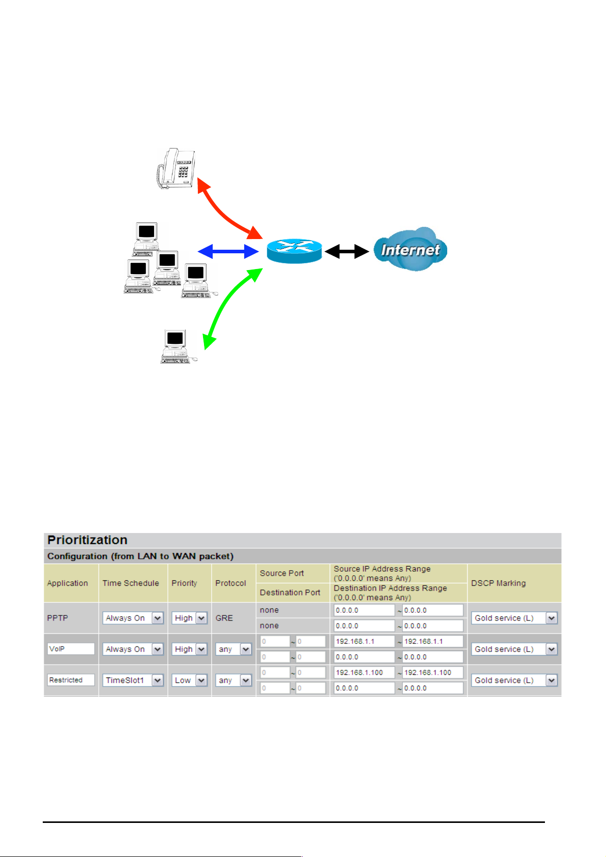
Example: QoS for your Network
Connection Diagram
VoIP
Normal PCs
TW-EA510 version 4 ADSL2+, WLAN 802.11g, VPN, Firewall Router
Information and Settings
Upstream: 92 8 kbps
Downstr eam: 8 Mbps
VoIP User : 192.168.0.1
Normal Users : 192. 168.0.2~192.168. 0.5
Restricted Us er: 192. 168. 0.1 00
Restricted PC
Chapter 4: Configuration
82

TW-EA510 version 4 ADSL2+, WLAN 802.11g, VPN, Firewall Router
Throughput
500
kbps
400
300
200
100
0
VoIP/VPN
HIGH
Others
NORMAL
Restricted
LOW
VoIP/VPN
HIGH
Others
NORMAL
Restricted
LOW
Mission-critical application
Mostly the VPN connection is mission-critical application for doing data exchange between head and
branch offic e.
The missi on-c ritical application must be sent out smoothly witho ut any dropping. Set priority as high level
for preventing any other applic at ions to saturate the bandwidth.
Voice application
Voice is latenc y-sensitiv e applicati on. Most VoI P devices are us e SIP protoc ol and the po rt number wil l
be assign ed by SIP modul e automatically . Better to use fix ed IP address for c atching VoIP pack ets as
high priority .
Above sett ings will help t o improve quality of y our VoIP serv ic e when traf f ic is f ull loading.
Restricted Application
Some of companies will setup F T P s erv er for customer do w nloading or home user sharing th eir f iles by
using FTP.
With abov e set tin gs that hel p to l i mit util izatio n of upst rea m of FT P. Time s ch edule also he lp y ou to only
limit utilization at dayt ime.
Chapter 4: Configuration
83

TW-EA510 version 4 ADSL2+, WLAN 802.11g, VPN, Firewall Router
Advanced setting by using IP throttling
With IP thrott ling you ca n specify more deta il for alloc ating ba ndwidth; even the ap plicat ions are lo cated
in the same level.
Upstream: 92 8kbps (29* 32k bps)
Mission-c rit ic al Application: 192kbps (6*32kbps
Voice Application: 128kbps (4* 32kbps)
Restricted Application: 160kbps (5*32kbps)
Other Applications : 448kbps (14*32kbps)
6+4+14+ 5=29, 29*3 2k bps=92 8k bps
Someti me your c usto mers or frien ds may uploa d their f iles to y our F TP serv er and t hat will satur ate you r
downstrea m band widt h. The sett ings bel ow help you to limit band widt h for the restrict ed applic ation.
Chapter 4: Configuration
84
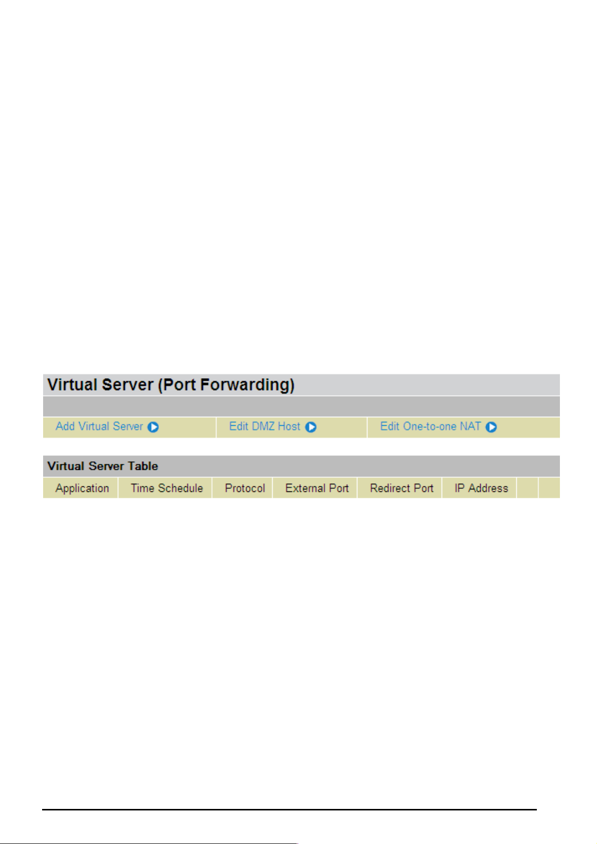
TW-EA510 version 4 ADSL2+, WLAN 802.11g, VPN, Firewall Router
Virtual Server (“Port Forwarding”)
In TCP/IP and UDP networks a port is a 16-bit number used to identify which application program
(usually a serv er) inc oming c onnect ions sho uld b e deliver ed to. So me ports hav e nu mbers that are preassigned to them by the IA NA (the Inter net Assig ned Num bers Autho rity), and t hese ar e referred to as
“well-kno w n ports”. Se rv ers f ollow the w ell-known port assi gnments so c lients can l oc at e t hem.
If you wish to run a server on your network that can be accessed from the WAN (i.e. from other
machines on the Internet that are outside your local network), or any application that can accept
incoming c onnect ions ( e.g. Peer -to-pee r/P2P s oftw are such as insta nt mess aging a pplicat ions a nd P2P
file-shari ng applications) an d are using N AT (Network Address T ranslation), t hen you will us ually nee d t o
configur e your router to forward thes e incoming connect ion attempts using sp ecific ports to the PC on
your net work run ning the applicatio n. You will also need to use p ort forwarding if you want to host an
online game serv er.
The reaso n f or t his is t hat when us ing NA T, y our publicly accessible IP add res s will be used by and point
to your router, which then needs to deliver all traffic to the private IP addresses used by your PCs.
Please se e t he WAN configuration sec t ion of this manual for more infor mation on NA T.
The devic e can be confi gured as a virtu al serv er so that remot e users acces sing serv ices s uch as Web
or FTP services via the public ( WAN) IP address can be auto matically re directed to local s ervers in t he
LAN network. Depending on the requested service (TCP/UDP port number), the device redirects the
external service request to the appropriate serve r within the LA N network
Chapter 4: Configuration
85

TW-EA510 version 4 ADSL2+, WLAN 802.11g, VPN, Firewall Router
Add Virtu al Server
Because NAT can act as a “natural” Internet firewall, your router protects your network from being
accesse d by outsi de users w hen us ing NA T, as all incom ing co nnec tio n attem pts will poi nt to your route r
unless you s pecifically c reate Virtual Serv er entries t o f orw ard t hose ports t o a PC on your network.
When you r router ne eds t o allow outs ide users t o access int ernal servers, e.g. a web serv er, FTP server,
Email server or game serv er, t he rout er c an act as a “virt ual server”. You ca n s et up a loc al server with a
specific port number for the service to use, e.g. web/ HTTP (port 80), FTP (port 21), Telnet (port 23),
SMTP (po rt 25), o r P OP3 (p ort 1 10), Whe n an i nc omin g acces s r eques t to t he rout er f or a s pecifi ed port
is received, it wi ll be forwarded to the c orrespond ing intern al s erver.
Time Schedule: A self-defined time period to enable your virtual server. You may specify a time
schedule or Always on for the usage of this Virtual Server Entry. For set up and detail, r efer to Time
Schedule section
Application: Users-define description to identify this entry or click
predefined rules.
: 20 predefined rules are available. Click the Radio button t o select the rule; Application,
Protocol a nd External/Redirec t Ports will be filled after t he s election.
Protocol: It is the support ed protocol for the v irtual server. In additi on to specifying t he port number to
be used, you will also need to specify the protocol used. The protocol used is determined by the
particular ap plicati on. Most applic atio ns will use TC P or UDP.
External Port: The P ort number o n t he Remote/WAN sid e us ed when accessin g t he v irt ual server.
Redirect P ort: The Po rt number used by the Loc al server in t he LAN network.
to select existing
86
Chapter 4: Configuration

TW-EA510 version 4 ADSL2+, WLAN 802.11g, VPN, Firewall Router
Internal IP Address: The private IP in the LAN network, which will be providing the virtual server
applicati on.
IP address and MA C from this list.
List all exist ing PCs con necting to the net work. You may assign a P C with
Example:
If you like to remote ac c essin g your Rout er thro ugh t he Web/ HT TP at all t ime, you would n ee d to en able
port numbe r 80 (Web/HTTP) an d map to Router’s IP Addres s. Then all incoming HT TP requests fro m
you (Remot e si de) wi ll be fo rwar ded t o the Route r with IP a ddres s of 1 92.1 68.0. 25 4. Sinc e port nu mber
80 has already bee n pr edef ined, next t o the Application click Help er. A lis t of pre defin ed r ules win dow
will pop and s elect HTTP_Sever.
Application: HTTP_Sever
Time Schedule: Al ways On
Protocol: tcp
External P ort : 80-80
Redirect Port: 80-80
IP Address: 192.168.0.254
Edit: Click it t o edit t his v irt ual server application.
Delete: Click it to delete t his v irt ual server application.
Using port forwarding does have security implications, as outside users will be able to
connect to PCs on your ne twor k. For t his reason y ou are advised to us e specific Virtua l
Server entries just for the ports your application requires, instead of using DMZ. As
doing so will result in all connections from the WAN attempt to access to your public IP
of the DMZ PC specified.
If you have disabled the NAT option in the WAN-ISP section, the Virtual Server function
will hence be invalid.
If the DHCP server option is enabled, you have to be very careful in assigning the IP
addresses of the virtual servers in order to avoid conflicts. The easiest way of configuring
Attention
Virtual Servers is to manually assign static IP address to each virtual server PC, with an
address that does not fall into the range of IP ad dresses that are to be issued by the DHCP
server. You can configure the virtual server IP address manually, but it must still be in the
same subnet as the router.
Chapter 4: Configuration
87

TW-EA510 version 4 ADSL2+, WLAN 802.11g, VPN, Firewall Router
Edit DMZ Host
The DMZ Host is a loca l co mput er ex pos ed t o the Intern et. Whe n sett ing a p artic ular i nter nal IP ad dres s
as the DMZ Host , all incomi ng packet s will be che cked by the Fir ewall an d NAT algorit hms the n passed
to the DM Z host , when a pack et receiv ed d oes n ot use a port numb er used by any other Virtual Server
entries.
Cautious: This Local computer exposing to the Internet may face varies of security risks.
Disabled: As s et in default s et t ing, it dis ables the DMZ function.
Enabled: It activates your DMZ function.
Internal I P Address: G ive a s tatic IP address to the DM Z Host w hen Enabled radio butt on is chec k ed.
Be aware t hat t his I P will be expos ed to the W AN/Internet .
Listed all ex is t ing PCs co nnecting to the network . You may assign a PC with IP address
and MAC from this list .
Select the Apply button to apply y our chan ges .
Chapter 4: Configuration
88

TW-EA510 version 4 ADSL2+, WLAN 802.11g, VPN, Firewall Router
Edit One-to-One N A T ( N etwork A d dress Tran sl ati o n )
One-to-One NAT m aps a specific private/l oc al I P address t o a global/p ublic IP address.
If you have m ult iple public/WAN IP a ddresses from you ISP, y ou are eligible for On e-t o-One NA T to
utilize thes e I P addresses .
NAT Type: Select desir ed NAT type. As s et in default s et t ing, it disables t he One-to- One NAT fu nc t ion.
Global IP A d dress:
Subnet: The subnet of the public/WAN IP ad dress given by your I SP. If your ISP has provid ed
this inform at ion, you m ay ins ert it here. Otherwise, use IP Range method.
IP Range: The IP address range of your public/WAN IP addresses. For example, IP:
192.168. 0. 1, end IP: 192. 168.0.10
Select the Apply button to apply y our chan ges .
Check
to create a new One-to-One NA T rul e:
Chapter 4: Configuration
89
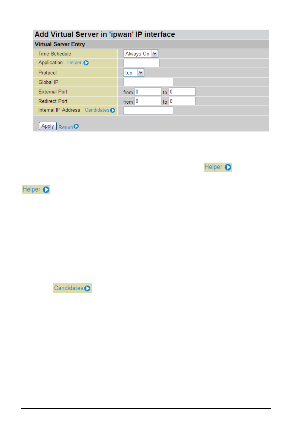
TW-EA510 version 4 ADSL2+, WLAN 802.11g, VPN, Firewall Router
Time Schedule: A self-defined time period to enable your virtual server. You may specify a time
schedule or Always on for the usage of this Virtual Server Entry. For set up and detail, r efer to Time
Schedule section
Application: Users-defined description to identify this entry or click
to select existing
predefined rules.
: 20 predefined rules are available. Click the Radio button t o select the rule; Application,
Protocol a nd External/Redirec t Ports will be filled after t he s election.
Protocol: It is the support ed protocol for the v irtual server. In additi on to specifying t he port number to
be used, you will also need to specify the protocol used. The protocol used is determined by the
particular ap plicati on. Most applic atio ns will use TC P or UDP;
Global IP: Define a public / WAN IP a ddress for this Application to use. This Global IP address must be
defined in t he Global I P A d dress.
External Port: The P ort number o n t he Remote/WAN sid e us ed when accessin g t he v irt ual server.
Redirect P ort: The Po rt number used by the Loc al server in t he LAN network.
Internal IP Addres s: The privat e IP in the LAN network, w hic h will be providing the virtual serv er
applicati on.
List all exist ing PCs co nnecting t o t he network . You may assign a PC with
IP address and MA C from this list.
Select the Apply button to apply y our chan ges .
Chapter 4: Configuration
90

TW-EA510 version 4 ADSL2+, WLAN 802.11g, VPN, Firewall Router
Example: List of some well-known and registered port numbers.
The Internet Assigne d Num bers Autho rity (IA NA) is the c entral coord inator f or the assi gnment of unique
paramet er values for Inter net protocols. Port numbers ra nge from 0 to 65535, but only ports numb ers 0
to 1023 ar e reserved for privileged s ervices and are designate d as “well-kno wn ports” (Pl ease refer t o
Table 5). The re gistered p orts are num bered fro m 1024 throug h 49151. The r emaining ports, refe rred
to as dynam ic or private ports, are n umbered from 49152 through 65535.
For further informati on, please see IANA’s w ebs it e at: http://www.iana.org/assignments/port-numbers
For help on determining which private port numbers are used by com m on applications on this list, please
see the FAQs (Freque nt ly As k ed Questions) at: http://www.TeleWell.com
Table 5: Well -known and regi stered Ports
Port Number
20 TCP FTP Data
21 TCP FTP Control
22 TCP & UDP SSH Remote Login Protocol
23 TCP Telnet
25 TCP SMTP (Simple Mail Transfer Protocol)
53 TCP & UDP D N S (Domain Name Serv er)
69 UDP TFTP (Trivial File Transfer Protoc ol)
80 TCP World Wid e Web HT TP
110 TCP POP3 (Post Office Protocol Version 3)
119 TCP NEWS (Network News Transfer Protocol)
123 UDP NTP (Network Time Protocol)
161 TCP SNMP
443 TCP & UDP HTTPS
1503 TCP T.120
1720 TCP H.323
4000 TCP ICQ
7070 UDP RealAudio
Protocol Description
Chapter 4: Configuration
91

TW-EA510 version 4 ADSL2+, WLAN 802.11g, VPN, Firewall Router
Time Schedule
The Time Schedule supports up to 16 time slots which helps you to manage your Internet connection. In
each time profile, you may schedul e specific day (s) i.e. Mond ay through Sunday to res trict or allo wing
the usage of t he I nt ernet by us ers or applications.
This Time Sc he dule c orrel ates clos ely with ro uter ’s time, sinc e ro uter d oes n ot hav e a re al ti me cl oc k on
board; it us es the Simpl e Network Time Protocol (SNTP) to get the current ti me from an S NTP server
from the Internet. Refer to Time Zone for details. You router time should correspond with your local
time. If t he t ime is not set correc t ly , y our Time Sc hedule will n ot f unc t ion properly .
Chapter 4: Configuration
92

TW-EA510 version 4 ADSL2+, WLAN 802.11g, VPN, Firewall Router
Configur a ti o n of Ti m e Sc he d ul e
Edit a Time Sl o t
1. C hoose any Ti m e Slot (ID 1 to I D 16) t o edit, click Edit.
Click Edit
Note: Watch it care fully, the days you have s elected will present in capital let ter. Lower cas e letter show s the
day(s) is not selected, and no rule will apply on this day(s).
2. A det ailed sett ing of this Tim e Slot will be s hown.
ID: This is the i ndex of the time slot.
Name: A user-defi ne descript ion to identif y t his t im e portfolio.
Day: The default is set from Mon day throu gh Friday. You may specify t he days for the s chedule to be
applied.
Start Time: The d ef ault is set at 8: 00 AM. You m ay s pec if y t he s t art t ime of the sc hedule.
End Time: The def ault is set at 18: 00 (6:00PM). You may s pecify the end time of the schedule.
Select the Apply button to apply y our chan ges .
Delete a Ti me Slot
Click Clear to delet e t he ex is t ing Time profile, i.e. erase the Day and bac k t o default s et t ing of Start Time
/ End Time.
Chapter 4: Configuration
93

TW-EA510 version 4 ADSL2+, WLAN 802.11g, VPN, Firewall Router
Advanced
Configur at ion options within the Advanced sect ion are fo r us ers who wish to take a dv antage of t he
more adv anc ed features of t he router. Users who do not un ders t and the features sh ould not att empt to
reconfig ure t heir route r, unless advised to do so by support s t af f .
There are fou r ite ms within t he Advanced section: Static Route, Dy namic DNS, Chec k Email , Device
Management, IGMP, VLAN Bridge and WAN IP Ale rt .
Static Route
Click on Rout i n g Ta ble and t hen choose Create R oute add a routi ng t able.
Destination: This is t he destinat ion subnet I P address.
Netmask: Subnet mas k of t he destinati on I P addres s es based on a bove desti nat ion subn et I P.
Gateway: This is the gateway I P address t o w hic h packets are to be forw arded.
Interface: Select t he int erface th rough which packet s are t o be forwarded.
Cost: This is t he same m eaning as Ho p. T his s hould us ually be left at 1.
Chapter 4: Configuration
94
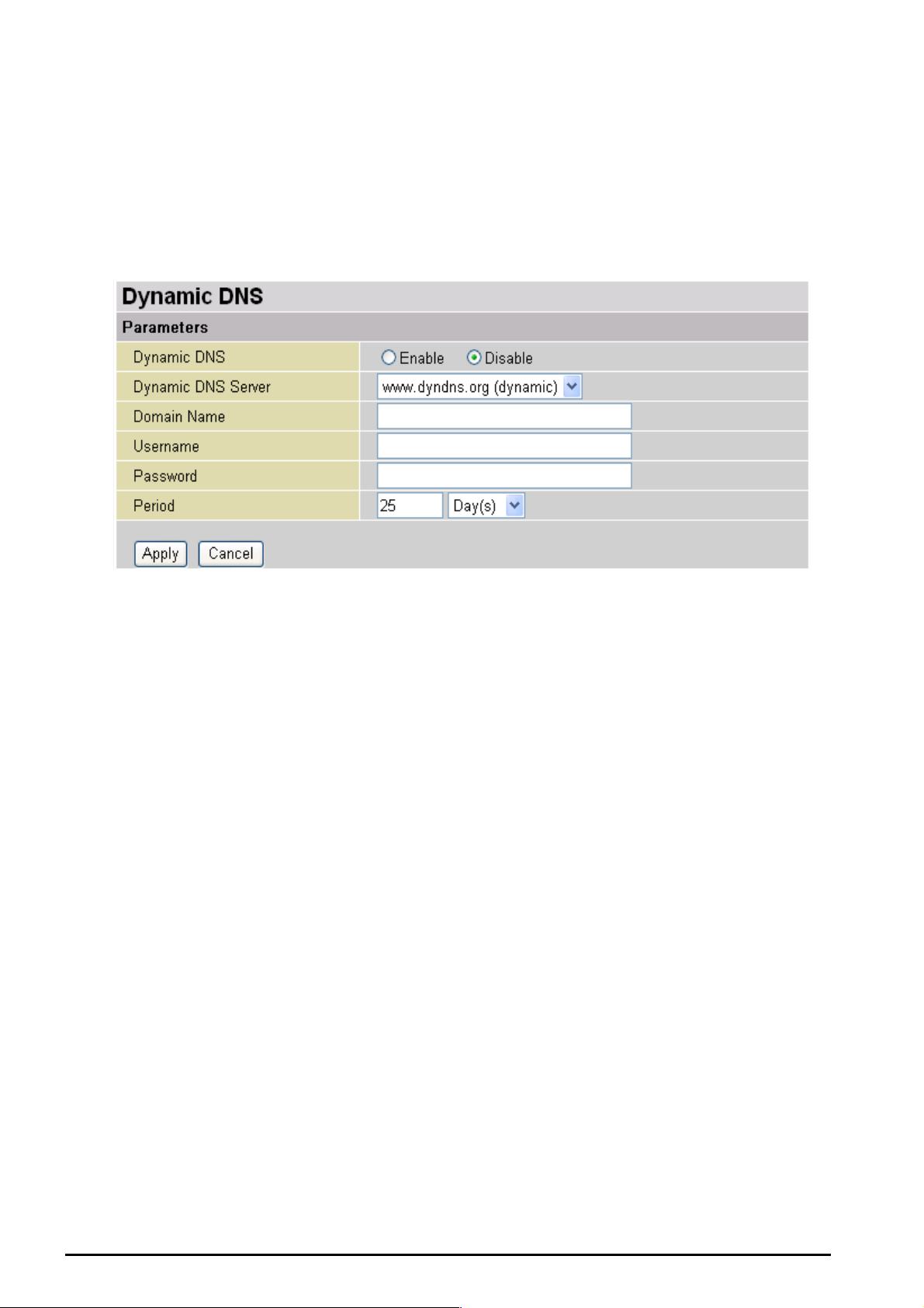
TW-EA510 version 4 ADSL2+, WLAN 802.11g, VPN, Firewall Router
Dynamic DNS
The Dynamic DNS function allows you to alias a dynamic IP address to a static hostname, allowing
users whose ISP does not assign them a static IP address to use a domain name. This is especially
useful for hos ting serv ers via yo ur ADSL con necti on, so that any one wish ing to c onnect t o you may use
your domain name, rather than having to use your dynamic IP address, which changes from time to
time. This dy namic IP address is t he WAN IP addres s of the router, which is as signed to you by your
ISP.
You will first need to register and establish an account with the Dynamic DNS provider using their
website, for example http:// w w w.dyndns. org/
There are more than 5 DDNS services supported.
Disable: Check t o disable the Dynam ic D N S f unction.
Enable: Check to enable the Dynamic DNS function. The following fields will be activated an d
required:
Dynamic D NS Server : Selec t t he DDNS serv ic e you have es t ablishe d an account w it h.
Domain Name, Username and Pass word: Enter y our registered domain name and your usern ame and
password f or t his service.
Period: Set the time period between updates, for the Router to exchange information with the DDNS
server. In addition to updating periodic ally as p er your set tings, the r outer wil l perfor m an update when
your dyna m ic I P address c hanges.
Chapter 4: Configuration
95

TW-EA510 version 4 ADSL2+, WLAN 802.11g, VPN, Firewall Router
Check E mai l
This function allows you to have the router chec k your PO P3 mailbox f or new E m ail messa ges . The Mail
LED on your route r will light whe n it detects new mes sag es wait ing for downl oad. You may als o v iew the
status of this function using the Status – Email Checking section of the web interface, which also
provides details on the number of new messages waiting. See the Status section of this manual for
more infor m at ion.
Check E mai l :
Disable: Check t o disable the router’s Email checking fu nc t ion.
Enable: Check to enable the routers Emailing checking function. The following fields will be
activated an d required:
Account Name: Enter the name (login) of the POP3 account you wish to check.. Normally, it is th e text
in your ema il address before the "@" s ymbol. If y ou have trouble with it, please cont ac t y our I SP.
Password: Enter t he account ’s pas sword.
POP3 Mail Ser ver: Enter your (POP) mail server name. You I nternet Serv ice Provi der (ISP) or n etwork
administrator will be able to supply you with t his.
Period: Enter the v alue in minutes betwe en periodic mail checks.
Automatically dial-out for checking emails: When the function is enabled, your ADSL router will
connect t o your ISP a uto mat ically t o check em ails if your I nternet c onnec ti on drop pe d. Ple ase b e carefu l
when usin g t his f eature if yo ur ADSL serv ic e is c harged by time onlin e.
Chapter 4: Configuration
96

TW-EA510 version 4 ADSL2+, WLAN 802.11g, VPN, Firewall Router
Device Man age men t
The Device Management advanced configuration settings allow you to control your router’s security
options an d device m onit oring features.
Embedded Web Server ( 2 Management IP Accounts)
HTTP Port: This is the port number the router’s embedd ed web serv er (for web-based configuration) will
use. The def ault valu e is the sta ndard H TTP port, 80. Users may specify an alternativ e if, for exa mple,
they are ru nning a web server on a PC within their LAN.
Mana ge me nt IP Ad dre ss: You m ay s pec if y an IP addr es s allowed to logon and ac c es s t he router’s web
server. Set ting the I P addres s to 0.0.0. 0 will dis able IP ad dress restrictio ns, all owing use rs to log in fro m
any IP addr es s .
Expire to auto-logout: Specify a time frame for the system to auto-logout the user’s configuration
session.
Chapter 4: Configuration
97

TW-EA510 version 4 ADSL2+, WLAN 802.11g, VPN, Firewall Router
For Example: User A changes HTTP port number to 100, specifies their own IP address of
192.168.0.55, an d s et s t he logout tim e t o be 100 seconds. T he router will only allo w User A acces s f rom
the IP address 192.168.0.55 to logo n to the Web GUI by typing: http://192.168.0.254:100
browser. Af t er 100 seconds, the d ev ic e will automatically logout User A.
Universal Plug and Play (UPnP)
UPnP offers peer-to-peer network connectivity for PCs and other network devices, along with control
and data transfer between devices. UPnP offers many advantages for users running NAT routers
through UPnP NAT Traversal, and on supported systems makes tasks such as port forwarding much
easier by lett ing the applicat ion control the r equired settin gs, removing th e need for the use r to control
advance d c onf iguratio n of t heir device.
Both the user’s Operating System and the relevant application must support UPnP in addition to the
router. Windows XP and Windows Me natively support UPnP (when the c omponent is installed), and
Windows 98 users may install the Internet Connection Sharing client from Windows XP in order to
support UP nP. Windo ws 2000 does not s u pport UPnP.
Disable: Check t o disable the router’s UPnP functionality.
in their we b
Enable: Check to en able the router’s UPnP f unctionality.
UPnP Port: Its default setting is 2800. It is highly recomm ended for users to use this port value. I f t his
value conflic t s with other p ort s already b eing used y ou may wish to change th e port.
SNMP Access Control
Simple Netw ork Mana ge ment Prot oc ol.
SNMP V1 and V2:
Read Community: Specify a name to b e identif ied as the R ead Co mmunity, a nd an IP a ddress. This
community string will be checked against the string entered in the configuration file. Once the string
name is mat c hed, user obtains this I P address will be able to v iew the dat a.
Write Community: Specify a name to be identified as the Write Community, an d an IP addres s. This
community string will be checked against the string entered in the configuration file. Once the string
name is mat c hed, users f rom this IP address will b e able to view a nd modify t he data.
Trap Community: Specify a name t o be identified as the Tr ap Community, and an IP address. Th is
community string will be checked against the string entered in the configuration file. Once the string
name is mat c hed, users f rom this IP address will b e s ent SNMP Tra ps .
SNMP V3:
( Software o n a PC within t he LAN is require d in order to utiliz e this function) –
Specify a n a me an d pas s word fo r a uthe nticat ion. An d d efine t he acces s ri ght fro m id entif ied I P ad d ress.
Once the a uthenticatio n has succ eeded, users from this I P address wil l be able to vie w and modif y the
data.
Chapter 4: Configuration
98

TW-EA510 version 4 ADSL2+, WLAN 802.11g, VPN, Firewall Router
SNMP Versi on: SN M Pv 2c an d S NMP v 3
SNMPv2c is the combination of the enhanced protocol features of SNMPv2 without the SNMPv2
security. T he "c" comes fr om the fact that SNMPv2c uses t he SNMPv1 co mmunity st ring paradigm fo r
"security ", but is wi dely acce pt ed as t he SNMPv 2 standard.
SNMPv3 is a s t rong authe nt ic at ion mechanism, a ut horization with fine gr anularity f or remote mo nit oring.
Traps supported: C old Start, Authenticat ion Failur e.
The follo wi ng MIBs are supporte d:
From RFC 1213 (MIB-II ):
System group
Interfaces group
Address Translation group
IP group
ICMP group
TCP group
UDP group
EGP (not applicable)
Transmission
SNMP group
From RFC 1650 (Eth erLike- MIB):
dot3Stats
From RFC 1493 (Bri d ge MIB):
dot1dBase group
dot1dTp group
dot1dStp group (if conf igured as spanning t ree)
Fro m RFC 1 471 (PPP /LCP MIB) :
pppLink group
pppLqr group
Chapter 4: Configuration
99
 Loading...