

TeleWell TW-5614UL User Manual
TeleWell TW-5614UL V.92 & V.90 Modem
User’s Manual

2
Table of Contents
1. Introduction....................................................... .. ....................................................... ..... 3
2. Features............................... ... ..................................................... ... ................................. 3
3. The Appearance of External Modem..............................................................................4
3.1 External Modem Front Panel................................................................................ 4
3.2 External Modem Back Panel................................................................................5
4. Installing The External Modem...................................................................................... 6
4.1 Checking Your Components ........................................................... ...................... 6
4.2 What Else You Need................................. ........ ........... ........... ........ .......... ........ ....6
4.3 Connecting To The Telephone Line...................................................................... 6
4.4 Connecting T o You Telephone Set.................................... ........ ........... ........... ......6
4.5 Verifying Your Connection............................... ........... ........ ........... .......... ........ ....7
4.6 Connecting Microphone And Speaker.................................................................. 7
4.7 Configuring External Modem With W indows 95/98/ME/2000/NT4.0................ 8
4.8 T i ps On Configuring Your Communication Software........................................17
5. Executing Commands...................................................................................................18
6. S-Registers.................................................................................................. ... ............... 20
6.1 Reading An S Register Value..............................................................................20
6.2 Changing An S Register Value............................................................................ 20
6.3 S Register Definitions......................................................................................... 20
7. Response Sets............................ .. ...... ..... ... ..... ..... ... ..... ... ..... ...... .. ...... ..... ... ..... ..... ... ..... ..22
8. Specifications................. ...............................................................................................25
Appendix A-1 FCC Notice...................................... ................................ ..........................26
Appendix A-2 FCC Requirement............................ ................................ ..........................27
Appendix A-3 CE Mark Declaration.............................. ................................ ..................28
Appendix B: AT Command...............................................................................................29

3
1. Introduction
Congratulations on purchasing a state-of-the-art External Modem! Your External
Modem incorporates the latest technological advancement for you to
electronically communicate with other computers, information networks, fax
machines or other External Modems. It embraces most of the industry and
commercially popular standards to ensure compatibility with most equipment and
application programs. The voice capability renders a wide range of application
possibilities from a simple telephone-answering device to a sophisticated
voice-mail system. The optional SVD feature allows you to talk and transmit data
at the same time.
2. Features
1. Simultaneous Voice and Data
2. 56Kbps download speed from Internet
3. ITU-V.92 , V90 and K56Flex Dual Standards
4. Quick Connect
5. Modem-on-Hold
6. Call Waiting
7. Telephone Answering Machine (TAM) and Voice Mail Operations
8. Built-in Caller ID
9. 16550/A Compatible Enhanced UART for Sustained DTE Speed of 230.000
bps or 115,200bps
4
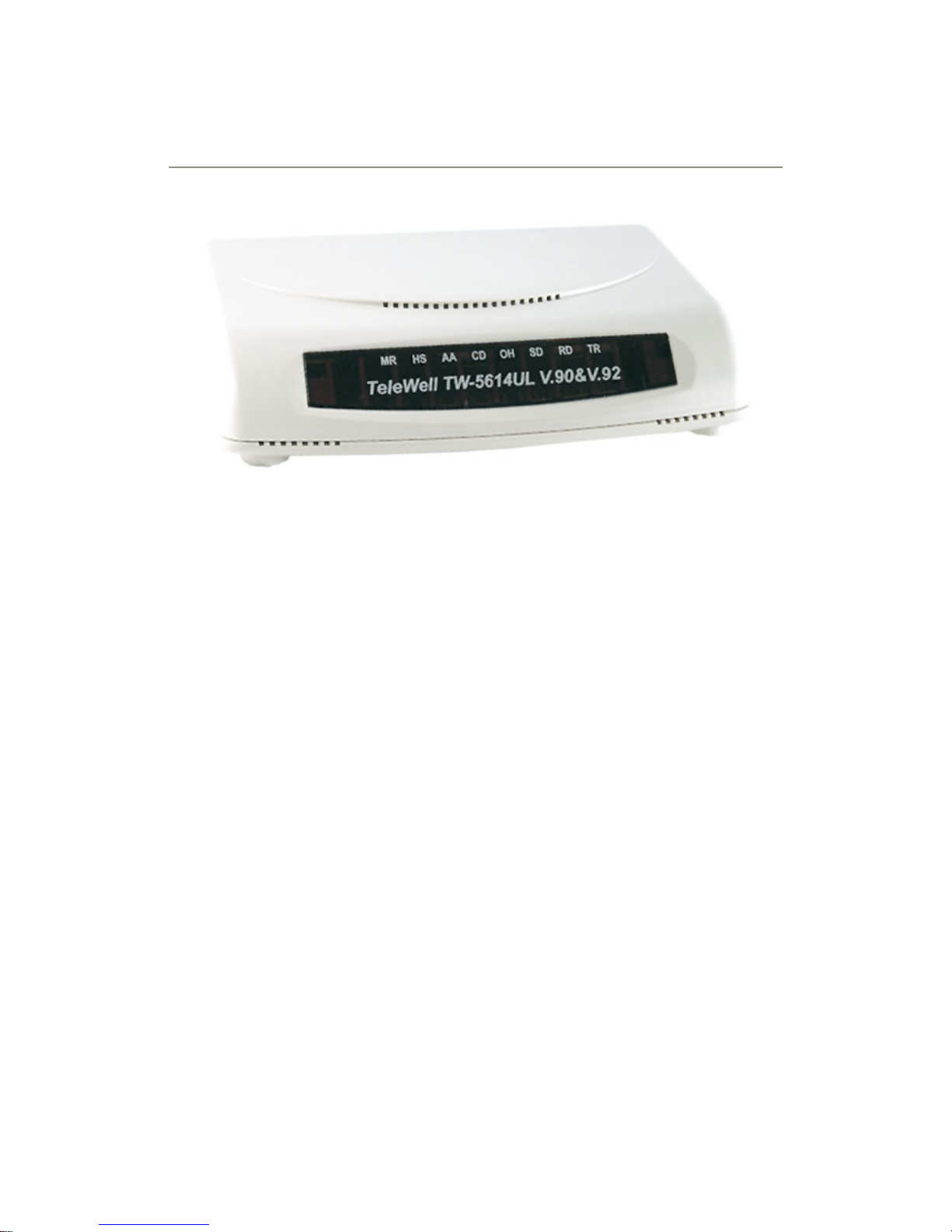
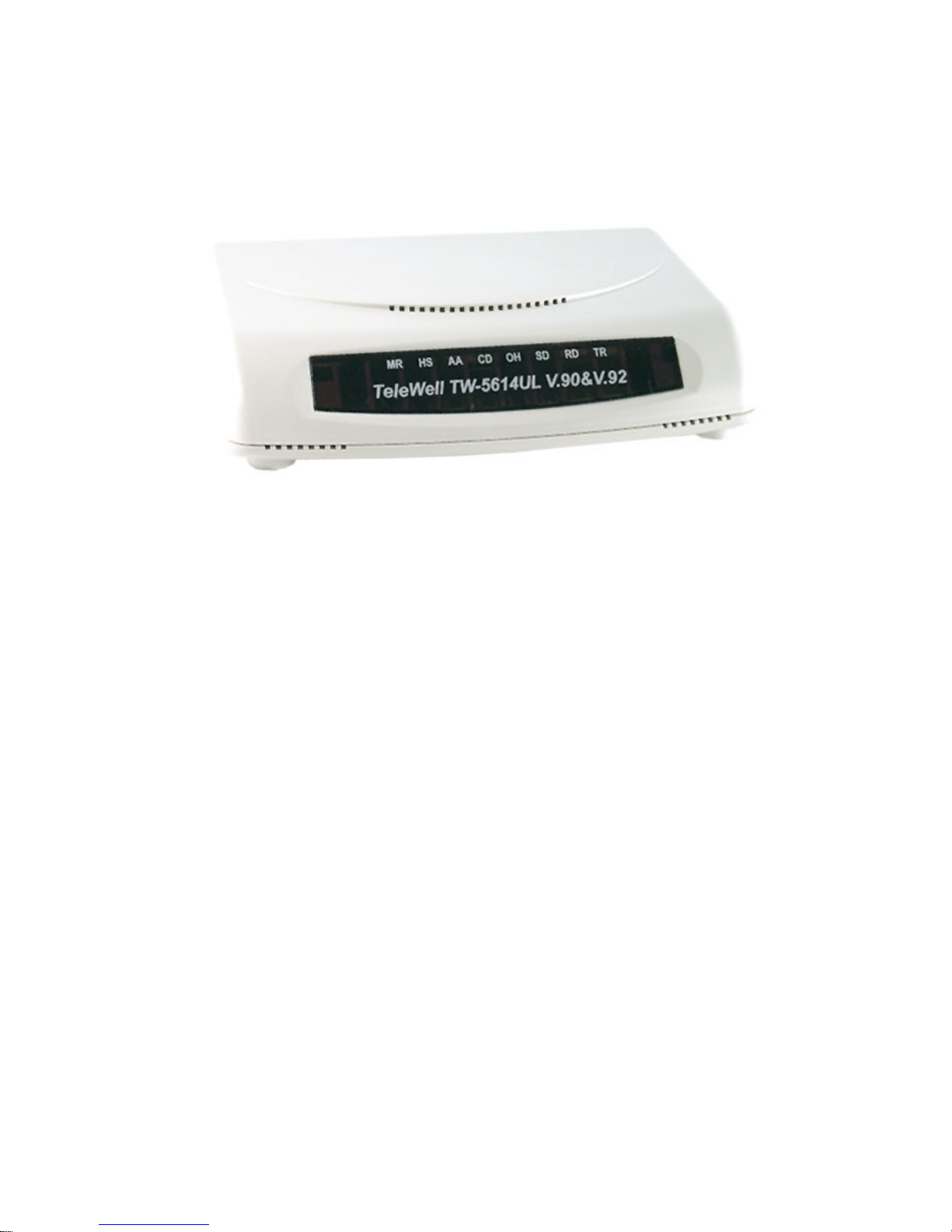
3. The Appearance of External Modem
3.1 External Modem Front Panel
LED Character Indicators
LED DESCRIPTION
MR Modem Ready Lights when power is applied to the modem. Flashes when
the modem is in test mode
HS High Speed In Command mode, lights when DTE-to-modem speed is 4,800
bps or above.
AA Auto Answer Lights when the modem is in auto-Answer mode. Flashes
when ring signal is received.
CD Carrier Detect Lights when carrier signal is received from remote modem.
OH Off-Hook Lights when the modem picks up or answer the telephone line.
SD Send Data Flashes when the local DTE transmits data to the modem.
RD Receive Data Flashes when the local DTE receives data from the modem.
TR Terminal Ready Lights when the modem receives the DTR signal from the
local DTE.
5
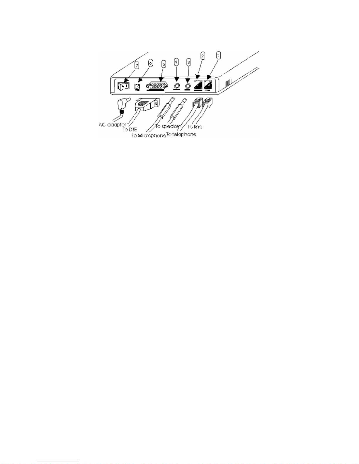
3.2 External Modem Back Panel
LINE Line RJ-11 jack
PHONE Teleph one RJ-11 jack
SPK Speaker mini-phone jack
MIC Microphone mini-phone jack
SERIAL PORT Serial DB-9 female connector
AC AC jack
Power switch Power on/off

6
4. Installing The External Modem
4.1 Checking Your Components
Unpack your External Modem and make sure you have the following items:
1. The External Modem.
2. A RS232C cable to connect your fax/modem to the serial port of Computer
3. A modular telephone cable to connect your External Modem to the telephone
line.
4. A Power adapter.
5. Communication software (included driver and manual)
When you open your package, make sure all of the above items are included and
not damaged. If you see that any components are damaged, please notify your
dealer immediately.
4.2 What Else You Need
To complete your data communication system, you will need the following items:
1. Other communication software, if needed.
2. An active telephone line and telephone set (if you need to use a
telephone with your modem).
4.3 Connecting To The Telephone Line
Use the following procedure to connect your External Modem to the telephone
line:
1. Locate an available RJ-11 modular jack telephone outlet.
2. Take one end of the modular cord supplied with the External Modem and plug
it into the LINE modular jack on the back of the External Modem.
3. Plug the other end of the modular cord into the modular jack on the wall outlet,
as you would any modular telephone.
4.4 Connecting To You Telephone Set
Your External Modem also conveniently provides a second modular jack that lets
you connect your telephone to the same telephone line that the External Modem
is using. This lets you manually dial data calls or make voice calls when you are
not using your External Modem. Also if you do not have speaker phone and
microphone, handset of telephone set can function as an input/output device for
voice to verify the connection.
Use the following procedure to connect your telephone to your External Modem:
1. Connect the telephone's modular cord into the PHONE jack on the back of
your External Modem.
2. Lift your telephone's handset and listen for a dial tone.

7
4.5 Verifying Your Connection
Start a communication program and place the computer into terminal mode. Refer
to your computer manual to find out the appropriate command to do so.
Then use the following procedure to verify your installation:
1. Type
AT[Enter]
If your system is operating properly, your External Modem sends an
OK response to your screen and waits for your next command.
2. Use your communication software to prepare your computer to dial
a call. Then type
ATDx phone number[Enter]
where x is equal to T for touch-tone or P for pulse dialing. The
phone number is your telephone number.
For example, if your External Modem is connected to the telephone
line 555-2121 and touch-tone dialing is supported in your area, type
ATDT 5552121[Enter].
3. You should hear the busy signal and receive a BUSY response
because the External Modem is calling itself.
4.6 Connecting Microphone And Speaker
You could either use a handset connected to the External Modem, or
connect a microphone and a speaker for voice recording and playback.
NOTE:
Any commercially available microphone is usable.
For the speaker, any 8 ohm speaker rated around 1Watt can be driven
directly by the audio output. An amplifier is required if you need a
higher output volume.
1. Connect the microphone to the mini-phone jack marked MIC.
2. Connect the speaker to the mini-phone jack marked SPK.
8
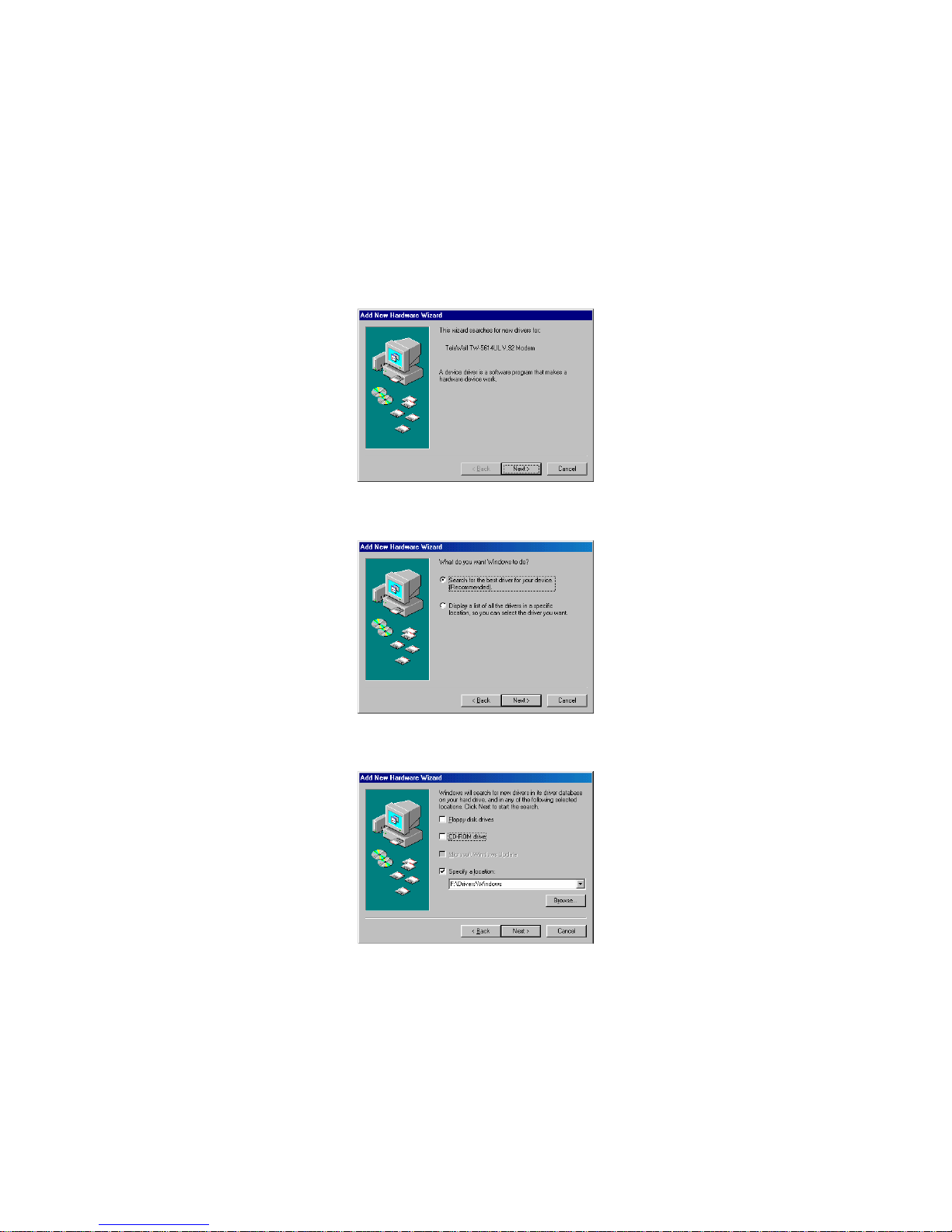
4.7 Configuring External Modem With Windows 95/98/ME/2000/NT4.0
Windows 95/98:
Configuring external modem in Windows 95 is similar to Windows 98. Please refer
to the installation below.
1. Restart the computer after connecting the modem to PC. When Windows
detects the modem, the message "This wizard searches for new drives for:
TeleWell TW-5614UL V.92 Modem" is displayed. Click Next.
2. To search for the best drivers for your device, click Next.
3. Specify the location: F:\Drivers\Windows. (F is your CD-ROM.) Click Next.
9
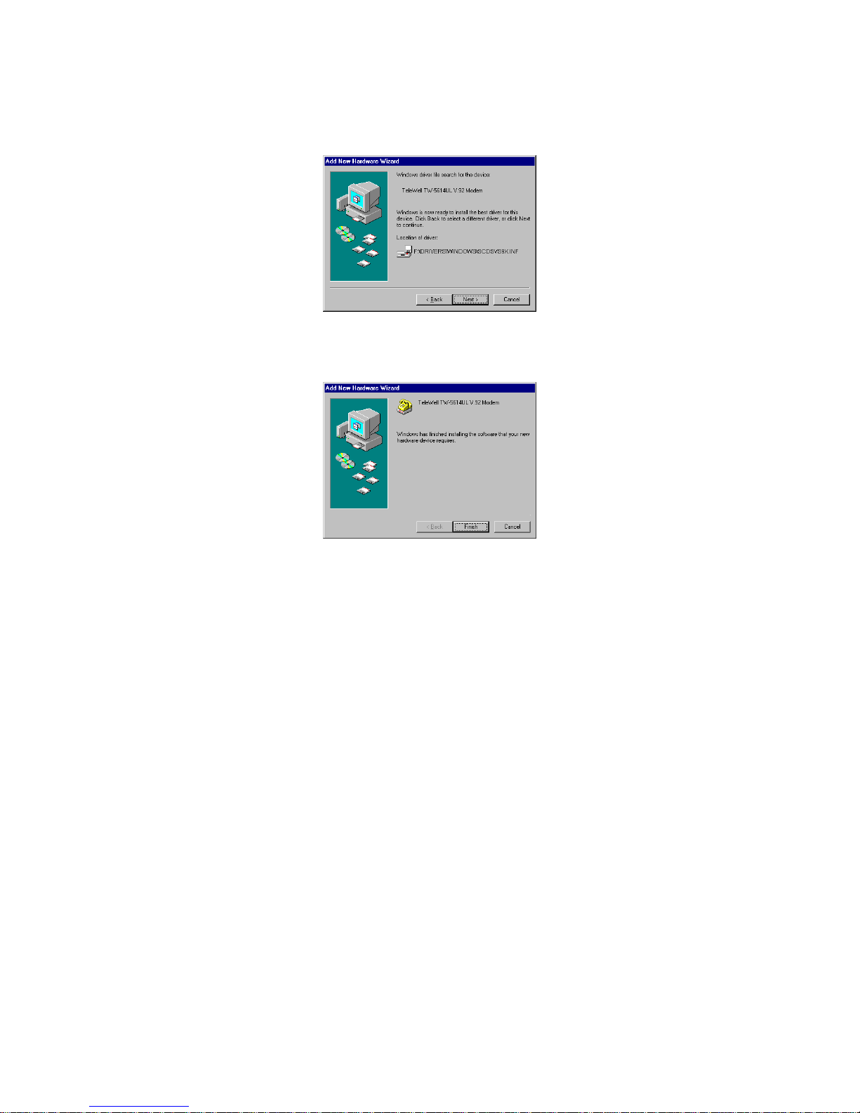
4. Windows will show the message ”Windows driver files search for the device
“TeleWell TW-5614UL V.92 Modem” and the location of driver. Click Next.
5. Windows has finished installing the software. Click Finish to complete
installation.
6. And then Windows will complete other installation automatically.
 Loading...