

TELEWAVE ANT900F2, ANT900F2-DIN, ANT900F2-I, ANT900F2-IDIN, ANT900F2-PIM Series Manual
...
ANT900F2
SERIES
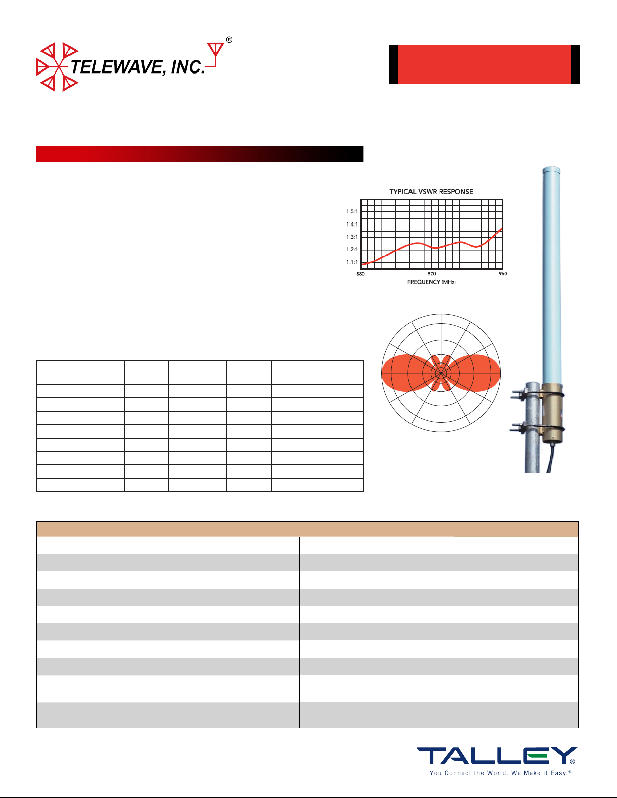
FIBERGLASS COLLINEAR ANTENNA 2.5 dBd
The Telewave Collinear line of antennas are rugged omnidirectional antennas
suited for most environments, see the exact model specifications below.
These antennas are constructed with brass and copper elements that are
soldered together; producing both a DC path to ground and preventing
internally produced intermodulation products. Telewave’s PIM-Rated
antennas are carefully built using specially treated materials and a
meticulous assembly process to achieve a -150 dBc PIM rating or better.
The “Cool Blue” fiberglass radome provides maximum protection from
corrosive gases, ultraviolet radiation, icing, acid rain, and wind-blown abrasives.
Intrusion and water protection is equivalent to an IP24 rating.
When ordering, specify all TX and RX frequencies that will be used on the
antenna. Telewave’s support can assist with any special mounting needs.
Part Number Connector Jumper Clamp Kit
(Included)
ANT900F2 N-F 24” RG213 M-M ANTC485 Clamps Bottom (Normal)
ANT900F2-I N-F 24” RG213 M-M ANTC485 Clamps Top (Inverted)
ANT900F2-DIN DIN-F None ANTC485 Clamps Bottom (Normal)
ANT900F2-IDIN DIN-F None ANTC485 Clamps Top (Inverted)
ANT900F2-PIM DIN-F None ANTC485 Clamps Bottom (Normal)
ANT900F2-IPIM DIN-F None ANTC485 Clamps Top (Inverted)
ANT900F2-PIM-PIP DIN-F None ANTC485 Clamps Bottom (Normal)
ANT900F2-IPIM-PIP DIN-F None ANTC485 Clamps Top (Inverted)
Mounting
880 - 960 MHz
PIM/PIP Models Available
Part:ANT900F2-PIM, PIM - Only
Part:ANT900F2-PIM-PIP, PIM + PIP
60
30
0
-30
-60
90
-3
-10
-20
-90
Vertical Plane
Gain = 2.5 dBd
Antenna Patttern available on website
60
30
0
-30
-60
(Mast not included)
SPECIFICATIONS
Frequency (continuous) 880 - 960 MHz Passive intermodulation rating* -150 dBc or better
Gain 2.5 dBd PIP rating** 25 KW
Power rating (Type.) 500 watts Tower weight (antenna + clamps) 8 lbs.
Impedance 50 ohms Wind rating / with 0.5” ice 225 / 175 MPH
Input VSWR 1.5:1 or less Maximum exposed area 0.9 ft.²
Pattern Omnidirectional Lateral thrust at 100 MPH 35 lbs.
Vertical beamwidth
Coastal / Salt Air Suitable No
Temperature range
* Specifications applicable only to PIM-Rated
Models
Questions? Visit www.Talleycom.com or contact Talley at 800.949.7079 or Sales@Talleycom.com today.
38°
-58 to +140 °F
-50 to +60 °C
** Specifications applicable only to PIPRated Models
Shipping weight
Full antenna dimensions (L x D) in (cm) 38 x 2.75 (96.52 x 7)
Base pipe dimensions (L x D) in (cm)
Radome dimensions (L x D) in (cm)
Shipping dimensions (L X W X H) in (cm)
10 lbs.
11.5 x 2.75 (29.21 x 7)
26.5 x 2.5 (67.31 x 6.35)
44 x 7 x 5
(111.76 x 17.78 x 12.7)
INSTALLATION GUIDE
FOR COLLINEAR ANTENNAS MODELS: F2
WARNING:
For your safety, do not install any antenna near power lines and
carefully follow all installation instructions. Always use safety devices for
tower climbing. Ensure that the tower structure is well grounded for
lightning protection.
If the antenna falls toward or contacts any overhead wires, IMMEDIATELY
LET GO and stay away. Contact the utility company for assistance.
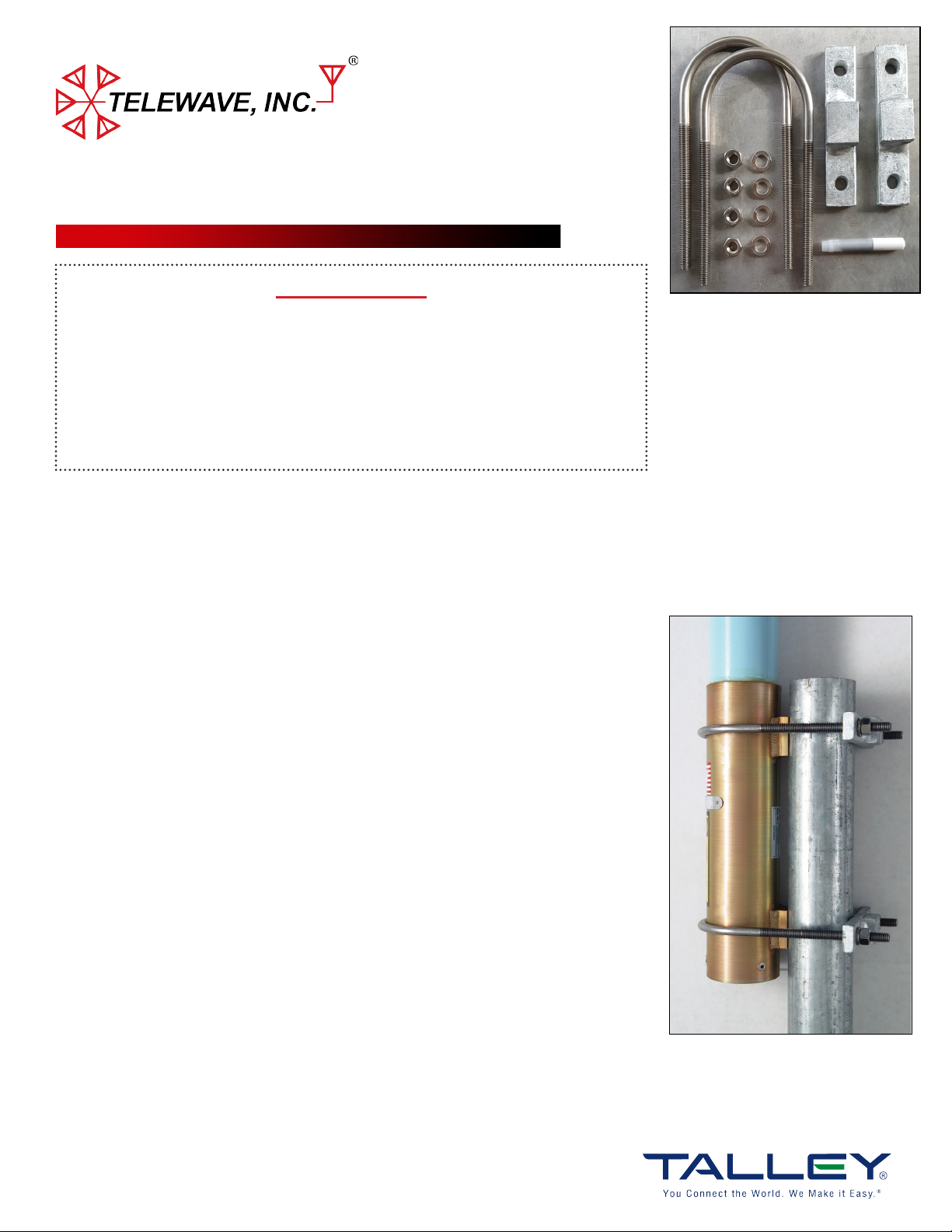
Figure 1: ANTC485 Clamp Kit
Clamp Kit Contents (Figure 1):
(2) Clamp Plates
(2) 3/8”-16 Stainless U-Bolts
(4) Hex Nuts
(4) Lock Washers
(1) Tube of Anti-Seize Compound
IMPORTANT - BEFORE ASSEMBLING AND MOUNTING
Both clamps must be properly installed and spaced to prevent antenna rotation from
wind load. Make sure you have all parts ready prior to installation, see on the right.
MOUNTING INSTRUCTIONS
1. The welded mounting slots are intended to be placed against the support
structure when used with the supplied clamp set. When using any other clamp set,
the mounting slots should be turned to one side, out of contact with the
support.
2. Apply anti-seize compound to the ends of each u-bolt. Place a loosly assembled
clamp over the top of the mast. Feed the antenna base ferrule down through the
clamp until aligned with the upper attachment point. Tighten down the hex nuts
and straighten the antenna until clamped into a vertical position.
3. Attach and secure the lower antenna clamp with the supplied hex nuts and lock
washers, to provide reasonable pressure to the support structure and antenna base
ferrule.
4. Connect RF feed cable terminated with Type-N or 7-16 DIN as required to
antenna input connector. Secure all cables with UV-Resistant cable ties.
F2-SERIES DIMENSIONS
Ferrule (L x D) in (cm): 11.5 x 2.75 (29.21 x 7)
Clamp Spacing (L) in (cm): 7.5 (19)
5. Be sure to properly seal the input connector with waterproof tape or other sealing
material. Refer to Telewave TWDS-0502 for a recommended method of connector
sealing.
Questions? Visit www.Talleycom.com or contact Talley at 800.949.7079 or Sales@Talleycom.com today.
Figure 2: Typical Mounting
Configuration
 Loading...