

Page 1
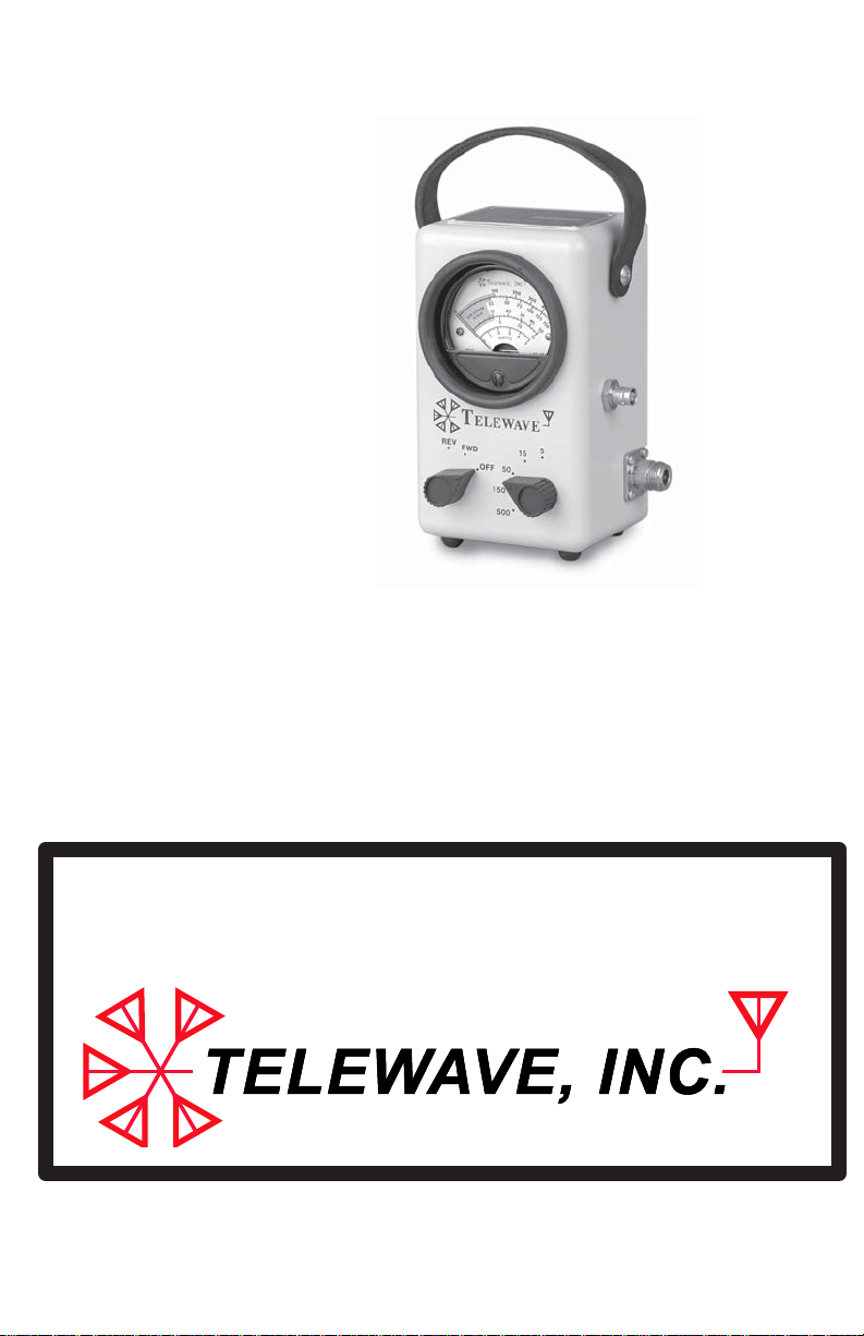
Model 44L1/L1P
BROADBAND RF
WATT METER
OPERATION MANUAL
®
Page 2

Telewave, Inc.
Model 44L1/L1P
MODEL 44L1/L1P BROADBAND RF WATTMETER
DESCRIPTION AND OPERATION
CONTENTS PAGE
1. SPECIFICATIONS 2
2. GENERAL DESCRIPTION 3
3. PHYSICAL DESCRIPTION 5
4. FUNCTIONAL DESCRIPTION
Schematic and Parts List 6
Functional Description 7
Accessory List 8
5. OPERATION
Unpacking and Connections 9
Power Measurements 10
VSWR Calculations 11
True Power at Load Calculation 11
Directivity and Insertion Error 12
6. MAINTENANCE
Warranty Service and Calibration 13
Parts Location 14
Calibration / Adjustment Procedure 15
7. REFERENCE
VSWR Nomograph 17
Jumper Cable Cutting Chart 18
Telewave, Inc. • 660 Giguere Court • San Jose, CA 95133
1-800-331-3396 • 408-929-4400 • www.telewave.com
TWDS-8011 Rev. 3/11 • All Contents © 2011 Telewave, Inc.
Page 1
Page 3

Telewave, Inc.
Model 44L1/L1P
1 SPECIFICATIONS
1.01 Table 1-1 lists specications for the Telewave Model 44L1/L1P
Broadband RF Wattmeter. These are provided to assist the user in
formulating acceptance criteria, determining applications, and for
periodic recalibration of the instrument. Minor deviations from
these specications which do not affect performance of the Model
44L1/L1P Wattmeter should not be considered a warranty issue.
Table 1-1: Model 44L1/L1P RF Wattmeter Specications
Parameter Characteristics
Frequency Range
Accuracy
2 to 200 MHz
± 7 percent of full scale
(Specied with N connectors only)
Power Ranges 5, 15, 50, 150 and 500 Watts
Primary Line Impedance
VSWR
Insertion Loss
50 Ohms nominal
1.1 maximum
0.1 dB maximum
RF Sample Port (44L1P) -40 dB +/- 2 dB
RF Connectors
Standard
Optional
QC - “Quick-Change” type
N-Female
UHF, BNC, TNC, 7-16 DIN M/F
Dimensions
Height
Width
Depth
Weight
6.625 in. (16.83 cm)
4 in. (10.16 cm)
3.25 in. (8.26 cm)
3 lb. (1.36 kg)
Page 2
Page 4

Telewave, Inc.
Model 44L1/L1P
2 GENERAL DESCRIPTION
2.01 This manual provides the physical and functional description and
operating theory necessary for effective use of the Telewave Model
44L1/L1P Broadband Radio Frequency (RF) Wattmeter. Its features
include:
• Displays ve power ranges
• Measures 1 to 500 watts
• Does not require inserts
• Does not require band switching
• Fully operable in freezing conditions
• Provides 5 watts full scale range
• Interchangeable connectors (QC)
• Lightweight, rugged and easy to carry
• -40 dB RF sampling port (Model 44L1P)
2.02 The instrument integrates two broadband directional couplers for
measuring incident and reected power, ranging, calibration and
display. The wide coverage and dynamic range of this instrument
eliminates any inserts or band switching. A 20 uA taut band me-
ter movement is used to display the measured power, providing the
measurement accuracy necessary to tune low power portable trans-
mitters.
2.03 A convenient, easy to read, voltage standing wave ratio (VSWR)
chart is provided on the rear of the instrument for determining
VSWR from the measured incident and reected power levels. The
instrument is designed for rugged eld use and is housed in a diecast
metal case with a leather carrying strap. The measurement circuits
in the wattmeter are driven directly by the current developed in the
coupler, making it unnecessary to supply AC power or batteries. A
carrying case (Model TC44) is available as an option. The Model
44L1/L1P is ideally suited for mobile, marine, and aircraft applica-
tions as well as base stations.
Page 3
Page 5
Telewave, Inc.
Model 44L1/L1P
1
2
3
4
5
7
6
8
9
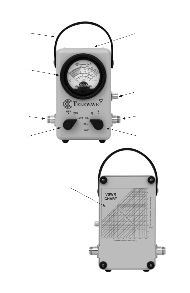
Figure 2-1: Model 44L1/L1P
Broadband RF Wattmeter
Controls and Indicators
Page 4
Page 6

Telewave, Inc.
Model 44L1/L1P
3 PHYSICAL DESCRIPTION
3.01 The controls and indicators of the Model 44L1/L1P Broadband RF
Wattmeter are illustrated in Figure 2-1, and the functions of these
elements are described in Table 3-1.
Table 3-1 : Model 44L1/L1P Description
Key Item Description
1 Carry Strap For carrying or hanging the instrument.
2 Identication Label
Contains model and serial number of the
instrument.
3 Meter Displays measured power.
4 Sample Port
Connection point for external measure-
ment or signal injection (Model 44L1P).
Connection point for the RF source, such
5 Input Connector
as an RF power amplier or transmitter.
Mates with Type N or UHF connector
(typical).
Connection for the RF load, such as an an-
6 Output Connector
tenna or dummy load. Mates with Type N
or UHF connector (typ.)
(1) OFF – Transit. Provides protection
for meter during instrument
7 Mode Switch
(2) FWD – Displays forward or incident
movement.
power.
(3) REV – Displays the reected power.
8 Power Range Switch Selects one of 5 full scale power ranges.
9 VSWR Chart
Provides a method to calculate VSWR
from the measured forward and reected
power.
Page 5
Page 7
Telewave, Inc.
Model 44L1/L1P
RF
SOURCE
R19
R15
R11
R1
R3
R7
5
15
R4
50
R8
150
R12
500
R16
-
+
M1
REVFWD
5
S2
15
50
150
500
A1
Dual Directional Coupler
OFF
S1
R13
R17
R2
R5
R6
R9
R10
R14
R18
R20
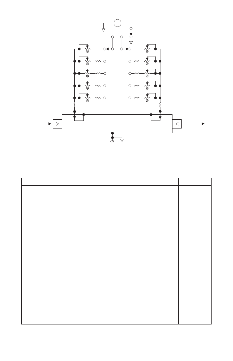
Figure 3-1: Model 44L1/L1P RF Wattmeter Schematic
Table 3-2 : Model 44L1/L1P Parts List
REF DESCRIPTION MFG MFG P/N
M1
MP1
MP2
MP6
MP8
MP9
QC
QC
QC
QC
QC
R1
R2
R3
R4
R5
R6
R7
R8
R9
R10
R11
R12
R13
R14
R15
R16
R17
R18
R19
R20
S1, 2
METER: 20 UA
KNOB
SCREW: BUMPER 6-32
STRAP: LEATHER
SCREW: TRUSS HEAD 10-52
SHOCK RING: EDM
N FEMALE CONNECTOR
UHF FEMALE CONNECTOR
BNC FEMALE CONNECTOR
TNC FEMALE CONNECTOR
7-16 DIN FEMALE CONNECTOR
RESISTOR: VAR CC 0.25W 10% 50K OHM
RESISTOR: VAR CC 0.25W 10% 50K O H M
RESISTOR: VAR CC 0.25W 10% 50K OHM
RESISTOR: FXD CC 0 . 5 0 W 5% 7.5K OHM
RESISTOR: FXD CC 0 . 5 0 W 5% 7.5K OHM
RESISTOR: VAR CC 0.25W 10% 50K OHM
RESISTOR: VAR CC 0.25W 10% 50K OHM
RESISTOR: FXD CC 0 . 5 0 W 5% 62K OHM
RESISTOR: FXD CC 0 . 5 0 W 5% 62K OHM
RESISTOR: VAR CC 0.25W 10% 50K OHM
RESISTOR: VAR CC 0.25W 10% 100K OHM
RESISTOR: FXD CC 0 . 5 0 W 5% 130K OHM
RESISTOR: FXD CC 0 . 5 0 W 5% 130K OHM
RESISTOR: VAR CC 0.25W 10% 100K OHM
RESISTOR: VAR CC 0.25W 10% 100K OHM
RESISTOR: FXD CC 0 . 5 0 W 5% 300K OHM
RESISTOR: FXD CC 0 . 5 0 W 5% 300K OHM
RESISTOR: VAR CC 0.25W 10% 100K OHM
RESISTOR: FXD CC 0 .25W 5% 51 OHM
RESISTOR: FXD CC 0 .25W 5% 51 OHM
SWITCH: ROTARY 2 POLE 5 POS
TRIPLETT
RAYTHEON
TELEWAVE
TELEWAVE
ICO-RALLY
TELEWAVE
TELEWAVE
TELEWAVE
TELEWAVE
TELEWAVE
TELEWAVE
ELECTROSWITCH
RF
LOAD
7034
MS-91528-1P2B
TB44
HH44
SCR-813
7099
QC44N
QC44S
QC44B
QC44T
QC44D
D3G0205N-4096
Page 6
Page 8

Telewave, Inc.
Model 44L1/L1P
4 FUNCTIONAL DESCRIPTION
4.01 The Model 44L1/L1P Wattmeter is made up of two major sections.
Refer to the schematic diagram in Figure 3-1 for this description.
(a) A Dual RF Directional Coupler with directivity of greater than
25 dB.
(b) A voltmeter circuit. Five ranges are provided.
4.02 The 50 ohm Dual Directional Coupler A1 samples a small amount
of the incident or forward RF power delivered to the load. The cou-
pler incorporates two RF detectors which produce a DC voltage
proportional to the sampled RF power. A small amount of power
reected from the load is also sampled.
4.03 Mode Switch S1 determines which of these voltages is displayed on
the meter, M1. The RF Power Range Switch S2, selects the appro-
priate range and calibration resistors for the power to be measured.
Each range is provided with an adjustable internal potentiometer for
range calibration.
4.04 Meter M1 displays ve scales which correspond to the RF Power
Range Switch positions. The lower third of the meter scale is shaded
red, alerting the user to switch to a lower power range for improved
accuracy. An OFF position is provided on Mode Switch S1, which
shunts out the meter movement. This provides protection for the
sensitive meter when the instrument is being transported.
4.05 Model 44L1P provides an RF sampling port with an output of -40
dB (+/- 2 dB) below the transitional line level to use for measurement of frequency, spectrum analysis, to inject a signal for measure-
ment of receiver sensitivity, or other applications. The port coupling
is not directional; in a high VSWR system, the sampling port output
will be -40 dB below the total power passing through the instru-
ment.
Page 7
Page 9
Telewave, Inc.
Model 44L1/L1P
Optional Accessories
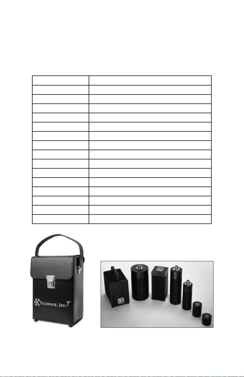
4.06 The table below lists the most common accessories for the Model
44L1/L1P Wattmeter. Consult the current price list or our website
for current pricing.
Part Number Description
TC44 Leather carry case with accessory pouch
TWL-35 Coaxial Dry Load - 35 watts
TWL-50 Coaxial Dry Load - 50 watts
TWL-60 Coaxial Dry Load - 60 watts
TWL-75 Coaxial Dry Load - 75 watts
TWL-100 Coaxial Dry Load - 100 watts
TWL-150 Coaxial Dry Bench Load - 150 watts
TWL-300 Coaxial Dry Bench Load - 300 watts
QC44B Quick Change BNC-female connector
QC44D Quick Change 7-16 DIN-female connector
QC44N Quick Change N-female connector
QC44S Quick Change UHF-female connector
QC44T Quick Change TNC-female connector
ANTA-02-5 Jumper - RG-213/U, 5 ft., N-Male
ANTD-03-5 Jumper - RG-142B/U, 5 ft., N-Male
Page 8
Figure 4-1: Optional TC44 Carrying Case and RF Loads
Page 10

Telewave, Inc.
Model 44L1/L1P
5 OPERATION
Unpacking
5.01 After the Model 44L1/L1P Wattmeter arrives, examine the ship-
ping container for visible loss or damage. Carefully unpack the
wattmeter and examine the exterior for damage.
IMPORTANT
The Model 44L1/L1P Wattmeter is carefully tested, inspected,
and packed before leaving the Telewave factory. Claims for loss
or damage sustained in transit should be made upon the carrier,
NOT TO Telewave, Inc., as follows:
(1) Visible Loss or Damage - Any evidence must be noted on
the freight bill or express delivery sheet. The form required
to le such a claim will be supplied by the carrier.
(2) Concealed Loss or Damage - This damage does not be-
come evident until after the wattmeter is unpacked. When
the damage is discovered, make a written request for in-
spection by the carrier’s agent within fteen (15) days of
the delivery date. File a claim with the carrier.
RF Connections
5.02 The following procedure will assist the user in preparation for
making an RF power measurement. Refer to Figure 2-1.
Step Procedure
1 Remove the RF power from the transmission line.
Page 9
Page 11

Telewave, Inc.
Model 44L1/L1P
Step Procedure
2 Set the RF Range Switch to the 500 Watt position.
3 Connect the RF Source to the Model 44L1/L1P FWD input
connector, located on the left side of the instrument nearest the
mode switch.
4 Connect the RF Load to the Model 44L1/L1P FWD output
connector, located on the right side of the instrument nearest the
range switch.
Forward Power Measurement
5.03 The following procedure will assist the user in making an incident
or forward power measurement. Refer to Figure 2-1.
Step Procedure
1 Set the Mode Switch to the FWD position.
2 Apply RF power to the transmission line.
3 Move the RF Range Switch to a lower range if necessary to
obtain a reading in the upper third of the scale.
4 Note the meter reading.
Reected Power Measurement
5.04 The following procedure will assist the user in making a reected
or reverse power measurement.
Step Procedure
1 Set the Mode Switch to the REV position.
2 Repeat Step 2 of 5.03.
3 Repeat Step 3 of 5.03.
Page 10
Page 12
Telewave, Inc.
Model 44L1/L1P
VSWR Calculation
5.05 The following procedure will assist the user in determining the
Voltage Standing Wave Ratio.
Step Procedure
1 Perform the procedures outlined in 5.03 and 5.04. Record the
true incident and reected power.
2. Refer to the VSWR Chart on the rear of the instrument or Figure
7-1. Apply the readings from Step 1 to the chart.
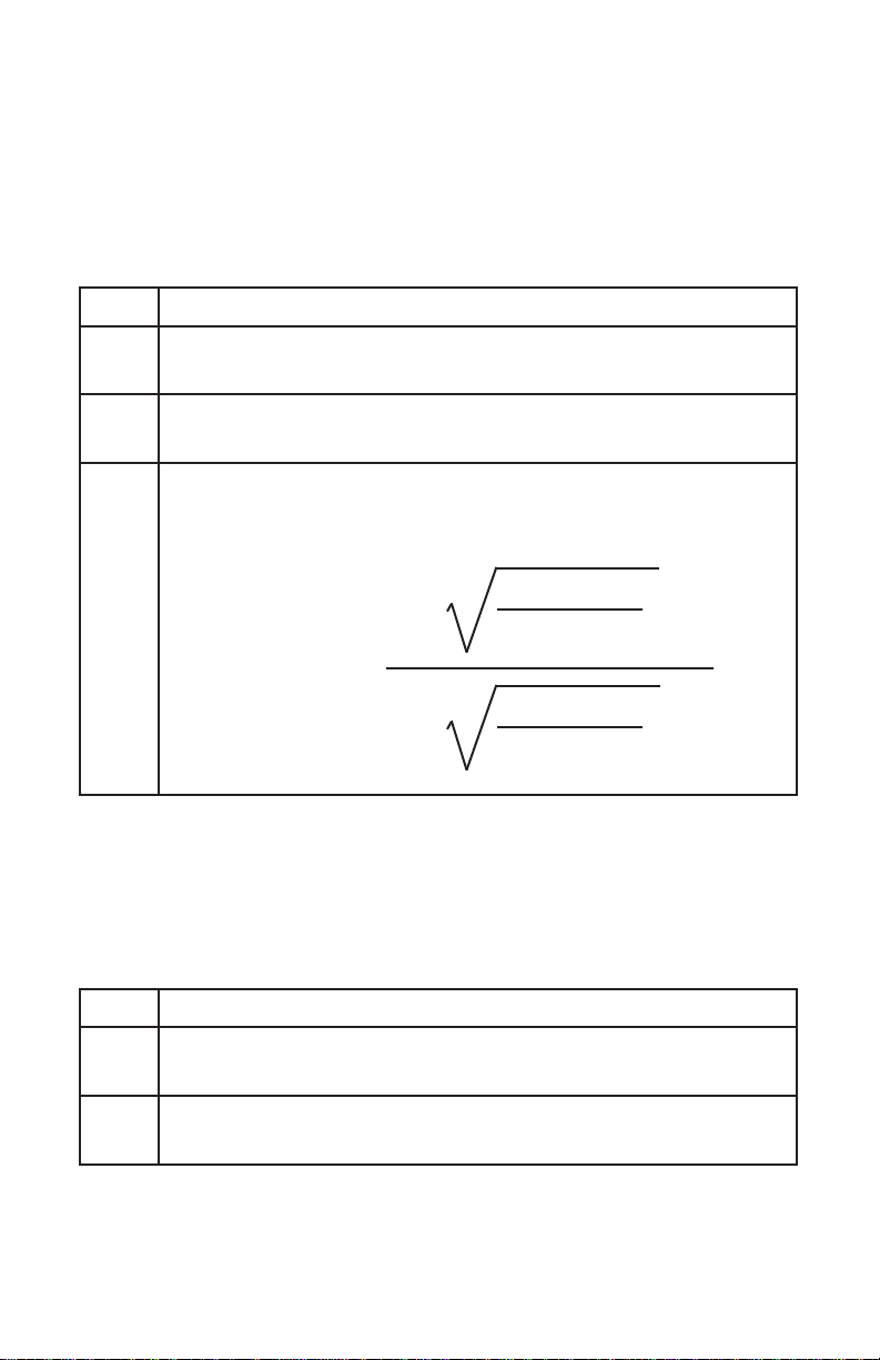
3. The VSWR is read from the nearest sloping line. For higher
accuracy, calculate the VSWR by the formula:
P
(Watts)
1 +
P
REV
FWD
(Watts)
VSWR =
P
(Watts)
1 -
P
REV
FWD
(Watts)
True Power at Load Calculations
5.06 The following procedure will assist the user in determining the
actual power delivered to the load.
Step Procedure
1 Perform the procedures outlined in 5.03 and 5.04. Record the
true incident and reected power.
2 Subtract the reected power from the incident power.
This difference is the true power at the load.
Page 11
Page 13

Telewave, Inc.
Model 44L1/L1P
Directivity Error
5.07 Directivity error results from the effect of imperfect directivity in the
Dual Directional Coupler. Directivity is the ability of the coupler to
sense power owing in one direction and be insensitive to any power
which may be owing in the reverse direction. The directivity error
is included within the specied instrument accuracy.
Insertion Error
5.08 When the RF load and RF source are well matched, any error con-
tributed by inserting the Model 44L1/L1P Wattmeter alone is negli-
gible. However, the use of a jumper cable to connect the wattmeter
in the system will change the characteristic impedance of the line,
especially in a system with high VSWR. Since the impedance on
either side of 1/2 wavelength is identical, the jumper cable added to
the input or output of the Model 44L1/L1P should be of an appro-
priate length to equal 1/2 wavelength at the frequency of operation,
thus eliminating any error due to the additional length.
5.09 The chart shown in Figure 7-2 shows the required length (including
connectors) of RG-213/U cable to act as a 1/2 wave line section at
frequencies from 25-200 MHz.
Page 12
Page 14

Telewave, Inc.
Model 44L1/L1P
6 MAINTENANCE
6.01 The Model 44L1/L1P Wattmeter is designed with high reliability
components and operates on low DC power levels. It can be expected to operate at peak performance for long intervals. Periodic cali-
bration by Telewave or an RF standard laboratory is recommended
to maintain peak instrument performance.
Warranty Service
6.02 The Model 44L1/L1P Wattmeter is covered under Telewave’s stan-
dard 1 year warranty. See the inside back cover for exact terms.
Faulty units should be returned to:
Telewave, Inc.
ATTN: Repairs
660 Giguere Court
San Jose, CA 95133
1-800-331-3396 / +1 408-929-4400
6.03 A Return Material Authorization (RMA) is required when prod-
ucts are returned to Telewave. The following information will be
requested in order to assign an RMA:
• The Model 44L1/L1P serial number. The ID plate is located
on the top of the instrument. Include the date of purchase and
Purchase Order number if known.
• A brief statement of the problem.
• Contact name, telephone number, and return shipping address.
Calibration
6.04 Adjustments to the instrument should be performed by Telewave,
or other RF calibration laboratory. Calibration or adjustment should
be made at a frequency of 100 MHz when possible. The adjustment
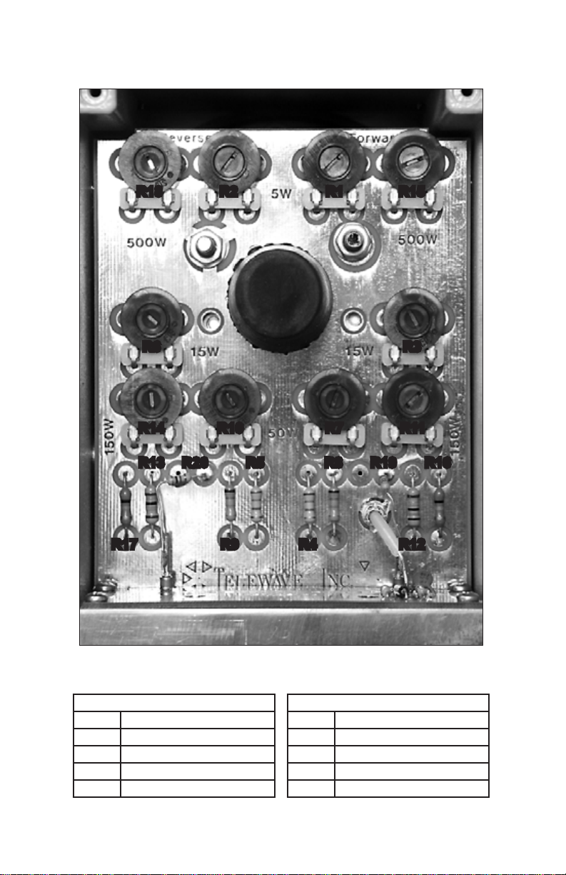
potentiometers are located on the main PC board inside the instru-
ment. Refer to Figure 3-1 and 6-1.
Page 13
Page 15
Telewave, Inc.
Model 44L1/L1P
R18 R2 R1 R15
R6 R3
R14 R11R10 R7
R20 R19R13
R17
R9
R5
R8
R4 R12
Figure 6-1: Adjustment Potentiometers and Parts Location
REVERSE RANGES
R2 5 watt range
R6 15 watt range
R10 50 watt range
R14 150 watt range
R18 500 watt range
Page 14
FORWARD RANGES
R1 5 watt range
R3 15 watt range
R7 50 watt range
R11 150 watt range
R15 500 watt range
R16
Page 16

Telewave, Inc.
Model 44L1/L1P
Variable
RF Power
Source
Low
Pass
► ► ►►
Filter
Model 44L1
Under
Calibration
In-Line
Calibrated
Attenuator
Figure 6-2: Calibration / Adjustment Equipment Setup
6.05 Calibration / Adjustment Requirements and Equipment
a) The ambient temperature during calibration must be 72.4
degrees.
b) The Telewave meter must be calibrated in the intended operating
position, either vertical or horizontal. Meters are calibrated by
Telewave in the vertical position
.
c) The Telewave wattmeter and any interconnections must use only
Type N connectors.
d) An RF power source capable of producing at least 325 watts
continuous power at 100 Mhz.
e) A low pass lter capable of handling at least the maximum
continuous power used during calibration must be installed
between the RF source and the Telewave meter.
Power
Sensor
f) A calibrated digital power meter and remote sensor, with
accuracy of +/- 0.5% or better, traceable to NIST. Insertion loss
of all test equipment must be characterized.
g) A 50 ohm inline attenuator capable of handling the maximum
continuous power that will be used during calibration.
Caution: Do not drive the meter beyond full scale, and do not apply
more than 500 watts input power at any time.
Page 15
Page 17

Telewave, Inc.
Model 44L1/L1P
6.06
Remove the four bumper screws from the rear panel. Remove
the rear panel. Figure 6-1 illustrates the adjustment locations.
Refer to Figure 6-2, Equipment Setup. Perform the calibration /
adjustment for Forward and Reverse direction as follows:
6.07 Forward Mode Adjustment
Step Procedure
1a Set the RF source to 100 MHz.
1b Set the wattmeter Mode Switch to FWD position.
1c Set the wattmeter RF Range Switch to the 5 watt range.
1d Set the RF source to 4 watts output.
1e Adjust R1 until the Telewave wattmeter reads 4 watts.
2a Set the wattmeter RF Range Switch to the 15 watt scale.
2b Set the RF source to produce 11 watts output.
2c Adjust R3 until the Telewave wattmeter reads 11 watts.
3a Set the wattmeter RF Range Switch to the 50 watt scale.
3b Set the RF source to produce 35 watts output.
3c Adjust R7 until the Telewave wattmeter reads 35 watts.
4a Set the wattmeter RF Range Switch to the 150 watt scale.
4b Set the RF source to produce 105 watts output.
4c Adjust R11 until the Telewave wattmeter reads 105 watts.
5a Set the wattmeter RF Range Switch to the 500 watt scale.
5b Set the RF source to produce 325 watts output.
5c Adjust R15 until the Telewave wattmeter reads 325 watts.
Reverse Mode Adjustment
6.08
6a Disable the RF source output
6b Set the wattmeter Mode Switch to REV position.
6c Reverse the wattmeter RF connections in the RF line.
6d Repeat Steps 1c through 5c for the 5, 15, 50, 150 and 500 watt
ranges, using adjustment points R2, R6, R10, R14, and R18.
6e Reinstall the rear panel and bumper screws.
Page 16
Page 18

Telewave, Inc.
Model 44L1/L1P
7 REFERENCE
7.01 Part 7 contains additional data for the Model 44L1/L1P RF Watt-
meter which is helpful in making low frequency and VSWR mea-
surements.
7.02 Figure 7-1 (below) shows a nomograph for estimating VSWR
from the measured incident and reected power. See 5.05 for cal-
culation procedures.
100
50
R
20
10
5
2
1
0.5
0.2
E
F
L
E
C
T
E
D
P
O
W
E
R
W
A
T
T
S
)
(P
REV
VSWR
CHART
8
10.00
5.00
4.00
3.00
2.50
2.00
1.75
1.60
1.50
1.40
1.30
1.25
1.20
1.15
1.12
1.10
FORWARD POWER - WATTS (P
FWD
Figure 7-1: VSWR Chart
0.1
500200100502010521
)
Page 17
Page 19

Telewave, Inc.
Model 44L1/L1P
7.03 Figure 7-2 shows a chart for a jumper cable to be used inline with
the Model 44L1/L1P Wattmeter to minimize potential measure-
ment errors in systems with high VSWR. The chart shows lengths
for a 50-ohm, RG-213 jumper cable, including N connectors,
using a velocity factor of 0.66 for the cable and connectors. The
jumper cable and wattmeter together should equal as close to 1/2
wavelength equivalent as possible, at the test frequency.
MHZ INCHES
25 = 153.23
30 = 127.25
35 = 108.69
40 = 94.78
45 = 83.95
50 = 75.29
55 = 68.21
60 = 62.30
65 = 57.31
70 = 53.03
75 = 49.32
80 = 46.07
85 = 43.20
90 = 40.66
95 = 38.38
100 = 36.33
105 = 34.47
110 = 32.78
MHZ INCHES
115 = 31.24
120 = 29.83
125 = 28.53
130 = 27.33
135 = 26.22
140 = 25.19
145 = 24.23
150 = 23.34
155 = 22.50
160 = 21.71
165 = 20.98
170 = 20.28
175 = 19.63
180 = 19.01
185 = 18.42
190 = 17.87
195 = 17.34
200 = 16.84
Figure 7-2: RG-213 Jumper Cable with N-Male Connectors
Page 18
Page 20

PRODUCT WARRANTY
Products sold by Telewave, Inc. and covered by this Warranty are warranted to be
free from defects in material and work man ship at the time of and for a period of
one (1) year after delivery to the Buyer. Seller’s entire warranty obligation is limited
to making adjustments by repair, replacement, or refunding the purchase price of
any product which is returned to the Seller as provided below within one (1) year
from the date of shipment by the Seller. In no event shall Seller be liable for direct,
special, or consequential damages for breach of warranty.
Adjustment will not be allowed for products which have been damaged by lightning,
subjected to abuse, im prop er application or installation, alteration or accident, or
negligence in use, storage, trans por ta tion or han dling. Alteration or removal of
the serial number or identifi cation markings voids the Warranty. Seller shall have
the right of fi nal determination as to the existence and cause of a defect, whether
adjustment will be allowed, and if allowed, whether adjustment will be by repair,
replacement, or refund. Where adjustment is not allowed, a charge of 5% of the
original purchase price will be made to the Buyer to cover the Seller’s cost of inspection and handling.
Shipping and packaging instructions must be obtained from the Seller before products are returned for ad just ment. The Buyer will pay for packing, transportation,
and transit insurance costs for returned products. The Seller reserves the right to
dis con tin ue models at any time or change spec i fi ca tions, design, or price without
notice and without incurring any obligation. Products will be returned to the Buyer
with trans por ta tion cost collect.
Subject to the provisions of its “Patent Indemnity” clause, the Seller also warrants
that it has the right to sell its products, that the Buyer shall have and enjoy quite
possession thereof as against any lawful claims existing at the time of the sale by
the Seller, and that said products are free from any charge of encumbrance in favor
of third persons existing at the time of sale by the Seller.
The foregoing constitutes the Seller’s entire warranty, express, implied or statutory
with respect to its products and states the full extent of its liability for breach of Warranty and for damages, whether direct, special or consequential resulting form any
such breach. No change what so ev er thereto shall be binding upon the seller unless
made in writing and signed by a duly authorized representative of the Seller.
TELEWAVE, INC.
660 Giguere Court
San Jose, CA 95133 USA
1-800-331-3396
+1 408-929-4400
 Loading...