

Page 1
TELE-POD/SKY TOUR INSTRUCTIONS
Parts Check List
•Tele-Pod Mount (head with attached encoders and tripod) •Mount Handle
•Eyepiece Caddy Set [with (4) ¼"-20 button head screws & (4) Thumb Knobs
attached and (2) 2"-1¼" Caddy Inserts installed]
•Sky Tour Caddy Plate •Sky Tour Computer
•Sky Tour Operating Guide & Sky Tour Database
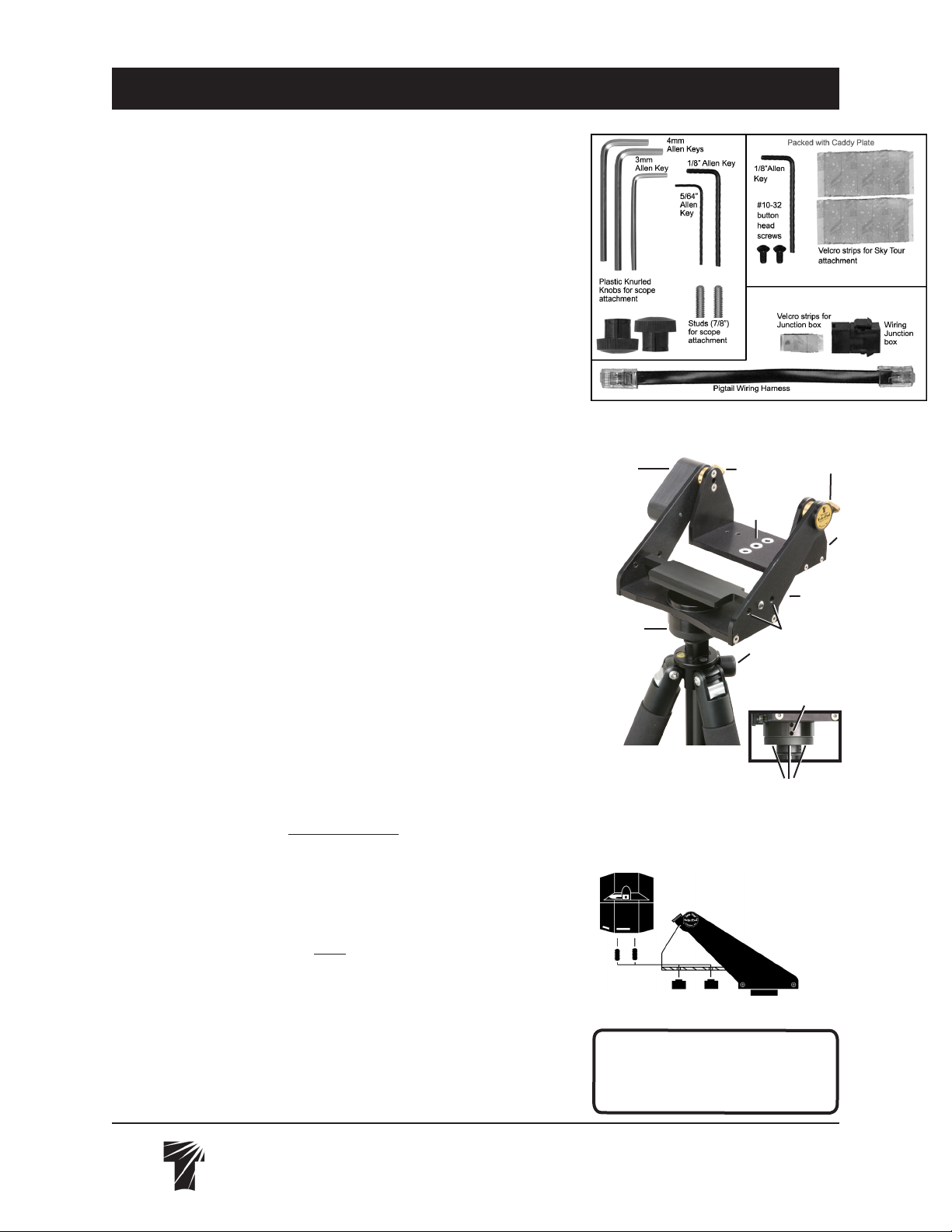
•Small-Parts Bags include: (1) Pigtail Wiring Harness, (1) Wiring Harness Junction
box, (1) Velcro strip for Junction box, (2) Studs for scope attachment, Allen Keys:
[(1) 1/8" , (1) 5/64" Allen Key, (1) 3mm, (2) 4mm], (2) Plastic Knurled Knobs
for scope attachments, (2) #10-32 button head screws for Sky Tour Caddy Plate
attachment, (1) 1/8" Allen for Caddy Plate attachment, (2) Velcro strips for Sky
Tour attachment
INTRODUCTION
Thank you for purchasing the Sky Tour equipped, Tele-Pod Mount. The lightest, simplest travel mount with digital setting circles you can nd. The Tele-Pod combines
the size, weight and exibility of a photo-tripod with the smooth, balanced altitude/
azimuth motions of our yoke and cradle mount head. The addition of the Sky Tour
computer greatly enhances your fun and capability. This instruction sheet covers
the basic set-up and operation of the mount. Please refer to the Sky Tour Operating
Guide for specic instructions on use of the computer.
COMPONENTS
The Tele-Pod consists of the mount head with attached encoders and main wiring
harness, and tripod. The head supports the scope and provides both vertical and
horizontal motions. It features smooth operating altitude and azimuth bearings, and
a Delrin scope stop in case the objective end accidentally “nose-dives.”
The tripod supports the head and allows height adjustment of the scope. The tripod
legs have rubber feet. See separate instruction sheet for more features of the tripod.
The Eyepiece Caddy Set mounts to the Yoke arms of the Tele-Pod head and
provides a place to put 5 eyepieces. The Sky Tour Caddy Plate attaches to either
the left or right Caddy bracket, which places the computer at your ngertips.
Familiarize yourself with the parts on the assembly photos for easy reference
and you will quickly learn how to put your Tele-Pod to best use.
TRIPOD SET-UP
WARNING: If setting up on a slope, ensure that the tripod legs are extended so
that the head is approximately level with the horizon. Failure to do so could cause
the telescope to tip over! This risk increases when using larger, longer scopes.
1) Loosen the top leg clamps on the tripod.
2) Extend each leg so that the mount head is slightly above the desired height and
approximately level with the horizon.
3) Tighten leg clamps.
4) Spread all three tripod legs to the first click-stop and the mount head should be
at the desired height.
4a) If you need the head higher, loosen the center column’s height adjustment
lock knob and lift to the desired height. Note that the Tele-Pod’s vibration dampening
is best when the center column is not extended.
5) Follow instructions packaged with handle to attach it to the mount.
6) Note: Mount head can be moved to other Tele Vue tripods or camera tripods
by using the 5/64" Allen to loosen lower set screw on Azimuth bearing plate. Flip
over and use 3mm Allen to back off 3 small set screws on ange base. Normally
the bearing plate and ange set screws are tight to prevent unscrewing of mount
head as mount is turned in azimuth. Now unscrew the Tele Pod Head.
Loose Parts in Bags
Tele-Pod Mount as Packaged
Altitude
Encoder
Assembly
Azimuth
Bearing Plate
Altitude Tension Knobs
Stud
Clearance
Holes
Cradle
Delrin Azimuth
encoder housing/
scope stop
Yoke
Mounting Holes on
each Yoke arm for
Eyepiece Caddy Set
Height Adjustment
Lock Knob
Azimuth Bearing Plate
Lower Set Setscrew
Set Screws on
Flange Bottom
Telescope Attachment Diagram
Tele Vue
Visionary
WARNING:
Rotating the Tele-Pod
head while the azimuth tension knob
is tightened could cause the azimuth
bearing to unscrew and separate.
32 Elkay Dr., Chester, NY 10918 (845) 469-4551 www.televue.com
Page 2
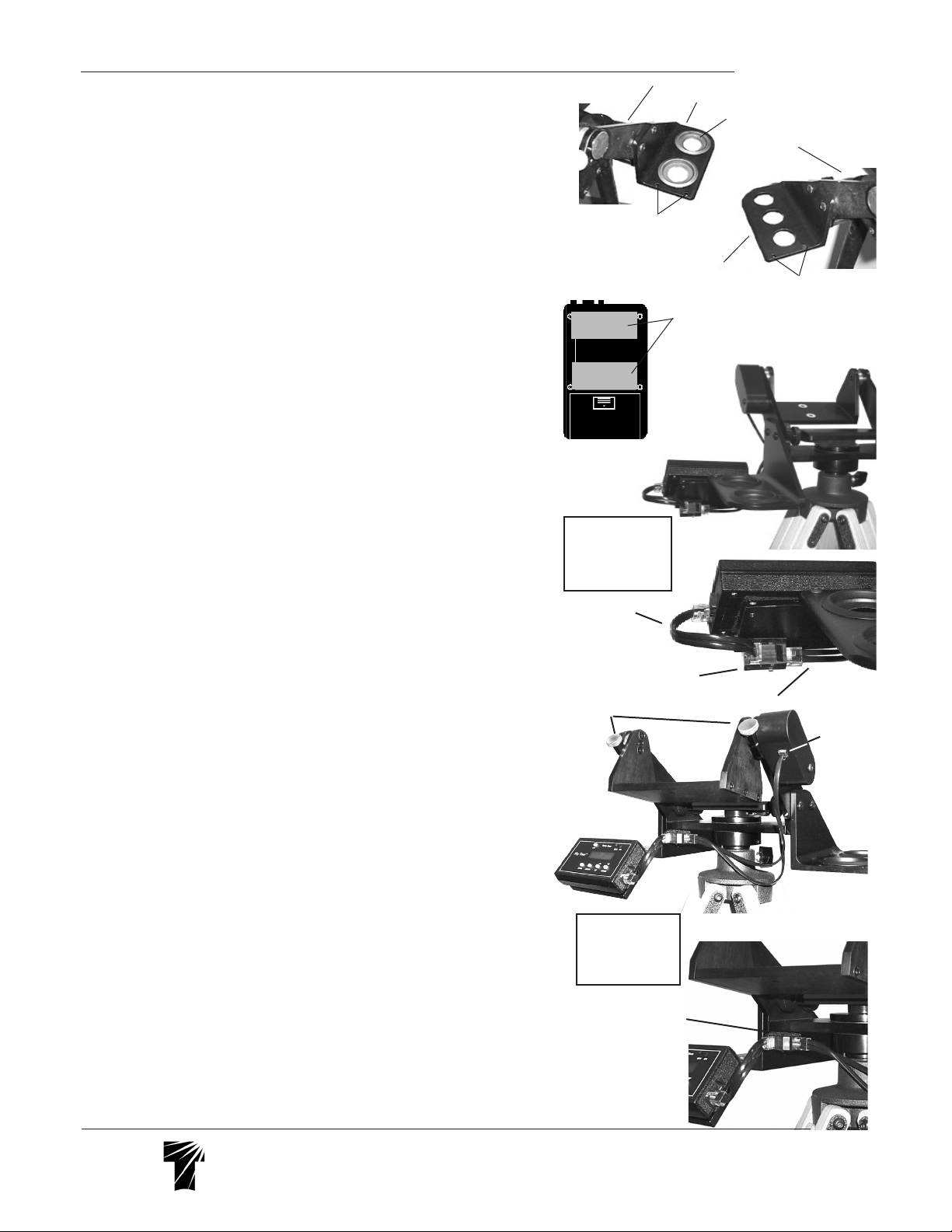
7) Sky Tour Caddy Plate Installation and Computer Attachment – The Sky Tour Caddy
Plate attaches to either the left or right eyepiece caddy using the two supplied button
head screws and Allen wrench. Keep the two halves of the Velcro strip together and
stick one side on the back of your Sky Tour computer as shown. Peel the remaining backing off of the Velcro and stick the Sky Tour computer onto the Mounting
Bracket. When using shorter scopes like our Tele Vue-76 or Tele Vue-85, make
sure you leave enough nger room between the computer and the focuser knob.
8) Sky Tour Wiring Connections
a) If the Sky Tour Caddy Plate is attached to the right Caddy, use the Velcro to stick the
Harness Junction Box to the back of the plate, in the lower right hand corner. Orient
the Box so that the Main Wiring Harness plugs straight in from the left end of the box.
The Pigtail Harness will then plug in from the front. Loop the Pigtail around and plug
it into the Sky Tour Computer.
or
b) If the Plate is attached to the left Caddy, use the Velcro to stick the Harness Junction Box to the underside of the mount head, in the left corner, against the left side
Caddy Bracket. Orient the Box so that the Main Wiring Harness plugs straight in
from the right end of the box. The Pigtail Harness will then plug into the Box directly
toward you. Plug the other end into the Sky Tour Computer.
9) Adjust the azimuth tension knob until there is a slight amount of tension. Place
the cradle in approximately level position as indicated by the altitude alignment
marks (drilled hole on one of the side altitude bearings, forming two semi-circles).
Tighten the vertical tension knobs.
Telescope Attachment
1) Thread the two studs into the two end holes on the bottom of your telescope
mount ring. Snug tight using the supplied Allen key.
2) With the cradle approximately level, set the scope down within it so that the
studs pass through the clearance holes and the telescope's eyepiece end is closer
to the Altitude Tension Knobs.
3) Lock the scope down with the supplied wing nuts.
Telescope Use
1) Place eyepiece in scope.
2) Apply slight and equal tension to altitude bearings using the altitude bearing
tension knobs.
3) Swing the scope up approximately 45° and check balance. If the scope wants to
swing back down, slide the scope back in the mount ring until balance is achieved.
If the scope wants to swing up, push it forward until balance is achieved.
4) Apply more tension to achieve the desired feel. Extra tension can be used to
overcome a minor out-of-balance condition. However, excessive tension will cause
the movement to be “jerky.” Severe overtightening could strip the threads in the
mount head. Azimuth tension is pre-set at the factory and should not be adjusted.
5) The basic azimuth tension is set at the factory and should not be readjusted.
Additional azimuth tension can be applied by tightening the azimuth tension screw.
6) The most stable way of slewing your scope is by grasping a xed part, (i.e.
focuser body) or mount handle. Slewing the scope by the diagonal could cause
image shift when you release.
7) When changing eyepiece, it is advisable to rst lock one of the altitude tension
screws tight before removing the eyepiece from the telescope. Once you have
changed eyepieces, loosen that altitude tension screw to resume normal movement.
Computer Alignment
Please follow the alignment instructions on page 11 in the yellow Sky Tour Operating Guide. Though the guide was originally written for the Gibraltar Mount, all
aspects of Sky Tour use apply to Tele-Pod and Panoramic mounts.
Yoke Arm
Sky Tour
Bracket Holes
1¼" Eyepiece Caddy
Right handed installation on Sky Tour
Caddy Plate as
viewed from in front
of the mount
Pigtail
Close-up of junction box
location and orientation
Altitude Tension
Knobs
Left handed
installation on Sky
Tour Caddy Plate
as viewed from
behind the mount
Close-up of junction box
location and orientation
2" Eyepiece Caddy
1¼" Removable Insert
Yoke Arm
Velcro location on
back of Sky Tour.
Main Wiring Harness
Sky Tour
Bracket Holes
Altitude
Encoder
Jack
Tele Vue
Visionary
32 Elkay Dr., Chester, NY 10918 (845) 469-4551 www.televue.com
 Loading...