

Page 1
GIBRALTAR5TM / SKY TOUR MOUNT INSTRUCTIONS
Parts Check List Parts Check List
Parts Check List
Parts Check List Parts Check List
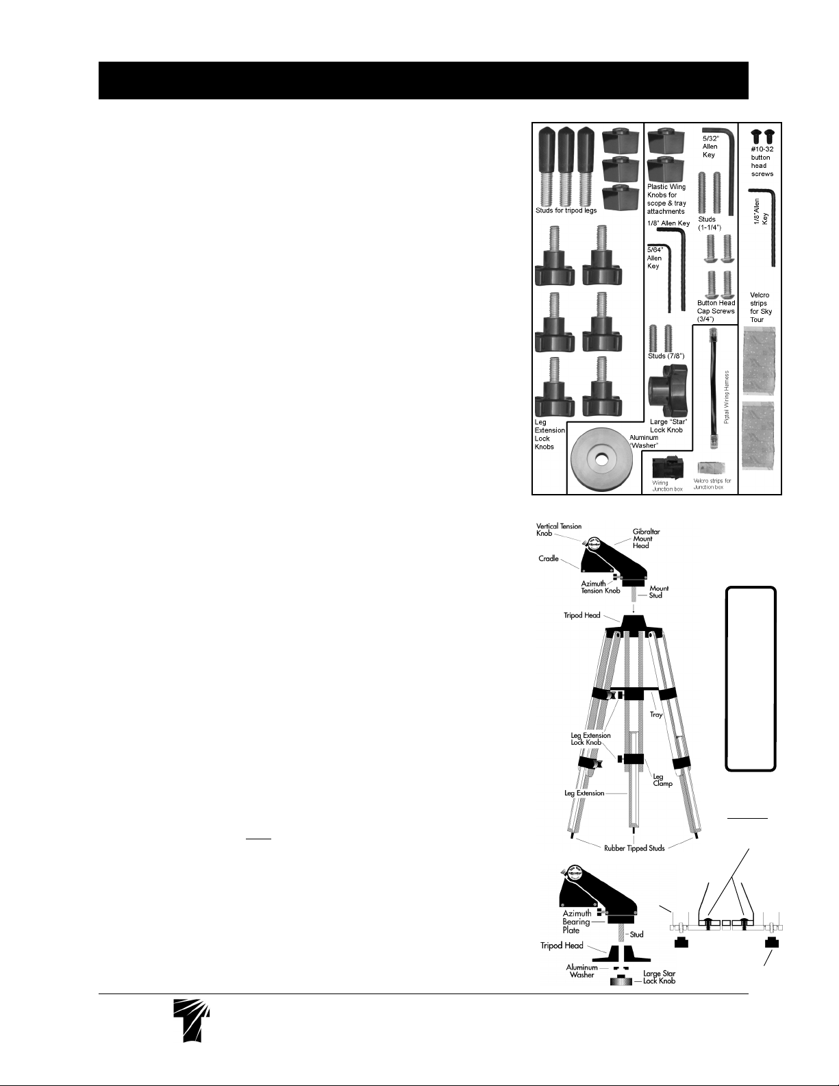
(please check various bags for small parts)
•Gibraltar5 Mount Head (with mounting stud and altitude / azimuth encoders)
•Wood Tripod •Tray
•Eyepiece Caddy Set [with (4) ¼"-20 button head screws & (4) Thumb Knobs attached and
(2) 2"-1¼" Caddy Inserts installed]
•Sky Tour Caddy Plate •Sky Tour Computer [with (1) 9V Battery]
•Sky Tour Operating Guide, Sky Tour Database, & Harrington Field Guide
•Small-Parts Bags include: (1) Pigtail Wiring Harness, (1) Wiring Harness Junction box, (1)
Velcro strip for Junction box, (3) Rubber Tipped Studs for tripod legs, (2) Studs for scope
attachment, (1) 1/8" Allen Key, (1) 5/64" Allen Key, (5) Plastic Wing Knobs for scope and
tray attachments, (6) Leg Extension Lock Knobs, (1) Large "Star" Lock Knob, (1) Aluminum
"Washer", (2) #10-32 button head screws for Sky Tour Caddy Plate attachment, (1) 1/8" Allen
for Caddy Plate attachment, (2) Velcro strips for Sky Tour attachment, (4) 3/4" button head cap
screws, (2) 1-1/4" studs, and (1) 5/32" Allen.
Introduction & Use
The alt-azimuth mount Gibraltar5TM with Eyepiece Caddy Set and Sky Tour Computer system
is designed for the 5" Tele Vue-NP127 refractor.
The Gibraltar5 Mount Head cradles the telescopes at their centers of gravity to make
operation smooth and easy. It can also accept Eyepiece Caddy Set and Sky Tour system.
To achieve smoothest operation it is important to have the telescope properly balanced in its
mount ring and the altitude and azimuth tension knobs providing minimal drag.
The tripod legs can position the cradle height from 38" to 62". The triangular accessory tray
adds extra stability to the tripod.
Gibraltar5 is the ideal travel-friendly mount for quick, convenient terrestrial and astronomical
viewing.
Tripod, Head and Sky Tour Set-up
Installing Foot Studs Installing Foot Studs
1)
Installing Foot Studs –After removing all packaging material, screw the Foot Studs into the
Installing Foot Studs Installing Foot Studs
bottom of the Leg Extensions.
Installing Leg Extension Lock KnobsInstalling Leg Extension Lock Knobs
2)
Installing Leg Extension Lock Knobs –Screw Leg Extension Lock Knobs into the metal Leg
Installing Leg Extension Lock KnobsInstalling Leg Extension Lock Knobs
Clamp bands.
Setting-up on level groundSetting-up on level ground
3a)
Setting-up on level ground –With the tripod upside down, pull the 3 Leg Extensions to the
Setting-up on level groundSetting-up on level ground
same height and lock in place with Leg Extension Lock Knobs.
Setting-up on uneven terrainSetting-up on uneven terrain
3b)
Setting-up on uneven terrain – Proceed as above, then install Tray (next step). Extend
Setting-up on uneven terrainSetting-up on uneven terrain
remaining legs until head is approximately level. Lock Leg Extension Lock Knobs. Move on to
step 5.
NOTE: The mount only needs to be sufficiently levelled so the telescope swings smoothly in any
azimuth orientation.
Installing TrayInstalling Tray
4)
Installing Tray – With tripod right side up, spread apart tripod legs. Install Tray with edge
Installing TrayInstalling Tray
lip up. Insert the stud from one of the hinged Tray Supports through the hole in one corner of the
Tray. Secure Tray using one of the plastic Wing Nuts. (Leave Wing Nut slightly loose to ease
installation of the remaining Tray Support screws.) Mount Tray on the remaining two supports.
Tighten all three Wing Nuts after Tray is in position.
Installing Gibraltar5 Mount Head on tripodInstalling Gibraltar5 Mount Head on tripod
5)
Installing Gibraltar5 Mount Head on tripod – Place the long stud on the bottom of the
Installing Gibraltar5 Mount Head on tripodInstalling Gibraltar5 Mount Head on tripod
Gibraltar5 Mount Head into the hole in the Tripod head. Slip the 2" washer onto the protruding
stud from below. Thread on the large star-shaped knob and hand tighten to secure the mount
Note Note
head.
Note: Mount head can be moved to a heavy-duty camera tripod by removing the mount
Note Note
stud. Use 5/64" Allen to loosen
stud. Normally this set screw is tight to prevent stud from unscrewing from the head as mount is
turned in azimuth.
Caddy Set Installation Caddy Set Installation
6)
Caddy Set Installation – Attach each Caddy bracket by passing the screws through the
Caddy Set Installation Caddy Set Installation
clearance holes in the yoke arms and fixing the thumb knob tight. The angled edge will match
the arms, so that when viewing from the telescope eyepiece position, the three 1¼" holes will be
on the left side, while the two 2" holes with removable 1¼" plastic plugs will be to your right.
*LEAVE WING NUTS ON STUDS WHEN STORING SCOPE IN CASE TO PREVENT
RIPPING OF FOAM LINER.
lower set screw on Azimuth bearing plate, then unscrew the
Loose Parts in BagsLoose Parts in Bags
Loose Parts in Bags
Loose Parts in BagsLoose Parts in Bags
NP127 Ring
Rotating the mount head
G:
IN
WARN
while the azimuth tension knob is tight-
ened could cause the azimuth bearing to
unscrew and separate.
Fasten NP127
plate
underneath
cradle plate
with four ¼-20
button heads
Plate supplied
with NP127
Wing Nut
Tele Vue
Visionary
®
32 Elkay Dr., Chester, New York 10918 (845) 469-4551 televue.com
Page 2
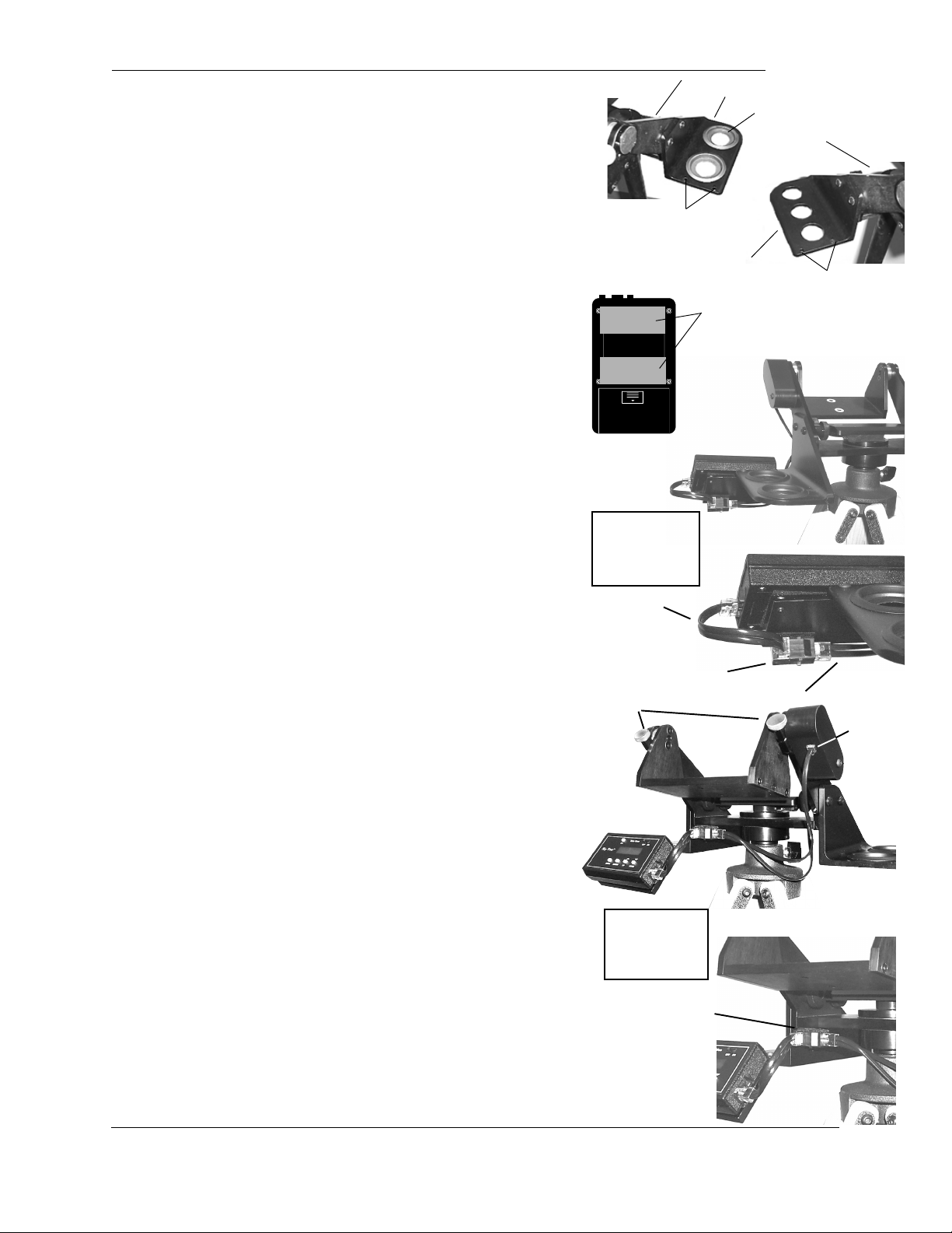
Sky Tour Caddy Plate Installation and Computer Attachment Sky Tour Caddy Plate Installation and Computer Attachment
7)
Sky Tour Caddy Plate Installation and Computer Attachment – The Sky
Sky Tour Caddy Plate Installation and Computer Attachment Sky Tour Caddy Plate Installation and Computer Attachment
Tour Caddy Plate attaches to either the left or right eyepiece caddy using the
two supplied button head screws and Allen wrench. Keep the two halves
of the Velcro strip together and stick one side on the back of your Sky Tour
computer as shown. Peel the remaining backing off of the Velcro and stick
the Sky Tour computer onto the Mounting Bracket.
Sky Tour Wiring ConnectionsSky Tour Wiring Connections
8)
Sky Tour Wiring Connections
Sky Tour Wiring ConnectionsSky Tour Wiring Connections
a) If the Sky Tour Caddy Plate is attached to the right Caddy, use the Velcro to
stick the Harness Junction Box to the back of the plate, in the lower right hand
corner. Orient the Box so that the Main Wiring Harness plugs straight in from the
left end of the box. The Pigtail Harness will then plug in from the front. Loop the
Pigtail around and plug it into the Sky Tour Computer.
or
b) If the Plate is attached to the left Caddy, use the Velcro to stick the Harness
Junction Box to the underside of the mount head, in the left corner, against
the left side Caddy Bracket. Orient the Box so that the Main Wiring Harness
plugs straight in from the right end of the box. The Pigtail Harness will then
plug into the Box directly toward you. Plug the other end into the Sky Tour
Computer.
Adjust the azimuth tension knobAdjust the azimuth tension knob
9)
Adjust the azimuth tension knob until there is a slight amount of tension.
Adjust the azimuth tension knobAdjust the azimuth tension knob
Place the cradle in approximately level position as indicated by the altitude
alignment marks (drilled hole on one of the side altitude bearings, forming
two semi-circles). Tighten the vertical tension knobs.
Telescope Attachment
Remove the Mounting PlateRemove the Mounting Plate
1a)
Remove the Mounting Plate supplied with the Tele Vue-NP127 from the
Remove the Mounting PlateRemove the Mounting Plate
Mount Ring Set. Fasten the Mounting Plate to the underside of the Cradle Base
Plate using the four ¼-20 button head screws supplied. Place the NP127 so the
studs and guide pins in the rings insert into the corresponding holes in the
mounting plate. Fasten with two Wing Nuts.
Mounting other Tele Vue TelescopesMounting other Tele Vue Telescopes
1b)
Mounting other Tele Vue Telescopes - If you own an NP127, leave the
Mounting other Tele Vue TelescopesMounting other Tele Vue Telescopes
Mounting Plate attached to the Gibraltar5 Cradle Base Plate. Thread the
supplied longer 1¼" studs into the telescope's ring mount. (If you do not own an
NP127, use the shorter 3/4" long studs.) Place the telescope down in the Cradle
so the studs go through the cradle holes. Note: orient telescope so Vertical
Tension Knobs are closer to the telescope's eyepiece end. Fasten in place with
plastic Wing Nuts.
Telescope Use
1) Place eyepiece in scope.
2) Apply slight and equal tension to altitude bearings using the altitude
bearing tension knobs.
3) Swing the scope up approximately 45° and check balance. If the scope
wants to swing back down, slide the scope back in the mount ring until
balance is achieved. If the scope wants to swing up, push it forward until
balance is achieved.
4) Apply more tension to achieve the desired feel. Extra tension can be used
to overcome a minor out-of-balance condition. However, excessive tension
will cause the movement to be “jerky.” Severe overtightening could strip the
threads in the mount head. Azimuth tension is pre-set at the factory and
should not be adjusted.
5) The most stable way of slewing your scope is by grasping a fixed part of the
telescope, (i.e., focuser body), mount head or (optional) mount handle. Slewing
the scope by holding the diagonal could cause slight image shift when you
release.
Computer Alignment
Please follow the alignment instructions on page 11 in the yellow Sky Tour
Operating Guide. Though the guide was originally written for the Gibraltar
Mount, all aspects of Sky Tour use apply to Gibraltar5 mounts.
Yoke Arm
Sky Tour
Bracket Holes
1¼" Eyepiece Caddy
Right handed installation on Sky Tour
Caddy Plate as
viewed from in front
of the mount
Pigtail
Close-up of junction box
location and orientation
Altitude Tension
Knobs
Left handed
installation on Sky
Tour Caddy Plate
as viewed from
behind the mount
Close-up of
junction
box location and
orientation
2" Eyepiece Caddy
1¼" Removable Insert
Yoke Arm
Velcro location on
back of Sky Tour.
Main Wiring Harness
Sky Tour
Bracket Holes
Altitude
Encoder
Jack
Tele Vue
Visionary
®
32 Elkay Dr., Chester, New York 10918 (845) 469-4551 televue.com
 Loading...