

Page 1
EYEPIECE CADDY SET INSTRUCTIONS
PARTS LIST
2" Eyepiece Bracket w. 1¼" plastic inserts
1¼" Eyepiece Bracket
(4) Thumb Knobs
INTRODUCTION
Thank you for purchasing the Eyepiece Caddy Set.
This versatile accessory attaches to the yoke arms of
your Tele Vue mount and places five eyepieces
conveniently at your fingertips. Also available is a plate
to attach the Sky Tour display unit. This plate will mount
to either Caddy, using the available clearance holes.
The Caddy Set is precision machined aluminum, and powder-coated for lifetime durability. You
may wish to remove them and pack separately when
carrying a mount head in luggage.
INSTALLATION
The most current yoke and cradle heads have the
attachment holes already drilled into the arms. If your mount arms
are not predrilled, you can use a drill press and the enclosed
templates to make the holes yourself.
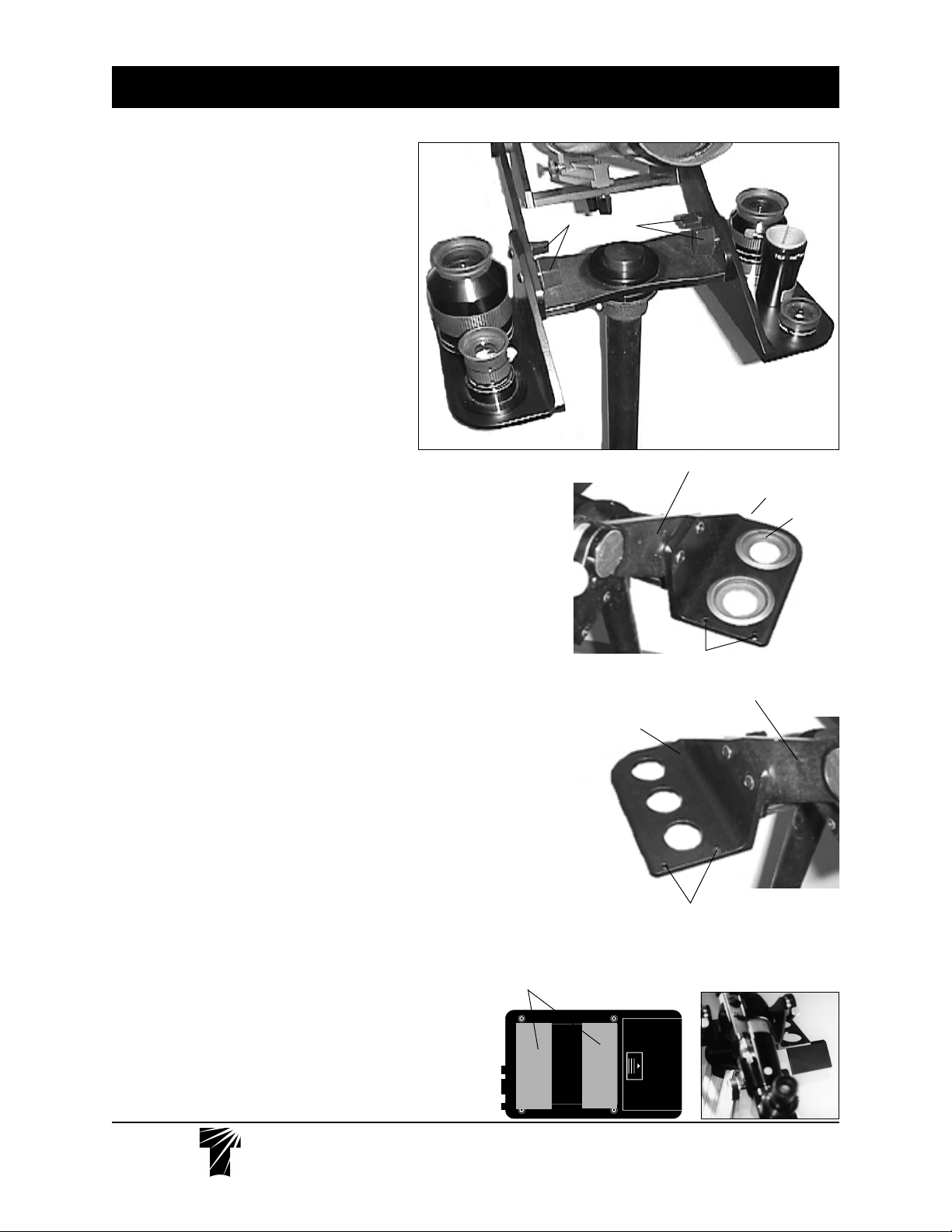
Attach each Caddy bracket by passing the screws through the
clearance holes in the yoke arms and tightening the thumb knobs.
The angled edge will match the arms, so that when viewing
from the telescope eyepiece position, the (3) 1¼" holes will be on
the left side, while the (2) 2" holes with removable 1¼" plastic plugs
will be to your right.
USE
You can place up to (5) 1¼" eyepieces in the Caddy Set, or by
removing the plastic inserts, use (3) 1¼" and (2) 2" eyepieces. To
remove the 1¼" inserts, push up from the bottom. To reinstall the
1¼" inserts, push them in from the top by running your thumbs
around the outer lip.
If you have dual barrel eyepieces you can use either 1¼" or
2" holes, but the outside lock screw in the 2" eyepiece barrel must be
removed.
Of course, your Barlow or Powermate units, or 2" to 1¼"
adapters can also be placed in the Caddy Set.
Optional Sky Tour Mounting Bracket
The optional Sky Tour Mounting Bracket attaches to either the left or
right eyepiece caddy using the two supplied button head screws
and Allen wrench. Keep the two halves of the Velcro strip together
and stick one side on the back of your Sky Tour computer as shown.
Peel the remaining backing off of the Velcro and stick the Sky Tour
computer onto the Mounting Bracket. When using shorter scopes
like our Tele Vue--76 or Tele Vue-85, make sure you leave enough
finger room between the computer and the focusser knob.
Thumb Knobs
Yoke Arm
2" Eyepiece Caddy
1¼" Removable Insert
Sky Tour
Bracket Holes
Yoke Arm
1¼" Eyepiece Caddy
Sky Tour
Bracket Holes
Velcro location
on back of Sky
Tour.
Te l e V u e
Visionary
®
32 Elkay Dr., Chester, New York 10918 (845) 469-4551 televue.com
INSTTEC-200
Page 2
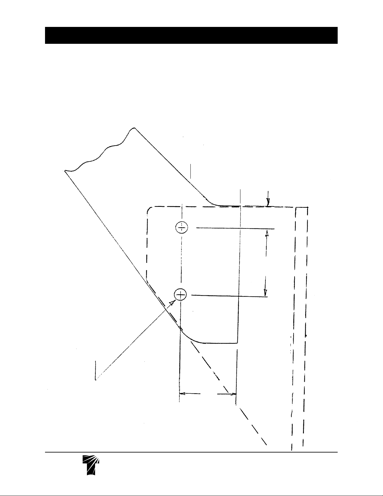
LEFT YOKE ARM TEMPLATE
EYEPIECE CADDY MOUNTING HOLE POSITIONS IN YOKE ARMS OF: PANORAMIC/GIBRALTAR/
UPSWING/TELEPOD HEADS
NOTE: Tele Vue strongly recommends using a drill press, not a hand drill for making these holes.
1) Transfer the measurements from the drawing to your Yoke arm.
Or, cut out the template and tape it to the outside of the Yoke arm, with the bottom and back surfaces
aligned with the corresponding surfaces of your yoke arms.
2) Center punch the holes to be drilled.
3) Secure the mount head so it won't move while drilling.
4) Drill the holes with a 17/64 diameter drill.
BACK SURFACE
BOTTOM SURFACE
ARM
Drill 17/64 dia. (2 pl)
If arms not pre-drilled
.50
1.50
1.25
Te l e V u e
Visionary
EYEPIECE CADDY
®
32 Elkay Dr., Chester, New York 10918 (845) 469-4551 televue.com
INSTTEC-598
Page 3

RIGHT YOKE ARM TEMPLATE
EYEPIECE CADDY MOUNTING HOLE POSITIONS IN YOKE ARMS OF: PANORAMIC/GIBRALTAR/
UPSWING/TELEPOD HEADS
NOTE: Tele Vue strongly recommends using a drill press, not a hand drill for making these holes.
1) Transfer the measurements from the drawing to your Yoke arm.
Or, cut out the template and tape it to the outside of the Yoke arm, with the bottom and back surfaces
aligned with the corresponding surfaces of your yoke arms.
2) Center punch the holes to be drilled.
3) Secure the mount head so it won't move while drilling.
4) Drill the holes with a 17/64 diameter drill.
1.25
Drill 17/64 dia. (2 pl)
If arms not pre-drilled
ARM
EYEPIECE CADDY
1.50
.50
Te l e V u e
Visionary
BOTTOM SURFACE
BACK SURFACE
®
32 Elkay Dr., Chester, New York 10918 (845) 469-4551 televue.com
INSTTEC-598
 Loading...