

Page 1
ENCODER INSTALLATION INSTRUCTIONS
PARTS LIST
Altitude Encoder Assembly includes:
(1) Altitude encoder
#10-32x3/8 Button Head
(1) Delrin encoder housing
Azimuth Encoder
#10-32x1-1/2 Button Head
Delrin Azimuth encoder housing/scope stop
Main Wiring Harness (2 to 1 connector)
Pigtail Harness
Harness Junction Box with attached Velcro
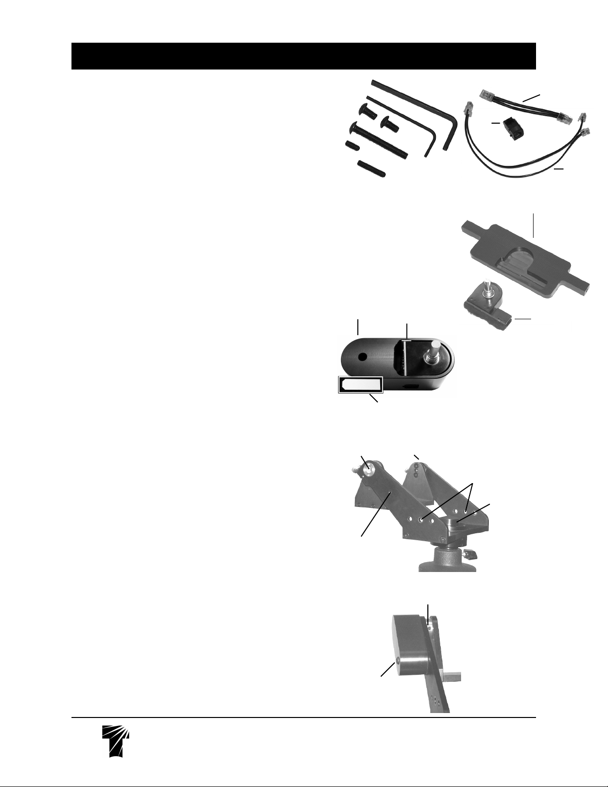
Parts Bag includes:
(2) #10-32x3/8 button head screws, (1) #10-32x1-1/2" button head
screw, (1) #8-32x3/8" set screw, (1) #8-32x3/4" set screw, (1) 5/64
Allen Key, (1) 1/8 Allen Key.
INTRODUCTION
Thank you for purchasing the encoder kit which will allow you to connect the Sky
Tour computer to your Tele Vue mount. An additional Spacer Kit, product code
STS-5002, is required for installation of the azimuth encoder onto a Gibraltar5
mount. Otherwise the kit is identical for all mounts and attaches in the same
manner. The ability to add digital setting circles to these mounts adds a new level
of versatility and convenience while allowing you to further your astronomical
repertoire.
ENCODER SET-UP
Altitude Encoder AssemblyAltitude Encoder Assembly
Altitude Encoder Assembly
Altitude Encoder AssemblyAltitude Encoder Assembly
There should be a yellow or pink plastic shim between the edge of the altitude
encoder circuit board and the inside of the encoder cover. It is needed to prevent
mechanical “play” of the encoder within the cover, which would reduce the
encoder’s accuracy. Friction should hold it in position (shown in the photograph,
right) during shipping, but if it has fallen out, reinsert it lengthwise, beveled-cornersend first.
1) Note alignment mark on top of left yoke arm (as seen standing behind the mount
head) Leave this altitude bearing alone
2) Using a utility knife blade, pry the name plate off the right side altitude bearing
cover. (As seen standing behind the mount head) This is the opposite bearing from
where the alignment marks are.
3) This will reveal 2 Allen key screws. Remove the screws and bearing cap with
the 5/64 Allen key.
4) Check the threaded hole in the right-side brass altitude bearing for a set-screw.
If no set-screw is found, use the #8-32x3/8" provided in the parts bag.
5) Make sure the plastic shim is still in place, then slip the shaft of the Altitude
Encoder Assembly fully into the hole in the center of the altitude bearing.
6) Using the 5/64 Allen key, tighten the set-screw against the encoder shaft.
7) Swing the Altitude Encoder Housing so the hole aligns with the threaded hole
in the Yoke Arm.
8) Thread the #10-32x1-1/2" button head screw into the hole to lock the Altitude
Encoder Assembly in place and snug up with the 1/8 Allen key. (No need to over
tighten.)
1/8 Allen Key
5/64 Allen Key
#8-32x3/8
Set Screw
#8-32x3/4
Set Screw
Contents of Parts Bag
Altitude Encoder
Assembly
Hole for Altitude
encoder
Screw hole for
#10-32x1-1/2"
button head screw
Plastic
Shim
Plastic Shim
Closeup
Alignment
Marks
#8-32x3/8" setscrew location
Parts not shown to scale
Pigtail
Junction
Box
Main
Wiring
Harness
Delrin Azimuth encoder housing/scope
stop (underside showing cutout for azimuth encoder)
Azimuth
Encoder
Screw holes for
Azimuth encoder
housing
Original
scope stop
Te l e V u e
Te l e V u e
Visionary
Visionary
#10-32x1-1/2"
button head
screw
32 Elkay Dr., Chester, New York 10918 (845) 469-4551 www.televue.com
32 Elkay Dr., Chester, New York 10918 (845) 469-4551 www.televue.com
OVER
Page 2
Azimuth Encoder AssemblyAzimuth Encoder Assembly
Azimuth Encoder Assembly
Azimuth Encoder AssemblyAzimuth Encoder Assembly
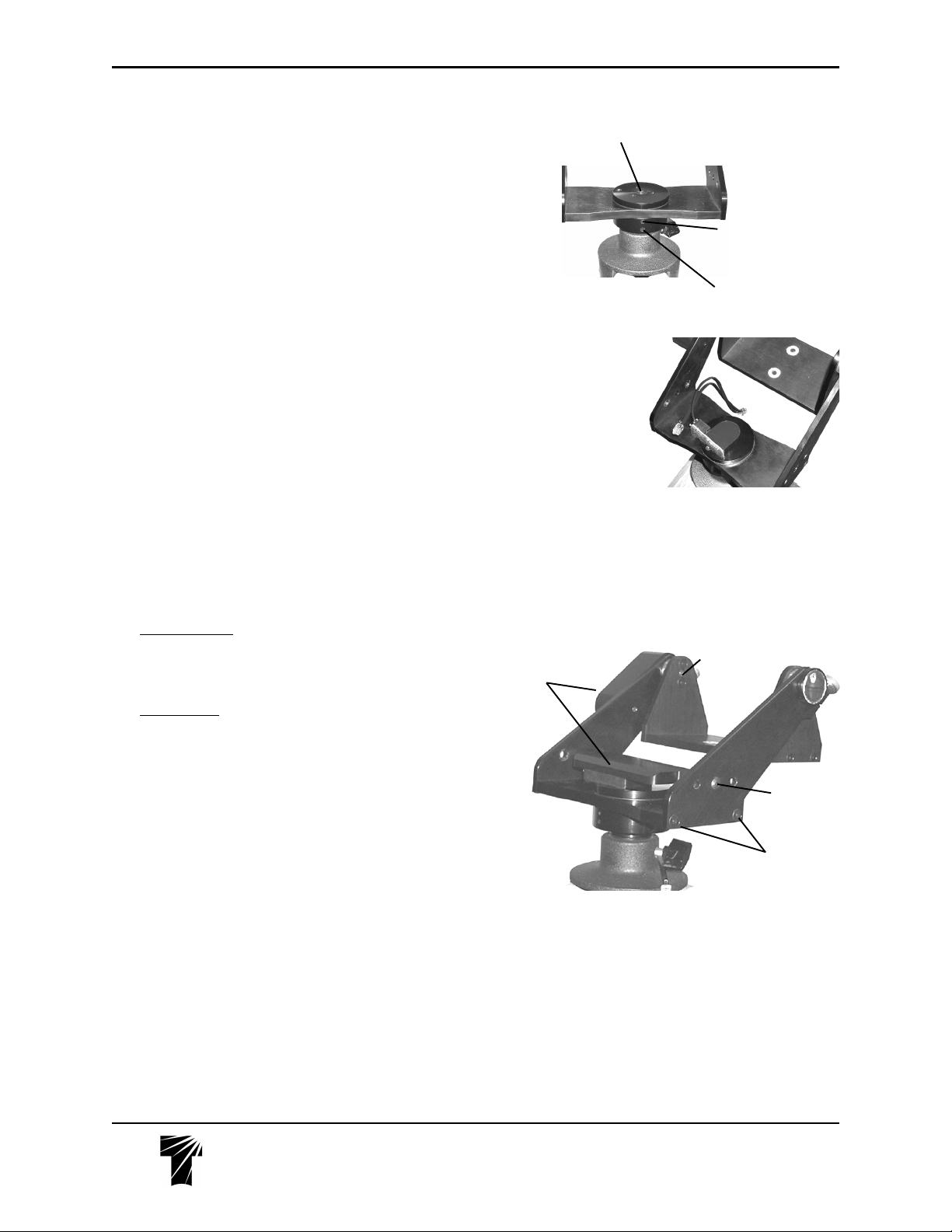
9) On the Yoke, unscrew both the original Delrin Scope Stop and Azimuth
Tension Knob from the center of the azimuth bearing.
10) Check the upper threaded hole in the lower azimuth bearing base for a setscrew. If no set-screw is found, use the #8-32x3/4" provided in the parts bag.
11) Connect the azimuth lead of the Main Wiring Harness to the Azimuth
Encoder.
12) Press the Azimuth Encoder shaft down into the hole in the center of the
azimuth bearing.
13) With the 5/64 Allen key, lock the set-screw against the az. encoder shaft.
14) Rotate the encoder so the wiring harness terminal faces the Altitude Encoder
and route the remaining terminals out the back of the Yoke, under the cradle.
(See photo , right.)
15) Loosen both of the 10-32x1/2” flat head screws which hold either of the
yoke arms onto the base plate a couple of turns (it doesn’t matter which arm).
Slide the Azimuth Encoder Cover down between the Yoke Arms so that the
screw holes line up with the middle of the three clearance holes in the Yoke
Arms. The Azimuth Encoder Cover will fit only one way over the Azimuth
Encoder: make sure the encoder is aligned properly with the recess in the cover
before pressing it on. Do not force the cover onto the encoder; the encoder will
have a snug fit into the cover cut-out.
If it is too difficult to achieve this alignment, remove the encoder (see the section
on Removing and Reinstalling encoders), insert the encoder body into the recess
in the cover and attempt to install the encoder and cover as a unit. Again, do not
force the encoder. Retighten the set screw.
16a)
Gibraltar5 mounts: place the spacers from the STS-5002 kit between the
ends of the Delrin azimuth bar and the insides of the yoke arms. Thread the 1032x1¼” button head screws provided in the kit into each side to hold the
Azimuth Encoder. Continue with step 16c.
16b)
All other mounts: thread a 10-32x3/8 button head screw into each side
to hold the Azimuth Encoder Cover in place. Continue with step 16c.
16c) Tighten button head screws with the 1/8 Allen key while pressing down
on the cover. Once the cover is in place and the appropriate button head
screws are threaded a few turns into the ends of the arms of the encoder cover,
retighten the flat head screws on the yoke arm until they just barely bottom out.
Do not tighten them yet.
Hook a finger under one arm of the azimuth cover and pull it up (away from the
base plate) while tightening its round head screw. Repeat with the other arm.
Retighten the flat head screws the rest of the way.
17) Connect the altitude lead of the Main Wiring Harness to the Altitude
Encoder.
Original scope stop removed,
reveals hole for Azimuth Encoder
Azimuth encoder in
position. Note how
Main Wiring Harness is draped
through the Yoke
and Cradle
Both encoder
assemblies
installed.
Screw hole for
#8-32x3/4" set screw.
Screw drops in, threads
start deep within the hole.
Screw hole for Panoramic
attachment post
End of Altitude
Encoder Shaft
#10-32x3/8"
button head screw
(or #10-32x1¼"
for Gibraltar5)
#10-32x1/2"
flat head screws
If you have the Eyepiece Caddy Set, skip instruction 18 and follow the
instructions in the next section.
18) If you do not have the recommended Eyepiece Caddy Set with the Sky
Tour Mounting Plate, connect the remaining lead of the Main Wiring Harness
to the Sky Tour Computer.
19) Follow the instructions provided with the Sky Tour for computer operation.
Te l e V u e
32 Elkay Dr., Chester, New York 10918 (845) 469-4551 www.televue.com
Visionary
CONTINUED NEXT PAGE
Page 3

USE WITH SKY TOUR CADDY PLATE
The Sky Tour Caddy Plate conveniently places the Sky Tour Computer at
your finger tips, while the Eyepiece Caddies hold your eyepieces. These
are especially useful for Tele-Pod owners, and are a standard feature of the
factory mount / Sky Tour package.
20) Attach Caddy Brackets to each of the Yoke Arms as per the supplied
instructions
21) Attach the Sky Tour Caddy Plate to the preferred Caddy Bracket as per
the supplied instructions.
22a) If the Plate is attached to the right Caddy, use the Velcro to stick the
Harness Junction Box to the back of the plate, in the lower right hand corner.
Orient the Box so that the Main Wiring Harness plugs straight in from the left
end of the box. The Pigtail Harness will then plug in from the front. Loop the
Pigtail around and plug it into the Sky Tour Computer.
22c) If the Plate is attached to the left Caddy, use the Velcro to stick the
Harness Junction Box to the underside of the mount head, in the left corner,
against the left side Caddy Bracket. Orient the Box so that the Main Wiring
Harness plugs straight in from the right end of the box. The Pigtail Harness
will then plug into the Box directly toward you. Plug the other end into the Sky
Tour Computer.
REMOVING and REINSTALLING ENCODERS
IMPORTANT: Once the encoders are pushed into place, they cannot be
pulled out. Do NOT attempt to pull up or pry them out. They will break.
Instead, they need to be tapped out from the end of the 1/4" diameter
encoder shaft. Spread a towel or some other thick fabric over the work
surface and any part of the head that an encoder may hit once it has been
pushed free. Use an Allen key or small screwdriver as a "drift" (spacer) to
tap against.
1) Remove the button head screw(s) holding the respective encoder cover
in place.
2) Loosen the respective encoder shaft set-screw.
3a) Altitude Encoder - Place the drift against the end of the encoder shaft,
as seen in the bottom photo on the prior page. Tap lightly with a hammer to
dislodge the encoder
3b) Azimuth Encoder - The head must be removed to stick drift into the
3/8" hole in the middle of the underside of the Azimuth bearing. Follow
removal instructions below.
Tele Pod mount: the Quick Release Base must be removed by loosening
both the lower set screw in the bottom disc of the azimuth bearing and the
small set screw in the underside of the Quick Release Base’s flange, and
unscrewing the base.
Panoramic mount: the attachment post must be removed by loosening the
set screw and unscrewing the post until it comes off.
Gibraltar or Gibraltar5 mount: the mounting stud must be removed by
loosening the lower set screw in the bottom disc of the azimuth bearing and
unscrewing the stud.
Right handed installation on Sky Tour
Caddy Plate as
viewed from in front
of the mount
Pigtail
Close-up of junction box
location and orientation
Main Wiring Harness
Altitude
Encoder
Jack
Left handed
installation on Sky
Tour Caddy Plate
as viewed from
behind the mount
Close-up of junction box
location and orientation
Te l e V u e
Visionary
32 Elkay Dr., Chester, New York 10918 (845) 469-4551 www.televue.com
 Loading...