

Page 1
®
--
Te l e Vue
-102
--
iis
Operating Guide
880mm f/8.6 IMAGING SYSTEM
2-ELEMENT APO REFRACTOR
Thank you for purchasing the Tele Vue-102iis. It has been our pleasure to craft this fine instrument for
you and we hope that it serves you well.
The original Tele Vue-102i used a Tele Vue-102 objective with a tube cut 5” shorter. Removing 5” of
mechanical path length allowed the Tele Vue Bino Vue (hence the “2i” designation) to be used at 1x.
Recognizing the additional back focus of the 102i could be a great benefit to photographers, we created
an Imaging System version, the Tele Vue-102iis.
Tele Vue’s “
photographic accessories. Tele Vue has designed this series of accessories in conjunction with each optical
system so you are ensured of compatibility and maximum performance. While the 102iis maintains all the
visual performance and versatility of the standard Bino Vue ready Tele Vue-102i, the larger focuser along
with a host of proprietary Imaging System accessories, make it ideally suited for the CCD imager.
isis
is” designation denotes Tele Vue instruments capable of accepting
isis
II
Imaging
II
SS
System
SS
WARNING: NEVER try to look at the sun or point the telescope toward or near the sun without
professional solar observing equipment rigidly secured in front of the objective lens. When
observing the sun with the proper filters, remove any finding devices such as Starbeam from the
telescope. Instant and permanent eye damage may result from viewing the sun directly, even during a solar
eclipse, or when viewing through thin clouds, or when the sun is near the horizon.
Standard FeaturesStandard Features
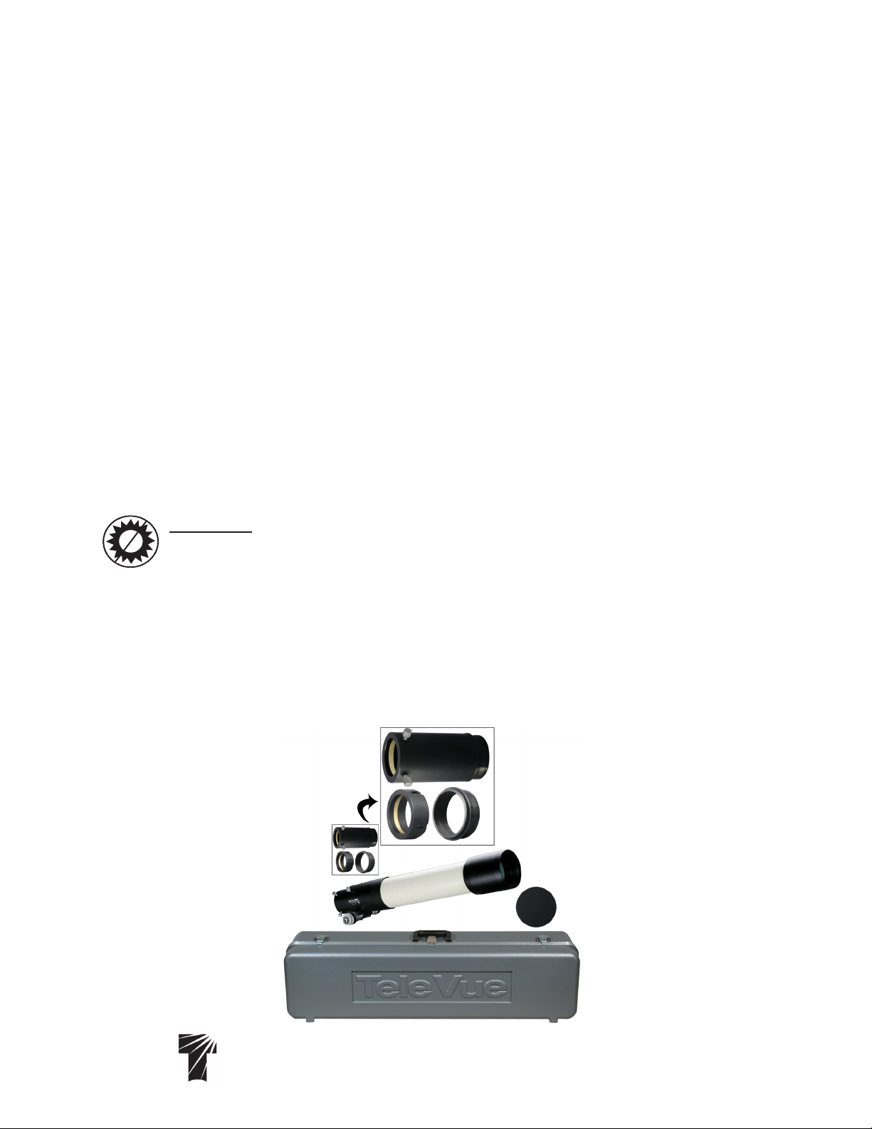
Standard Features - Optical tube assembly includes: captive sliding dew shield, 2.4” focuser with
Standard FeaturesStandard Features
Focusmate 6:1 reduction, tilt adjustment end ring, screw-on metal lens cover, 5” Extension Tube for single
eye observing, 2” Accessory Adapter, Imaging System Adapter, custom hard-shell case, Allen Keys for end
ring tilt adjustment.
5” Extension Tube
2” Accessory Adapter (left)
Imaging System Adapter (right)
Optical Tube Assembly
Lens Cap
Te l e V u e
Visionary
Case
®
32 Elkay Dr., Chester, New York 10918 (845) 469-4551. televue.com
1
Page 2
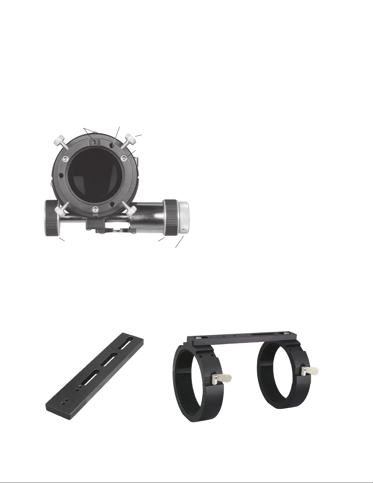
1.0 Getting Acquainted with the Tele Vue-102iis
1.1 Optical tube assembly
The OTA consists of the objective cell, tube and focuser. The front cell houses the carefully aligned
objective. Never attempt to loosen the 3 alignment screws in the front lens cell. The tube is aluminum and
powder coated, requiring no special care.
The focuser on the
102iis102iis
102iis permits use of a larger draw tube that does not vignette the field rays exiting
102iis102iis
the objective. The two tension screws (not shown) on the top of the focuser body can be adjusted to add
resistance when using heavy equipment. These tension screws tighten against a brass clamp ring, which
then cinches down on the Teflon sleeve in which
Digital Indicator
Mounting Points
Jack Screws (typical)
Lock Screws (typical)
the draw tube slides. For photography it is not
necessary to tighten beyond the need to keep a
camera stationary but we do recommend to
tighten them in unison to avoid any focus shift.
Jam Screws (typical)
Note that even when sufficiently tight, the focuser
knobs can still drive the draw tube.
The end ring can be adjusted (and locked)
to compensate for any tilt effects seen in CCD
imaging.
The threaded holes on top of the focuser
body accept the Digital Indicator Kit.
The four lock screws in the end of the
draw tube tighten against either the tapers of the
Imaging System Adapter and 5” Extension Tube,
or brass clamp ring within the 2” Accessory
1:1 Knob
1:1 Knob
6:1 Knob
Adapter.
Operation of the rack and pinion focuser
is via the 6:1 ratio Focusmate on the right side or either of the 1:1 knobs.
2.0 Mounting and Set Up
The MRS-4000 ring set is recommended for the Tele Vue-102iis. Note that the short main tube of this “Bino
Vue” friendly scope design requires extension tubes for single-eye viewing or for imaging applications. This
results in a “rear heavy” scope that may also require the APL-1096 “Long Balance Plate” accessory in order
to move the scope forward enough to achieve balance. The plate attaches directly to the AVT-1011 adapter
for all Vixen equatorial mounts, or directly to the cradle of our Gibraltar 5 head for alt-az visual operation.
The center of gravity is moved forward to avoid the need for balance weights at the front of the tube.
APL-1096 - can be used under the tube
ring to shift the telescope weight forward
to help balance should it be necessary.
MRS-4000 - Heavy duty tube ring set with
slotted spreader bar to adjust ring spacing
for a wide variety of equatorial mounts.
2
Page 3
The rings have grooves with #10-32 screw holes for attaching accessories such as the Tele Vue
Starbeam or Piggy-Cam. A central bar spans across the top of the two rings and permits varying the spacings
between the rings in order to fit a variety of mount heads.
The bottom of the rings have ¼-20 threaded holes to accept mounting studs or screws. Telescope
balance is achieved by unlocking the “bat handle” screws and sliding the tube fore or aft. Once
repositioned, retighten the bat handle screws.
3.0 Visual Observing Set Up
The versatile 102iis can be set up in two configurations for visual observing: two eye viewing with the Bino
Vue as in the previous 102i model, and single eye which permits both 1¼” and 2” eyepiece use. The
optional components necessary include a Tele Vue 2” Everbrite Star Diagonal, Tele Vue “High-Hat” 2”- 1¼”
reducing adapter, Tele Vue Bino Vue Body and eyepieces. For daytime viewing with Bino Vue see 3.0A.
The telescope is delivered with the 2” Accessory Adapter already installed in the focuser. To remove
it, back out the four lock screws and pull it out. To reinstall it, note
the four grooves with holes machined 90° apart. The grooves will
help index the holes in the adapter to the thumb screws in the end
ring. This will ease installation in the dark. Loosen the four end ring
lock screws sufficiently to remove any accessory that may be in
place, but do not retract them fully into the focuser body. By
allowing them to protrude into the body, they act as locators.
Insert the 2” Accessory Adapter into the end of the
focuser. If it does not go all the way in, rotate the
adapter. When the grooves in the adapter align
with the protruding screws, the adapter will seat
fully into the focuser. Tighten the four screws a few
turns so they enter the holes in the adapter. The
Insert the 2” Accessory Adapter into the 2.4” focuser for
Bino Vue use.
IMPORTANT CAUTION:IMPORTANT CAUTION:
IMPORTANT CAUTION: When replacing the orange plastic plug into the 2” Accessory Adapter, push it
IMPORTANT CAUTION:IMPORTANT CAUTION:
in far enough to seat. Do
notnot
not use the lock screws to clamp the plug in place as the clamp screws will distort
notnot
lock screws will now act against the brass clamp
ring in the 2” Accessory Adapter.
the brass clamp ring in the 2” accessory adapter.
3.0A Bino Vue Set Up 3.0A Bino Vue Set Up
3.0A Bino Vue Set Up - To use the scope with the Bino Vue, install the 2” Accessory Adapter. Slip a Tele
3.0A Bino Vue Set Up 3.0A Bino Vue Set Up
Vue 2” Everbrite diagonal into the focuser and tighten the lock screws. Insert the High-Hat adapter and then
the Bino Vue into it. Remember to remove the 2x amplifier if it is installed on your Bino Vue. To maintain the
performance of the telescope at the highest magnifications, use the Bino Vue Prism Corrector (BPC-0007).
For comfortable daytime viewing, we recommend the 60° 1¼” Everbrite diagonal. This configuration
requires the ACF-2125 Flat-Top 2”-1¼” adapter be used in place of the “High-Hat” type adapter.
3.0B Single Eye Viewing3.0B Single Eye Viewing
3.0B Single Eye Viewing - In order to achieve enough back focus to use the Bino Vue at 1x, five inches was
3.0B Single Eye Viewing3.0B Single Eye Viewing
cut off the telescope tube of the standard 102. To reach focus with single eye viewing we need to add that
length back via the extension tube provided standard with the 102iis. This special extension tube has the
large Imaging System adapter on one end and a 2” inside diameter on the other. Simply insert the extension
tube into the focuser end ring and tighten the four screws. Slip a Tele Vue 2” Everbrite diagonal in to the
extension tube and tighten the two lock screws. You can now use 2” Tele Vue eyepieces. Add the High Hat
adapter to use 1¼” eyepieces.
3.1 Eyepieces
With a range of 16x to 250x or more (if the atmosphere allows), Tele Vue eyepieces provide a magnification
for all purposes. See the chart at the end of this manual or call Tele Vue for recommendations. In general,
we suggest choosing low and medium power eyepieces in ratios of field stop diameters. For example,
factors of 1.4 or 2.0. When choosing higher power eyepieces, use ratios of magnification. (see reference
chart in “Choosing Your Eyepieces”)
3
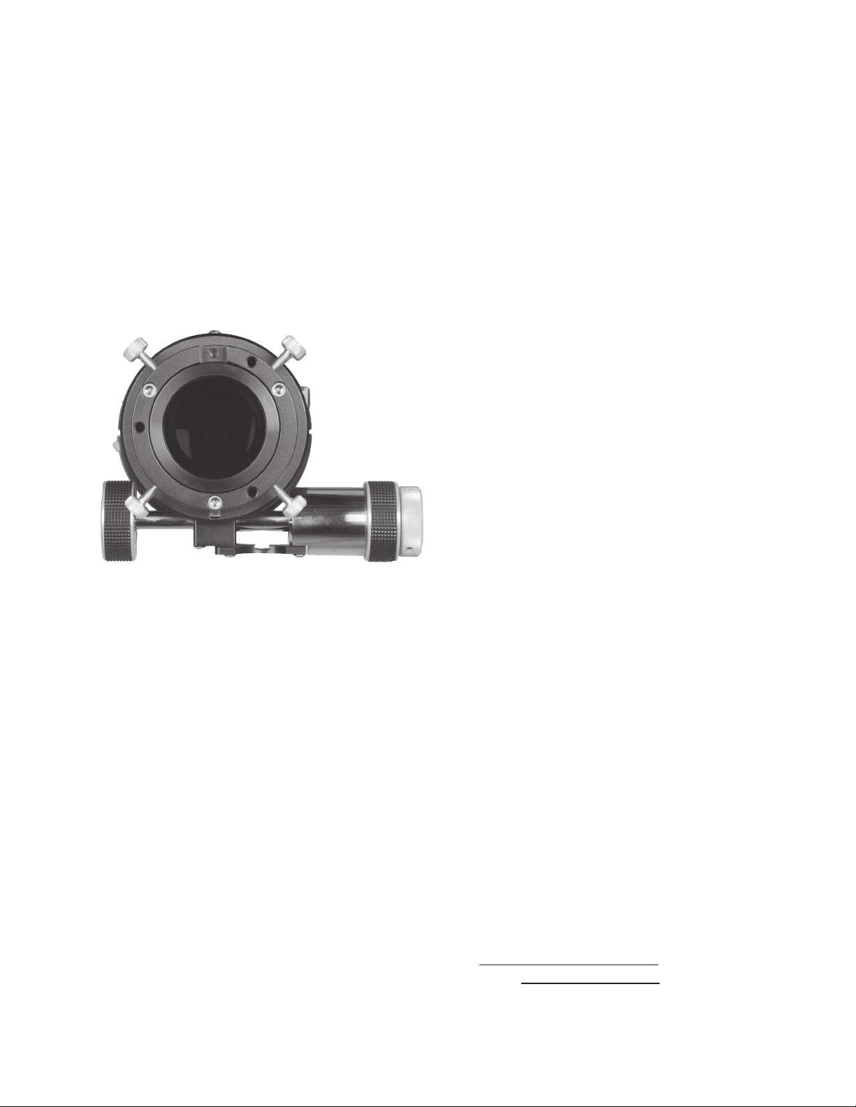
Page 4

Focuser with Imaging System Adapter in place.
3.2 Finders
We particularly recommend using the Starbeam reflex sight (part# SFT-1003), which
attaches to the Tube Rings. The case has a
cutout for the Starbeam. The Quick Release
Universal Finder Bracket (QFM-1008) can
hold a traditional 50mm finderscope and also
attaches to the mount ring channels.
4.0 Photographic Set Up and the Tele
Vue Imaging System
Using the 102iis for photography begins with
the insertion of the included Imaging System
adapter into the focuser. From that threaded
connection, the Imaging System accessories
provide a variety of options for camera adaptation and focal length variation. The goal of the
imaging system is to let you pursue your
astrophotographic passion with ease. The
following summary of parts and pictorial diagram will help you understand each part’s use
and its sequence in the chain. Please note that
spacing requirements of any particular camera
will need to be met by the appropriate Imaging
System spacer or combination of spacers.
The 2.4” focuser and
Imaging System
accessories are robust
enough to solidly hold
the heaviest CCD
equipment.
RFL-4087RFL-4087
RFL-4087 0.8X Field Flattener
RFL-4087RFL-4087
• Optimizes edge of field performance
while shortening the effective focal length to
704mm for more field of view, and changing
the focal ratio to f/6.9.
STL-1071STL-1071
STL-1071 – SBIG STL series camera adapter
STL-1071STL-1071
• This adapter is sized to thread directly
onto the STL series cameras and mates with
Imaging System accessories.
TRG-1072TRG-1072
TRG-1072 – Standard T-ring adapter
TRG-1072TRG-1072
• This is the most restrictive of adapters as it
has the smallest inside diameter. Recommended for use with APS size or smaller chips.
CWT-2070CWT-2070
CWT-2070 – Canon Wide T Adapter
CWT-2070CWT-2070
• Mates Canon T-rings with Imaging System Accessories.
• Eliminates the inner portion of Canon Trings to provide a larger diameter opening for
reduced vignetting.
A2A-1107A2A-1107
A2A-1107 – 2” Accessory Adapter
A2A-1107A2A-1107
• Use for cameras with 2” nosepiece or any
other 2” accessory.
• Dual thumb-screws and clamp ring for
positive locking.
4
Page 5

TLX-1108TLX-1108
TLX-1108 – SCT Type Thread for filter wheel housings such as the True Technology Custom Wheel
TLX-1108TLX-1108
AFT-1105AFT-1105
AFT-1105
AFT-1105AFT-1105
–48mm Filter adapter
• Allows use of 48mm filters in the system.
• Best if used closest to the chip to minimize any vignetting
• Adds 0.25” of spacing.
TLE-1076TLE-1076
TLE-1076 – 3.8” (96.5mm) Length Spacer
TLE-1076TLE-1076
• This spacer is placed between the Imaging System Adapter and the 0.8X Field Flattener. It is
required for photography.
Focuser Features
A. Large Focuser for TV102iis, NP101is and NP127is
Standard features (A) include:Standard features (A) include:
Standard features (A) include:
Standard features (A) include:Standard features (A) include:
•Drawtube with 3" entrance aperture, 2.4" exit aperture
•End-ring with tilt capability
•4-Lock knobs to secure camera equipment or 2" adapter
•Body has brass clamp ring with 2 lock knobs
•Focusmate 6:1 dual speed focuser
•Indexed 2" accessory adapter for 1x Bino Vue use
•5" length extension tube for single eye viewing
•Imaging insert threaded for imaging system components.
Accessories (optional)
B. LMK-2404/LMF-2405 Digital Indicator Kit for Large Focuser
C. DSF-8002 2" Everbrite Star Diagonal (Bino Vue configuration)
D. FDU-2003 Focusmate Driver electronic vari-speed motor control.
(FDL-2002 required for Tele Vue Alt-Az mounts)
E. TLE-1076 3.8" long threaded extension for photography
F. RFL-4087 0.8x Reducer/Flattener for Tele Vue-102
G. AFT-1105 48mm Filter Adpater/0.250" long extension
H. AD2-1110 Apogee U47 D2/Yankee Robtic adpter
I. AD7-1111 Apogee U9000/U16 D7/D9 adapter
J. STL-1071 SBIG STL11000 Adapter
K. TRG-1072 Standard T-Ring adapter
L. CWT-2070 Canon Wide T Adapter
M. A2A-1107 - 2” Nosepiece Accessory Adapter
N. TLX-1108 - SCT Threaded Accessory Adapter
O. TLA-0250 0.250” long threaded extension
P. TLB-0375 0.375" long threaded extension
Q. TLC-0500 0.500" long threaded extension
R. TLD-1000 1.000" long threaded extension
5
Page 6

TLA-0250TLA-0250
TLA-0250 – 0.250" (6.4mm) Spacer
TLA-0250TLA-0250
TLB-0375TLB-0375
TLB-0375 – 0.375" (9.5mm) Spacer
TLB-0375TLB-0375
TLC-0500TLC-0500
TLC-0500 – 0.500" (12.7mm) Spacer
TLC-0500TLC-0500
TLD-1000TLD-1000
TLD-1000 – 1.000" (25.4mm) Spacer
TLD-1000TLD-1000
TLF-0040TLF-0040
TLF-0040
TLF-0040TLF-0040
TLG-0080TLG-0080
TLG-0080
TLG-0080TLG-0080
TLS-2245TLS-2245
TLS-2245 – Set of all six spacer rings.
TLS-2245TLS-2245
– 0.040" (1mm) Spacer
– 0.080" (2mm) Spacer
• Threaded coupling provides the necessary distance for proper spacing of field lenses to chip.
Required spacers will vary depending on camera specifications. 0.040” and 0.080” rings fit between
the threaded spacers.
• Black anodized aluminum with anti-reflection threads for maximum contrast.
4.1 Adjustable Position End Ring
The tilt of the End Ring to the optical axis can be changed to compensate for any tilt errors you may see in
your photography. The telescope is aligned with the End Ring locked firmly against the end of the draw tube.
In this way you are always assured of a reference point to return to if necessary.
To determine which way to tilt the End Ring, it is necessary to focus on the part of the image that comes
to focus first when racking out the focuser from its “in” position. That will permit adjusting, or “jacking,” the
End Ring “out” to match that focus point in the field.
You will need to remove your camera equipment, including the Imaging System Adapter to adjust the
tilt of the End Ring . Slightly loosen the three Jamb Screws located on the face of the End Ring with the
appropriate Allen key. Then, “jack” the End Ring to the desired position using the appropriate Allen key Jack
Screws. Tighten the Jamb Screws against the End Ring and reinstall your camera. Some trial and error
imaging will be necessary, so it is best to carry out any necessary adjustment during an imaging session.
4.2 Prime Focus
Prime focus photography involves attaching a camera, without its lens, to the telescope. In this method the
telescope becomes the camera’s lens. In the case of the 102iis, its native 880mm focal length, f/8.6
dednemmoceR
mumixaM
mlif/DCC
lanogaid
1mm01otpU6.8/fmm088°56.0
2
3
mm04
seiresLTSGIBS(
)saremac
mm04
saremaCRLS(
mm53otpu
)tamrof
deepShtgneLlacoFweiVfodleiF
9.6/fmm407°3.3
9.6/fmm407°3.3
Accessories Key
A. Imaging System Adapter (Supplied Standard)
TLE-1076TLE-1076
E.
TLE-1076 - 3.8” long threaded extension for photography
TLE-1076TLE-1076
RFL-4087RFL-4087
F.
RFL-4087 - 0.8x Reducer/Flattener
RFL-4087RFL-4087
TLA-0250TLA-0250
G.
TLA-0250 0.25" long threaded extension
TLA-0250TLA-0250
STL-1071STL-1071
H.
STL-1071 SBIG STL series adapter
STL-1071STL-1071
sucoFemirPtaecnamrofrePpoTrofsnoitadnemmoceRtnenopmoC
aremaC
rotcennoC
gnir-T
)2701-GRT(
ro
gniR-TediW
)0701-TWC(
seireSLTSGIBS
)1701-LTS(
gnir-T
)2701-GRT(
ro
gniR-TediW
)0702-TWC(
TRG-1072TRG-1072
I.
TRG-1072 Standard T-Ring adapter
TRG-1072TRG-1072
CWT-2070CWT-2070
J.
CWT-2070 Canon Wide T Adapter
CWT-2070CWT-2070
TLB-0375TLB-0375
K.
TLB-0375 0.375" long threaded extension
TLB-0375TLB-0375
TLC-0500TLC-0500
L.
TLC-0500 0.500" long threaded extension
TLC-0500TLC-0500
TLD-1000TLD-1000
M.
TLD-1000 1.000" long threaded extension
TLD-1000TLD-1000
lanoitiddA
otrecapS
mm55hctam
ecnerefer
XX
"57.0
0520-ALT)1(
0050-CLT)1(
X
6
sneLyrosseccA
X8.0
renettalF/recudeR
)7804-LFR(
X8.0
renettalF/recudeR
)7804-LFR(
htgnelrecapS
resucofmorf
ebutward
"8.6
0001-DLT)3(
6701-ELT)1(
"8.4
0001-DLT)1(
6701-ELT)1(
"8.4
0001-DLT)1(
6701-ELT)1(
Page 7

1. Prime focus for up to 10mm diagonal chips in
cameras with 55mm chip to T-Ring distance.
2. Prime focus with SBIG STL series cameras
3. Prime focus with 35mm format SLRs in cameras with 55mm chip to T-Ring distance.
specifications are changed to 704mm and f/6.9 respectively with the use of the 0.8x field flattener/
focal reducer is used. It is the focal length of the telescope in combination with the diagonal dimension
of the CCD chip or film frame that will determine the amount of field your photograph will cover. The
shorter the focal length or larger the diagonal dimension, the greater the field that will be recorded.
The recommendations below and in the diagrams are specifically for SLR (digital or film) and the
SBIG 11000 cameras. If you have a different camera, you will need to determine the spacer necessary
to achieve the optimal distance from the end of the T-ring adapter to the your CCD chip. This spacer
will be added in front of the T-ring adapter.
To start, you need to know the distance from the chip to the faceplate of the camera. This should be
specified in the camera’s documentation; call your camera’s manufacturer if it is not. The equation is simply
2.2” - Chip to faceplate distance = additional spacer length required. There is enough tolerance in this value
that using the Imaging System spacers which bring you as close as possible will work fine.
Since there are tolerances in all manufactured parts, it may be necessary to vary the spacing
slightly from the nominally calculated value. Should your star images in the the four corners look slightly
elongated, try using the next smallest increment of threaded spacer with either the 0.040” (TLF-0040),
2mm (TLG-0080), or both inbetween the threaded spacers to fine tune the image.
7
Page 8

5.0 ADDITIONAL ACCESSORIES
5.15.1
Digital IndicatorsDigital Indicators
5.1
Digital Indicators - All Tele Vue telescopes with rack and pinion focusers now permit the
5.15.1
Digital IndicatorsDigital Indicators
photographer to index focus position to within 0.0005” by means of a digital indicator. Mounting
points are provided on top of the focuser body and end of the draw tube for easy installation of the
various Digital Indicator Kits. Using the Digital Indicator provides a convenient way of finding best
focus, returning to it, or checking that it hasn’t changed.
Choose either the 10 Micron (0.0004") Indicator Kit (LMK-2404) or the 1 micron Indicator Kit (LMF-2405)
depending on the accuracy desired. Both indicators have 0.5" motion ranges and accept an RS-232
output cable for displaying readout on computer. The 10 foot long RS-232 Output Cable (RSC-2320)
permits remote indicator readout on computer screen via down-loadable software from the Tele Vue
website (www.TeleVue.com). The cable also provides power to the indicator.
5.25.2
Focusmate DriverFocusmate Driver
5.2
Focusmate Driver - (FDU-2003) This accessory electronically drives the fine focus knob of the
5.25.2
Focusmate DriverFocusmate Driver
Focusmate in steps of approximately 0.0005" per button click. With the button depressed, the motor
drives the Focusmate continuously without vibration transferred to the system. Motor speed is variable.
The motor has a standard phone jack that will accept a cord of any length. Remote control is possible.
Contact Tele Vue for further details.
6.0 Caring for your 102iis
The Tele Vue-102iis requires no special care. Treat it as you would any fine camera lens. Use the lens cap
when the telescope is being stored or not in use. The captive dew shield provides protection from glare,
helps protect the lens from dust or spray blown in by the wind and minimizes dew formation on the lens.
If dew forms on the lens during cold weather, it is best to use a hair dryer (on the lowest setting) to gently
warm it away. A few specks of dust will have no effect on image quality and may be gently blown off with
a squeeze bulb.
Do not use compressed air cans to blow dust off optical surfaces.Do not use compressed air cans to blow dust off optical surfaces.
Do not use compressed air cans to blow dust off optical surfaces.
Do not use compressed air cans to blow dust off optical surfaces.Do not use compressed air cans to blow dust off optical surfaces.
Fingerprints, however should be cleaned off. Though the anti-reflection coatings are durable, they are
easily scratched. The simplest cleaning method is to moisten (not soak) a very soft, lint-free tissue, cloth, “QTip” or surgical cotton with a lens or glass cleaner and gently whisk away the stain. Do not apply any
solutions directly to the glass surfaces. After every cleaning stroke, use a fresh applicator. The fewer strokes
the better! Any residual “film” will not affect visual performance.
Collimation of your Tele Vue-102iis has been locked at the factory. With reasonable care it will remain
aligned. However, rough handling can cause misalignment. WARNING: Do not loosen the button head
screws in the front lens cell as this will cause misalignment. If necessary, contact Tele Vue for re-collimation.
The tube is powder-coated for durability and needs no maintenance. Black anodized surfaces can be
cleaned with Windex. If you have any questions about the care, operation or performance of your Tele Vue102iis102iis
102iis, please call us at (845) 469-4551 from 9:30 am to 5:00 pm EST.
102iis102iis
7.0 Warranty
Tele Vue telescopes are warranted to be free of manufacturing or workmanship defects for 5 (five) years from
the date of purchase, to the original owner. Please return the warranty card as validation of your ownership
and for easy identification. If your Tele Vue telescope requires warranty service, please call Tele Vue to
discuss the problem, upon which you will receive a return authorization. NO RETURNS ARE
ACCEPTED WITHOUT PRIOR AUTHORIZATION.
The warranty does NOT include: collimation, defects caused by mishandling, defects of subjective
nature, coverage for any telescope purchased through an unauthorized Tele Vue dealer, or purchased
outside the home country where Tele Vue has representation.
Warranty work will be performed at Tele Vue’s discretion and may only be performed by Tele Vue
Optics. The telescope must be shipped in its case with proper inner and outer packaging. Return shipping
and insurance charges are the purchaser’s responsibility.
8
Page 9

Tele Vue recommends choosing low and medium power eyepieces in ratios of field stop diameters. For
example, factors of 1.4 or 2.0. When choosing higher power eyepieces, use ratios of magnification.
Tele Vue-102/102iis
Focal
Length
(mm)
Type Product Code
Apparent
Field (deg)
Field Stop Dia.
(mm)
Eye Relief
(mm)
Weight
(lb.)
Mag.
2" Eyepieces for Wide True Fields
55 Plössl EPL-55.0 50 46.0 38 1.1 16.0 3.00 6.4 4 Y
41 Panoptic EPO-41.0 68 46.0 27 2.1 21.5 3.00 4.8 6 Y
31 Nagler 5 EN5-31.0 82 42.0 19 2.2 28.4 2.73 3.6 6 Y
35 Panoptic EPO-35.0 68 38.7 24 1.6 25.1 2.52 4.1 6 Y
21 Ethos ETH-21.0 100 36.2 15 2.3 41.9 2.36 2.4 - Y
26 Nagler 5 EN5-26.0 82 35.0 16 1.6 33.8 2.28 3.0 6 Y
22 Nagler 4 EN4-22.0 82 31.1 19 1.5 40.0 2.03 2.6 7 Y
27 Panoptic EPO-27.0 68 30.5 19 1.0 32.6 1.99 3.1 6 Y
17 Ethos ETH-17.0 100 29.6 15 1.6 51.8 1.93 2.0 - Y
20 Nagler 5 EN5-20.0 82 27.4 12 1.0 44.0 1.78 2.3 6 Y*
17 Nagler 4 EN4-17.0 82 24.3 17 1.6 51.8 1.58 2.0 7 Y
1¼" Eyepieces for Wide True Fields
40 Plössl EPL-40.0 43 27.0 28 0.4 22.0 1.76 4.6 4 Y
32 Plössl EPL-32.0 50 27.0 22 0.4 27.5 1.76 3.7 4 Y
24 Panoptic EPO-24.0 68 27.0 15 0.5 36.7 1.76 2.8 6 Y*
13 Ethos ETH-13.0 100 22.3 15 1.3 67.7 1.45 1.5 - Y
16 Nagler 5 EN5-16.0 82 22.1 10 0.4 55.0 1.44 1.9 6 N
19 Panoptic EPO-19.0 68 21.3 13 0.4 46.3 1.39 2.2 6 Y*
25 Plössl EAP-25.0 50 21.2 17 0.3 35.2 1.38 2.9 4 N
10 Ethos ETH-10.0 100 17.7 15 1.1 88.0 1.15 1.2 - Y
13 Nagler 6 EN6-13.0 82 17.6 12 0.4 67.7 1.15 1.5 7 Y*
20 Plössl EAP-20.0 50 17.1 14 0.2 44.0 1.11 2.3 4 N
12 Nagler 4 EN4-12.0 82 17.1 17 1.0 73.3 1.11 1.4 6 Y
1¼" Eyepieces for Medium Powers
11 Nagler 6 EN6-11.0 82 14.9 12 0.4 80.0 0.97 1.3 7 Y*
14 Radian ERD-14.0 60 14.4 20 0.5 62.9 0.94 1.6 6 Y
10 Delos EDL-10.0 72 12.7 20 0.9 88.0 0.83 1.2 - Y
15 Plössl EAP-15.0 50 12.6 10 0.2 58.7 0.82 1.7 4 N
9 Nagler 6 EN6-09.0 82 12.4 12 0.4 97.8 0.81 1.0 7 Y*
11 Plössl EAP-11.0 50 9.1 8 0.1 80.0 0.59 1.3 4 N
1¼" Eyepieces for Higher Powers
8 Ethos ETH-08.0 100 13.9 15 1.0 110.0 0.91 0.9 - Y
6 Ethos ETH-06.0 100 10.4 15 1.0 146.7 0.68 0.7 - Y
7 Nagler 6 EN6-07.0 82 9.7 12 0.5 125.7 0.63 0.8 7 Y*
6 Delos EDL-06.0 72 7.6 20 1.0 146.7 0.49 0.7 - Y
3.7 Ethos ETH-03.7 110 7.0 15 1.1 237.8 0.46 0.4 - Y
5 Nagler 6 EN6-05.0 82 7.0 12 0.5 176.0 0.46 0.6 7 Y*
8 Plössl EAP-08.0 50 6.5 6 0.1 110.0 0.42 0.9 4 N
6 Radian ERD-06.0 60 6.3 20 0.8 146.7 0.41 0.7 7 Y
5 Radian ERD-05.0 60 5.3 20 0.8 176.0 0.35 0.6 7 Y
3.5 Nagler 6 EN6-03.5 82 4.8 12 0.5 251.4 0.31 0.4 7 Y*
4 Radian ERD-04.0 60 4.2 20 0.8 220.0 0.27 0.5 7 Y
2.5 Nagler 6 EN6-02.5 82 3.4 12 0.5 352.0 0.22 0.3 7 Y*
3 Radian ERD-03.0 60 3.3 20 0.8 293.3 0.21 0.3 7 Y
1¼" Zoom Eyepieces for Medium and Higher Powers
6-3 Nagler Zoom ENZ-0306 50 5.1-2.6 10 0.3
4-2 Nagler Zoom ENZ-0204 50 3.3-1.7 10 0.4
146.7-
293.3
220.0-
440.0
True
Field
(deg)
0.33-
0.17
0.21-
0.11
Exit
Pupil
(mm)
0.7-
0.3
0.5-
0.2
# of
Elem.
5 N
5 N
Dioptrx
Ready
NOTE: True Field in degrees = (Field Stop dia./Telescope Focal Length) X 57.3° *Indicates additional Dioptrx Adapter required
Page 10

8.0 Specifications
Type 2-element, APO refractor, Fully Multi-Coated
Clear Aperture 102mm
Aperture Gain 212, compared to a 7mm exit pupil
Focal Length 880mm
Focal Ratio f/8.6
Resolution (visual) 1.1 arc-sec. (Dawes Limit for a 4 inch aperture)
Resolution (photo) 163 line pairs per mm
Magnification 16x to 250x using Tele Vue eyepieces
Field, Visual 3o at 16x
Focuser 2.4-inch, rack and pinion type
Diagonal Accepts optional 2-inch 99% reflective dielectric coating, with 1¼” adapter
Finder Optional Starbeam or 55mm Plössl or 41mm Panoptic for 21x, 3o field
Mounting Optional adjustable tube rings with ¼-20 tapped holes for
optional Tele Vue and Vixen mounts
Weight 10.6 lbs. (tube assembly) 19 lbs. in case, 28 lbs. shipping
Length 26-inches (O.T.A. only)
Accessories included as standard: custom fitted case, screw-on lens cover, sliding dew (glare) shield,
2” Accessory Adapter, Imaging Systems Adapter, 5” Extension Tube
Tube Powder-coated aluminum
Specifications subject to change without notice.
10
 Loading...