

Teleview TAV900A, TLV-300E, TLV-300M, TLV-300E/M User Manual
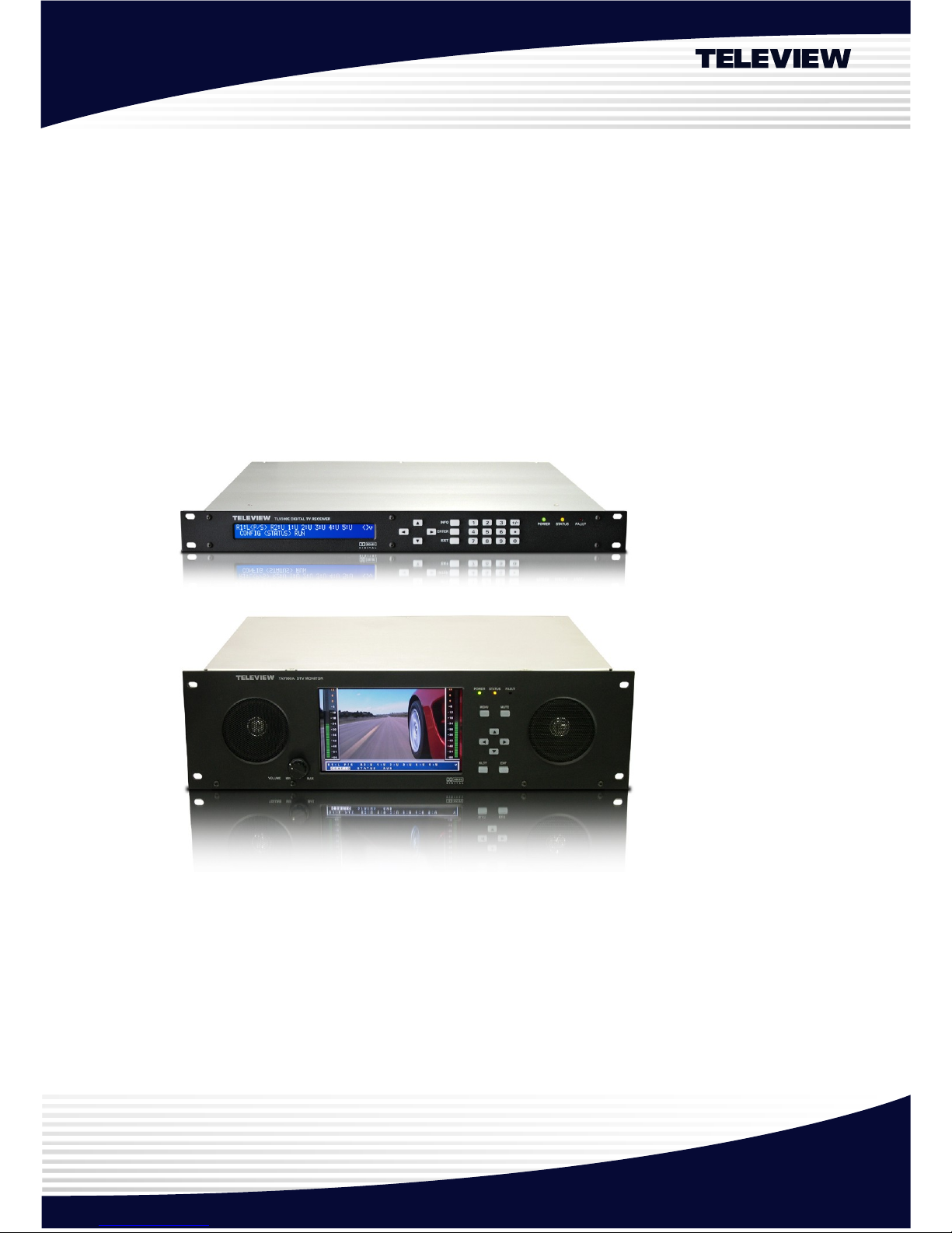
Professional Digital Television Receiver
TLV-300E™, TLV-300E/M™
HDTV Monitor TAV900A
User’s Manual
Version 2.0 (For FW V2.1.9, FPGA V3.1)
May 11, 2010
Teleview
Corporate Headquarter Teleview, Inc. 355-1 Yatap, Bundang, S eongnam, Gy eonggi, 463-828, Republic of K orea
E-mail: sales @teleview.com http:// www.teleview.com

TLV-300E/TAV-900A Professional Digital TV Receiver User’s Manual
Table of Contents
1. OVERVIEW 7
1.1 Introduction 7
1.2 Delivered Contents 8
1.3 Front Panel Overview 8
1.3.1 Alphanumeric Display 10
1.3.2 Function Buttons 11
1.3.3 Numeric Buttons 12
1.4 Rear Panel Overview 13
1.4.1 Overview 13
1.4.2 Video Output 14
1.4.3 Audio Output 15
1.4.4 Digital Output BNC Connectors (AES3/DVB-ASI/SMPTE-310M) 15
1.4.5 DVB-ASI/SMPTE-310M Input BNC Connectors 16
1.4.6 RF Input Connectors 16
1.4.7 Communication Port 16
1.4.8 FAULT Output Port 16
1.4.9 Power Switch & Inlet 16
1.5 BNC Configuration 17
2. GETTING STARTED 18
2.1 Initial Hook-up 18
2.2 Verifying YPbPr or RGB Component Video Output (Only if applicable display is attached) 19
2.3 Verifying SDI Video Output (Only if applicable display is connected) 19
2.4 Verifying Composite Video Output (Only if applicable display is connected) 22
2.5 Verifying 8VSB Digital TV Signal Decoding thru RF Input (Only if you have 8VSB RF input available)
22
2.6 Verifying Digital TV Signal Decoding thru DVB-ASI or SMPTE-310M Input (Only if you have this
source available) 23
2.7 Verifying QAM Digital TV Signal Decoding thru Cable TV Input (Only if you have Digital Cable RF
input available) 24
2.8 Verifying Analog Audio Output 25
2.9 Using DVB-ASI or SMPTE-310M TS Output 25
2.10 Using Digital Audio Output 25
Version 2.0 2

TLV-300E/TAV-900A Professional Digital TV Receiver User’s Manual
2.11 Using FAULT Output 26
2.12 SNMP Network Management 26
2.13 Saving Configuration 26
2.14 Menu Using OSD 26
3. MENU DICTIONARY 28
3.1 Overview 28
3.2 CONFIG Menu 29
3.2.1 CONFIG Menu Overview 29
3.2.2 CONFIG/MAIN sub-menu 30
3.2.3 CONFIG/SUB sub-menu 35
3.2.4 CONFIG/RF-IN1 sub-menu 36
3.2.5 CONFIG/RF-IN2 sub-menu 36
3.2.6 CONFIG/BNC OUT(AES/ASI/SMPTE310M) sub-menu 37
3.2.7 CONFIG/SYSTEM sub-menu 38
3.2.8 CONFIG/NETWORK 39
3.2.9 CONFIG/FAULT OUT sub-menu 40
3.2.10 CONFIG/PRIORITY 41
3.2.11 CONFIG/AUTO SELECTION DELAY: 42
3.2.12 CONFIG/SI MODE 42
3.3 STATUS Menu 42
3.3.1 STATUS/MAIN sub-menu 43
3.3.2 STATUS/SUB sub-menu 46
3.3.3 STATUS/RF-IN1 and STATUS/RF-IN2 sub-menu 47
3.3.4 STATUS/INPUT sub-menu 47
3.3.5 STATUS/VERSION sub-menu 48
3.3.6 STATUS/SERIAL NUMBER sub-menu 48
3.3.7 STATUS/MAC-ADDRESS sub-menu 48
3.3.8 STATUS/LICENSE LEVEL sub-menu 48
3.4 SAVE PROFILE Menu 49
3.5 RECALL PROFILE Menu 49
3.6 AUTO SEARCH Menu 49
3.7 DEFAULT Menu 49
3.8 DIAGNOSIS Menu 52
4. HOW TO UPGRADE FIRMWARE 54
Version 2.0 3

TLV-300E/TAV-900A Professional Digital TV Receiver User’s Manual
4.1 Firmware Upgrade from Teleview Web Site(TELEVIEW URL) 54
4.2 Firmware Upgrade with FTP(TLVFTPD) 54
4.3 Firmware Upgrade with USB Port(USB) 55
5. HELP 56
5.1 Trouble Shooting 56
6. SYSTEM STATUS LOG 57
7. SPECIFICATIONS1 58
8. INPUT AND OUTPUT SIGNAL SPECIFICATIONS2 60
8.1 Audio Output 60
8.2 Main Video Output – Component 61
8.3 Main Video Output – SDI 61
8.4 Sub Video Output –Composite 62
8.5 USB 62
8.6 Ethernet 62
8.7 SMPTE-310M Input 63
8.8 SMPTE-310M Output 63
8.9 DVB-ASI Input 63
8.10 DVB-ASI Output 64
8.11 RF Input 64
8.12 FAULT Output 64
8.13 Power Inlet 65
9. FACTORY OPTION 66
9.1 TLV-300E/M option 66
9.2 DVB-T reception option 66
REFERENCES 67
Version 2.0 4

TLV-300E/TAV-900A Professional Digital TV Receiver User’s Manual
IMPORTANT SAFETY INSTRUCTIONS:
Important safety instructions shall be provided with each apparatus. These instructions shall be in a
separate booklet or sheet, or be located before any operating instructions in an instruction for
installation or use and supplied with the apparatus. This information shall be given in a language
acceptable to the country where the apparatus is intended to be used.
The important safety instructions shall be entitled “IMPORTANT SAFETY INSTRUCTIONS”. The
following safety instructions shall be include where applicable, and, when used, shall be verbatim
as follows. Additional safety information is not prohibited from being included by adding statements
after the end of the following safety instruction list. At the manufacturer’s option, a picture or
drawing that illustrates the intent of a specific safety instruction is not prohibited from being placed
immediately adjacent to that safety instruction.
Read these instructions.
Keep these instructions.
Heed all warnings.
Follow all instructions.
Do not use this apparatus near water.
Clean only with a dry cloth.
Do not block any of the ventilation openings. Install in accordance with the manufacturer’s instructions.
Do not install near any heat sources such as radiators, heat registers, stoves, or other apparatus (including
amplifiers) that produce heat.
Do not defeat the safety purpose of the polarized or grounding type plug. A polarized plug has two blades
with one wider than the other. A grounding type plug has two blades and a third grounding prong. The wide
blade or the third prong is provided for your safety. When the provided plug does not fit into your outlet,
consult an electrician for replacement of the obsolete outlet.
Protect the power cord from being walked on or pinched particularly at plugs, convenience receptacles, and
the point where they exit from the apparatus.
Only use the attachments/accessories specified by the manufacturer.
Unplug this apparatus during lightning storms or when unused for long periods of time.
Refer all servicing to qualified service personnel. Servicing is required when the apparatus has been
damaged in any way, such as power supply cord or plug is damaged, liquid has been spilled or objects have
fallen into the apparatus, the apparatus has been exposed to rain or moisture, does not operate normally, or
has been dropped.
The apparatus should not be exposed to water (dripping or splashing) and no objects filled with liquids, such
as vases, should be placed on the apparatus.
This equipment shall be connected to mains socket outlet with a protective earth connection.
Version 2.0 5
TLV-300E/TAV-900A Professional Digital TV Receiver User’s Manual
CAUTION : TO REDUCE THE RISK OF
ELECTRIC SHOCK, DO NOT
REMOVE COVER (OR BACK).
NO USER-SERVICEABLE PARTS
INS IDE. REFER SERVICING TO
QUALIF IED SERVICE PERSONNEL.
This symbol is intended to alert the user to the
presence of uninsulated "dang erous voltage" within
the product's enclosure that may be of sufficient
magnitude to constitute a risk of electric shock to
persons.
This symbol is intended to alert the user to the
presence of important operating a nd maintenance
(servicing) instructions in the literatur e
accompanying the appliance.
License Notice:
“Dolby Pro Logic ΙΙ”, and the double-D Symbol are trademarks of Dolby Laboratories. Companies planning to use this
implementation in products must obtain a license from Dolby Laboratories Licensing Corporation before designing such
products.
Version 2.0 6

TLV-300E/TAV-900A Professional Digital TV Receiver User’s Manual
1. OVERVIEW
1.1 INTRODUCTION
The Professional Digital Television Receiver TLV-300E/TAV-900A receives digital broadcasting
signal through various sources and supplies demodulated / decoded video and audio in various
industrial forms of signal.
Designed to be compliant with versatile industrial standard such as MPEG-II MP@ML/HL
[1][2]
, ATSC
[3]
(Advanced Television Systems Committee) and DVB (Digital Video Broadcasting), the TLV-
300E/TAV-900A offers easy connection to various digital televisions and receivers.
The TLV-300E/TAV-900A comes with 8VSB (Vestigial Side Band) and 6MHz 64QAM/256QAM
(Quadrature Amplitude Modulation) reception module for America/Korea terrestrial/cable digital
broadcasting.
The digital broadcasting signal is supported in the forms of DVB-ASI
[4]
, SMPTE-310M
[5]
, or it can
be a radio frequency (RF). The video output is supplied through composite video signal, Y/Pb/Pr
analog video signal with embedded sync and RGBHV analog video signal. In addition, it supports
the SDI (Serial Digital Interface) digital video (SMPTE-292M
[6]
and SMPTE-259M
[7]
) with embedded
audio (PCM audio) for standard definition and high definition. The audio output can be analog
stereo output and digital AES3-id (Audio Engineering Society Standard 3) output.
The receiver has two sets of video / audio decoder, MAIN channel and SUB channel, working
independently. MAIN channel video output is supplied through YpbPr/RGBHV/SDI OUT BNC
connectors and SUB channel video output is supplied through CVBS (composite video baseband
signal) BNC connector. CVBS output works at only 720x480 (576) interlaced mode. The MAIN and
SUB audio output is supplied through L1, R1 and L2, R2 analog audio and AES3-id digital audio for
both channel as well as embedded audio in SDI output.
By supporting SNMP (Simple Network Management), the user can remotely monitor and control
the unit via Ethernet connection. The firmware could be updated easily to recent version via a USB
port and Ethernet. With its slim form factor 1U Rack mountable frame and easy maintenance
method the TLV-300E/TAV-900A can be easily installed and operated.
Version 2.0 7

TLV-300E/TAV-900A Professional Digital TV Receiver User’s Manual
1.2 DELIVERED CONTENTS
When you receive the TLV-300E/TAV-900A from a distributor, the package comes with following
contents:
Table 1 Content in the carton box
Description Quantity
TLV-300E 1RU frame or
TAV-900A 3RU frame
1
AC power cord 1 North America type (Type B) plug and an IEC C13 line socket
or
1 Power cord featuring a
CEE 7/4
plug (Type F, Schuko) and an
IEC C13 line socket.
Audio Cable Converter 1 D-sub 9p to XLR cable
User’s manual 1
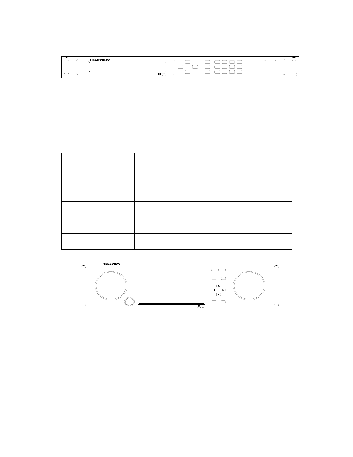
1.3 FRONT PANEL OVERVIEW
The Front panel of TLV-300E can be divided into 4 main parts:
Table 2 Content in the carton box
1 2 lines by 40 characters alphanumeric character display
2 Function buttons (Arrow, LOCK, ENTER, EXIT)
3 Numeric buttons
4 3 LEDs (POWER, STATUS, FAULT)
Version 2.0 8
TLV-300E/TAV-900A Professional Digital TV Receiver User’s Manual
TLV300 E DIGITAL T V RECEIVER
ENTER
EXIT
POWER STATUS FAULT
LOCK
Figure 1 Front Panel View of the TLV-300E Receiver
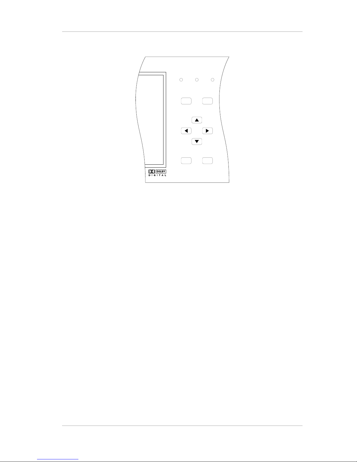
The Front panel of TLV-900A can be divided into 6 main parts:
Table 3 Front panel components
1 7 inch color TFT-LCD display
2 Two speakers
3 Volume knob
4 Function buttons (Menu, Mute, SLCT(==ENTER), EXIT)
5 Arrow buttons
6 3 LEDs (POWER, STATUS, FAULT)
TAV90 0A DT V MONI TOR
POWER
MENU MUTE
STATUS FAULT
SLCT
EXIT
VOLUME MIN MAX
Figure 2 Front Panel View of the TAV-900A Receiver
Version 2.0 9
TLV-300E/TAV-900A Professional Digital TV Receiver User’s Manual
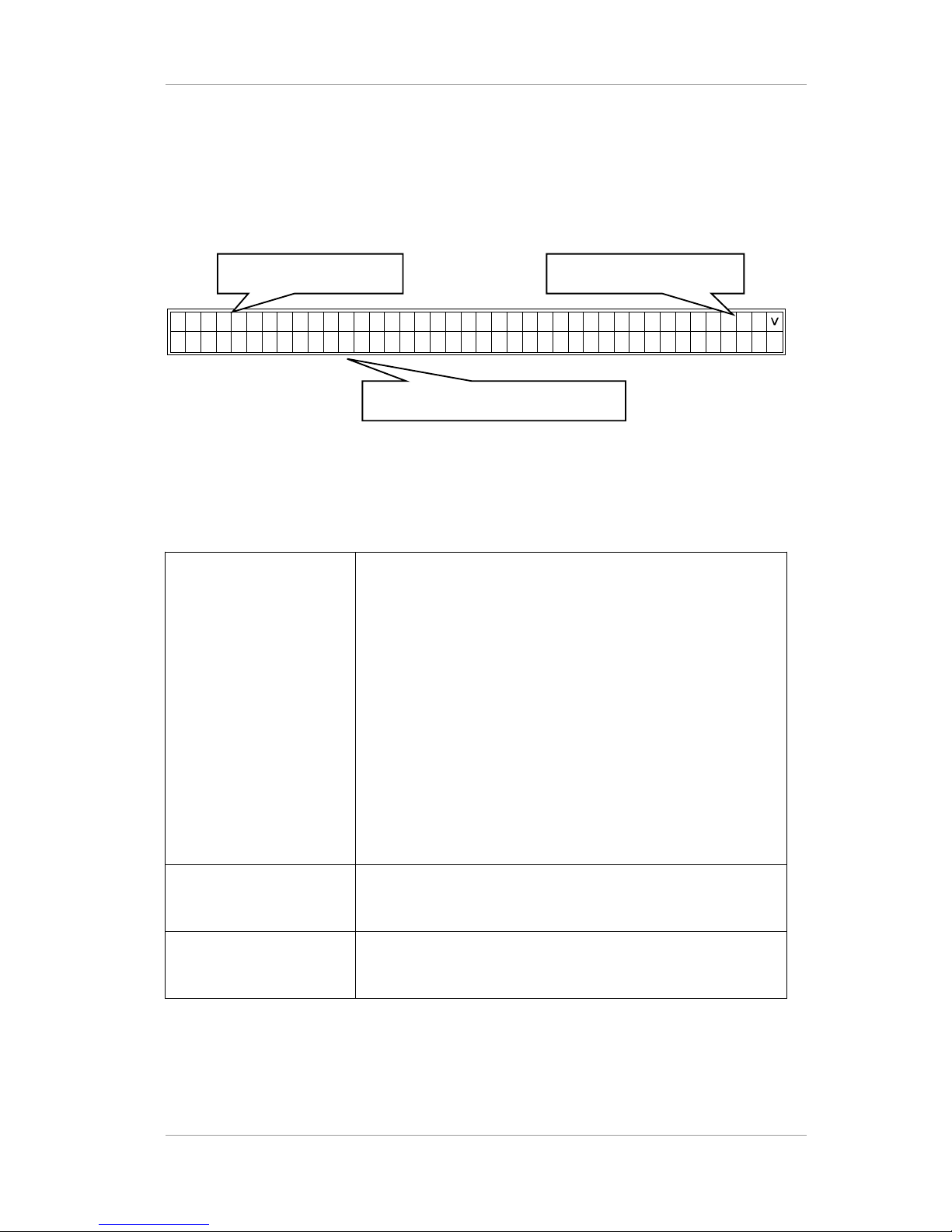
1.3.1 Alphanumeric Display
The status display provides clear viewing of status and menu configuration with 2 lines by 40
characters. It is used to control the TLV-300E directly from the front panel.
.3 2 . 9IF
-
N 1-
B
d
: 4 B-
B 0BxB10C 8L
- :
O 8K -10:
-B3:2:
BR V
- : 5
0S
>
< >R :L 2 -R 1 :
Figure 3 Alphanumeric Display
Table 4 Regions in the alphanumeric display
1. Lock State
In this upper line of the display, R1:L shows that RF input-1 is in
LOCK state, and R2:- means RF input-2 is in UNLOCK state.
B1:-, B2:-, B3:-, B4:-, and B5:- means BNC input-1~5 is in
UNLOCK state.
In the bottom line of the display, RF-IN1:LOCK 8VSB 32.9dB
0.00x10⁻⁸ shows that lock state, modulation system, SNR and
BER value of RF input-1.
User can view the status information of RF-IN2, BNC1~5 by
scolling left/right using <,> arrow buttons.
User can change the INPUT STATUS format into MAIN STATUS
or SUB STATUS using the ^ arrow button.
In the MAIN STATUS, the upper line of the display-MAIN:RF-IN1
shows that MAIN channel is taking input signal from RF-IN1
2. Applicable Button It displays available function buttons for current menu
[ex: ENTER/SLCT (select button); <, >, ^, v (arrow button)]
3. Menu Entries / Status
Bar
It displays sub menus, parameter, or status
Version 2.0 10
1. Lock State 2. Applicable Button
Buttons
3. Menu Entries/ Status Bar
TLV-300E/TAV-900A Professional Digital TV Receiver User’s Manual
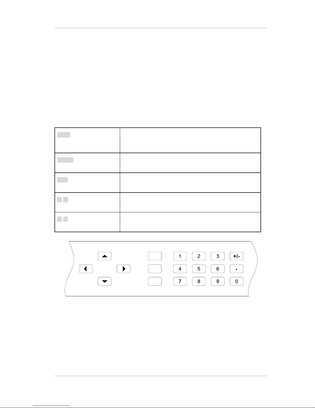
1.3.2 Function Buttons
Front panel has buttons for easy control, which enable complete and simple control of the receiver.
The entire operation of the receiver can be carried out directly using the front panel buttons with the
alphanumeric display. Therefore, the user can easily control and change the settings. The four
direction buttons scroll through the different options within the menus or submenus. The
ENTER/SLCT and EXIT buttons are used to select through the menu options.
Table 5 Buttons in the front panel
LOCK Used to lock front buttons. If once pushed, users can not push
the front buttons. And If pushed again, the lock status of front
buttons is canceled.
ENTER Used to make selections in the menu system and go to the
sub-menu.
EXIT Used to exit the current menu level and return to the previous
one.
◄ ► Allow you to scroll through the different options within sub-
menus, or to move the cursor.
▲ ▼ Allow you to go to next/previous sub-menu within the menu, or
to change the parameter.
LOCK
ENTER
EXIT
Figure 4 Function Buttons and Numeric Buttons of TLV-300E
Version 2.0 11
TLV-300E/TAV-900A Professional Digital TV Receiver User’s Manual
POWER
MENU MUTE
STATUS FAULT
SLCT EXIT
Figure 5 Function Buttons and Numeric Buttons of TAV-900A
1.3.3 Numeric Buttons
Numeric buttons allow you to enter the numbers instead of using the arrow buttons. For example,
instead of using the direction buttons to find program number ‘63’, the user enters the number ‘63’
with the numeric buttons and press ENTER to enter the program number directly. And the buttons
are used to set the channel frequency, channel numbers and etc.
Version 2.0 12
TLV-300E/TAV-900A Professional Digital TV Receiver User’s Manual
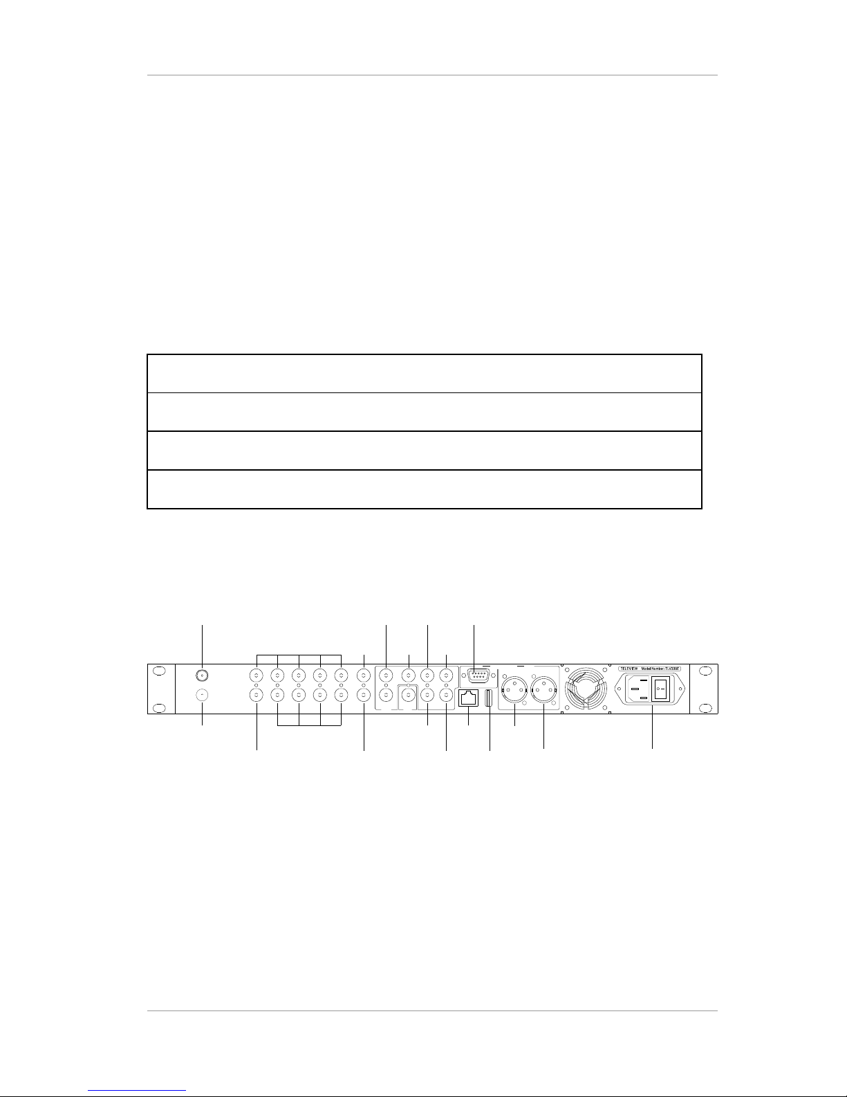
1.4 REAR PANEL OVERVIEW
1.4.1 Overview
The rear panel has all the necessary connections to receive and send the incoming/outgoing
signal.
The real panel can be divided into 4 main parts:
Table 6 Regions in the rear panel
1. Video/audio output part
2. Transport stream (TS) input/output part
3. Communication part
4. Power part
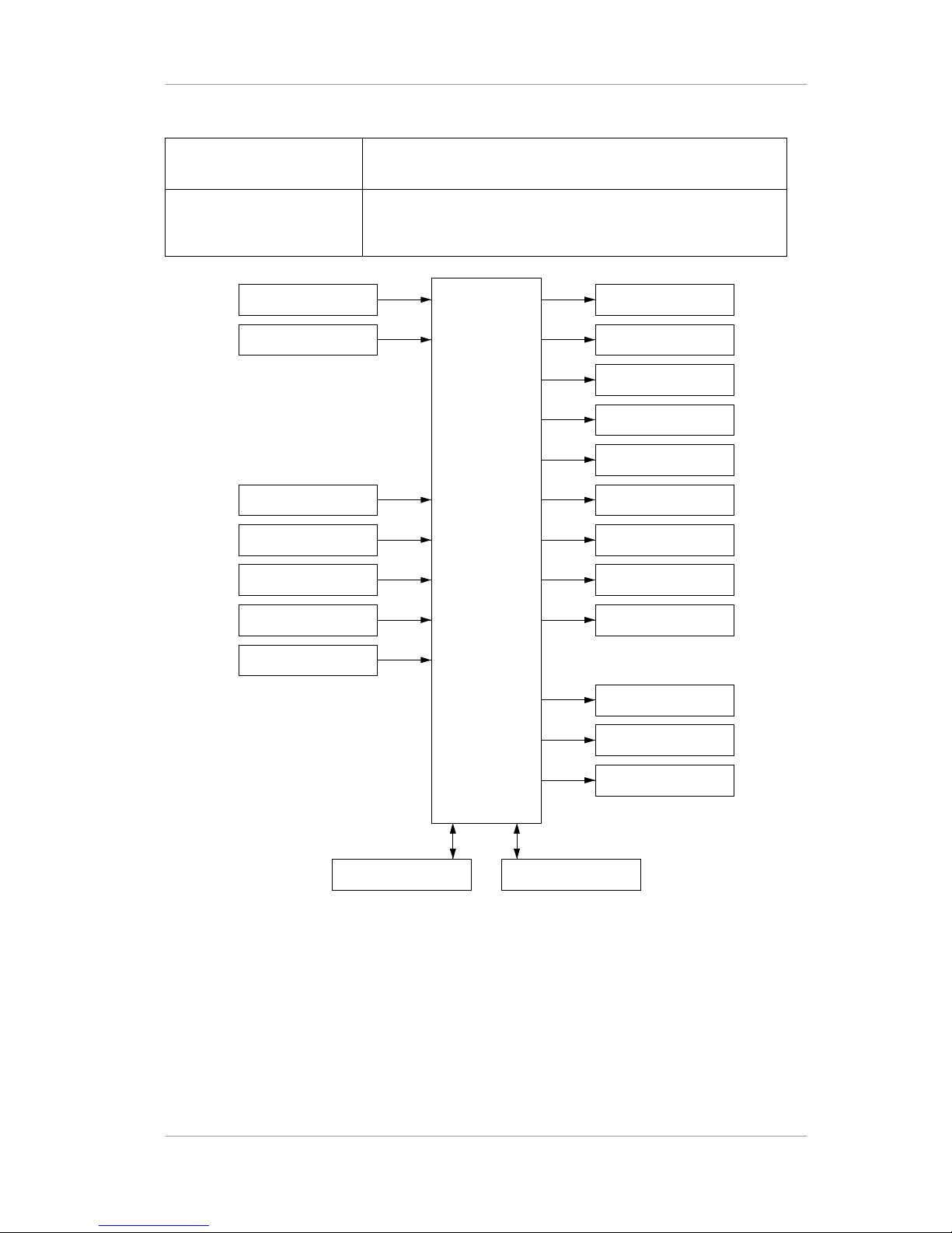
The following diagram and descriptions give you a better understanding of the connections that you
need to make in order to receive and display the incoming signal. For specific information, please
refer to the input/output specifications.
SUB
SUB
MAIN
MAINANALOG AUDIO
ETHERNET
BNC OUT
(AES3/ASI/SMPTE-310M)
BNC IN
(ASI/SMPTE-310M)
RF IN 1
RF IN 2
FAULT
OUT
R1
L1HD OUT
VD OUTNC
Y/G OUT
Pb/B OUT L2/R2
Pr/R OUT
SDI OUT1
USB
NC
1 2 3 4 5
1 2 3 4
100-240V~ 50-60Hz 40W
Figure 6 Rear Panel of the Receiver
Version 2.0 13
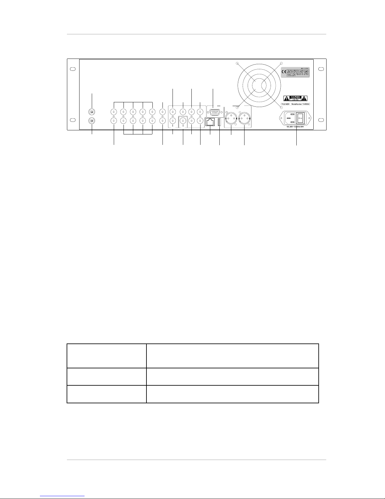
TLV-300E/TAV-900A Professional Digital TV Receiver User’s Manual
SUB
SUB
MAIN
MAINANALOG AUDIO
100-240V~ 50-60Hz 80W
BNC OUT
(AES3/ASI/SMPTE-310M)
BNC IN(ASI/SMPTE-310M)
RF IN 1
RF IN 2
(OPTIONAL)
FAULT
OUT
SDI OUT2
CVBS OUT
HD OUT
VD OUTNC
Y/G OUT
Pb/B OUT
Pr/R OUT
SDI OUT1
NC
1 2 3 4 5
1 2 3 4
ETHERNETR1L1
L2/R2
USB
Figure 7 Rear Panel of the Receiver
Serial number overview: Ex) 88.00.20.03.10.00.00.01
88: Product identification (TLV-300E) / 95: Product identification (TAV-900A)
00: Option
20.03: Year of product produced
10: Month of product produced
00.00.01: Production number
1.4.2 Video Output
In the rear panel, there are analog component video output and one digital video output for MAIN
channel display. Composite output supplied SUB channel video output.
MAIN channel analog video output connectors
YPbPr/RGB Three BNC type connectors enable analog video output signal
(YPbPr output of RGB output)
HD OUT A BNC type connector enables horizontal sync signal.
VD OUT A BNC type connector enables vertical sync signal.
The Y/Pb/Pr signal supports 1080i, 720p, 480p (576p) and 480i (576i) video output mode.
Version 2.0 14

TLV-300E/TAV-900A Professional Digital TV Receiver User’s Manual
MAIN channel digital video output connector
SDI 1 (HD/SD) A BNC type connector enables SDI digital video output signal.
SDI 2 (HD/SD) Identical signal with SDI 1
The SDI signal is valid for 1080i, 720p (30/29.97/25 Hz), and 480i 29.97 Hz/576i 25 Hz video
output mode. Not defined for 480p/576p mode. 480i 30Hz mode is not supported.
SUB channel analog composite video output connector
CVBS OUT A BNC type connector enables analog composite video output
signal.
The composite signal supports 480i (576i) video output mode
1.4.3 Audio Output
In the rear panel, there are one pair of XLR connectors for MAIN channel stereo output and one D-
Sub 9P connector for SUB channel stereo output.
Analog Audio Output Connectors
L1/R1 XLR type connector delivers analog audio output signal for
MAIN channel (CH1/2).
L2/R2 D-Sub 9P type connector delivers analog audio output signal
for SUB channel (CH1/2).
1.4.4 Digital Output BNC Connectors (AES3/DVB-ASI/SMPTE-310M)
There are four output BNCs each can be selected as DVB-ASI out, SMPTE-310M out, MAIN
channel digital audio output or SUB channel digital audio output.
BNC-OUT(AES3/DVBASI/SMPTE-310M-1 ~ 4)
Each BNC type connector can supply DVB-ASI or SMPTE310M or MAIN AES3id digital audio output or SUB AES3id
digital audio output signal.
Version 2.0 15

TLV-300E/TAV-900A Professional Digital TV Receiver User’s Manual
1.4.5 DVB-ASI/SMPTE-310M Input BNC Connectors
There are five input BNCs used to input DVB-ASI or SMPTE-310M format transport stream. The
format is detected automatically.
BNC-IN(DVB-ASI/SMPTE310M-1~5)
BNC type connector enables serial SMPTE-310M and/or DVBASI transport stream input with automatic detection
The TLV-300E/TAV-900A accepts SMPTE-310M and DVB-ASI signal. These transport stream
formats can be transformed to another format (SMPTE-310M output is only available for
19,392,658 Hz bit rate signal source as SMPTE-310M is not compliant with other bit rate stream).
1.4.6 RF Input Connectors
RF Input 1 F type connector allows a radio frequency input.
(8VSB/64QAM/256QAM default, DVB-S2/S or DVB-T option)
RF Input 2 (option) Optional second F type connector allows a radio frequency
input. (8VSB/64QAM/256QAM or DVB-S2/S or DVB-T option)
1.4.7 Communication Port
There are two communication ports, these are:
ETHERNET 10/100M Ethernet port
USB Universal Serial Bus Connector (version 1.1)
An ETHERNET connector is used to monitor and control the receiver.
An USB 1.1 port is used to upgrade a firmware. FAT16 or FAT32 format USB memory is supported.
1.4.8 FAULT Output Port
Relay contact for fault condition indication. The fault condition can be configured from
CONFIG/FAULT OUT menu. FAULT is indicated by Open circuit and No Fault condition is indicated
by closed circuit into Ground.
1.4.9 Power Switch & Inlet
Power on/off switch and power inlet:
Version 2.0 16
TLV-300E/TAV-900A Professional Digital TV Receiver User’s Manual
Power Switch Turn on/off main power
Power Inlet Universal AC-INLET accepts 100–240 VAC and a line frequency
50/60 Hz. IEC C14 type chassis plug
RF IN-1 TLV300E MAIN:PbPr/RGB Out
MAIN: Sync Out
SUB:CVBS Out
MAIN:L1/R1(CH1/2)
AES3/TS OUT, BNC1
AES3/TS OUT, BNC2
AES3/TS OUT, BNC3
AES3/TS OUT, BNC4
MAIN:SDI OUT 1
MAIN:SDI OUT 2
FAULT OUT
USBETHERNET
SUB:L2/R2(CH1/2)
RF IN-2 (option)
TS IN, BNC1
TS IN, BNC2
TS IN, BNC3
TS IN, BNC4
TS IN, BNC5
Figure 8 Conceptual Drawing for Input/Output Connections
1.5 BNC CONFIGURATION
Four set of BNC connector is used for digital audio, SMPTE-310M and DVB-ASI output. Each
connector can be configured to MAIN / SUB digital audio output, SMPTE-310M, or DVB-ASI
output. Digital audio can be compressed audio or decoded PCM signal.
Version 2.0 17

TLV-300E/TAV-900A Professional Digital TV Receiver User’s Manual
2. GETTING STARTED
2.1 INITIAL HOOK-UP
Follow these instructions to connect the TLV-300E/TAV-900A receiver to your video display and
audio amplifier.
Connect the supplied power cable from the AC power inlet on the rear panel to a standard AC outlet. Either
50Hz or 60Hz, 100V-240V is acceptable.
Turn on the switch in the rear panel. The cooling fan will start and the alphanumeric display in the front panel
will show a message with the model name of the receiver while configuration taking place. Allow the
receiver to warm up. (It takes up to 10 seconds.)
Example) display during power on during initial state
< ELT V - 3 00 >
Example) display during power on second booting period
C F GG II NNO RU 1 2
Example) display after booting completed
IF
-
N 1-
B : 4 B- B B1
LU
- :
N KO C:
-B3:2:
R
- : 5
>
< >R :- 2 -R 1 :
In this upper line of the display, R1:- and R2:- shows that RF input -1, 2 are in UNLOCK state.
B1:-, B2:-, B3:-, B4:- and B5:- means BNC-1,2,3,4,5 are UNLOCK state.
In the bottom line of the display, RF-1:UNLOCK means RF input-1 is UNLOCK state.
User can change the RF-IN1 status into RF-IN2,BNC-1,2,3,4,5 status by using <> arrow button.
User can change the INPUT PORT STATUS into MAIN STATUS or SUB STATUS by using ^ arrow button.
The status menu rotates in order by the use of ^ arrow button.
Version 2.0 18
TLV-300E/TAV-900A Professional Digital TV Receiver User’s Manual
2.2 VERIFYING YPBPR OR RGB COMPONENT VIDEO OUTPUT (ONLY IF APPLICABLE DISPLAY IS
ATTACHED)
If you have attached YPbPr display or RGB display, follow this step.
Connect YPbPr type or RGBHV type display into Y/G, Pb/B, Pr/R and HD, VD BNC connector in the rear
panel. The display can be 1920x1080 interlaced resolution or 1280x720 progressive resolution; or enhanced
DTV ready monitor supporting 720x480 (576) progressive or interlaced resolution.
Turn on the unit and use DIAGNOSIS/DEFAULT menu to reset configuration. Then use CONFIG/MAIN/
VIDEO/DISPLY TYPE, CONFIG/MAIN/VIDEO/DISPLAY MODE and CONFIG/MAIN/VIDEO/FRAME
RATE menu to configure video output as your display connected.
Then, turn on the MAIN OSD using CONFIG/MAIN/OSD menu.
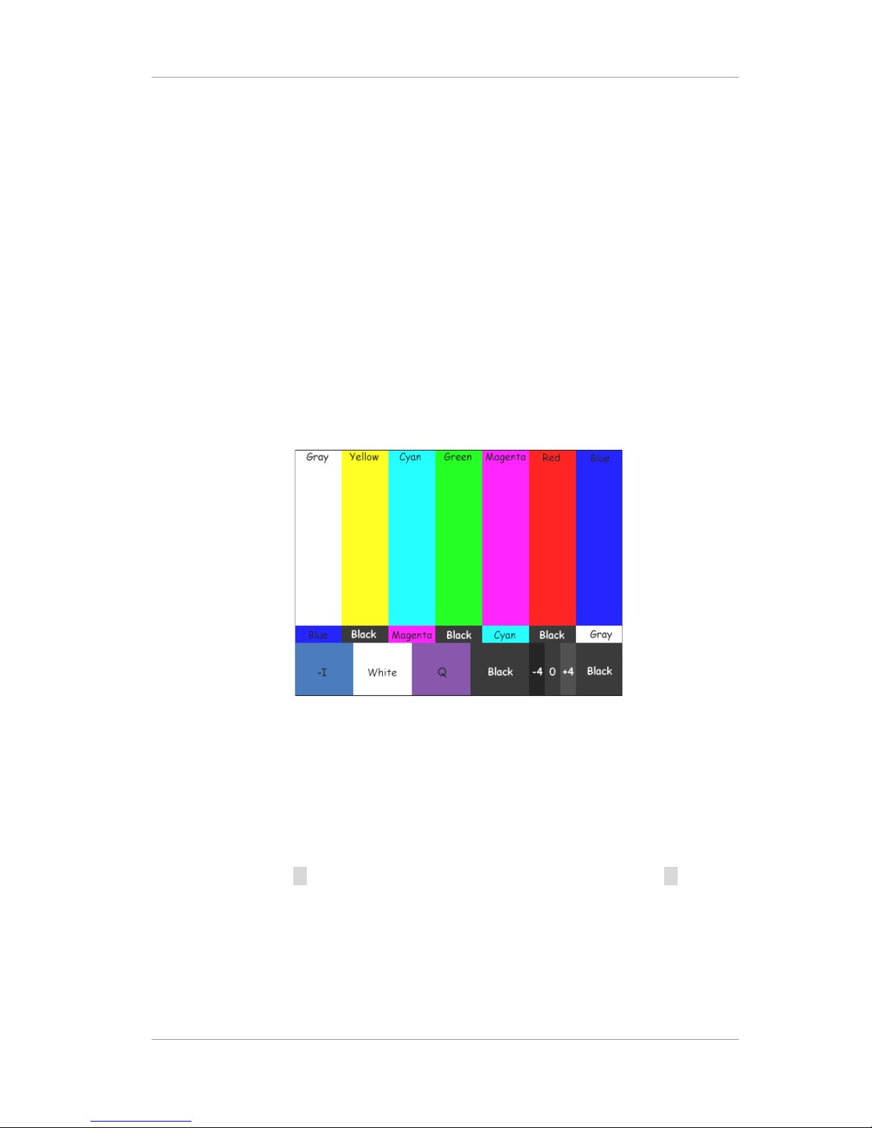
Use DIAGNOSIS/COLORBAR menu ON and OFF to display color bar signal out.
If COLOR BAR is not shown on the display, it means that your video connection has a problem.
Figure 9 Color Bar Pattern with flag
2.3 VERIFYING SDI VIDEO OUTPUT (ONLY IF APPLICABLE DISPLAY IS CONNECTED)
If you have attached SDI display, follow this step.
Attach SDI display into SDI OUTPUT 1 or SDI OUTPUT 2 Connector. SDI 1 and SDI 2 have identical
signal.
Turn on the unit and use button invoke main menu and select DEFAULT menu and press button and
select EXEC and press ENTER button to reset configuration. Then use CONFIG/MAIN/VIDEO/DISPLY
MODE and CONFIG/MAIN/VIDEO/DISPLY TYPE and CONFIG/MAIN/VIDEO/FRAME RATE menu to
configure video output as your display connected.
Then, turn on the MAIN OSD using CONFIG/MAIN/OSD menu.
Use DIAGNOSIS/COLORBAR menu select EXEC to turn ON and OFF to display color bar signal out.
Version 2.0 19
TLV-300E/TAV-900A Professional Digital TV Receiver User’s Manual
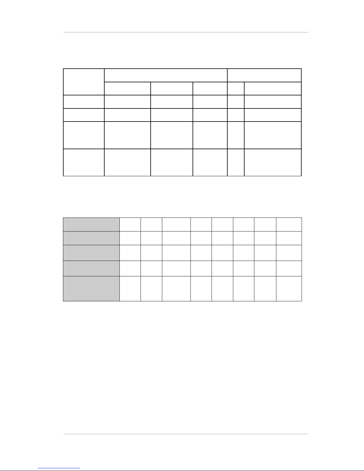
Table 7 Available modes for SDI output
Video
Mode
Frame Rate Embedded Audio
29.97Hz(59.94) 30Hz(60) 25Hz(50) PCM Compressed
1080i O O O O O
720p O O O O O
480p/576p Not defined
(480p)
Not defined
(480p)
Not defined
(576p)
X X
480i/576i O (480i) Not supported
(480i)
O
(576i)
O O
Table 8 SDI Video Specification(FW v2.2.0, FPGA v3.1)
Display mode
1080i 720p 480i 1080i 720p 1080i 720p 576i
Frame rate
30/1.001Hz60/1.001Hz30/1.001
Hz
30Hz 60Hz 25Hz 50Hz 25Hz
Reference HD/SDSDI standard
SMPTE
292M
SMPTE
292M
SMPTE
259M
SMPTE
292M
SMPTE
292M
SMPTE
292M
SMPTE
292M
SMPTE
259M
HD/SD-SDI
parameter
1,2)
Format E Format M Level C Format D Format L Format F - Level C
Video Reference
SMPTE
standard
SMPTE
274Msystem 5
SMPTE
296Msystem 2
SMPTE 125M
or ITU-R
BT.601-5 part
A 525 line
system
SMPTE
274Msystem 4
SMPTE
296Msystem 1
SMPTE
274Msystem 6
SMPTE
296Msystem 3
3)
ITU-R
BT.601-5
part A 625
line system
Note 1) format D,E,F,L,M is supported from SMPTE 292M-1998 Table 1.
Note 2) Level-C, 270 Mb/s , 525/625 component mode is supported from SMPTE-259M-1997.
Note 3) Following SMPTE-296M-system 3.2, 720p/50Hz format is not specified by SMPTE-292M-
1998.
Version 2.0 20
TLV-300E/TAV-900A Professional Digital TV Receiver User’s Manual
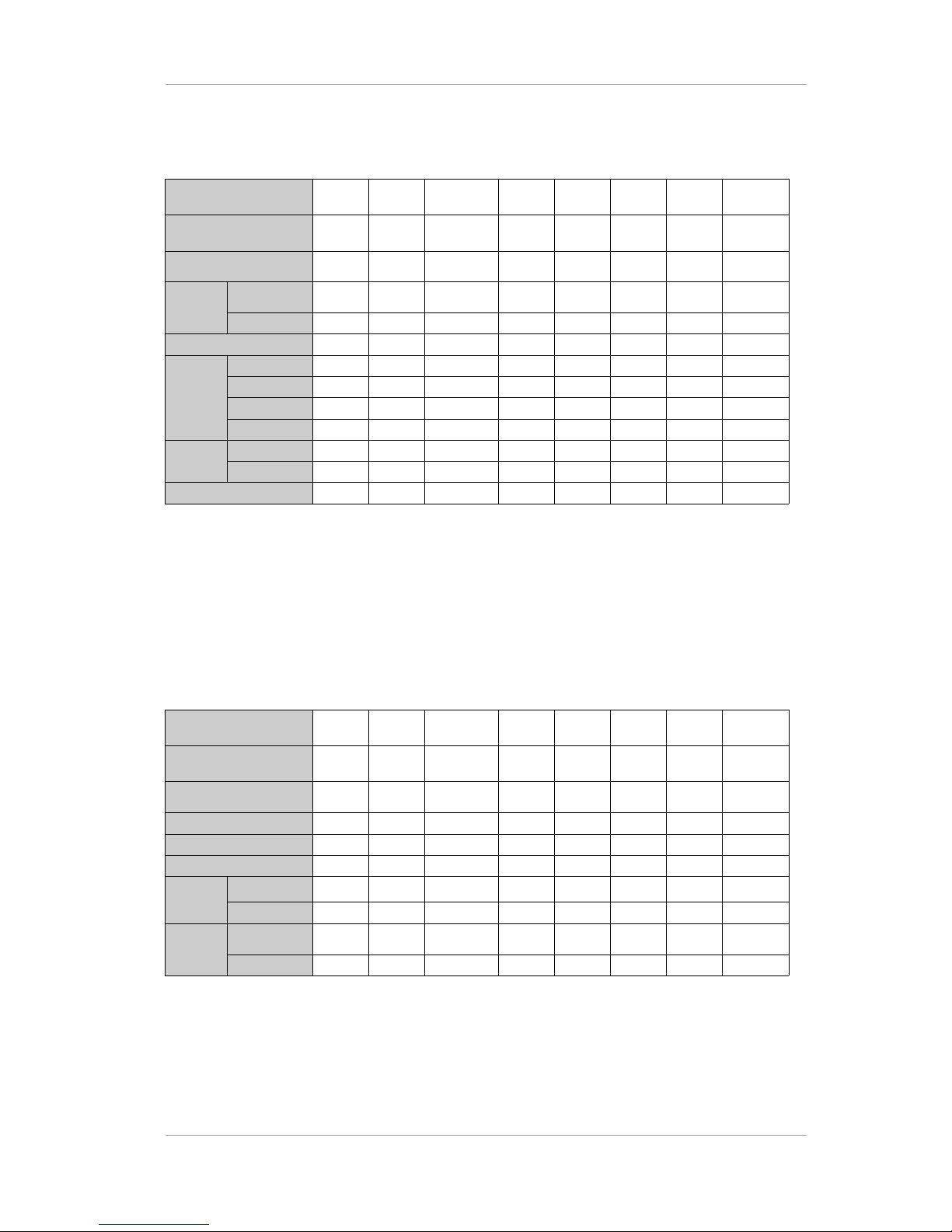
Table 9 Embedded Audio Specification(Since FPGA v3.2)
Display mode 1080i 720p 480i 1080i 720p 1080i 720p 576i
Frame rate
30/1.001Hz60/1.001Hz30/1.001
Hz
30Hz 60Hz 25Hz 50Hz 25Hz
SMPTE standard
SMPTE
299M
SMPTE
299M
SMPTE
272M
SMPTE
299M
SMPTE
299M
SMPTE
299M
SMPTE
299M
SMPTE
272M
Sampling
frequency
Synchronous
3)
48/32/44.1
kHz
48/32/44.1
kHz
48/32/44.1
kHz
48/32/44.1
kHz
48/32/44.1
kHz
48/32/44.1
kHz
48/32/44.1
kHz
48/32/44.1
kHz
Asynchronous
x x x x x x x x
# of Groups
1 1 1 1 1 1 1 1
Channel2)CH1
MAIN-L MAIN-L MAIN-L MAIN-L MAIN-L MAIN-L MAIN-L MAIN-L
CH2
MAIN-R MAIN-R MAIN-R MAIN-R MAIN-R MAIN-R MAIN-R MAIN-R
CH3
SUB-L SUB-L SUB-L SUB-L SUB-L SUB-L SUB-L SUB-L
CH4
SUB-R SUB-R SUB-R SUB-R SUB-R SUB-R SUB-R SUB-R
ACP
location
1)
Line#
9571 9571 12275 9571 9571 9571 9571 10323
Sample#
1928 1288 1444 1928 1288 1928 1288 1444
Compressed audio
Supported Supported Supported Supported Supported Supported Supported Supported
Note 1) ACP : Audio Control Packet
Note 2) MAIN-L: Left audio of MAIN audio decoder, MAIN-R: Right audio of MAIN audio decoder.
Note 3) MAIN-L, MAIN-R embedded audio sampling frequency is synchronized with sampling rate
converter.
Table 10 Embedded Closed Caption Specification(Since FPGA v3.2)
Display mode 1080i 720p 480i 1080i 720p 1080i 720p 576i
Frame rate
30/1.001Hz60/1.001Hz30/1.001
Hz
30Hz 60Hz 25Hz 50Hz 25Hz
SMPTE standard
SMPTE
334M
SMPTE
334M
SMPTE
334M
SMPTE
334M
SMPTE
334M
SMPTE
334M
SMPTE
334M
SMPTE
334M
EIA608 VBI
x x Supported x x x x Supported
EIA608 ANC
Supported Supported Supported Supported Supported Supported Supported Supported
EIA708 ANC
1)
Supported Supported Supported x x x x x
EIA608
ANC
location
Line#
11, 12 11, 12 11, 12 11, 12 11, 12 11, 12 11, 12 11, 12
Sample#
0 0 0 0 0 0 0 0
EIA708
ANC date
location
Line#
13~17,
576~580
13~19 13~18,
276~281
13~17,
576~580
13~19 13~17,
576~580
13~19 13~19,
326~332
Sample#
0 0 0 0 0 0 0 0
Note 1) Service_info_section of CDP is not included.
Version 2.0 21
 Loading...