

Page 1
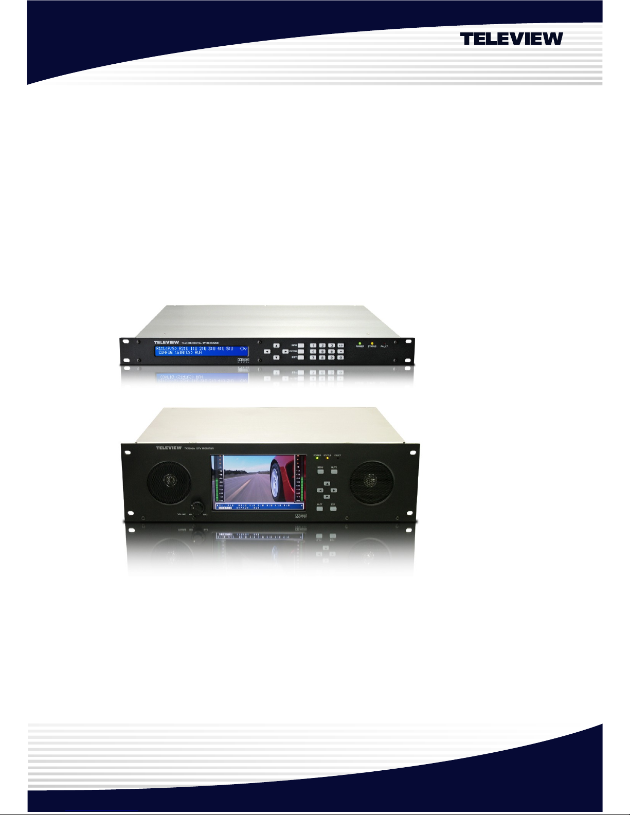
Professional Digital Television Receiver
TLV-300E™, TLV-300E/M™
HDTV Monitor TAV900A
User’s Manual
Version 2.0 (For FW V2.1.9, FPGA V3.1)
May 11, 2010
Teleview
Corporate Headquarter Teleview, Inc. 355-1 Yatap, Bundang, S eongnam, Gy eonggi, 463-828, Republic of K orea
E-mail: sales @teleview.com http:// www.teleview.com
Page 2

TLV-300E/TAV-900A Professional Digital TV Receiver User’s Manual
Table of Contents
1. OVERVIEW 7
1.1 Introduction 7
1.2 Delivered Contents 8
1.3 Front Panel Overview 8
1.3.1 Alphanumeric Display 10
1.3.2 Function Buttons 11
1.3.3 Numeric Buttons 12
1.4 Rear Panel Overview 13
1.4.1 Overview 13
1.4.2 Video Output 14
1.4.3 Audio Output 15
1.4.4 Digital Output BNC Connectors (AES3/DVB-ASI/SMPTE-310M) 15
1.4.5 DVB-ASI/SMPTE-310M Input BNC Connectors 16
1.4.6 RF Input Connectors 16
1.4.7 Communication Port 16
1.4.8 FAULT Output Port 16
1.4.9 Power Switch & Inlet 16
1.5 BNC Configuration 17
2. GETTING STARTED 18
2.1 Initial Hook-up 18
2.2 Verifying YPbPr or RGB Component Video Output (Only if applicable display is attached) 19
2.3 Verifying SDI Video Output (Only if applicable display is connected) 19
2.4 Verifying Composite Video Output (Only if applicable display is connected) 22
2.5 Verifying 8VSB Digital TV Signal Decoding thru RF Input (Only if you have 8VSB RF input available)
22
2.6 Verifying Digital TV Signal Decoding thru DVB-ASI or SMPTE-310M Input (Only if you have this
source available) 23
2.7 Verifying QAM Digital TV Signal Decoding thru Cable TV Input (Only if you have Digital Cable RF
input available) 24
2.8 Verifying Analog Audio Output 25
2.9 Using DVB-ASI or SMPTE-310M TS Output 25
2.10 Using Digital Audio Output 25
Version 2.0 2
Page 3

TLV-300E/TAV-900A Professional Digital TV Receiver User’s Manual
2.11 Using FAULT Output 26
2.12 SNMP Network Management 26
2.13 Saving Configuration 26
2.14 Menu Using OSD 26
3. MENU DICTIONARY 28
3.1 Overview 28
3.2 CONFIG Menu 29
3.2.1 CONFIG Menu Overview 29
3.2.2 CONFIG/MAIN sub-menu 30
3.2.3 CONFIG/SUB sub-menu 35
3.2.4 CONFIG/RF-IN1 sub-menu 36
3.2.5 CONFIG/RF-IN2 sub-menu 36
3.2.6 CONFIG/BNC OUT(AES/ASI/SMPTE310M) sub-menu 37
3.2.7 CONFIG/SYSTEM sub-menu 38
3.2.8 CONFIG/NETWORK 39
3.2.9 CONFIG/FAULT OUT sub-menu 40
3.2.10 CONFIG/PRIORITY 41
3.2.11 CONFIG/AUTO SELECTION DELAY: 42
3.2.12 CONFIG/SI MODE 42
3.3 STATUS Menu 42
3.3.1 STATUS/MAIN sub-menu 43
3.3.2 STATUS/SUB sub-menu 46
3.3.3 STATUS/RF-IN1 and STATUS/RF-IN2 sub-menu 47
3.3.4 STATUS/INPUT sub-menu 47
3.3.5 STATUS/VERSION sub-menu 48
3.3.6 STATUS/SERIAL NUMBER sub-menu 48
3.3.7 STATUS/MAC-ADDRESS sub-menu 48
3.3.8 STATUS/LICENSE LEVEL sub-menu 48
3.4 SAVE PROFILE Menu 49
3.5 RECALL PROFILE Menu 49
3.6 AUTO SEARCH Menu 49
3.7 DEFAULT Menu 49
3.8 DIAGNOSIS Menu 52
4. HOW TO UPGRADE FIRMWARE 54
Version 2.0 3
Page 4

TLV-300E/TAV-900A Professional Digital TV Receiver User’s Manual
4.1 Firmware Upgrade from Teleview Web Site(TELEVIEW URL) 54
4.2 Firmware Upgrade with FTP(TLVFTPD) 54
4.3 Firmware Upgrade with USB Port(USB) 55
5. HELP 56
5.1 Trouble Shooting 56
6. SYSTEM STATUS LOG 57
7. SPECIFICATIONS1 58
8. INPUT AND OUTPUT SIGNAL SPECIFICATIONS2 60
8.1 Audio Output 60
8.2 Main Video Output – Component 61
8.3 Main Video Output – SDI 61
8.4 Sub Video Output –Composite 62
8.5 USB 62
8.6 Ethernet 62
8.7 SMPTE-310M Input 63
8.8 SMPTE-310M Output 63
8.9 DVB-ASI Input 63
8.10 DVB-ASI Output 64
8.11 RF Input 64
8.12 FAULT Output 64
8.13 Power Inlet 65
9. FACTORY OPTION 66
9.1 TLV-300E/M option 66
9.2 DVB-T reception option 66
REFERENCES 67
Version 2.0 4
Page 5

TLV-300E/TAV-900A Professional Digital TV Receiver User’s Manual
IMPORTANT SAFETY INSTRUCTIONS:
Important safety instructions shall be provided with each apparatus. These instructions shall be in a
separate booklet or sheet, or be located before any operating instructions in an instruction for
installation or use and supplied with the apparatus. This information shall be given in a language
acceptable to the country where the apparatus is intended to be used.
The important safety instructions shall be entitled “IMPORTANT SAFETY INSTRUCTIONS”. The
following safety instructions shall be include where applicable, and, when used, shall be verbatim
as follows. Additional safety information is not prohibited from being included by adding statements
after the end of the following safety instruction list. At the manufacturer’s option, a picture or
drawing that illustrates the intent of a specific safety instruction is not prohibited from being placed
immediately adjacent to that safety instruction.
Read these instructions.
Keep these instructions.
Heed all warnings.
Follow all instructions.
Do not use this apparatus near water.
Clean only with a dry cloth.
Do not block any of the ventilation openings. Install in accordance with the manufacturer’s instructions.
Do not install near any heat sources such as radiators, heat registers, stoves, or other apparatus (including
amplifiers) that produce heat.
Do not defeat the safety purpose of the polarized or grounding type plug. A polarized plug has two blades
with one wider than the other. A grounding type plug has two blades and a third grounding prong. The wide
blade or the third prong is provided for your safety. When the provided plug does not fit into your outlet,
consult an electrician for replacement of the obsolete outlet.
Protect the power cord from being walked on or pinched particularly at plugs, convenience receptacles, and
the point where they exit from the apparatus.
Only use the attachments/accessories specified by the manufacturer.
Unplug this apparatus during lightning storms or when unused for long periods of time.
Refer all servicing to qualified service personnel. Servicing is required when the apparatus has been
damaged in any way, such as power supply cord or plug is damaged, liquid has been spilled or objects have
fallen into the apparatus, the apparatus has been exposed to rain or moisture, does not operate normally, or
has been dropped.
The apparatus should not be exposed to water (dripping or splashing) and no objects filled with liquids, such
as vases, should be placed on the apparatus.
This equipment shall be connected to mains socket outlet with a protective earth connection.
Version 2.0 5
Page 6
TLV-300E/TAV-900A Professional Digital TV Receiver User’s Manual
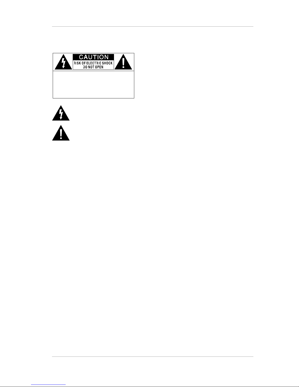
CAUTION : TO REDUCE THE RISK OF
ELECTRIC SHOCK, DO NOT
REMOVE COVER (OR BACK).
NO USER-SERVICEABLE PARTS
INS IDE. REFER SERVICING TO
QUALIF IED SERVICE PERSONNEL.
This symbol is intended to alert the user to the
presence of uninsulated "dang erous voltage" within
the product's enclosure that may be of sufficient
magnitude to constitute a risk of electric shock to
persons.
This symbol is intended to alert the user to the
presence of important operating a nd maintenance
(servicing) instructions in the literatur e
accompanying the appliance.
License Notice:
“Dolby Pro Logic ΙΙ”, and the double-D Symbol are trademarks of Dolby Laboratories. Companies planning to use this
implementation in products must obtain a license from Dolby Laboratories Licensing Corporation before designing such
products.
Version 2.0 6
Page 7

TLV-300E/TAV-900A Professional Digital TV Receiver User’s Manual
1. OVERVIEW
1.1 INTRODUCTION
The Professional Digital Television Receiver TLV-300E/TAV-900A receives digital broadcasting
signal through various sources and supplies demodulated / decoded video and audio in various
industrial forms of signal.
Designed to be compliant with versatile industrial standard such as MPEG-II MP@ML/HL
[1][2]
, ATSC
[3]
(Advanced Television Systems Committee) and DVB (Digital Video Broadcasting), the TLV-
300E/TAV-900A offers easy connection to various digital televisions and receivers.
The TLV-300E/TAV-900A comes with 8VSB (Vestigial Side Band) and 6MHz 64QAM/256QAM
(Quadrature Amplitude Modulation) reception module for America/Korea terrestrial/cable digital
broadcasting.
The digital broadcasting signal is supported in the forms of DVB-ASI
[4]
, SMPTE-310M
[5]
, or it can
be a radio frequency (RF). The video output is supplied through composite video signal, Y/Pb/Pr
analog video signal with embedded sync and RGBHV analog video signal. In addition, it supports
the SDI (Serial Digital Interface) digital video (SMPTE-292M
[6]
and SMPTE-259M
[7]
) with embedded
audio (PCM audio) for standard definition and high definition. The audio output can be analog
stereo output and digital AES3-id (Audio Engineering Society Standard 3) output.
The receiver has two sets of video / audio decoder, MAIN channel and SUB channel, working
independently. MAIN channel video output is supplied through YpbPr/RGBHV/SDI OUT BNC
connectors and SUB channel video output is supplied through CVBS (composite video baseband
signal) BNC connector. CVBS output works at only 720x480 (576) interlaced mode. The MAIN and
SUB audio output is supplied through L1, R1 and L2, R2 analog audio and AES3-id digital audio for
both channel as well as embedded audio in SDI output.
By supporting SNMP (Simple Network Management), the user can remotely monitor and control
the unit via Ethernet connection. The firmware could be updated easily to recent version via a USB
port and Ethernet. With its slim form factor 1U Rack mountable frame and easy maintenance
method the TLV-300E/TAV-900A can be easily installed and operated.
Version 2.0 7
Page 8

TLV-300E/TAV-900A Professional Digital TV Receiver User’s Manual
1.2 DELIVERED CONTENTS
When you receive the TLV-300E/TAV-900A from a distributor, the package comes with following
contents:
Table 1 Content in the carton box
Description Quantity
TLV-300E 1RU frame or
TAV-900A 3RU frame
1
AC power cord 1 North America type (Type B) plug and an IEC C13 line socket
or
1 Power cord featuring a
CEE 7/4
plug (Type F, Schuko) and an
IEC C13 line socket.
Audio Cable Converter 1 D-sub 9p to XLR cable
User’s manual 1
1.3 FRONT PANEL OVERVIEW
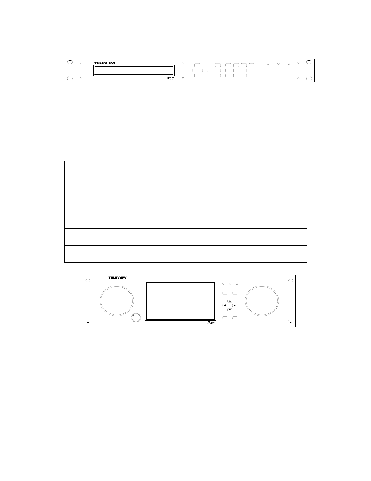
The Front panel of TLV-300E can be divided into 4 main parts:
Table 2 Content in the carton box
1 2 lines by 40 characters alphanumeric character display
2 Function buttons (Arrow, LOCK, ENTER, EXIT)
3 Numeric buttons
4 3 LEDs (POWER, STATUS, FAULT)
Version 2.0 8
Page 9
TLV-300E/TAV-900A Professional Digital TV Receiver User’s Manual
TLV300 E DIGITAL T V RECEIVER
ENTER
EXIT
POWER STATUS FAULT
LOCK
Figure 1 Front Panel View of the TLV-300E Receiver
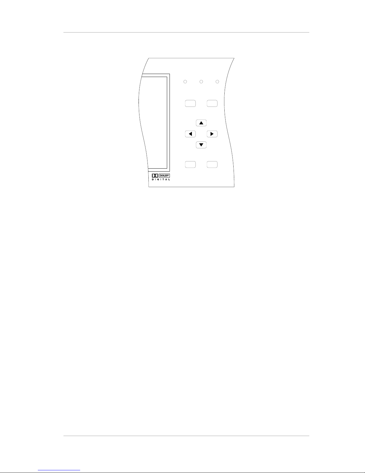
The Front panel of TLV-900A can be divided into 6 main parts:
Table 3 Front panel components
1 7 inch color TFT-LCD display
2 Two speakers
3 Volume knob
4 Function buttons (Menu, Mute, SLCT(==ENTER), EXIT)
5 Arrow buttons
6 3 LEDs (POWER, STATUS, FAULT)
TAV90 0A DT V MONI TOR
POWER
MENU MUTE
STATUS FAULT
SLCT
EXIT
VOLUME MIN MAX
Figure 2 Front Panel View of the TAV-900A Receiver
Version 2.0 9
Page 10
TLV-300E/TAV-900A Professional Digital TV Receiver User’s Manual
1.3.1 Alphanumeric Display
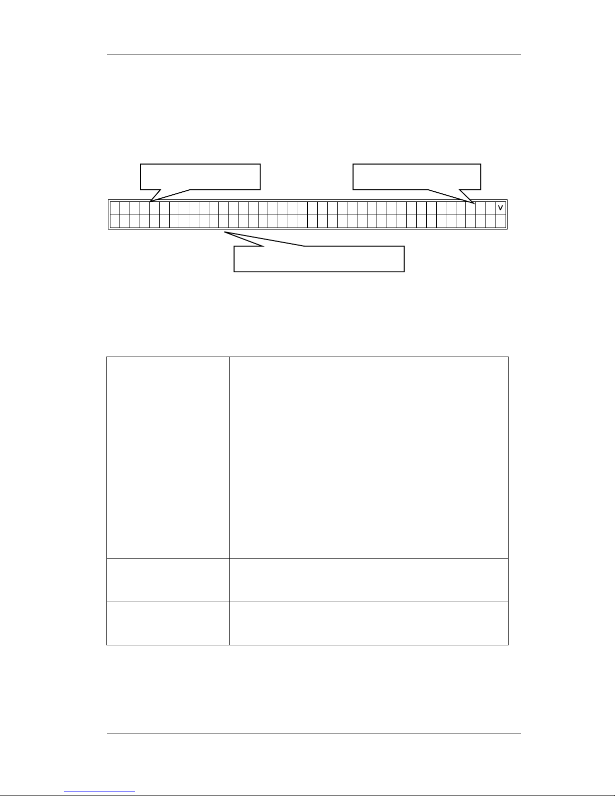
The status display provides clear viewing of status and menu configuration with 2 lines by 40
characters. It is used to control the TLV-300E directly from the front panel.
.3 2 . 9IF
-
N 1-
B
d
: 4 B-
B 0BxB10C 8L
- :
O 8K -10:
-B3:2:
BR V
- : 5
0S
>
< >R :L 2 -R 1 :
Figure 3 Alphanumeric Display
Table 4 Regions in the alphanumeric display
1. Lock State
In this upper line of the display, R1:L shows that RF input-1 is in
LOCK state, and R2:- means RF input-2 is in UNLOCK state.
B1:-, B2:-, B3:-, B4:-, and B5:- means BNC input-1~5 is in
UNLOCK state.
In the bottom line of the display, RF-IN1:LOCK 8VSB 32.9dB
0.00x10⁻⁸ shows that lock state, modulation system, SNR and
BER value of RF input-1.
User can view the status information of RF-IN2, BNC1~5 by
scolling left/right using <,> arrow buttons.
User can change the INPUT STATUS format into MAIN STATUS
or SUB STATUS using the ^ arrow button.
In the MAIN STATUS, the upper line of the display-MAIN:RF-IN1
shows that MAIN channel is taking input signal from RF-IN1
2. Applicable Button It displays available function buttons for current menu
[ex: ENTER/SLCT (select button); <, >, ^, v (arrow button)]
3. Menu Entries / Status
Bar
It displays sub menus, parameter, or status
Version 2.0 10
1. Lock State 2. Applicable Button
Buttons
3. Menu Entries/ Status Bar
Page 11
TLV-300E/TAV-900A Professional Digital TV Receiver User’s Manual
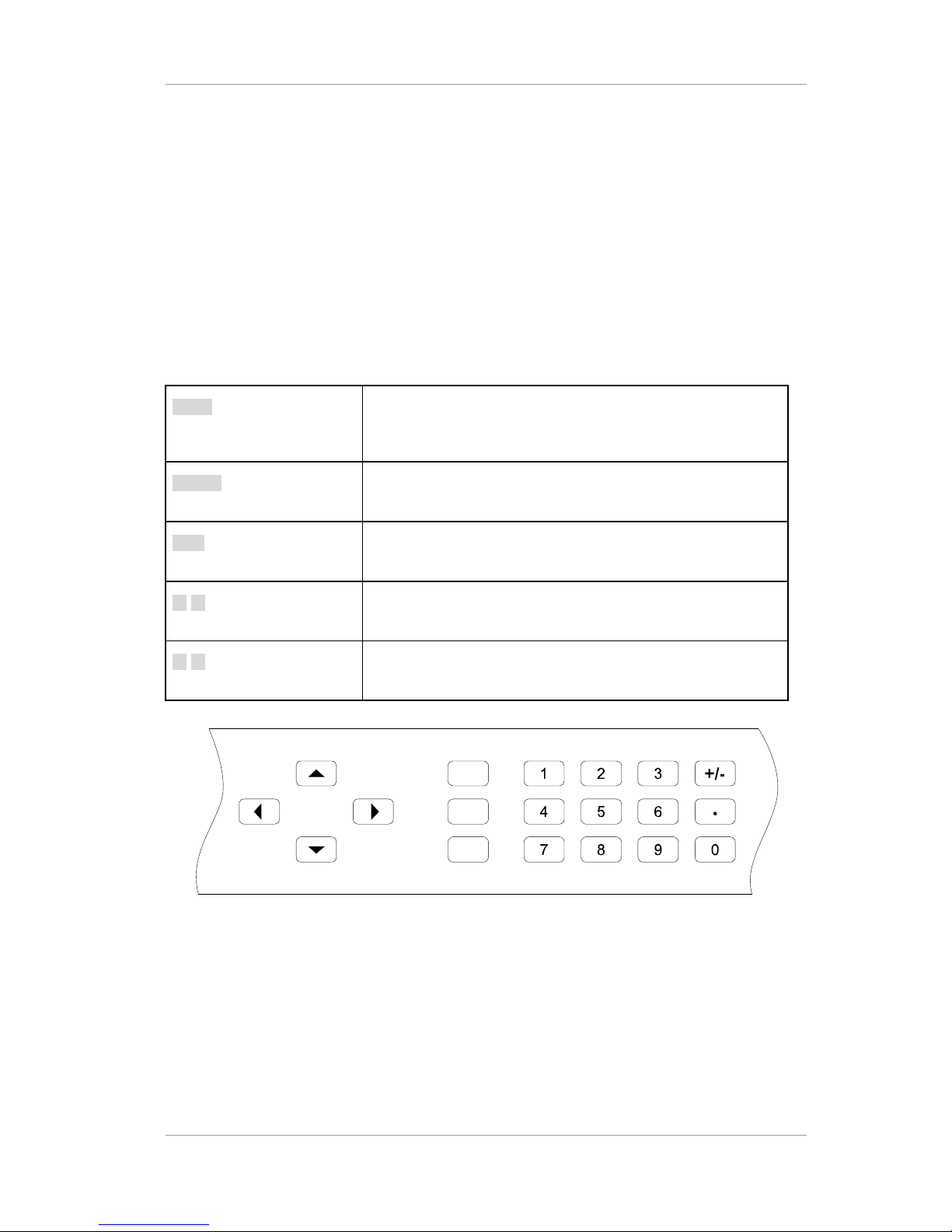
1.3.2 Function Buttons
Front panel has buttons for easy control, which enable complete and simple control of the receiver.
The entire operation of the receiver can be carried out directly using the front panel buttons with the
alphanumeric display. Therefore, the user can easily control and change the settings. The four
direction buttons scroll through the different options within the menus or submenus. The
ENTER/SLCT and EXIT buttons are used to select through the menu options.
Table 5 Buttons in the front panel
LOCK Used to lock front buttons. If once pushed, users can not push
the front buttons. And If pushed again, the lock status of front
buttons is canceled.
ENTER Used to make selections in the menu system and go to the
sub-menu.
EXIT Used to exit the current menu level and return to the previous
one.
◄ ► Allow you to scroll through the different options within sub-
menus, or to move the cursor.
▲ ▼ Allow you to go to next/previous sub-menu within the menu, or
to change the parameter.
LOCK
ENTER
EXIT
Figure 4 Function Buttons and Numeric Buttons of TLV-300E
Version 2.0 11
Page 12
TLV-300E/TAV-900A Professional Digital TV Receiver User’s Manual
POWER
MENU MUTE
STATUS FAULT
SLCT EXIT
Figure 5 Function Buttons and Numeric Buttons of TAV-900A
1.3.3 Numeric Buttons
Numeric buttons allow you to enter the numbers instead of using the arrow buttons. For example,
instead of using the direction buttons to find program number ‘63’, the user enters the number ‘63’
with the numeric buttons and press ENTER to enter the program number directly. And the buttons
are used to set the channel frequency, channel numbers and etc.
Version 2.0 12
Page 13
TLV-300E/TAV-900A Professional Digital TV Receiver User’s Manual
1.4 REAR PANEL OVERVIEW
1.4.1 Overview
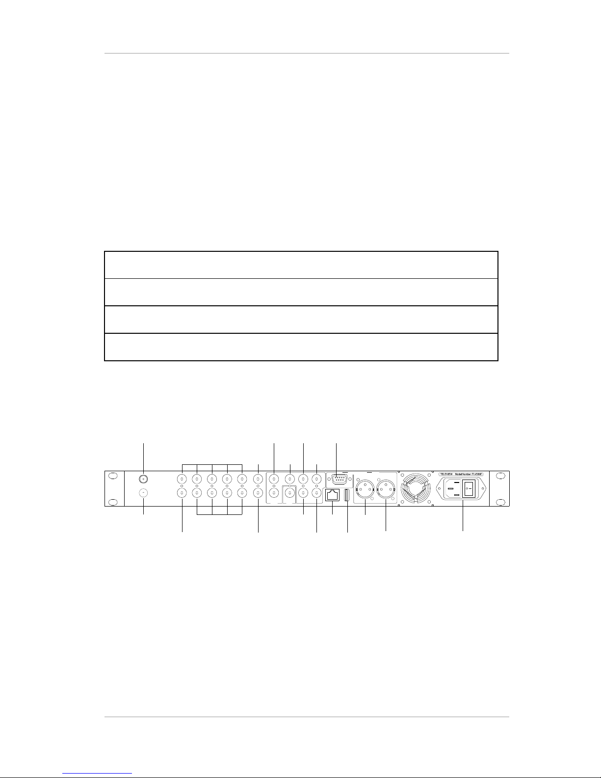
The rear panel has all the necessary connections to receive and send the incoming/outgoing
signal.
The real panel can be divided into 4 main parts:
Table 6 Regions in the rear panel
1. Video/audio output part
2. Transport stream (TS) input/output part
3. Communication part
4. Power part
The following diagram and descriptions give you a better understanding of the connections that you
need to make in order to receive and display the incoming signal. For specific information, please
refer to the input/output specifications.
SUB
SUB
MAIN
MAINANALOG AUDIO
ETHERNET
BNC OUT
(AES3/ASI/SMPTE-310M)
BNC IN
(ASI/SMPTE-310M)
RF IN 1
RF IN 2
FAULT
OUT
R1
L1HD OUT
VD OUTNC
Y/G OUT
Pb/B OUT L2/R2
Pr/R OUT
SDI OUT1
USB
NC
1 2 3 4 5
1 2 3 4
100-240V~ 50-60Hz 40W
Figure 6 Rear Panel of the Receiver
Version 2.0 13
Page 14
TLV-300E/TAV-900A Professional Digital TV Receiver User’s Manual
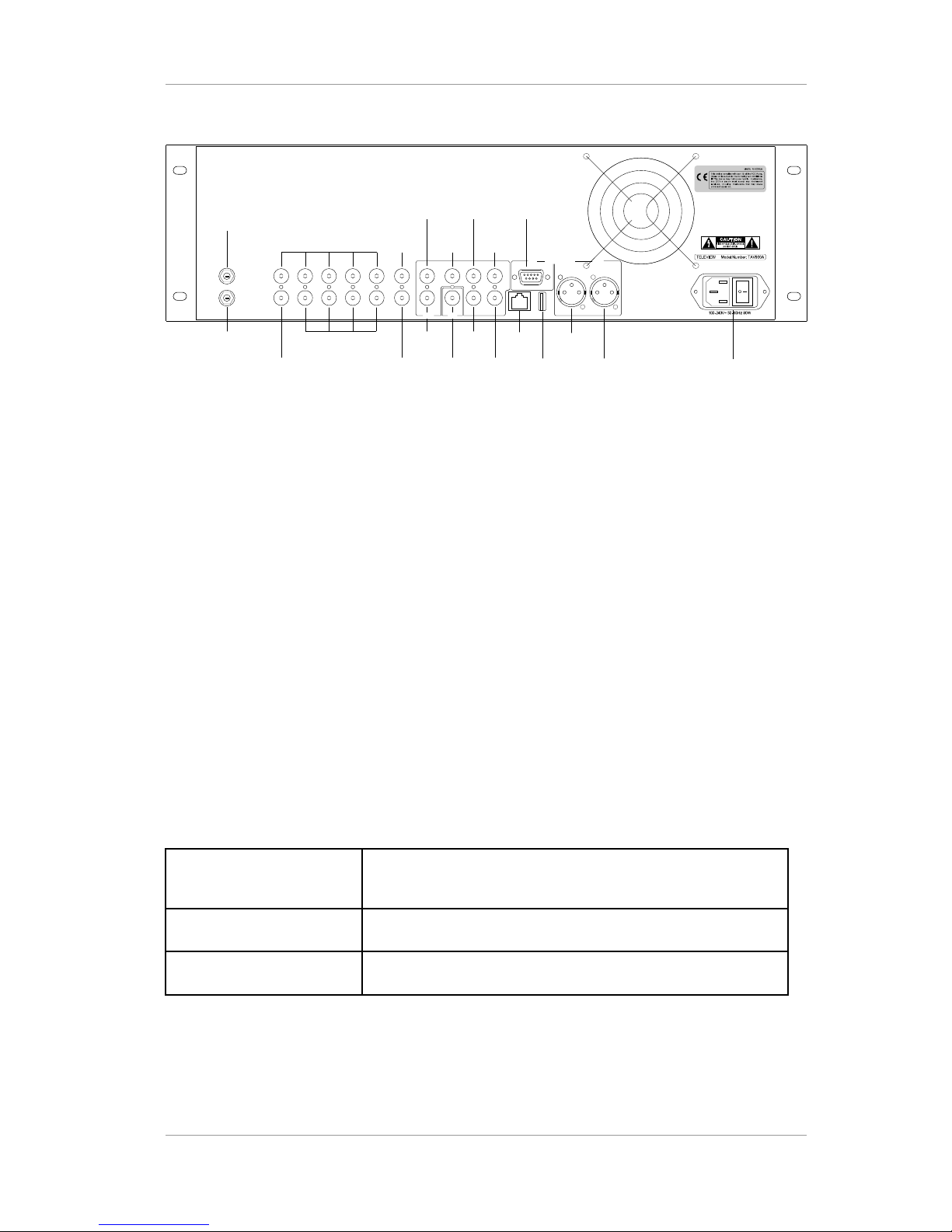
SUB
SUB
MAIN
MAINANALOG AUDIO
100-240V~ 50-60Hz 80W
BNC OUT
(AES3/ASI/SMPTE-310M)
BNC IN(ASI/SMPTE-310M)
RF IN 1
RF IN 2
(OPTIONAL)
FAULT
OUT
SDI OUT2
CVBS OUT
HD OUT
VD OUTNC
Y/G OUT
Pb/B OUT
Pr/R OUT
SDI OUT1
NC
1 2 3 4 5
1 2 3 4
ETHERNETR1L1
L2/R2
USB
Figure 7 Rear Panel of the Receiver
Serial number overview: Ex) 88.00.20.03.10.00.00.01
88: Product identification (TLV-300E) / 95: Product identification (TAV-900A)
00: Option
20.03: Year of product produced
10: Month of product produced
00.00.01: Production number
1.4.2 Video Output
In the rear panel, there are analog component video output and one digital video output for MAIN
channel display. Composite output supplied SUB channel video output.
MAIN channel analog video output connectors
YPbPr/RGB Three BNC type connectors enable analog video output signal
(YPbPr output of RGB output)
HD OUT A BNC type connector enables horizontal sync signal.
VD OUT A BNC type connector enables vertical sync signal.
The Y/Pb/Pr signal supports 1080i, 720p, 480p (576p) and 480i (576i) video output mode.
Version 2.0 14
Page 15

TLV-300E/TAV-900A Professional Digital TV Receiver User’s Manual
MAIN channel digital video output connector
SDI 1 (HD/SD) A BNC type connector enables SDI digital video output signal.
SDI 2 (HD/SD) Identical signal with SDI 1
The SDI signal is valid for 1080i, 720p (30/29.97/25 Hz), and 480i 29.97 Hz/576i 25 Hz video
output mode. Not defined for 480p/576p mode. 480i 30Hz mode is not supported.
SUB channel analog composite video output connector
CVBS OUT A BNC type connector enables analog composite video output
signal.
The composite signal supports 480i (576i) video output mode
1.4.3 Audio Output
In the rear panel, there are one pair of XLR connectors for MAIN channel stereo output and one D-
Sub 9P connector for SUB channel stereo output.
Analog Audio Output Connectors
L1/R1 XLR type connector delivers analog audio output signal for
MAIN channel (CH1/2).
L2/R2 D-Sub 9P type connector delivers analog audio output signal
for SUB channel (CH1/2).
1.4.4 Digital Output BNC Connectors (AES3/DVB-ASI/SMPTE-310M)
There are four output BNCs each can be selected as DVB-ASI out, SMPTE-310M out, MAIN
channel digital audio output or SUB channel digital audio output.
BNC-OUT(AES3/DVBASI/SMPTE-310M-1 ~ 4)
Each BNC type connector can supply DVB-ASI or SMPTE310M or MAIN AES3id digital audio output or SUB AES3id
digital audio output signal.
Version 2.0 15
Page 16

TLV-300E/TAV-900A Professional Digital TV Receiver User’s Manual
1.4.5 DVB-ASI/SMPTE-310M Input BNC Connectors
There are five input BNCs used to input DVB-ASI or SMPTE-310M format transport stream. The
format is detected automatically.
BNC-IN(DVB-ASI/SMPTE310M-1~5)
BNC type connector enables serial SMPTE-310M and/or DVBASI transport stream input with automatic detection
The TLV-300E/TAV-900A accepts SMPTE-310M and DVB-ASI signal. These transport stream
formats can be transformed to another format (SMPTE-310M output is only available for
19,392,658 Hz bit rate signal source as SMPTE-310M is not compliant with other bit rate stream).
1.4.6 RF Input Connectors
RF Input 1 F type connector allows a radio frequency input.
(8VSB/64QAM/256QAM default, DVB-S2/S or DVB-T option)
RF Input 2 (option) Optional second F type connector allows a radio frequency
input. (8VSB/64QAM/256QAM or DVB-S2/S or DVB-T option)
1.4.7 Communication Port
There are two communication ports, these are:
ETHERNET 10/100M Ethernet port
USB Universal Serial Bus Connector (version 1.1)
An ETHERNET connector is used to monitor and control the receiver.
An USB 1.1 port is used to upgrade a firmware. FAT16 or FAT32 format USB memory is supported.
1.4.8 FAULT Output Port
Relay contact for fault condition indication. The fault condition can be configured from
CONFIG/FAULT OUT menu. FAULT is indicated by Open circuit and No Fault condition is indicated
by closed circuit into Ground.
1.4.9 Power Switch & Inlet
Power on/off switch and power inlet:
Version 2.0 16
Page 17
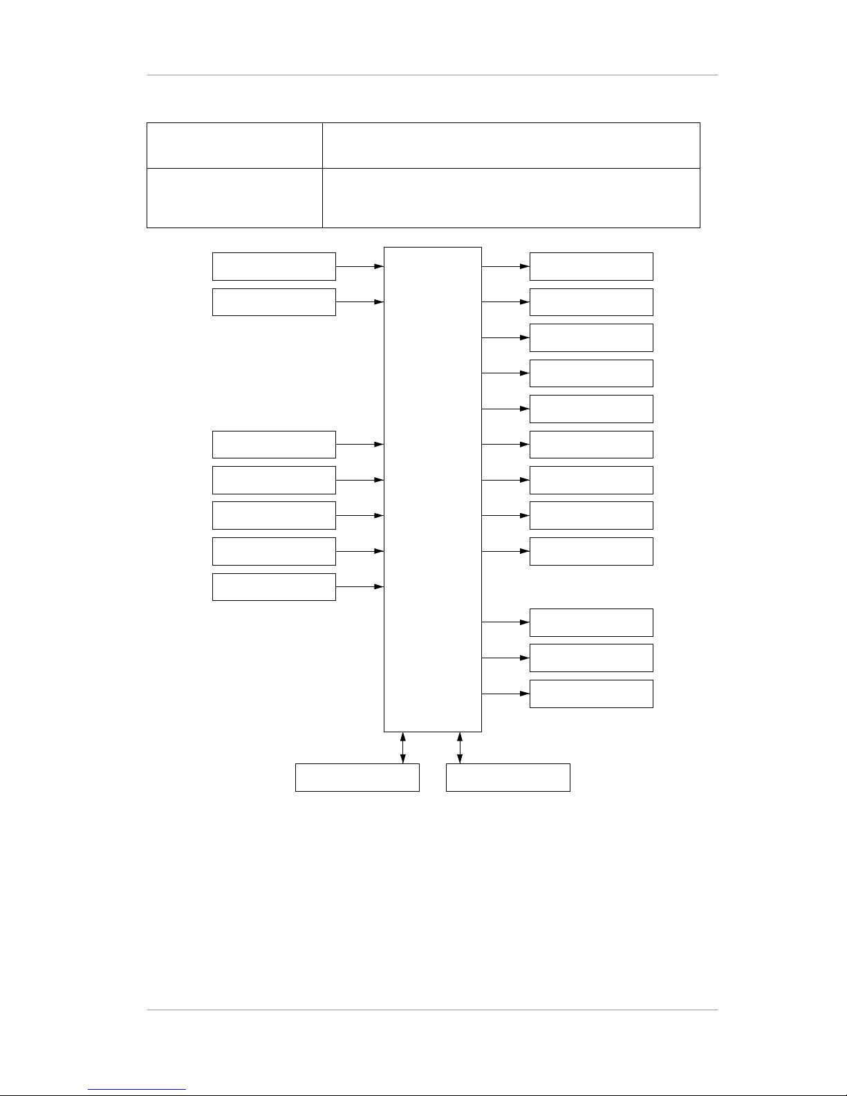
TLV-300E/TAV-900A Professional Digital TV Receiver User’s Manual
Power Switch Turn on/off main power
Power Inlet Universal AC-INLET accepts 100–240 VAC and a line frequency
50/60 Hz. IEC C14 type chassis plug
RF IN-1 TLV300E MAIN:PbPr/RGB Out
MAIN: Sync Out
SUB:CVBS Out
MAIN:L1/R1(CH1/2)
AES3/TS OUT, BNC1
AES3/TS OUT, BNC2
AES3/TS OUT, BNC3
AES3/TS OUT, BNC4
MAIN:SDI OUT 1
MAIN:SDI OUT 2
FAULT OUT
USBETHERNET
SUB:L2/R2(CH1/2)
RF IN-2 (option)
TS IN, BNC1
TS IN, BNC2
TS IN, BNC3
TS IN, BNC4
TS IN, BNC5
Figure 8 Conceptual Drawing for Input/Output Connections
1.5 BNC CONFIGURATION
Four set of BNC connector is used for digital audio, SMPTE-310M and DVB-ASI output. Each
connector can be configured to MAIN / SUB digital audio output, SMPTE-310M, or DVB-ASI
output. Digital audio can be compressed audio or decoded PCM signal.
Version 2.0 17
Page 18

TLV-300E/TAV-900A Professional Digital TV Receiver User’s Manual
2. GETTING STARTED
2.1 INITIAL HOOK-UP
Follow these instructions to connect the TLV-300E/TAV-900A receiver to your video display and
audio amplifier.
Connect the supplied power cable from the AC power inlet on the rear panel to a standard AC outlet. Either
50Hz or 60Hz, 100V-240V is acceptable.
Turn on the switch in the rear panel. The cooling fan will start and the alphanumeric display in the front panel
will show a message with the model name of the receiver while configuration taking place. Allow the
receiver to warm up. (It takes up to 10 seconds.)
Example) display during power on during initial state
< ELT V - 3 00 >
Example) display during power on second booting period
C F GG II NNO RU 1 2
Example) display after booting completed
IF
-
N 1-
B : 4 B- B B1
LU
- :
N KO C:
-B3:2:
R
- : 5
>
< >R :- 2 -R 1 :
In this upper line of the display, R1:- and R2:- shows that RF input -1, 2 are in UNLOCK state.
B1:-, B2:-, B3:-, B4:- and B5:- means BNC-1,2,3,4,5 are UNLOCK state.
In the bottom line of the display, RF-1:UNLOCK means RF input-1 is UNLOCK state.
User can change the RF-IN1 status into RF-IN2,BNC-1,2,3,4,5 status by using <> arrow button.
User can change the INPUT PORT STATUS into MAIN STATUS or SUB STATUS by using ^ arrow button.
The status menu rotates in order by the use of ^ arrow button.
Version 2.0 18
Page 19
TLV-300E/TAV-900A Professional Digital TV Receiver User’s Manual
2.2 VERIFYING YPBPR OR RGB COMPONENT VIDEO OUTPUT (ONLY IF APPLICABLE DISPLAY IS
ATTACHED)
If you have attached YPbPr display or RGB display, follow this step.
Connect YPbPr type or RGBHV type display into Y/G, Pb/B, Pr/R and HD, VD BNC connector in the rear
panel. The display can be 1920x1080 interlaced resolution or 1280x720 progressive resolution; or enhanced
DTV ready monitor supporting 720x480 (576) progressive or interlaced resolution.
Turn on the unit and use DIAGNOSIS/DEFAULT menu to reset configuration. Then use CONFIG/MAIN/
VIDEO/DISPLY TYPE, CONFIG/MAIN/VIDEO/DISPLAY MODE and CONFIG/MAIN/VIDEO/FRAME
RATE menu to configure video output as your display connected.
Then, turn on the MAIN OSD using CONFIG/MAIN/OSD menu.
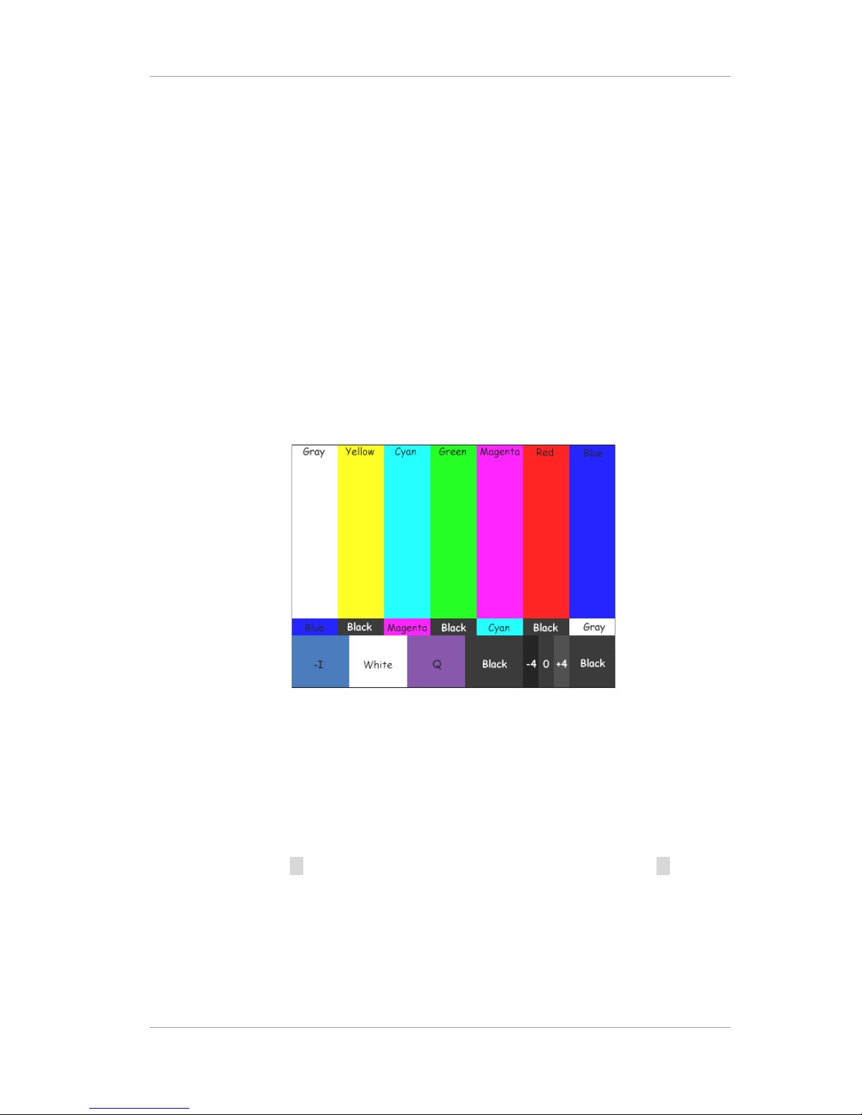
Use DIAGNOSIS/COLORBAR menu ON and OFF to display color bar signal out.
If COLOR BAR is not shown on the display, it means that your video connection has a problem.
Figure 9 Color Bar Pattern with flag
2.3 VERIFYING SDI VIDEO OUTPUT (ONLY IF APPLICABLE DISPLAY IS CONNECTED)
If you have attached SDI display, follow this step.
Attach SDI display into SDI OUTPUT 1 or SDI OUTPUT 2 Connector. SDI 1 and SDI 2 have identical
signal.
Turn on the unit and use button invoke main menu and select DEFAULT menu and press button and
select EXEC and press ENTER button to reset configuration. Then use CONFIG/MAIN/VIDEO/DISPLY
MODE and CONFIG/MAIN/VIDEO/DISPLY TYPE and CONFIG/MAIN/VIDEO/FRAME RATE menu to
configure video output as your display connected.
Then, turn on the MAIN OSD using CONFIG/MAIN/OSD menu.
Use DIAGNOSIS/COLORBAR menu select EXEC to turn ON and OFF to display color bar signal out.
Version 2.0 19
Page 20
TLV-300E/TAV-900A Professional Digital TV Receiver User’s Manual
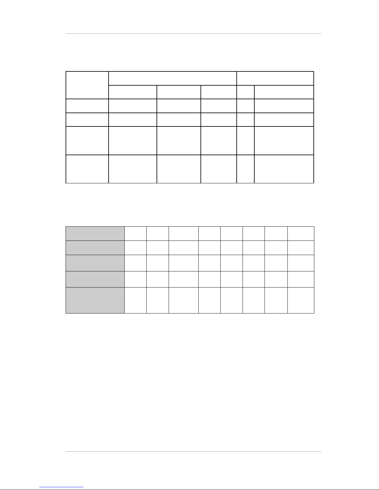
Table 7 Available modes for SDI output
Video
Mode
Frame Rate Embedded Audio
29.97Hz(59.94) 30Hz(60) 25Hz(50) PCM Compressed
1080i O O O O O
720p O O O O O
480p/576p Not defined
(480p)
Not defined
(480p)
Not defined
(576p)
X X
480i/576i O (480i) Not supported
(480i)
O
(576i)
O O
Table 8 SDI Video Specification(FW v2.2.0, FPGA v3.1)
Display mode
1080i 720p 480i 1080i 720p 1080i 720p 576i
Frame rate
30/1.001Hz60/1.001Hz30/1.001
Hz
30Hz 60Hz 25Hz 50Hz 25Hz
Reference HD/SDSDI standard
SMPTE
292M
SMPTE
292M
SMPTE
259M
SMPTE
292M
SMPTE
292M
SMPTE
292M
SMPTE
292M
SMPTE
259M
HD/SD-SDI
parameter
1,2)
Format E Format M Level C Format D Format L Format F - Level C
Video Reference
SMPTE
standard
SMPTE
274Msystem 5
SMPTE
296Msystem 2
SMPTE 125M
or ITU-R
BT.601-5 part
A 525 line
system
SMPTE
274Msystem 4
SMPTE
296Msystem 1
SMPTE
274Msystem 6
SMPTE
296Msystem 3
3)
ITU-R
BT.601-5
part A 625
line system
Note 1) format D,E,F,L,M is supported from SMPTE 292M-1998 Table 1.
Note 2) Level-C, 270 Mb/s , 525/625 component mode is supported from SMPTE-259M-1997.
Note 3) Following SMPTE-296M-system 3.2, 720p/50Hz format is not specified by SMPTE-292M-
1998.
Version 2.0 20
Page 21
TLV-300E/TAV-900A Professional Digital TV Receiver User’s Manual
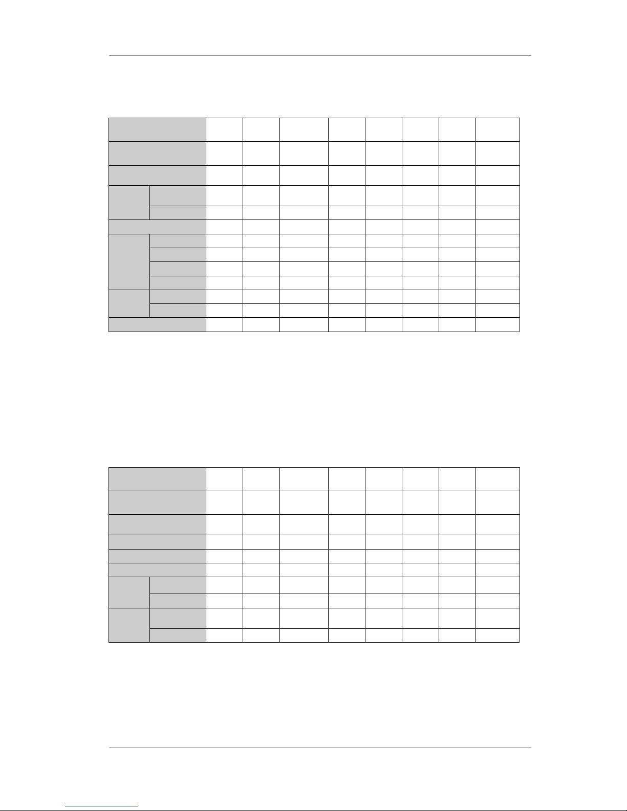
Table 9 Embedded Audio Specification(Since FPGA v3.2)
Display mode 1080i 720p 480i 1080i 720p 1080i 720p 576i
Frame rate
30/1.001Hz60/1.001Hz30/1.001
Hz
30Hz 60Hz 25Hz 50Hz 25Hz
SMPTE standard
SMPTE
299M
SMPTE
299M
SMPTE
272M
SMPTE
299M
SMPTE
299M
SMPTE
299M
SMPTE
299M
SMPTE
272M
Sampling
frequency
Synchronous
3)
48/32/44.1
kHz
48/32/44.1
kHz
48/32/44.1
kHz
48/32/44.1
kHz
48/32/44.1
kHz
48/32/44.1
kHz
48/32/44.1
kHz
48/32/44.1
kHz
Asynchronous
x x x x x x x x
# of Groups
1 1 1 1 1 1 1 1
Channel2)CH1
MAIN-L MAIN-L MAIN-L MAIN-L MAIN-L MAIN-L MAIN-L MAIN-L
CH2
MAIN-R MAIN-R MAIN-R MAIN-R MAIN-R MAIN-R MAIN-R MAIN-R
CH3
SUB-L SUB-L SUB-L SUB-L SUB-L SUB-L SUB-L SUB-L
CH4
SUB-R SUB-R SUB-R SUB-R SUB-R SUB-R SUB-R SUB-R
ACP
location
1)
Line#
9571 9571 12275 9571 9571 9571 9571 10323
Sample#
1928 1288 1444 1928 1288 1928 1288 1444
Compressed audio
Supported Supported Supported Supported Supported Supported Supported Supported
Note 1) ACP : Audio Control Packet
Note 2) MAIN-L: Left audio of MAIN audio decoder, MAIN-R: Right audio of MAIN audio decoder.
Note 3) MAIN-L, MAIN-R embedded audio sampling frequency is synchronized with sampling rate
converter.
Table 10 Embedded Closed Caption Specification(Since FPGA v3.2)
Display mode 1080i 720p 480i 1080i 720p 1080i 720p 576i
Frame rate
30/1.001Hz60/1.001Hz30/1.001
Hz
30Hz 60Hz 25Hz 50Hz 25Hz
SMPTE standard
SMPTE
334M
SMPTE
334M
SMPTE
334M
SMPTE
334M
SMPTE
334M
SMPTE
334M
SMPTE
334M
SMPTE
334M
EIA608 VBI
x x Supported x x x x Supported
EIA608 ANC
Supported Supported Supported Supported Supported Supported Supported Supported
EIA708 ANC
1)
Supported Supported Supported x x x x x
EIA608
ANC
location
Line#
11, 12 11, 12 11, 12 11, 12 11, 12 11, 12 11, 12 11, 12
Sample#
0 0 0 0 0 0 0 0
EIA708
ANC date
location
Line#
13~17,
576~580
13~19 13~18,
276~281
13~17,
576~580
13~19 13~17,
576~580
13~19 13~19,
326~332
Sample#
0 0 0 0 0 0 0 0
Note 1) Service_info_section of CDP is not included.
Version 2.0 21
Page 22

TLV-300E/TAV-900A Professional Digital TV Receiver User’s Manual
2.4 VERIFYING COMPOSITE VIDEO OUTPUT (ONLY IF APPLICABLE DISPLAY IS CONNECTED)
If you have attached composite display supporting NTSC or PAL mode, follow this step.
Connect NTSC (National Television Standards Committee) TV or PAL type TV into CVBS OUT BNC
connector in the rear panel.
Turn on the unit and use DIAGNOSIS/DEFAULT menu to reset configuration. Then use
CONFIG/SUB/VIDEO/FRAME RATE menu to select NTSC mode (29.97 Hz) or PAL (25 Hz) mode
depending the display connected.
Then, turn on the SUB OSD using CONFIG/SUB/OSD menu.
Use DIAGNOSIS/COLORBAR menu ON and OFF to display color bar signal out.
If COLOR BAR is not shown on the display, it means that your video connection has a problem.
2.5 VERIFYING 8VSB DIGITAL TV SIGNAL DECODING THRU RF INPUT (ONLY IF YOU HAVE 8VSB
RF INPUT AVAILABLE)
Connect your TV antenna cable to the unit’s RF Input-1 connector.
Use CONFIG/RF-IN1/FREQUENCY PLAN and choose your RF type. Default is TERRESTRIAL.
If you were watching video other than composite video, enter the channel number with numeric button
following ENTER button in no menu state. The receiver will choose RF-IN1 source for MAIN decoder and
tune to the desired channel. You may also use CONFIG/MAIN/SOURCE to select RF-IN1 and use
CONFIG/MAIN/TUNE CH (tune by channel) as an alternative way. TAV900A does not have numeric
buttons and can not use direct channel selection but need to use menu.
If you were watching video with composite video, use CONFIG/SUB/SOURCE and select RF-IN1 and use
CONFIG/SUB/TUNE CH (tune by channel). The receiver will choose RF-IN1 source for SUB decoder and
tune to the desired channel.
After you tune to the RF signal and exit to the top menu the receiver does not get proper incoming video
signal or setting, then “UNLOCK” message will be shown on the alphanumeric display. If the display shows
some irregular static, video noise, or black screen, make sure your incoming signal quality.
Example) No menu state1 (INPUT PORT STATUS), R1:L indicates LOCK state.
.3 2 . 9IF
-
N 1-
B
d
: 4 B-
B 0BxB10C 8L
- :
O 8K -10:
-B3:2:
BR V
- : 5
0S
>
< >R :L 2 -R 1 :
In this upper line of the display, R1:L shows that RF input-1 is in LOCK state, and R2:- means RF input-2 is
in UNLOCK state. And B1:-, B2:-, B3:-, B4:- and B5:- means BNC-1,2,3,4,5 is in UNLOCK state.
In the bottom line of the display, RF-IN1:LOCK means RF input-1 is in LOCK state.
8VSB means the modulation type of RF input-1 is 8VSB.
32.9dB means SNR of RF input-1 and 0.00x10⁻⁸ means BER of RF input-1.
Example) No menu state2 (MAIN STATUS)
Version 2.0 22
Page 23

TLV-300E/TAV-900A Professional Digital TV Receiver User’s Manual
>
< >
A FIM N R 1I- N:
3S - H DEF MMQR
]
< >94 7 000:
[[
1 /
]
.3 4 . 9 d B 0 x 0 88 -10BV 0S
User can select this menu (MAIN STATUS) by using ^ arrow buttons.
In this upper line of the display, MAIN:RF-IN1 means MAIN channel is taking input signal from RF input-1
port. 8VSB means the modulation type of RF input-1.
In the bottom line of the display, [FREQ:479000] means the channel is tuned to 479,000 kHz (center
frequency of the band).
[MMS-HD] is an example of program name currently tuned.
<1/3> indicates that current channel contains 3 programs and user can select another program using <>
arrow buttons.
User can enter the frequency of RF signal in no menu state2 instead of entering value of the frequency in
CONFIG/RF-IN1/TUNE CENTER FREQ. The frequency unit is in kHz.
If user enters ambiguous number like 57[ENTER], the receiver will prompt user to select from channel 57
and 57MHz.
Example) No menu state3 (Not properly tuned or No input signal)
EF QR
1N C KU N L
94 7 000:
O
[ ]
R -N F IM A I :
:
8 BV S
If it is properly tuned, but there is no video is visible, use the DIAGNOSIS/COLOR BAR menu to check the
cause of the problem. If COLOR BAR is shown on the display, it means that your input signal or setting is
wrong.
2.6 VERIFYING DIGITAL TV SIGNAL DECODING THRU DVB-ASI OR SMPTE-310M INPUT (ONLY
IF YOU HAVE THIS SOURCE AVAILABLE)
Connect TS (transport stream) input (SMPTE-310M or DVB-ASI format) into BNC IN(ASI/SMPTE-310M)1 connector. The SMPTE-310M or DVB-ASI mode is automatically detected and user does not need to
configure input connector to tell the receiver the TS mode.
If you were watching video other than composite video, enter the button ‘1’ with numeric button following
ENTER button. The receiver will choose BNC IN(ASI/SMPTE-310M)-1 source for MAIN decoder and tune
to the stream. You may also use CONFIG/MAIN/SOURCE to select BNC-1 as an alternative way.
If you were watching video with composite video, use CONFIG/SUB/SOURCE and select BNC-1. The
receiver will choose BNC IN(ASI/SMPTE-310M)-1 source for SUB decoder and tune to the stream.
Use left and right arrow button at the no menu state2 to select another program in the channel if current
channel shows multiple program.
Other connector BNC IN(ASI/SMPTE-310M)-2~5 can be used similar way only if user choose number 2~5
instead of 1 above.
As above numeric button method can not distinguish BNC-2 selection and RF channel 2 selections, the
Version 2.0 23
Page 24

TLV-300E/TAV-900A Professional Digital TV Receiver User’s Manual
receiver will prompt user to choose one.
Example) No menu state1 (INPUT PORT STATUS), B1:L indicates BNC-1 is in LOCK state.
I-N
-
S1 :C
B : 4 BL B B1
KO
- :
C VDL
-B3:2:
AB B
- : 5
-
>
< >R :- 2 -R 1 :
In this upper line of the display, B1:L means BNC input-1 is in LOCK state.
R1:- and R2:- means RF input-1 and RF input-2 is in UNLOCK state and B2:-, B3:-, B4:- and B5:-
means BNC-2, 3, 4, 5 is in UNLOCK state.
In the bottom line of the display, BNC-1:LOCK DVB-ASI means BNC input-1 is locked in DVB-ASI
mode.
Example) No menu state2 (MAIN STATUS) , B1:L indicates BNC-1 is in LOCK state.
]
< 1BD
L
D- AV /
KB -3A OD
I
]MM[
S
CISV
H
[
>S -
>
< >B CN N - 1M A I :
In this upper line of the display, MAIN:BNC-1 means the main channel is taking input source from
BNC Input-1 and DVB-ASI LOCK means BNC input-1 locked in DVB-ASI mode.
In the bottom line of the display, [DVB-ASI] means BNC input-1 locked in DVB-ASI mode.
[MMS-HD] is an example of program name currently tuned.
<1/3> indicates that current channel contains 3 programs and user can select another program using <>
arrow buttons.
2.7 VERIFYING QAM DIGITAL TV SIGNAL DECODING THRU CABLE TV INPUT (ONLY IF YOU HAVE
DIGITAL CABLE RF INPUT AVAILABLE)
Connect your Cable TV source to the unit’s RF input-1 connector.
Use CONFIG/RF-IN1/MODULATION and choose the modulation type. 64-QAM and 256-QAM is
supported.
Use CONFIG/RF-IN1/FREQUENCY PLAN and choose the cable frequency type. Default value is
STANDARD cable but some cable source use HFC cable or IRC cable frequency map.
The symbol rate is selected automatically. Value for 64-QAM is 5.057Msymbols/s, Value for 256QAM is
5.361 Msymbols/s. The desired signal level is -47dBm +/- 15dB.
If you were watching video other than composite video, enter the channel number with numeric button
following ENTER button. The receiver will choose RF-IN1 source for MAIN decoder and tune to the desired
channel. You may also use CONFIG/MAIN/SOURCE to select RF-IN1 and use CONFIG/MAIN/TUNE CH
(tune by channel) as an alternative way.
Version 2.0 24
Page 25

TLV-300E/TAV-900A Professional Digital TV Receiver User’s Manual
If you were watching video with composite video, use CONFIG/SUB/SOURCE and select RF-IN1 and use
CONFIG/SUB/TUNE CH (tune by channel). The receiver will choose RF-IN1 source for SUB decoder and
tune to the desired channel.
After you tune to the RF signal and exit to the no menu state1, the receiver does not get proper incoming
video signal or setting, then “UNLOCK” message will be shown on the alphanumeric display. If the display
shows some irregular static, video noise, or black screen, make sure your incoming signal quality.
Example) No menu state1 (INPUT PORT STATUS), R1:L indicates RF input-1 is in LOCK state.
.3 2 . 9IF
-
N 1-
B
d
: 4 B-
B 0BxB10C 8L
- :
O 8K -10:
-B3:2:
BR V
- : 5
0S
>
< >R :L 2 -R 1 :
Example) No menu state1 (INPUT PORT STATUS), R1:- indicates RF input-1 is in NO LOCK state.
IF
-
N 1-
B : 4 B- B B1
LU
- :
N KO C:
-B3:2:
R
- : 5
>
< >R :- 2 -R 1 :
2.8 VERIFYING ANALOG AUDIO OUTPUT
Prepare your audio amplifier. You may use any audio amplifier with a stereo line input port.
Look at the rear panel of the receiver and locate the stereo audio output. Connect the output on the back panel
to the input of your audio amplifier.
Analog audio output for MAIN channel (YPbPr/RGBHV/SDI) video is available from L1, R1 connector and
Analog audio output for SUB channel (composite) video is available from L2, R2 connector in the rear panel.
NOTE) If digital audio is set to COMPRESSED mode, analog audio is disabled. Please set the digital audio
to PCM mode in order to enable the analog audio.
2.9 USING DVB-ASI OR SMPTE-310M TS OUTPUT
Attach coaxial cable into BNC OUT(AES3/ASI/SMPTE-310M)-1 connector in the rear panel.
Use CONFIG/BNC OUT(AES/ASI/SMPTE310M)/BNC-1 menu to select DVB-ASI or SMPTE-310M. If the
input signal is not from 8VSB or SMPTE-310M, the SMPTE-310M selection is not possible.
You may use BNC OUT(AES3/ASI/SMPTE-310M)-2~4 as well and use CONFIG/BNC
OUT(AES/ASI/SMPTE310M)/BNC-2~4 menu to select DVB-ASI or SMPTE-310M.
2.10 USING DIGITAL AUDIO OUTPUT
Prepare your digital audio amplifier.
Look at the rear panel of the receiver and locate the BNC OUT(AES3/ASI/SMPTE310M) - 1 and 2
connectors. Connect the output on the back panel to the input of your digital audio receiver.
Use CONFIG/BNC OUT(AES/ASI/SMPTE310M)/BNC-1 menu to select MAIN-AES3 to choose audio for
MAIN video.
Use CONFIG/BNC OUT(AES/ASI/SMPTE310)/BNC-1 menu to select SUB-AES3 to choose audio for
Version 2.0 25
Page 26

TLV-300E/TAV-900A Professional Digital TV Receiver User’s Manual
CVBS video.
Use CONFIG/MAIN/AUDIO/DIGITAL AUDIO COMPRESSED or PCM depending on the type of digital
audio receiver.
Use CONFIG/SUB/AUDIO/DIGITAL AUDIO COMPRESSED or PCM depending on the type of digital
audio receiver.
Other connector BNC OUT(AES3/ASI/SMPTE310M) - 3 and 4 connectors can be used as well.
2.11 USING FAULT OUTPUT
When fault condition happen, the FAULT OUT BNC will have open circuit and No fault condition will have
closed contact with ground.
Use CONFIG/FAULT OUT menu to define fault condition.
2.12 SNMP NETWORK MANAGEMENT
User can control the receiver by entering URL of the receiver from internet web browser. The
SNMP based controller is loaded from the receiver to the web browser and user can configure the
receiver just like configuring in front panel and can watch status of the receiver.
User need to install SUN Micro System Java VM on his PC by downloading JAVA SE or JAVA SDK
from
http://java.sun.com
.
Enter the IP address of the PC at CONFIG->NETWORK->NMS IP ADDR.
Activate CONFIG->NETWORK->SNMP AGENT.
Type the address of CONFIG->NETWORK-> IP ADDR from the web-browser like
http://192.168.0.240/
(if 192.168.0.240 is the IP address of the receiver).
The web NMS page has MIB file download link.
2.13 SAVING CONFIGURATION
User can save current configuration into non-volatile memory using SAVE-PROFILE menu and
recall it later. The RECALL-PROFILE menu allows you to recall the saved configuration profile. To
recall the profile, point the cursor to the desired position using Left/Right buttons and input the
desired index number using up/down buttons or numeric buttons. Select EXEC to recall.
2.14 MENU USING OSD
CONFIG/FAULT/MAIN/OSD, CONFIG/FAULT/SUB/OSD, STATUS/MAIN/PSIP and
Version 2.0 26
Page 27

TLV-300E/TAV-900A Professional Digital TV Receiver User’s Manual
STATU/SUB/PSIP, CONFIG/MAIN/AUDIO/VOLUME METER, CONFIG/SUB/AUDIO/VOLUME
METER, DIAGNOSIS/COLOR BAT will use OSD. If this receiver is used for transmission and not
allowed to use any overlay graphics, avoid using these menus. To disable all OSD on main video,
use CONFIG/MAIN/OSD OFF. To disable all OSD on composite video, use CONFIG/SUB/OSD
OFF.
Version 2.0 27
Page 28

TLV-300E/TAV-900A Professional Digital TV Receiver User’s Manual
3. MENU DICTIONARY
3.1 OVERVIEW
There are six menu entries in top menu, CONFIG, STATUS, SAVE PROFILE, RECALL PROFILE,
DEFAULT and DIAGNOSIS menu, in the TLV-300E/TAV-900A receiver. This menu appears when
user press (down arrow) button at no menu state. User can navigate through these menus and
control using the function buttons and numeric buttons. All of the TLV-300E/TAV-900A’s functions
can be controlled with these menus.
The menu style can be different from this section depending on the firmware version.
Example)
<00 E >T VU L 3M E N :
NC FO G > ATSI< T FS VU E P I E . ..LS RA O
Menu entries in top menu
1. CONFIG The CONFIG menu is a configuration for the video and audio output
options. It has MAIN, SUB, RF, BNC OUT, SYSTEM, FAULT,
PRIORITY and AUTO SELECTION DELAY menu.
2. STATUS The STATUS menu gives status and information about the receiver. It
has MAIN, SUB, RF, INPUT, VERSION, SERIAL NUMBER, MAX
ADDRESS and LICENSE LEVEL menu
3. SAVE PROFILE Saving current configuration profiles into 30 different set.
4. RECALL
PROFILE
Recalling saved configuration profiles from stored 30 different set.
5. DEFAULT Reset configuration into default mode
6. DIAGNOSIS Provides tool to diagnosis the receiver. (Color bar)
To return to the previous menu, press the EXIT button. Change the menus using the arrow buttons.
To change the character or number of parameter on sub-menu, point the cursor to the desired position using
Left/Right buttons and change the character using up/down buttons, and modify the number using either
up/down buttons or numeric buttons.
To save or cancel any setting change, point the cursor to EXEC using Left/Right buttons and press
ENTER/SLCT button to save the change or point the cursor to EXIT and press ENTER to cancel the change.
To start execution, point the cursor to EXEC and press ENTER button, and point to STOP to stop the
Version 2.0 28
Page 29

TLV-300E/TAV-900A Professional Digital TV Receiver User’s Manual
execution.
3.2 CONFIG MENU
3.2.1 CONFIG Menu Overview
There are 11 sub-menus in the CONFIG menu. Change the sub-menus using Left/Right buttons
and press ENTER button to select.
Example) MENU: CONFIG
<
IM NA
00 GC N FE
US RB>
I/
< F
>T VU L 3M E N : O
1 FN- - I .I N .R 2
Table 11 CONFIG menu architecture
CONFIG
MAIN Configure MAIN channel audio/video decoder. Entries consist
of SOURCE, VIDEO, AUDIO, CAPTION, OSD.
SUB Configure SUB channel audio/video decoder. Entries consist
of SOURCE, VIDEO, AUDIO, CAPTION, OSD.
RF-IN1 Configure primary RF input, RF-IN1. Entries consist of TUNE
CENTER FREQ, TUNE CH, FREQUENCY PLAN,
MODULATION, BER INTERVAL, and EQUALIZER.
RF-IN2 Configure secondary RF input, RF-IN2. Entries consist of
TUNE CENTER FREQ, TUNE CH, FREQUENCY PLAN,
MODULATION, BER INTERVAL, and EQUALIZER.
BNC
OUT(AES/ASI/SMPTE310M)
Select output BNC mode. Entries consist of BNC-1, BNC-2,
BNC-3 and BNC-4.
SYSTEM Configure system environment. Entries consist of LOCAL
TIME OFFSET, UPGRADE FIRMWARE and LICENSE
NUMBER.
NETWORK Ethernet configuration. Entries consist of DHCP, IP
ADDRESS, GATEWAY, NETMASK, NMS IP ADDRESS and
SNMP AGENT.
Version 2.0 29
Page 30

TLV-300E/TAV-900A Professional Digital TV Receiver User’s Manual
FAULT OUT Program fault condition. Entries consist of MAIN, SUB, INPUT
PORT and THRESHOLD INTERVAL.
PRIORITY Choose automatic source selection priority. Entries consist of
1st ~ 7th.
AUTO SELECTION DELAY Choose automatic source selection latency on signal loss for
SOURCE AUTO SELECTION mode. Entries consist of 1 sec,
2 sec,3 sec, 4 sec, 5 sec and 10 sec.
SI MODE Choose SI mode. Entries consist of ATSC, DVB
3.2.2 CONFIG/MAIN sub-menu
The MAIN sub-menu allows you to configure MAIN video setting. There are SOURCE, VIDEO,
AUDIO, CAPTION and OSD sub-menus in the MAIN sub-menu.
<
US RO
00 I NG /C N F ME
E > DIVC
AI/
< E
>T VU L 3M E N : O
AA U IO O P I N OOT S DD C
Table 12 CONFIG/MAIN submenu architecture
CONFIG
MAIN Configure MAIN channel audio/video decoder.
MAIN/SOURCE Choose input of MAIN channel audio/video decoder. Input
can be AUTO SELECTION, RF-IN1, RF-IN2, BNC-1, BNC-2,
BNC-3, BNC-4 or BNC-5. AUTO SELECTION mode selects
valid input automatically. When two or more input is valid, the
setting PRIORITY is used to choose one out of them.
MAIN/VIDEO Configure DISPLAY MODE, DISPLAY TYPE, FRAME RATE,
ASPECT RATIO and SCREEN MODE.
MAIN/AUDIO Configure DIGITAL AUDIO, PROLOGIC, LANGUAGE,
VOLUME, MUTE, VOLUME METER and SDI AUDIO.
MAIN/CAPTION Choose caption mode, ACTIVE, EIA-608A, and EIA-708B
MAIN/CAPTION/ACTIVE/EIA608A
Select Caption Service for Analog TV Caption (EIA608).
CC1~CC4 or TXT1 ~ TXT4.
Version 2.0 30
Page 31

TLV-300E/TAV-900A Professional Digital TV Receiver User’s Manual
MAIN/CAPTION/ACTIVE/EIA708B
Select Caption Service for DTV caption (EIA708). Service 1 ~
Service 7.
MAIN/OSD Enable or disable OSD on MAIN display (PSIP display,
FAULT status display and Volume bar, Constellation,
Colorbar)
3.2.2.1 CONFIG/MAIN/SOURCE sub-menu
The SOURCE sub-menu allows you to change the source of input for MAIN video. User can select value
AUTO SELECTION, RF-IN1, RF-IN2, BNC-1, BNC-2, BNC-3, BNC-4, and BNC-5.
AUTO SELECTION chooses valid input automatically. When 2 or more input is valid, the setting
CONFIG/PRIORITY is used to choose one out of them.
CONFIG/AUTO SELECTION DELAY is used to determine how long the receiver wait when current source
lose valid signal.
Direct numeric key entry performs source selection first. Automatic selection will be switched to RF-IN1 or
BNC-1~5 depending on the values entered by numeric buttons.
3.2.2.2 CONFIG/MAIN/VIDEO sub-menu
VIDEO: The VIDEO sub-menu allows you to change setup of video. There are DISPLAY MODE, DISPLAY
TYPE, FRAME RATE, ASPECT RATIO, SCREEN MODE sub-menus.
DISPLAY MODE: The DISPLAY MODE sub-menu allows you to change the output display mode. Note that
SDI signal is valid only for 1080i, 720p, and 480i 29.97 Hz video outputs and the composite signal is valid
only for 480i video output. The types are following:
1080i The output is fixed to 1080x1920 interlaced and any incoming
video will be converted to this format.
720p The output is fixed to 720x1280 progressive and any incoming
video will be converted to this format.
480p/576p The output is fixed to 480(576)x720 progressive and any
incoming video will be converted to this format
480i/576i
(NTSC / PAL)
The output is fixed to 480(576) x720 interlaced and any
incoming video will be converted to this format. This is also
known as NTSC/PAL.
The video mode should be selected carefully because if your display (output) doesn’t support the
incoming signal, you won’t see any image on the display.
DISPLAY TYPE: The DISPLAY TYPE sub-menu allows you to change the output for MAIN video. Types
are YPbPr and RGBHV.
FRAME RATE: The FRAME RATE sub-menu allows you to change the frame rate of the video. Choose the
Version 2.0 31
Page 32

TLV-300E/TAV-900A Professional Digital TV Receiver User’s Manual
frame rate according with your display. Types are 25 Hz, 29.97 Hz, and 30 Hz. In fact, 25 Hz is to be used for
both 25 Hz and 50 Hz, 29.97 Hz for both 29.97 Hz and 59.94 Hz, and 30 Hz for both 30 Hz and 60 Hz.
ASPECT RATIO: The ASPECT RATIO sub-menu allows you to change the aspect ratio of MAIN video.
Types are 16:9 and 4:3. There are some limitations of the aspect ratio depending on the video resolution
(DISPLAY TYPE). Refer to the next table:
Resolution (DISPLAY
TYPE)
Supported Aspect Ratio
1080i 16:9 4:3
720p 16:9 4:3
480p/576p 16:9 4:3
480i/576i 16:9 4:3
SCREEN MODE: The SCREEN MODE sub-menu allows you to change the screen zoom option. Types are
LETTER BOX, IGNORE, and PAN-MODE. This is particularly important when the incoming image comes
with a special ratio and sometimes you have to adapt it to fit your display in order to avoid an image
distortion. Usually it is used when a 16:9 signal is being displayed on 4:3 monitor. The LETTER BOX mode
displays the whole picture with black bars on top and bottom. The PAN-MODE zoom in the picture on the
top and bottom.
3.2.2.3 CONFIG/MAIN/AUDIO sub-menu
AUDIO: The AUDIO sub-menu allows you to change the type of audio. There are DIGITAL AUDIO,
PROLOGIC, LANGUAGE, VOLUME, MUTE, VOLUME METER and SDI AUDIO sub-menus.
DIGITAL AUDIO: For changing the type of digital video. Types are PCM and Compressed as a digital
output. In the PCM mode, the receiver decodes the incoming compressed audio and output as a digital stereo
audio. In the compressed audio mode, it passes the incoming audio in a compressed format (AC-3/MPEG-1,
2) to an external audio decoder. It uses six tracks (Center/Left/Right/Left Surround/Right Surround/LFE).
This is referred as 5.1 for the five main channels plus an effects channel. Digital audio is through MAINAES3 and SUB-AES3 connectors. SUB DIGITAL AUDIO settles to PCM output only.
PROLOGIC: For setting a configuration of the analog audio output. Types are Pro-Logic ON and OFF. In the
PCM mode, the user can select either Pro-Logic ON or OFF. In the Pro-Logic ON, the analog audio output
provides a Dolby Pro-Logic encoded signal (L/R/Ls/Rs/W) if the incoming compressed audio is AC-3 format
and it contains a Pro-Logic encoded signal. If the system doesn’t have a surround sound decoder, it would be
treated as normal stereo (L/R) tracks. The decoding chip in Dolby Pro-Logic emphasize directional sounds by
increasing the output of the directional sounds in their respective channels, this adds more accuracy to the
sound. In the Pro-Logic OFF, it will create a pure stereo signal. Analog audio is through XLR connevtor
labeled L1, R1, and D-Sub 9P connector labeled L2, R2.
LANGUAGE: For configuring of the audio language output. The user can choose the language to be used
within the options sent with the broadcasted incoming signal. This sub-menu supports four languages. If
there is no language available for selected channel setting, then it will be serviced automatically to first
AUDIO.
VOLUME: For setting the volume of the audio. The volume can be adjusted within the range from –1dB to –
Version 2.0 32
Page 33

TLV-300E/TAV-900A Professional Digital TV Receiver User’s Manual
20dB and maximum.
MUTE: For setting a mute option for audio output. Types are mute ON or OFF. If the mute option is ON,
there will be no sound output.
VOLUME METER: Display on screen volume meter display.
SDI AUDIO: Determine type of embedded audio in SDI. Compressed or PCM mode.
3.2.2.4 CONFIG/MAIN/CAPTION sub-menu
CAPTION: The CAPTION sub-menu allows you to set a configuration of the closed caption overlay
on the picture. Types are ACTIVE, EIA-608A, and EIA-708B. If the broadcasted input signal bears
the closed caption information, the user will be able to see the characters string on the screen.
How to watch closed caption on screen display,
a) Set CONFIG-MAIN-OSD-'ON'
b) Select either EIA-608A or EIA-708B from CONFIG-MAIN-CAPTION – ACTIVE menu.
c) If you selected EIA-608A, select valid service CC1~CC7 from CONFIG-MAIN-CAPTION
-EIA608A menu.
d) If you selected EIA-708B, select valid service SERVICE #1 ~ #7' from CONFIG-MAIN-CAPTION
–EIA-708B menu.
Table 13 Closed caption on screen display
Display Analog Video output
Frame rate 29.97Hz/30Hz
Caption Standard 1080i 720p 480p 480i
EIA-608A EIA-608A Line21 data services ok ok ok ok
EIA-708B EIA-708B DTV closed captioning ok ok ok ok
Version 2.0 33
Page 34

TLV-300E/TAV-900A Professional Digital TV Receiver User’s Manual
Table 14 DVB sub title on screen display
Display Analog Video output
Frame rate 25Hz
Caption Standard 1080i 720p 576p 576i
DVB SUB-TITLE ETSI 300 743 DVB subtitling systems ok ok ok ok
Table 15 SDI embedded closed caption
Display Analog Video output
Frame rate 29.97Hz
Caption Standard 1080i 720p 480i
EIA-608A (VBI) EIA-608-A Line21 data services Not Applicable ok
EIA-608A (ANC) SMPTE-334M ok ok ok
EIA-708B SMPTE-334M, SMPTE-334M-2-2007 ok ok ok
NOTE1) SDI output embedded EIA-708B has data section only no service_section embedded in
CDP.
NOTE2) SDI output embedded EIA-708B CDP(caption distribution packet) is available only
when input stream frame rate is 29.97 Hz.
3.2.2.5 CONFIG/MAIN/CAPTION/ACTIVE/EIA-608A sub-menu
The EIA-608A sub-menu allows you to change the option of 608 Service. Types are CC1, CC2, CC3, CC4,
TXT1, TXT2, TXT3, and TXT4.
3.2.2.6 CONFIG/MAIN/CAPTION/ACTIVE/EIA-708B sub-menu
The EIA-708B sub-menu allows you to change the option of 708 Service. Types are Service 1 ~ 7.
Version 2.0 34
Page 35

TLV-300E/TAV-900A Professional Digital TV Receiver User’s Manual
3.2.2.7 CONFIG/MAIN/OSD sub-menu
Enable or disable OSD for main display. CONFIG/FAULT/MAIN/OSD, CONFIG/FAULT/SUB/OSD,
STATUS/MAIN/PSIP and STATU/SUB/PSIP, CONFIG/MAIN/AUDIO/VOLUME METER,
CONFIG/SUB /AUDIO/VOLUME METER, DIAGNOSIS/COLOR BAR(main video) will use OSD. To
disable all OSD on main video, disable this menu.
3.2.3 CONFIG/SUB sub-menu
Table 16 CONFIG/SUB submenu architecture
CONFIG
SUB Configure SUB channel audio/video decoder.
SUB/SOURCE Choose input of SUB channel audio/video decoder. Input can
be AUTO SELECTION, RF-IN1, RF-IN2, BNC-1, BNC-2,
BNC-3, BNC-4 or BNC-5. AUTO SELECTION mode selects
valid input automatically. When two or more input is valid, the
setting PRIORITY is used to choose one out of them.
SUB/VIDEO Configure FRAME RATE, ASPECT RATIO and SCREEN
MODE.
SUB/AUDIO Configure DIGITAL AUDIO, PROLOGIC, LANGUAGE,
VOLUME, MUTE, VOLUME METER.
SUB/CAPTION/ACTIVE Choose caption mode,ACTIVE, EIA-608 and EIA-708
SUB/CAPTION/ACTIVE/EIA608A
Select Caption Service for Analog TV Caption (EIA608).
CC1~CC4 or TXT1 ~ TXT4.
SUB/CAPTION/ACTIVE/EIA708B
Select Caption Service for DTV caption (EIA708). Service 1 ~
Service 7.
SUB/OSD Enable or disable OSD on composite display (PSIP display,
FAULT status display and Volume bar, Constellation)
The SUB sub-menu is used to configure SUB Video setting. There are SOURCE, VIDEO, AUDIO,
CAPTION and OSD sub-menus in the SUB sub-menus. The menu functions are equivalent with
MAIN sub-menu.
Version 2.0 35
Page 36

TLV-300E/TAV-900A Professional Digital TV Receiver User’s Manual
3.2.4 CONFIG/RF-IN1 sub-menu
To configure RF related modes. There are RF-IN1 and RF-IN2 sub-menu.
Table 17 CONFIG/RF-IN1 submenu architecture
CONFIG
RF-IN1 Configure RF input-1 source.
RF-IN1/ TUNE CENTER
FREQ
Switch MAIN channel source into RF input-1 and Tune by
center frequency value.
RF-IN1/TUNE CH Switch MAIN channel source into RF input-1 and Tune by
channel selection.
RF-IN1/FREQUENCY
PLAN
Select channel plan. Mode can be TERRESTRIAL, STANDARD
CABLE, HRC CABLE, or IRC CABLE.
RF-IN1/MODULATION Select Modulation type: 8VSB, 64QAM, 256QAM.
RF-IN1/BER INTERVAL Select BER calculation interval.
RF-IN1/EQUALIZER ON / OFF the channel equalizer of the demodulator. ON is
strongly recommended.
3.2.5 CONFIG/RF-IN2 sub-menu
The sub-menus are as same as RF-IN1 sub-menus.
Table 18 CONFIG/RF-IN2 submenu architecture
CONFIG
RF-IN2 Configure RF-IN2 input source.
RF-IN2/TUNE CENTER
FREQ
Switch SUB channel source into RF-IN2 and Tune by center
frequency value.
RF-IN2/TUNE CH Switch SUB channel source into RF-IN2 and Tune by channel
selection.
Version 2.0 36
Page 37

TLV-300E/TAV-900A Professional Digital TV Receiver User’s Manual
RF-IN2/FREQUENCY
PLAN
Select channel plan. Mode can be TERRESTRIAL, STANDARD
CABLE, HRC CABLE, or IRC CABLE.
RF-IN2/MODULATION Select Modulation type: 8VSB, 64QAM, 256QAM.
RF-IN2/BER INTERVAL Select BER calculation interval
RF-IN2/EQUALIZER ON / OFF the channel equalizer of the demodulator. ON is
strongly recommended.
3.2.6 CONFIG/BNC OUT(AES/ASI/SMPTE310M) sub-menu
The BNC OUT(AES/ASI/SMPTE310M) sub-menu allows user to configure Output BNC connectors.
Choose BNC OUT(AES/ASI/SMPTE310M)-1~4 connector to deliver MAIN-ASI, MAIN-310M,
MAIN-AES3 or SUB-AES3. SMPTE-310M is not valid when QAM or DVB-ASI type source is
selected for MAIN input. MAIN-ASI means MAIN channel transport stream in DVB-ASI format.
MAIN-310M means MAIN channel transport stream in SMPTE-310M format. MAIN-AES3 means
MAIN channel audio in AES-3id format. SUB-AES3 means SUB channel audio in AES-3id format.
Table 19 CONFIG/BNC OUT submenu architecture
CONFIG
BNC
OUT(AES/ASI/SMPTE310M)
Configure BNC output mode.
BNC
OUT(AES/ASI/SMPTE310M)
/BNC-1
Choose BNC OUT(AES/ASI/SMPTE310M)-1 connector to
deliver MAIN-ASI, MAIN-310M, MAIN-AES3 or SUB-AES3.
SMPTE-310M is not valid when QAM or DVB-ASI type source is
selected for MAIN input. MAIN-ASI means MAIN channel
transport stream in DVB-ASI format. MAIN-310M means MAIN
channel transport stream in SMPTE-310M format. MAIN-AES3
means MAIN channel audio in AES-3id format. SUB-AES3
means SUB channel audio in AES-3id format.
BNC
OUT(AES/ASI/SMPTE310M)
/BNC-2
Choose BNC OUT(AES/ASI/SMPTE310M)-2 connector to
deliver MAIN-ASI, MAIN-310M, MAIN-AES3 or SUB-AES3.
Version 2.0 37
Page 38

TLV-300E/TAV-900A Professional Digital TV Receiver User’s Manual
BNC
OUT(AES/ASI/SMPTE310M)
/BNC-3
Choose BNC OUT(AES/ASI/SMPTE310M)-3 connector to
deliver MAIN-ASI, MAIN-310M, MAIN-AES3 or SUB-AES3.
BNC
OUT(AES/ASI/SMPTE310M)
/BNC-4
Choose BNC OUT(AES/ASI/SMPTE310M)-4 connector to
deliver MAIN-ASI, MAIN-310M, MAIN-AES3 or SUB-AES3.
3.2.7 CONFIG/SYSTEM sub-menu
The SYSTEM sub-menu allows you to configure basic setting of the receiver. There are LOCAL
TIME OFFSET, UPGRADE FIRMWARE and LICENSE NUMBER sub-menus in the SYSTEM sub-
menu.
<
CL AO
00 S TG /C N F SE
IET EML
MYI/
< O
>T VU L 3M E N : O
E TSF . .F .>
Table 20 CONFIG/SYSTEM submenu architecture
CONFIG
SYSTEM Configure system environment. Entries consist of STATUS
FORMAT, LOCAL TIME OFFSET, UPGRADE FIRMWARE and
LICENSE NUMBER.
SYSTEM/LOCAL TIME
OFFSET
Choose local time offset.
SYSTEM/UPGRADE
FIRMWARE
Upgrade the firmware of the receiver.
SYSTEM/LICENSE
NUMBER
Set license level for the receiver. For Factory Only
LOCAL TIME OFFSET: The TIME OFFSET sub-menu allows you to set local time offset. To set the timeoffset, point the cursor to the desired time position using Left/Right buttons and increase or decrease the time
using up/down buttons. The offset range is from – 11.5 to 12 and it can be increased by +/- 0.5. Select SAVE
to apply it.
UPGRADE FIRMWARE: The UPGRADE FIRMWARE sub-menu allows you to upgrade firmware to newer
version (see more details on Chapter 4: How to upgrade firmware).
LICENSE NUMBER: The LICENSE NUMBER sub-menu allows you to change the License Number of the
receiver (32bytes). The user can check or change the License Number of the receiver. Point the cursor to the
Version 2.0 38
Page 39

TLV-300E/TAV-900A Professional Digital TV Receiver User’s Manual
desired position using Left/Right buttons and set the number using up/down buttons or numeric buttons.
Select SAVE to apply it.
License information may be included as an additional sheet. Be careful not to lose or
mishandle this information.
3.2.8 CONFIG/NETWORK
The NETWORK sub-menu allows you to configure network setting. There are DHCP, IP ADDRESS,
GATEWAY, NETMASK, NMS IP Address and SNMP AGENT sub-menus in NETWORK sub-menu.
Table 21 CONFIG/NETWORK submenu architecture
CONFIG
NETWORK Ethernet configuration
NETWORK/DHCP Enable Auto IP configuration
NETWORK/IP ADDRESS Set the IP address for the receive. Not necessary to configure
when DHCP menu is enabled.
NETWORK/GATE WAY Set local gateway IP address
NETWORK/NETMASK Set NetMask. Usually (255.255.0.0) or (255.255.255.0)
NETWORK/NMS IP
ADDRESS
Configure SNMP Manager (Usually PC) IP address
NETWORK/SNMP AGENT Enable SNMP function
DHCP: For changing a function that automatically gives IP address to on and off. If this is ON, DHCP server
should be working to local that connect to the receiver. If this is OFF, then you should manually setup at the
IP ADDRESS menu.
NMS IP Address: This is the IP address of Network Management System (NMS) system allowed to control
the receiver in remote place.
SNMP AGENT: If this is on ACTIVE, then SNMP Agent will be working so that you can connect the
receiver from NMS System. Otherwise (if this is on INACTIVE), NMS can not connect to the receiver.
Version 2.0 39
Page 40

TLV-300E/TAV-900A Professional Digital TV Receiver User’s Manual
3.2.9 CONFIG/FAULT OUT sub-menu
You could see error status using FAULT OUT menu. There are MAIN, SUB, INPUT PORT, and
THRESHOLD INTERVAL sub-menus.
Table 22 CONFIG/FAULT OUT sub-menu architecture
CONFIG
FAULT OUT Program fault condition of the receiver.
FAULT OUT/MAIN Program fault condition with MAIN channel audio/video
decoder.
FAULT OUT/MAIN/FAULT
OUT
Enable/disable error condition check. Error condition includes
TS UNLOCK, TS SYNC ERROR, TS CC ERROR, TS EACH
PID ERROR, TS PAT ERROR, DMX PAT ERROR, DMX PMT
ERROR, DECODER NO VIDEO, DECODER NO AUDIO, and
DECODER LIPSYNC ERROR.
FAULT OUT
/MAIN/THRESHOLD
Set threshold for each error condition, TS SYNC ERROR, TS
CC ERROR, TS EACH PID ERROR, TS PAT ERROR.
FAULT OUT/MAIN/OSD Enable fault status on screen display on MAIN display.
FAULT OUT/SUB Program fault condition with SUB channel audio/video decoder.
FAULT OUT/SUB/FAULT
OUT
Enable/disable error condition check. Error condition includes
TS UNLOCK, TS SYNC ERROR, TS CC ERROR, TS EACH
PID ERROR, TS PAT ERROR, DMX PAT ERROR, DMX PMT
ERROR, DECODER NO VIDEO, DECODER NO AUDIO, and
DECODER LIPSYNC ERROR.
FAULT
OUT/SUB/THRESHOLD
Set threshold for each error condition, TS SYNC ERROR, TS
CC ERROR, TS EACH PID ERROR, TS PAT ERROR.
FAULT OUT/SUB/OSD Enable fault status on screen display on SUB display.
FAULT OUT/INPUT PORT Program fault tolerance with each INPUT ports. RF-IN1, RF-
IN2, BNC-1, BNC-2, BNC-3, BNC-4 and BNC-5.
FAULT OUT/THRESHOLD
INTERVAL
Duration used to calculate error rates.(3sec, 5sec, 10sec)
FAULT OUT/MAIN: Fault output monitoring conditions for MAIN audio/video decoder path.
Version 2.0 40
Page 41

TLV-300E/TAV-900A Professional Digital TV Receiver User’s Manual
FAULT OUT/MAIN/FAULT OUT: You could choose fault output type to check. The fault output signal at
the front “Fault LED” and rear panel “FAULT OUT” BNC indicates fault condition. You could see TS
UNLOCK, TSWYNC ERR, TS FLAG ERR, TS CC ERR, TS CC ERR EACH PID, TS PAT ERR, DMX
PAT ERR, DMX PMT ERR, DEC NO VIDEO, DEC NO AUDIO, and DEC LIPSYNC sub-menus.
FAULT OUT/MAIN/THRESHOLD: Maximum tolerable error rate (default is 1.0X10⁻⁴). Fault out signal
will be generated when the error rate is greater than the threshold.
FAULT OUT/MAIN/OSD (On Screen Display): You could see error status on screen. If some errors detected
then, red box will be shown as figure below. This will be shown only on MAIN video. You could choose ON
or OFF.
FAULT OUT/SUB: Fault output monitoring for SUB data path. The sub-menus of SUB are same as MAIN
sub-menus
FAULT OUT/INPUT PORT: Fault output monitoring for all ports (RF-IN1/RF-IN2/BNC-1/BNC-2/
……/BNC-5). Each port has TSFLAG ERR THRESHOLD (1.0X10⁻⁴) sub-menu.
FAULT OUT/THRESHOLD INTERVAL: A fault time interval that calculates error rate (3sec, 5sec, 10sec).
Figure 10 On Screen Display for Fault indication
3.2.10 CONFIG/PRIORITY
Automatically selects input from 1st to 7th when you choose AUTO SELECTION on source sub-menu. Each
sub-menu has RF-IN1, RF-IN2, and BNC-1 through 5.
Table 23 CONFIG/PRIORITY sub-menu architecture
CONFIG
PRIORITY Choose automatic source selection priority
Version 2.0 41
Page 42

TLV-300E/TAV-900A Professional Digital TV Receiver User’s Manual
PRIORTY/1st ~ 7
th
Select auto selection priority for SOURCE AUTO SELECTION
mode.
3.2.11 CONFIG/AUTO SELECTION DELAY:
This is the delay time to auto select if the input that you have been selected turns to unlock. This menu works
only when you choose AUTO SELECTION. You could set up to 1, 2, 3, 4, 5, or 10 sec.
Example) if you select 3 SEC, the receiver will wait 3 second to get source and after 3 second the receiver
moves to next priority source.
Table 24 CONFIG/AUTO SELECTION DELAY submenu architecture
CONFIG
AUTO SELECTION
DELAY
Choose automatic source selection latency on signal loss for
SOURCE AUTO SELECTION mode. 1 sec, 2 sec, 3 sec, 4 sec,
5 sec or 10 sec.
3.2.12 CONFIG/SI MODE
User can select SI MODE. It’s from DVB, ATSC.
This menu only affects on the interpretation of SI table. This menu select the receiver as
DVB receiver or ATSC receiver.
It does not convert one type of SI table to another.
3.3 STATUS MENU
<
IM NA
00 SS A TE
US B>
U/
< R
>T VU L 3M E N : T
2N 1 RIF F - N U TPI- I . . .N
Table 25 STATUS menu architecture
STATUS menu structure
MAIN For the information about the main video. Entries are VIDEO,
AUDIO, PSIP, and CAPTION
SUB For the information about the sub video. Entries are VIDEO,
AUDIO, PSIP, and CAPTION
Version 2.0 42
Page 43

TLV-300E/TAV-900A Professional Digital TV Receiver User’s Manual
RF-IN1 View RF status on RF input-1. Entries are SNR, BER and
CONSTELLATION.
RF-IN2 View RF status on RF input-2. Entries are SNR, BER and
CONSTELLATION.
INPUT For the information about input condition.
VERSION For showing a version number of the firmware.
SERIAL NUMBER For showing serial number of the receiver.
MAC ADDRESS For showing information about the MAC address.
LICENSE LEVEL There is a limitation of function according to license level
(level1~127).
3.3.1 STATUS/MAIN sub-menu
The MAIN sub-menu allows you to see information about main video. Types of information are
VIDEO, AUDIO and PSIP sub-menus.
<
DV EI
00 I NS /S A T ME
A> IDUO
AU/
< O
>T VU L 3M E N : T
OI P CS A P NP T I
Table 26 STATUS menu architecture
STATUS menu structure
MAIN For the information about the main video.
MAIN/VIDEO RESOLUTION, FRAME RATE, ASPECT RATIO, and BIT RATE
MAIN/AUDIO LANGUAGE, ENCODING, SAMPLING FREQ and CODING
MODE
MAIN/PSIP PAT, PMT, MGT, VCT, EIT, and STT display
MAIN/CAPTION EIA-708B Service Language display
Version 2.0 43
Page 44

TLV-300E/TAV-900A Professional Digital TV Receiver User’s Manual
VIDEO: The VIDEO sub-menu allows you to see information about main video. Types of information are
video RESOLUTION, FRAME RATE, ASPECT RATIO, and BIT RATE.
<
SR OE
00 I NS / I DS A T ME
I
/
UET >NOL
OVAU/
<
>T VU L 3M E N : T
.M E RAF A T . .R E
AUDIO: The AUDIO sub-menu allows you to see information about MAIN audio. Types of information are
audio LANGUAGE, ENCODING, SAMPLING FREQ and CODING MODE.
<
GA UN
00 I NS / U DS A T ME /
GIE NE<A
OAAU/
L C
>T VU L 3M E N : T
LN GIO S A M I G F ERND Q . . .> P
Example) AUDIO/ENCODING
S
C M
AT <D IN / E D >N IS M A AT O C N GO/UIU
P
L C T. .U . SM E N : /
XE< I T >
PSIP: The PSIP menu gives the Program system information (PSIP). Types of information are PAT, PMT,
MGT, VCT, EIT, and STT. This information comes from the incoming stream and contains the necessary data
for the de-multiplexing of TS and successful regeneration of the programs. The idea of sending multiple
programs within the physical channel (19.39 Mbps) is made possible by the digital compression system used.
To compress the image for transmission, MPEG compression is used. It reduces the amount of data by about
55 to 1. The MPEG allows picking both the screen size and bit rate when encoding, also choosing a variety of
bit rates within any of the resolution modes.
PAT: For displaying information about the PAT (Program Association Table) in the stream. The PAT gives
information about the number of programs located in the stream. There is only one PAT per stream and the
PAT is always present in an MPEG compliant stream. The information displayed in the Alphanumeric
includes the program number, the PMTs PID, the TS Stream ID, and the version number of the PAT table.
Example) PSIP/PAT
<
TP >A
00 I NS / S IS A T ME
T
/
PPM M
PAU/
< G
>T VU L 3M E N : T
V CT E T TSIT T
PMT: For display information about the PMTs (Program Map Table) in the stream. The PMT gives
information about each program located in the stream. There are as many PMTs per stream as programs in
the Transport Stream and the PMTs are always present in an MPEG compliant stream. The information
displayed in the Alphanumeric includes the PMT PID Number, the Program number, the version number of
the PMT, location for PCR and elementary PIDs like video and audios.
MGT: For displaying information about the MGT (Master Guide Table) in the stream. There is only one
MGT in an ATSC compliant transport stream. This screen will display the information about the different
tables included in the stream. Those tables include RRT (Rating Region Table), T-VCT (Terrestrial Virtual
Channel Table), C-VCT (Cable Virtual Channel Table), EITs (Event Information Table), ETTs (Extended
Text Table).
Version 2.0 44
Page 45

TLV-300E/TAV-900A Professional Digital TV Receiver User’s Manual
Example) Table display:
MGT INFORMATION 2004-11-09
Version Proto.
Ver
Table Num. Table Type Table PID Table Ver.
8 0 16 0x0000 (T-VCT)
0x0201 (ETT)
0x0202 (ETT)
0x0004 (ETT)
0x1Hb
0x1e00
0x1e01
0x1e80
15
25
24
15
UP/DN: display another info, SLCT: toggle Hex÷Dec.
Figure 11 MGT information display
VCT: For displaying information about the VCTs (Virtual Channel Table) in the stream. There are as many
VCTs per stream as channels in an ATSC compliant Transport Stream. If there are two or more available
VCT, press ENTER/SLCT to select next available VCT [Program No.].
Example) Table display:
VCT INFO / REPLACEMENT 2004-11-09
Prog. No. Name SRC Id. Mod. Mode Major No. Minor No.
1 TLV →→→ 1 4 9 1
Freq. TS Id. ETM Loc. CAS Hidden SRV type
477250000 1041 1 0 0 2
AVAILABLE VCT [Program No.] TOTAL
1 1
#: Enter new Major no., ,< / > choose VCT, SLCT: VCT replacement.
Figure 12 VCT information display
EIT: For displaying information about the EITs (Event Information Table) in the stream. An event is a
collection of elementary streams with a common time base, an associated start time and an associated
end time. There are many EITs in an ATSC compliant transport stream. Each EIT lists TV programs
(Events) for the virtual channels described in the VCT. If there are two or more available EIT, press
ENTER/SLCT to select next available EIT [Event Id.].
Version 2.0 45
Page 46

TLV-300E/TAV-900A Professional Digital TV Receiver User’s Manual
Example) Table display:
EIT INFORMATION 2004-11-09
Evt Id. Etm Loc. Length Start time Title
NO EIT INFORMATION
Extended Text
Available EIT [Event Id]
Total
0
UP/DN : Display other Info, < >: Choose EIT, SLCT: Toggle Hex ÷ Dec.
Figure 13 EIT information display
STT: For displaying information about the STT (System Time Table) in the stream. The STT provide a
reference time for the receiver for the program guide. There is only one STT in an ATSC compliant
transport stream.
Example) Table display:
SIT INFORMATION 2004-11-09
Version
Proto. Ver.
Sys Time
Offset Daylight Save
Figure 14 SIT information display
3.3.2 STATUS/SUB sub-menu
The SUB sub-menu allows you to see information about SUB channel audio/video decoder. Types
of information are VIDEO, AUDIO and PSIP sub-menus.
Table 27 STATUS menu architecture
STATUS menu structure
SUB For the information about the sub video.
SUB /VIDEO RESOLUTION, FRAME RATE, ASPECT RATIO and BIT RATE
Version 2.0 46
Page 47

TLV-300E/TAV-900A Professional Digital TV Receiver User’s Manual
SUB /AUDIO LANGUAGE, ENCODING, SAMPLING FREQ and CODING
MODE
SUB /PSIP PAT, PMT, MGT, VCT, EIT, and STT display
SUB /CAPTION EIA-708B Service Language display
3.3.3 STATUS/RF-IN1 and STATUS/RF-IN2 sub-menu
There are SNR, BER, and CONSTELLATION sub-menus in the RF-NI1 and RF-IN2 menus. The RF-IN1
and RF-IN2 sub-menus allow you to monitor the SNR/BER and CONSTELLATION of tuned RF.
Table 28 STATUS menu architecture
STATUS menu structure
RF-IN1 View RF status on RF input-1.
RF-IN1/SNR View current SNR of RF input-1.
RF-IN1/BER View current BER of RF input-1.
RFIN1/CONSTELLATION
View constellation of RF input-1.
RF-IN2 View RF status on RF input-2.
RF-IN2/SNR View current SNR of RF input-2.
RF-IN2/BER View current BER of RF input-2.
RFIN2/CONSTELLATION
View constellation of RF input-2.
3.3.4 STATUS/INPUT sub-menu
The INPUT sub-menu allows you to see information about input condition. You could see LOCK/UNLOCK
of RF-IN1, RF-IN2 and BNC-1 through 5 Input.
Version 2.0 47
Page 48

TLV-300E/TAV-900A Professional Digital TV Receiver User’s Manual
3.3.5 STATUS/VERSION sub-menu
The VERSION sub-menu can show a version number of the receiver’s firmware.
<00 R SS / NS A T VE I OEU/ >T VU L 3M E N : T
VW 1 11 . 3.F F V .AP 1 2G XE< I T >1
3.3.6 STATUS/SERIAL NUMBER sub-menu
The SERIAL NUMBER sub-menu can show a serial number (16 bytes).
<00 R IS / BN ES A T SE A U RMLEU/ >T VU L 3M E N : T
42 53 97 8 32161 4 75 6 XE< I T >
3.3.7 STATUS/MAC-ADDRESS sub-menu
The MAC ADDRESS sub-menu allows you to see the MAC address of your receiver.
<00 M AS / A ED SS A T RE C D SREU/ >T VU L 3M E N : T
42 53 97 8 32161 4 75 6 XE< I T >
3.3.8 STATUS/LICENSE LEVEL sub-menu
There is a limitation of function according to license level (level 1~127). For now, if the level is 3 or
higher, then you can use fault and fault monitoring functions. You will not be able to use fault and
fault monitoring if the level is 2 or lower.
<00 C ES / E EL LS A T LE N E VSIU/ >T VU L 3M E N : T
EI NC LE EVESL L 3: 3 XE< I T >
1. According to license level # (First no.)# (Second no.), the first number represents output option
and the second number represents function.
If the first number is equal or greater than three, there is SDI output. Otherwise, the number is less
than three, no SDI output.
If the second number is equal or greater than three, there is TS Monitoring function. Otherwise, no
TS Monitoring function.
No TS Monitoring function means:
Ignore Error count value for each TS port(always pretend the value is’0”)
Version 2.0 48
Page 49

TLV-300E/TAV-900A Professional Digital TV Receiver User’s Manual
No ”AUTO SELECTION” at SOURCE menu
No output control for BNC ALM Port (always stay in LOW status)
No SNMP agent trap is defined
Even though there is no TS Monitoring function, these below functions will be operating.
TS LOCK / UNLOCK status for each TS port.
Front STATUS/FAULT LED
2. Even though you have a low level product, you could change the level from
CONFIG/SYSTEM/LICESE NUMBER.
3.4 SAVE PROFILE MENU
The SAVE-PROFILE menu can save current configuration as a profile with multiple index numbers.
You could save maximum 30 configurations. Change the index number using up/down buttons or
numeric buttons. Select EXEC to save profile. Example)
S00 <I LP R >S V E OE EF/ L C TT VU L 3M E N : A
E1 M T YP0 S EE X I TA V
3.5 RECALL PROFILE MENU
The RECALL-PROFILE menu allows you to recall the saved configuration profile. To recall the
profile, point the cursor to the desired position using Left/Right buttons and input the desired index
number using up/down buttons or numeric buttons. Select EXEC to recall.
3.6 AUTO SEARCH MENU
The AUTO SEARCH menu allows you to search automatically about all Input sources. (BNC-1~5,
RF-IN1 8VSB, 64QAM, 256QAM etc…)
3.7 DEFAULT MENU
The DEFAULT menu allows you to restore the receiver’s setting as a Factory Default Setting.
Select EXEC to run it. The chart below shows the default value for the CONFIG menu entries.
Version 2.0 49
Page 50

TLV-300E/TAV-900A Professional Digital TV Receiver User’s Manual
Table 29 Default values
MAIN/SOURCE AUTO SELECTION
MAIN/VIDEO/DISPLAY MODE 1080i
MAIN/VIDEO/DISPLAY TYPE YPbPr
MAIN/VIDEO/FRAME RATE 29.97Hz
MAIN/VIDEO/ASPECT RATIO 16:9
MAIN/VIDEO/SCREEN MODE LETTER BOX
MAIN/AUDIO/DIGITAL AUDIO PCM
MAIN/AUDIO/PROLOGIC OFF
MAIN/AUDIO/LANGUAGE 1
ST
MAIN/AUDIO/VOLUME MAX
MAIN/AUDIO/MUTE OFF
MAIN/AUDIO/VOLUME METER OFF
MAIN/AUDIO/SDI AUDIO PCM
MAIN/CAPTION/ACTIVE OFF
MAIN/CAPTION/EIA-608A CC1
MAIN/CAPTION/EIA-708B SERVICE 1
MAIN/OSD OFF
SUB/SOURCE RF-IN1
SUB/VIDEO/DISPLAY MODE 480i (FIXED)
SUB/VIDEO/DISPLAY TYPE CVBS (FIXED)
Version 2.0 50
Page 51

TLV-300E/TAV-900A Professional Digital TV Receiver User’s Manual
SUB/VIDEO/FRAME RATE 29.97Hz
SUB/VIDEO/ASPECT RATIO 16:9
SUB/VIDEO/SCREEN MODE LETTER BOX
SUB/AUDIO/DIGITAL AUDIO PCM only. No Compressed Audio
(Remaining SUB settings are as same as MAIN
settings.)
RF-IN1/TUNE CENTER FREQ 473000KHz
RF-IN1/TUNE CH 002
RF-IN1/FREQENCY PLAN TERRESTRIAL
RF-IN1/MODULATION 8VSB
RF-IN1/BER INTERVAL 1 SEC
RF-IN1/EQUALIZER ON
(RF-IN2 settings are as same as RF-IN1 menus.)
BNC OUT(AES/ASI/SMPTE310M)/BNC-1 MAIN-ASI
BNC OUT(AES/ASI/SMPTE310M)//BNC-2 MAIN-310M
BNC OUT(AES/ASI/SMPTE310M)//BNC-3 MAIN-AES3
BNC OUT(AES/ASI/SMPTE310M)//BNC-4 SUB-AES3
SYSTEM/LOCAL TIME OFFSET 0.0
NETWORK/DHCP ON
NETWORK/NMS IP ADDRESS 192.168.000.001
NETWORK/SNMP AGENT ACTIVE
FAULT OUT/MAIN/FAULT OUT USE (FOR ALL SETTINGS)
Version 2.0 51
Page 52

TLV-300E/TAV-900A Professional Digital TV Receiver User’s Manual
FAULT OUT /MAIN/THRESHOLD 1.0X10⁻⁴(FOR ALL SETTINGS)
FAULT OUT/MAIN/OSD OFF
FAULT OUT/SUB/FAULT OUT NOT USED(FOR ALL SETTINGS)
FAULT OUT/SUB/THRESHOLD 1.0X10⁻⁴(FOR ALL SETTINGS)
FAULT OUT/SUB/OSD OFF
FAULT OUT/INPUT PORT/RF-IN1~2, BNC-1~5 1.0X10⁻⁴
FAULT OUT/THRESHOLD INTERVAL 5 SEC
PRIORITY/1
st
RF-IN1
PRIORITY/2
nd
RF-IN2
PRIORITY/3
rd
BNC-1
PRIORITY/4
th
BNC-2
PRIORITY/5
th
BNC-3
PRIORITY/6
th
BNC-4
PRIORITY/7
th
BNC-5
AUTO SELECTION DELAY 1 SEC
SI MODE ATSC
3.8 DIAGNOSIS MENU
The DIAGNOSYS menu allows you to provide efficient tool to diagnosis the receiver. There are
Color bar sub-menu in DIAGNOSYS sub-menu.
Example)
00 E /T VU L 3M E N : NG IO SID A S
LC OO AB >RR<
< >
Version 2.0 52
Page 53

TLV-300E/TAV-900A Professional Digital TV Receiver User’s Manual
COLOR_BAR: The COLOR BAR sub-menu allows you to turn on/off the test color bar pattern on all video
output. Select EXEC to run it. This is typically used to verify the signal path from the receiver. Select STOP
button to stop it.
This option is very useful when you finished the setting and cannot see any image on the display. If the
option COLOR BAR is on, at least you should be able to see it, which means the problem is not in your
connection.
Version 2.0 53
Page 54

TLV-300E/TAV-900A Professional Digital TV Receiver User’s Manual
4. HOW TO UPGRADE FIRMWARE
4.1 FIRMWARE UPGRADE FROM TELEVIEW WEB SITE(TELEVIEW URL)
You could find newer version of firmware at TELEVIEW web site. Therefore, if you have Internet
connection, you could upgrade the firmware from TELEVIEW web site.
Connect an Ethernet cable to the receiver.
Connect the Ethernet cable to internet.
If the local network has active DHCP server, the receiver will set IP ADDRESS, NET MASK and
GATEWAY IP ADDRESS automatically. Please make CONFIG/SYSTEM/NETWORK/DHCP menu ON.
However if the local does not have a DHCP Server, enter the IP Address and Gateway address on
CONFIG/SYSTEM/NETWORK/IP ADDRESS, CONFIG/SYSTEM/NETWORK/NET MASK and
CONFIG/SYSTEM/NETWORK/GATEWAY menu.
Select SAVE on CONFIG/SYSTEM/FIRMWARE UPGRADE/TELEVIEW URL MENU.
The receiver will automatically download firmware from TELEVIEW web site(http://www.teleview.com).
When the upgrade is finished, the receiver will ask to reboot it.
The file http://www.teleview.co.kr/download/fw/th3402_v2/th3402_v2_tlv300f_fw, is always recent
firmware of the receiver.
Never turn off the receiver during the flash ROM writing. It will destroy the firmware of
the receiver and the user cannot recover the firmware again. If this situation happens, it will be
necessary to return the receiver to the vendor to repair the flash ROM.
4.2 FIRMWARE UPGRADE WITH FTP(TLVFTPD)
Follow this instruction when you could not connect to Public Network.
Connect an Ethernet cable to the receiver.
Connect the Ethernet cable to local network.
If the local network has active DHCP server, the receiver will set IP ADDRESS, NET MASK and
GATEWAY IP ADDRESS automatically. Please make CONFIG/SYSTEM/NETWORK/DHCP menu ON.
However if the local does not have a DHCP Server, enter the IP Address and Gateway address on
CONFIG/SYSTEM/NETWORK/IP ADDRESS, CONFIG/SYSTEM/NETWORK/NET MASK and
CONFIG/SYSTEM/NETWORK/GATEWAY menu.
Open Command prompt window on the PC connected in common local network, and type “tlvftpd
FW_FILENAME” (tlvftpd is a program that download firmware to receiver available from Teleview on
request).
Select SAVE on CONFIG/SYSTEM/FIRMWARE UPGRADE/TLVFTPD MENU of the receiver.
Version 2.0 54
Page 55

TLV-300E/TAV-900A Professional Digital TV Receiver User’s Manual
The receiver will download firmware from PC using ftp protocol. When the upgrade is finished, the receiver
will ask to reboot it.
Never turn off the receiver during the flash ROM writing. It will destroy the firmware of
the receiver and the user cannot recover the firmware again. If this situation happens, it will be
necessary to return the receiver to the vendor to repair the flash ROM.
4.3 FIRMWARE UPGRADE WITH USB PORT(USB)
Follow this instruction if the receiver has a USB Port and firmware binary image. In this case you
could upgrade with USB.
Copy the recent version of firmware to any USB memory stick. The USB memory stick should have FAT16
or FAT32 file system.
Plug the USB memory stick to the USB port on the rear panel.
Select SAVE on CONFIG/SYSTEM/UPGRADE FIRMWARE/USB the menu.
When all of the binary file contents are transferred, wait couple more minutes to write new firmware on the
flash ROM.
When the upgrade is finished, the receiver will ask to reboot it.
Never turn off the receiver during the flash ROM writing. It will destroy the firmware of
the receiver and the user cannot recover the firmware again. If this situation happens, it will be
necessary to return the receiver to the vendor to repair the flash ROM.
The binary package of new firmware can be obtained from Teleview (
mailto:[email protected])
.
Version 2.0 55
Page 56

TLV-300E/TAV-900A Professional Digital TV Receiver User’s Manual
5. HELP
5.1 TROUBLE SHOOTING
Symptom Possible Solution
No video Make sure the power cord in plugged in and power is on
Make sure all cables are connected properly
Make sure the antenna cable is working properly
Make sure that your setups are the ones your display supports (i.e.
Resolution mode)
Use the COLOR BAR ON option to check your video output
connection.
Bad reception Make sure the antenna cable is working properly
No sound Make sure all cables are connected properly
Volume is too low
Make sure your setups are the ones your audio supports (i.e.
PROLOGIC ON/OFF for analog audio output and COMPRESSED or
PCM for digital audio output)
No power Check the power connection
Version 2.0 56
Page 57

TLV-300E/TAV-900A Professional Digital TV Receiver User’s Manual
6. SYSTEM STATUS LOG
The receiver creates log file allows you to monitor the system error or operation state.
When the receiver has an operation problem, this log file allows you to monitor latest error status.
6.1 Example of message form in the log file.
[2007.03.20 12:59:30] :: error-status
6.2 What kind of status will be saved in the log file?
Preset time that received by STT in every one minute.
RF SNR/BER in every twenty seconds.
Fault contents as described in this manual.
Other Debug Message that manufacturer could notice error state.
6.3 A procedure of examine log file.
Connect the receiver with ftp and load log file.
ftp ###.###.###.###(CONFIG SYSTEM NETWORK IP-ADDR)
login : root
password : [Enter]
ftp> cd/ram
ftp> get system.log
Latest error-status will be saved in system.log
Version 2.0 57
Page 58

TLV-300E/TAV-900A Professional Digital TV Receiver User’s Manual
7. SPECIFICATIONS
1
Section Detailed section Explanation
Terrestrial Input
Signal
Input frequency 54 MHz ~ 820 MHz
Input impedance 75 ohm F-connector
Band width 6 MHz
Modulation type 8VSB, 64QAM/256QAM(ITU-T J.83 Annex
B)
TS Input Interface protocol SMPTE-310M at 19,392,58 bps rate.
DVB© ASI up to 80Mbps
TS output Interface protocol DVB© ASI / SMPTE-310M
Video Algorithm MPEG-2 compatible Main Profile@High
Level
Video bit rate 1.5 ~ 60 Mbit/sec
Display video type 1080i / 720p / 480p(576p) / 480i(576i)
selectable
Display frame rate 25Hz/29.97Hz/30Hz (Other frame rate
supported on request)
Video output 1 Component and SDI – HD and SD
Video output 2 Composite signal 480i/576i
Audio Algorithm Dolby AC-3, MPEG-1/2 layers 1 and 2
Frequency response 20Hz~ 20 kHz, < ± 2dB
Sampling frequency 48 kHz
Analog audio output XLR 2ch (L1,R1) and D-sub 9p (L2,R2)
Digital audio output AES3-id 75 ohm BNC connector
Version 2.0 58
Page 59

TLV-300E/TAV-900A Professional Digital TV Receiver User’s Manual
Front Display Alphanumeric 2 Lines by 40 characters alphanumeric
Controller Features CPU ATI XILLEON 226
Operating system Embedded linux
Firmware upgrade Upgrade via USB / Ethernet
Data interface Ethernet connection, SNMP V1.1.1 support
Power Power 100V – 240V ~, 40W max
Operating frequency 50Hz – 60Hz ± 5%
Environmental
Condition
Operating
temperature
32°F~113°F (0~45°C)
Weight 6 lbs net (2.7 Kg)
Dimension 1U rack mountable frame
(HxWxL: 1.8 x 19 x 18 inch)
Version 2.0 59
Page 60

TLV-300E/TAV-900A Professional Digital TV Receiver User’s Manual
8. INPUT AND OUTPUT SIGNAL SPECIFICATIONS
2
8.1 AUDIO OUTPUT
Name Type Connector Description
L1, R1 Analog audio output XLR Balanced 600 ohm, Audio L1
and R1
L2, R2 Analog audio output D-sub 9p Balanced 600 ohm, Audio L2
and R2
ASI/310/AES3
OUT
Digital audio output BNC, female Compressed / PCM
AES3id, Compressed
(AC3,MPEG, IEC60958) and
Uncompressed (IEC 61937)
D-sub 9p pin numbering
Pin number Name Description
1 L+ Analog 2nd audio LEFT+
2 L- Analog 2nd audio LEFT-
3 NC No Connection
4 R+ Analog 2nd audio RIGHT+
5 R- Analog 2nd audio RIGHT+
6 GND GND
7 NC No Connection
8 NC No Connection
9 GND GND
Version 2.0 60
Page 61

TLV-300E/TAV-900A Professional Digital TV Receiver User’s Manual
8.2 MAIN VIDEO OUTPUT – COMPONENT
Name Type Connector Description
Y/G OUT Luminance BNC, female 0.7Vpp at 75 ohm
Pb/B OUT Chrominance-blue BNC, female 0.7Vpp at 75 ohm
Pr/R OUT Chrominance-red BNC, female 0.7Vpp at 75 ohm
HD OUT Horizontal sync BNC, female 4 Vpp at 75 ohm
VD OUT Vertical sync BNC, female 4 Vpp at 75 ohm
Embedded sync signal on Y at YPbPr mode
8.3 MAIN VIDEO OUTPUT – SDI
Name Type Connector Description
SDI 1,2 SD - SDI BNC, female ITU-BR.601/SMPTE-259M
Embedded Audio SMPTE272M, 48kHz
IEC61937(Uncompressed),
IEC60958(Compressed – TBD)
SDI 1,2 HD-SDI BNC, female SMPTE292M, 1.485Gbps,
SMPTE274M(1080i),
SMPTE296M(720P)
Embedded Audio SMPTE299M, 48kHz
IEC61937(Uncompressed),
IEC60958(Compressed – TBD)
Embedded sync signal on Y at YPbPr mode
NOTE) If digital audio is set to COMPRESSED mode, Embedded Audio is disabled. Please set the digital
audio to PCM mode in order to enable the embedded audio.
Version 2.0 61
Page 62

TLV-300E/TAV-900A Professional Digital TV Receiver User’s Manual
8.4 SUB VIDEO OUTPUT –COMPOSITE
Name Type Connector Description
CVBS OUT Composite
(NTSC/PAL)
BNC, female 140 IRE(1.0Vpp) at 75 ohm +/-
10%
NTSC: ANSI/SMPTE170M-
1994, CCIR656
CC : Eia-608B
PAL: ITU R. BT.470-6
8.5 USB
USB USB 1.1 Master mode (type A connector)
Pin numbering
Pin number Name Description
1 VBUS +5 VDC
2 D- Data -
3 D+ Data +
4 GND Ground
8.6 ETHERNET
Ethernet 10/100 Base-T single port Ethernet connector
Pin Numbering
Pin Number Description
1 TXP
2 TXN
Version 2.0 62
Page 63

TLV-300E/TAV-900A Professional Digital TV Receiver User’s Manual
3 RXP
4 Not used
5 Not used
6 RXN
7 Not used
8 Not used
8.7 SMPTE-310M INPUT
Connector type BNC connector
Impedance 75 ohm
Bit rate 19,392,658 bps
Minimum signal level 200 mVpp
Maximum signal level 880 mVpp
Frequency tolerance Max 2.5 ppm
8.8 SMPTE-310M OUTPUT
Connector type BNC connector
Impedance 75 ohm
Bit rate 19,392,658 bps
Signal level 800 mVpp AC signal
Frequency tolerance Max 2.5 ppm
8.9 DVB-ASI INPUT
Min. sensitivity (D21.5 idle pattern) 200 mV
Version 2.0 63
Page 64

TLV-300E/TAV-900A Professional Digital TV Receiver User’s Manual
Max. input voltage (p-p) 880 mV
S11 (range: 0,1 to 1,0 x bit rate) -8dB
8.10 DVB-ASI OUTPUT
Output voltage (p-p) 800 mV± 10%
Deterministic jitter (DJ) (p-p) 10%
S11 (range: 0,1 to 1,0 x bit rate) -8dB
Random jitter (RJ) (p-p) 8%
Return loss –8dB
Maximum rise/fall time (20-80%) 1,2 ns
8.11 RF INPUT
Connector type F connector
Modulation type 8VSB/64QAM/256QAM
Bandwidth 6 MHz
Impedance 75 ohm
8.12 FAULT OUTPUT
Connector type BNC, female
Operation No fault: Closed Contact with Ground
Fault: Open Circuit
Relay rating Resistive load 0.5A 110VAC, 1A 24VDC
Inductive load 0.2A 110VAC, 0.5A 24VDC
Version 2.0 64
Page 65

TLV-300E/TAV-900A Professional Digital TV Receiver User’s Manual
Maximum voltage 125VAC, 60VDC
Maximum switching current 1A
Maximum switching capacity Inductive load 60VA, 30W
Resistive load 30VA, 15W
Minimum permissible load 5VDC 1mA
8.13 POWER INLET
Voltage 100V-240V~
Frequency 50Hz / 60 Hz
Connector IEC type 14 chassis plug (inlet)
2
These Specifications are subject to change without notice.
Version 2.0 65
Page 66

TLV-300E/TAV-900A Professional Digital TV Receiver User’s Manual
9. FACTORY OPTION
9.1 TLV-300E/M OPTION
TLV-300E/M has only one pair ( BNC-1 in/out ) of TS input/output (ASI/310M) and one digital audio
output of main source (BNC-1 out). TLV-300E/M does not support SDI (SD/HD) output.
9.2 DVB-T RECEPTION OPTION
6/7/8 MHz DVB-T reception module is available instead of 8VSB/6MHz QAM reception module.
Version 2.0 66
Page 67

TLV-300E/TAV-900A Professional Digital TV Receiver User’s Manual
REFERENCES
1. ISO/IEC, ISO/IEC 13818-1:2000,Information technology – Generic coding of moving pictures
and associated audio information: Systems, 2000-12-01
2. ISO/IEC, ISO/IEC 13818-2:2000,Information technology – Generic coding of moving pictures
and associated audio information: Video, 2000-12-01
3. ATSC, A53 B, ATSC Standard: Digital Television Standard, Revision B, with Amendment 1
4. DVB, en50083-9-1998: Cable networks for television signals, sound signals and interactive
services Part Interfaces for CATV/SMATV headends and similar professional receiver for
DVB/MPEG-2 transport streams
5.
SMPTE, SMPTE-310M-1998: Television - Synchronous Serial Interface for MPEG-2 Digital
Transport Stream
6. SMPTE, SMPTE 292M-1998 Television - Bit-Serial Digital Interface for High-Definition
Television Systems
7. SMPTE, SMPTE 259M-1997 Television – 10-Bit 4:2:2 Component and 4fsc Composite Digital
Signals – Serial Digital Interface
Version 2.0 67
TELEVIEW CO. LTD.
ADDRESS:
355-1 YATAP-DONG, BUNDANG-GU
SEONGNAM, GYEONGGI, REPUBLIC OF KOREA, 463-828
PHONE: +82-70-7018-8900
FAX: +82-31-703-9223
E-MAIL: [email protected]
URL: http://www.teleview.com
 Loading...