

Televic Confidea DD G3, Confidea CD G3, Confidea DV, Confidea-D MIC30SL, Confidea-D MIC40SL System Description
...Page 1

confidea
System Description
Page 2

Attention:
This manual for Wireless Confidea System 3.0 is
valid only for all
WCAP+ firmware version ≥ 1.06
WCAP fpga version ≥ 1.06
WDU+ firmware version ≥ 1.06
WCAP+ 71.98.0033
Cocon ≥ 3.02
Page 3

01
General information
1 Copyright Statement 4
2 Trademarks 4
3 Safety Instructions and conformity info 5
3.1 FCC and ICES information 5
3.1.1 Statements for FCC and Industry Canada 5
3.2 Conformity and Certification info for Japan 6
3.3 Important safety instructions 6
3.4 General conformity info 10
3.5 Power Connections 10
4 Confidea wireless system information 10
4.1 General system architecture 11
4.1.1 Components 11
4.1.2 Standalone system 11
5 Wireless network and frequency bands 12
5.1 Wireless LAN 12
5.2 Televic Confidea wireless system. 13
5.2.1 Frequency bands 13
Page 4

4
1 Copyright Statement
No part of this publication or documentation accompanying this product may be reproduced
in any form or by any means or used to make any derivative such as translation, transformation,
or adaptation without the prior written permission of the publisher, except in case of brief
quotations embodied in critical articles or reviews. Contents are subject to change without prior
notice.
Copyright© 2008 by Televic Conference NV. All rights reserved.
The authors of this manual have made every effort in the preparation of this book to ensure
the accuracy of the information. However, the information in this manual is supplied without
warranty, either express or implied. Neither the authors, Televic Conference NV, nor its dealers
or distributors will be held liable for any damages caused or alleged to be caused either directly
or indirectly by this book.
2 Trademarks
All terms mentioned in this manual that are known to be trademarks or service marks have
been appropriately capitalized. Televic NV cannot attest to the accuracy of this information. Use
of a term in this book should not be regarded as affecting the validity of any trademark or service
mark.
Page 5

3
Safety Instructions and conformity info
5
3 Safety Instructions and conformity
info
The Confidea Wireless Conference system is state of the art and has been designed to meet
quality. Nevertheless, the individual components of the conference system can cause danger for
persons and material assets if
- The conference system is not used as intended,
- The conference system is set up by personnel not familiar with the safety regulations,
- The conference system is converted or altered incorrectly,
- The safety instructions are not observed.
3.1 FCC and ICES information
(U.S.A and Canadian Models only)
3.1.1 Statements for FCC and Industry Canada
This Class B digital apparatus complies with Canadian ICES-003.
Cet appareil numérique de la classe B est conforme à la norme NMB-003 du Canada.
The Confidea wireless equipment has been tested and found to comply with the limits for a
Class B digital device, pursuant to Part 15 of the FCC Rules. These limits are designed to provide
reasonable protection against harmful interference in a residential installation. This equipment
generates, uses and can radiate radio frequency energy and, if not installed and used in
accordance with the instructions, may cause harmful interference to radio communications.
However, there is no guarantee that interference will not occur in a particular installation. If this
equipment does cause harmful interference to radio or television reception, which can be
determined by turning the equipment off and on, the user is encouraged to try to correct the
interference by one or more of the following measures:
- Reorient or relocate the receiving antenna.
- Increase the separation between the equipment and receiver.
- Connect the equipment into an outlet on a circuit different from that to which the receiver is
connected.
- Consult the dealer or an experienced radio/TV technician for help.
This Wireless discussion units and the Wireless Access Point comply with Part 15 of the FCC
Rules and with RSS-210 of Industry Canada.
Operation is subject to the following two conditions:
Page 6
6
1. This device may not cause harmful interference, and
2. This device must accept any interference received, including interference that may
cause undesired operation.
3.2 Conformity and Certification info for Japan
This device has been granted a designation number by Ministry of Internal Affairs and Communications:
according:
Ordinance concerning Technical Regulations Conformity Certification etc. of Specified
Radio Equipment (特定無線設備の技術基準適合証明等に関する規則)
Article 2 clause 1 item 19/3
Approval n°: 202WW10120791/2”
202XW10120791/2
3.3 Important safety instructions
1. Read Instructions
All the safety and operating instructions should be read before the product is operated.
2. Retain Instructions
Radiofrequency radiation exposure
Information:
This Wireless discussion units and the
Wireless Access Point comply with FCC
radiation exposure limits set forth for an
uncontrolled environment. These Wireless
discussion units and the Wireless Access Point
should be installed and operated with
minimum distance of 20 cm between the
radiator and your body.
The RF-parts of the Wireless discussion units
and the Wireless Access Point must not be colocated or operating in conjunction with any
other antenna or transmitter.
Warning:
This device should not be modified,
otherwise the granted designation
number will be invalid.
Warning:
Changes or modifications made to this
equipment not expressly approved by
Televic NV may void the FCC
authorization to operate this equipment.
Page 7

3
Safety Instructions and conformity info
7
The safety and operating instructions should be retained for future reference.
3. Heed Warnings
All warnings on the product and the operating instructions should be adhered to.
4. Follow Instructions
All instructions for installation or operating / use should be followed.
5. Cleaning
Unplug this product from the wall outlet before cleaning. Do not use liquid cleaners or aerosol cleaners. Clean
only with dry cloth.
6. Ventilation
Slots and openings in the cabinet are provided for ventilation and to ensure reliable operation of the product and
to protect it from overheating. These openings must not be blocked or covered. The openings should never be
blocked by placing the product on a bed, sofa, rug, or other similar surface. This product should not be placed in
a built-in installation such as a bookcase or rack unless proper ventilation is provided or the manufacturer's
instructions have been adhered to.
7. Heat
The product should be situated away from heat sources such as radiators, heat registers, stoves, or other
products (including amplifiers) that produce heat.
8. Attachments
Do not use attachments not recommended by the product manufacturer as they may cause hazards.
9. Water and Moisture
Do not use this product near water or in a moistures environment - for example, near a bath tub, wash bowl,
kitchen sink, or laundry tub; in a wet basement; or near a swimming pool, in an unprotected outdoor installation;
and the like.
10. Accessories
Only use attachments/accessories specified by the manufacturer. Do not place this product on an unstable cart,
stand, tripod, bracket, or table. The product may fall, causing serious injury to a child or adult, and serious
damage to the product. Use only with a cart, stand, tripod, bracket, or table recommended by the manufacturer,
or sold with the product. Any mounting of the product should follow the manufacturer's instructions, and should
use a mounting accessory recommended by the manufacturer.
11. Moving
A product and cart combination should be moved with care. Quick stops, excessive force, and uneven surfaces
may cause the product and cart combination to overturn.
12. Power Sources
This product should be operated only from the type of power source indicated on the marking label. If you are
not sure of the type of power supply to your home, consult your product dealer or local power company. For
products intended to operate from battery power, or other sources, refer to the operating instructions.
13. Power Lines
An outdoor system should not be located in the vicinity of overhead power lines or other electric light or power
circuits, or where it can fall into such power lines or circuits. When installing an outdoor system, extreme care
should be taken to keep from touching such power lines or circuits, as contact with them might be fatal. U.S.A.
models only - refer to the National Electrical Code Article 820 regarding installation of CATV systems.
Page 8

8
14. Grounding or Polarization
Do not defeat the safety purpose of the polarized or ground-type plug. A polarized plug has two blades with one
wider than the other. A grounding type plug has two blades and a third grounding prong. The wider blade or the
third prong are provided for your safety. If the provided plug does not fit into your outlet, consult an electrician
for replacement of the obsolete outlet.
15. Power-Cord Protection
Power-supply cords should be routed to that they are not likely to be walked on or pinched by items placed upon
or against them, paying particular attention to cords at plug, convenience receptacles, and the point where they
exit from the product.
16. Lightning
For added protection for this product during a lightning storm, or when it is left unattended and unused for long
periods of time, unplug it from the wall outlet. This will prevent damage to the product due to lightning and
power-line surges.
Not applicable when special functions are to be maintained, such as evacuation systems
17. Overloading
Do not overload wall outlets, extension cords or integral convenience receptacles as this can result in a risk of fire
or electric shock.
18. Object and Liquid Entry
Never push objects of any kind into this product through openings as they may touch dangerous voltage points or
short-out parts that could result in a fire or electric shock. Never spill liquid of any kind on the product.
19. Inflammable and Explosive Substance
Avoid using this product where there are gases, and also where there are inflammable and explosive substances
in the immediate vicinity.
20. Heavy Shock or Vibration
When carrying this product around, do not subject the product to heavy shock or vibration.
21. Servicing
Do not attempt to service this product yourself as opening or removing covers may expose you to dangerous
voltage or other hazards. Refer all servicing to qualified service personnel.
22. Damage Requiring Service
Unplug this product from the wall outlet and refer servicing to qualified service personnel under the following
conditions:
a. When the power-supply cord or plug is damaged.
b. If liquid has been spilled, or objects have fallen into the product.
c. If the product has been exposed to rain or water.
d. If the product does not operate normally by following the operating instructions. Adjust only those
controls that are covered by the operating instructions as an improper adjustment of other controls
may result in damage and will often require extensive work by a qualified technician to restore the
product to its normal operation.
e. If the product has been dropped or damaged in any way.
Page 9

3
Safety Instructions and conformity info
9
f. When the product exhibits a distinct change in performance-this indicates a need for service.
23. Replacement Parts
When replacement parts are required, be sure the service technician has used replacement parts specified by the
manufacturer or have the same characteristics as the original part. Unauthorized substitutions may result in fire,
electric shock, or other hazards.
24. Safety Check
Upon completion of any service or repairs to this product, ask the service technician to perform safety checks to
determine that the product is in proper operating condition.
25. Coax Grounding
If an outside cable system is connected to the apparatus, be sure the cable system is grounded.
U.S.A. models only: Section 810 of the National Electrical Code, ANSI/NFPA No.70-1981, provides information
with respect to proper grounding of the mount and supporting structure, grounding of the coax to a discharge
apparatus, size of grounding conductors, location of discharge unit, connection to grounding electrodes, and
requirements for the grounding electrode.
Page 10
10
3.4 General conformity info
The Confidea Wireless Conference system is compliant with following standards:
EN60065
EN55103-1/-2
IEC60914
3.5 Power Connections
For permanently connected equipment, a readily accessible disconnect device shall be incorporated in the fixed
wiring; for pluggable equipment, the socket-outlet shall be installed near the equipment and shall be easily
accessible.
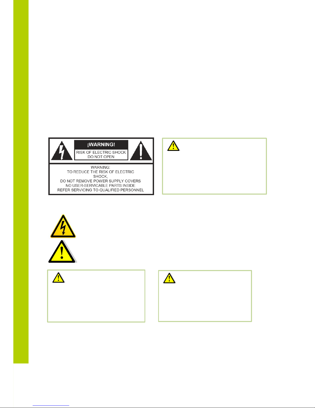
This label may appear on the bottom of the apparatus due to space limitations.
The lightning flash with an arrowhead symbol, with an equilateral triangle, is intended to alert
the user to the presence of un-insulated ‘dangerous voltage’ within the products enclosure that
may be of sufficient magnitude to constitute a risk of electric shock to persons.
The exclamation mark within an equilateral triangle is intended to alert the user to the presence
of important operating and maintenance (servicing) instructions in the literature accompanying
the appliance.
4 Confidea wireless system information
Warning:
To reduce the risk of fire or electric
shock, do not expose this appliance
to rain or moisture. Do not open the
cabinet; refer servicing to qualified
personnel only.
Warning:
To prevent electric shock, do not use
this (polarized) plug with an extension
cord receptacle or other outlet unless
the blades can be fully inserted to
prevent blade exposure.
Attention:
Installation should be performed
by qualified service personnel only
in accordance with the National
Electrical Code or applicable local
codes.
Page 11

4
Confidea wireless system information
11
4.1 General system architecture
4.1.1 Components
Confidea G3 is a wireless conference system offering conferencing capabilities over a robust
wireless link. Depending on the model, these facilities include discussion, voting and/or language
distribution.
The units (delegates/chairman) are table top units that make a wireless link to a Wireless
Conference Access Point called WCAP G3. This Access Point has a powerful built-in web server
that allows configuring and monitoring of the system from any PC or mobile device through a
standard internet browser.
4.1.2 Standalone system
A stand-alone Confidea wireless system offers basic discussion and voting. (Depending on the
model).
In this case there are no connections to other systems, except for the Confidea WCAP that
can be connected to a LAN network for monitoring and configuring.
The Confidea access point (WCAP) will in this set-up act as a small central unit, offering all
the functionality for a basic discussion application.
Page 12
12
5 Wireless network and frequency
bands
5.1 Wireless LAN
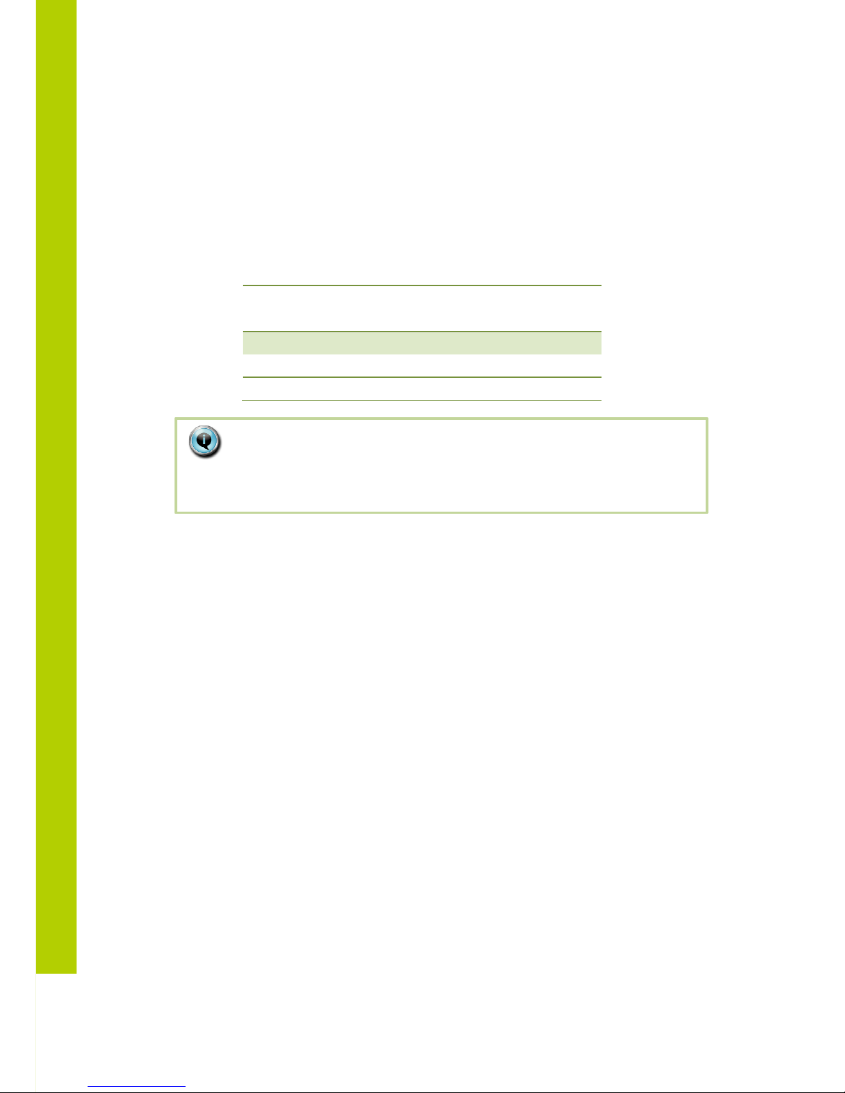
Most of the wireless local area computer networks today are based on the IEEE 802.11 a/b/g
standards. These standards were developed by the IEEE (Institute of Electrical and Electronics
Engineers) in order to insure inter-operability between different WLAN vendors.
802.11
Standard
Release
Date
Frequency
(GHz)
Maximum bit
rate
(Mbits/sec)
Modulation
type
a
1999 5 54
OFDM
b
1999
2.4
11
DSSS
g
2003
2.4
54
OFDM
Note:
The 2.4GHz and 5GHz frequency bands are license free world wide.
However you must be aware of country specific limitations and follow them.
Page 13

5
Wireless network and frequency bands
13
5.2 Televic Confidea wireless system.
The wireless network of the Televic Confidea wireless system is based on the 802.11 a/g
standards.
Additional protocols have been added on top of the 802.11 a/g standards to provide high
robustness against interference from other wireless devices. These additional protocols also
ensure a guaranteed quality of service for the audio streams on the wireless network.
5.2.1 Frequency bands
The Confidea wireless system supports the following frequency bands
ISM 2.4
GHz
RLAN
low
RLAN
high
ISM 5 GHz
2412 MHz
5180 MHz
5500 MHz
5745 MHz
2417 MHz
5200 MHz
5520 MHz
5765 MHz
2422 MHz
5220 MHz
5540 MHz
5785 MHz
2427 MHz
5240 MHz
5560 MHz
5805 MHz
2432 MHz
5260 MHz
5580 MHz
5825 MHz
2437 MHz
5280 MHz
5600 MHz
2442 MHz
5300 MHz
5620 MHz
2447 MHz
5320 MHz
5640 MHz
2452 MHz
5660 MHz
2457 MHz
5680 MHz
2462 MHz
5700 MHz
2467MHz
2472 MHz
Page 14

14
In the 2.4 GHz ISM (Industrial Scientific Medical) band, there are 13 overlapping highfrequency carriers available. Only 3 non-overlapping carriers are available.
ISM 2.4 GHz
Europe
USA
and
Canada
Japan
Korea
2412 MHz
V V V
V
2417 MHz
V V V
V
2422 MHz
V V V
V
2427 MHz
V V V
V
2432 MHz
V V V
V
2437 MHz
V V V
V
2442 MHz
V V V
V
2447 MHz
V V V
V
2452 MHz
V V V
V
2457 MHz
V V V
V
2462 MHz
V V V
V
2467MHz
V X V
V
2472 MHz
V X V
V
In the “RLAN low” frequency band, there are 8 non-overlapping wireless
carriers
RLAN LOW
Europe
USA
and
Canada
Japan
Korea
5180 MHz
V V V
V
5200 MHz
V V V
V
5220 MHz
V V V
V
5240 MHz
V V V
V
5260 MHz
V V V
V
5280 MHz
V V V
V
5300 MHz
V V V
V
5320 MHz
V V V
V
When transmitting in the 5.15-5.25 GHz band, this device is restricted to indoor use only.
Page 15

5
Wireless network and frequency bands
15
In the “RLAN high” frequency band, there are 10 non-overlapping carriers.
RLAN HIGH
Europe
USA
and
Canada
Japan
Korea
5500 MHz
V V V
V
5520 MHz
V V V
V
5540 MHz
V V V
V
5560 MHz
V V V
V
5580 MHz
V V V
V
5600 MHz
V X V
V
5620 MHz
V X V
V
5640 MHz
V X V
V
5660 MHz
V V V
X
5680 MHz
V V V
X
5700 MHz
V V V
X
In the “5 GHz ISM” frequency band, there are 5 non-overlapping carriers. All of these carriers
can be used.
5 GHz ISM
Europe
USA
and
Canada
Japan
Korea
5745 MHz
V V X
V
5765 MHz
V V X
V
5785 MHz
V V X
V
5805 MHz
V V X
V
Page 16

02
System Components
6 Wireless contribution units 16
6.1 Introduction 17
6.2 Controls and indicators 17
6.3 Installation 22
6.4 Startup and shutdown of delegate unit 22
7 Microphone 23
7.1 Introduction 23
7.2 Electrical and acoustic properties 23
7.3 Microphone connector 23
7.4 Operation 23
8 Battery pack 25
8.1 Introduction 25
8.2 Controls and indicators 25
8.3 Installation 27
9 Wireless Conference Access Point (WCAP) 28
9.1 Introduction 28
9.2 Installation 28
9.2.1 Wall Mounting 28
9.2.2 Tripod Mounting 28
9.3 Connections and Controls 29
6 Wireless contribution units
Page 17

6
Wireless contribution units
17
6.1 Introduction
The wireless contribution units, called Confidea WDU, consist of Delegate and Chairman Units.
Both are used for speech reinforcement in a conference room. The chairman units are used to
guide and control an ongoing discussion.
6.2 Controls and indicators
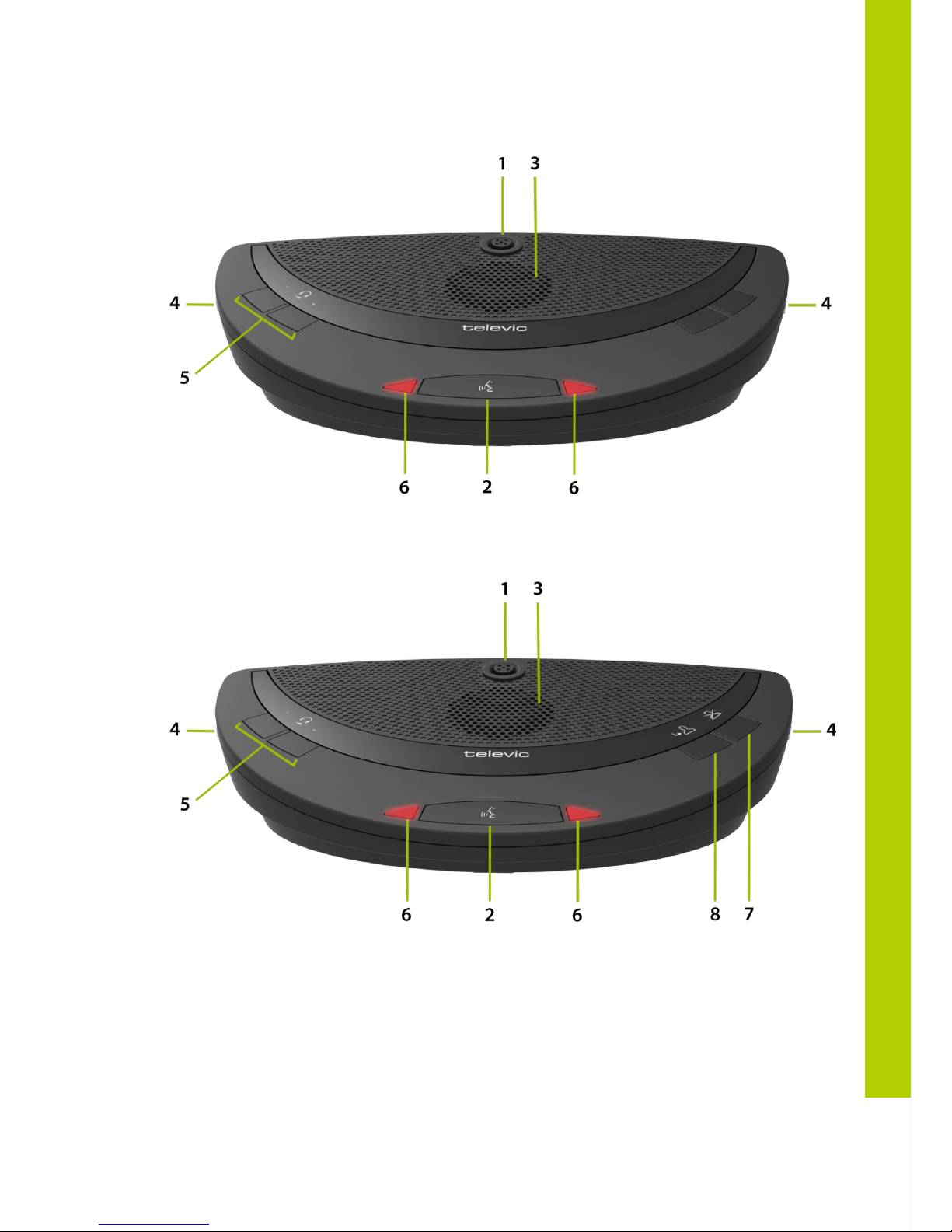
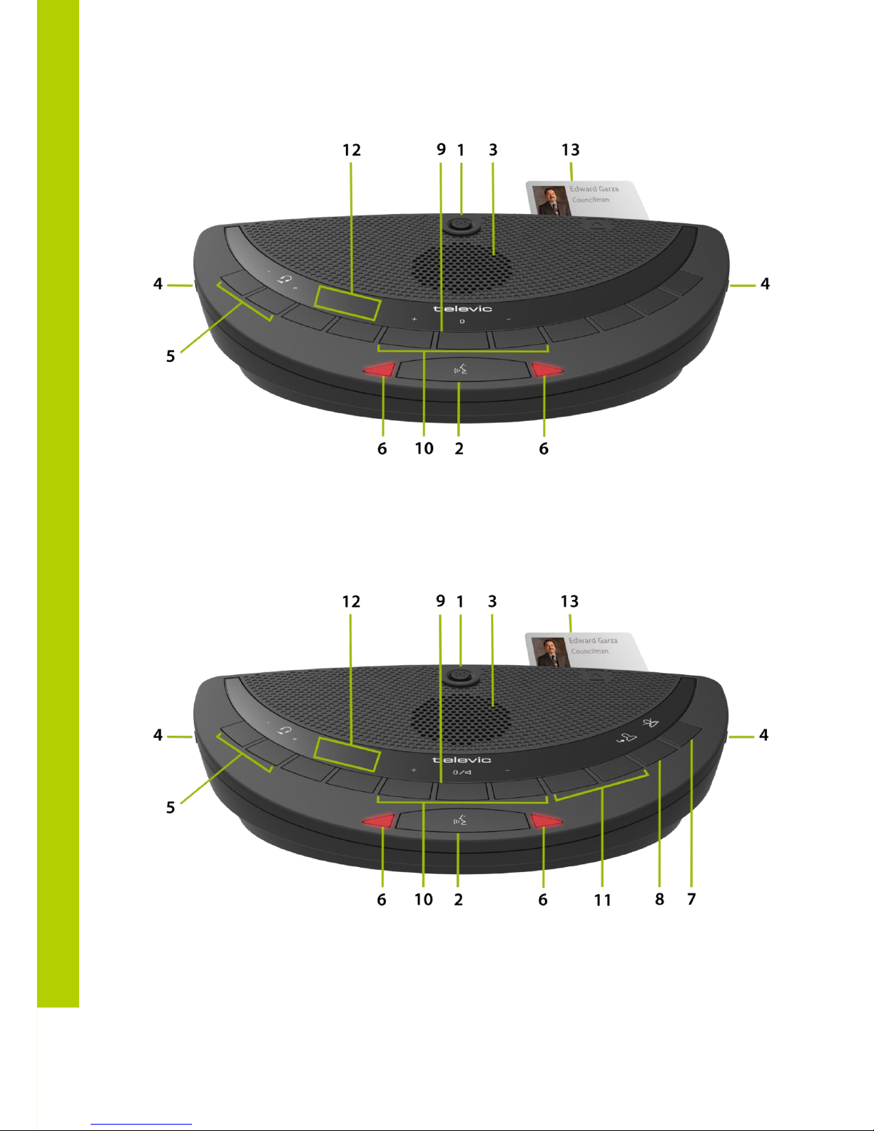
The Confidea WDU has the following features:
1. Microphone connector
Connection of a microphone to the wireless unit.
2. Microphone button
Activation/deactivation of the microphone.
3. Loudspeaker
distributes the floor channel. Mutes in case microphone is active.
4. Headphone connectors
Connection of headphone to the wireless unit. Mono- and stereo headphones can
be used.
5. Volume buttons
Change the volume level of the headphones.
6. Microphone status LEDs
Indication LEDs show the status of the microphone. (Red: active, green: request)
7. PRIOR button (Chairman Unit)
Long press: temporarily deactivates the microphone of all active units.
Short press: permanently deactivates the microphone of all active units.
8. Next button (Chairman Unit)
Grants the floor to the next delegate in the waiting list.
9. System volume control
Adjust system volume by holding the button and pressing the volume buttons.
10. Voting buttons
Each voting button has a blue LED indicator.
11. Voting control buttons
Used by the chairman to control a voting session. (Start / pause
/ stop)
12. Information display
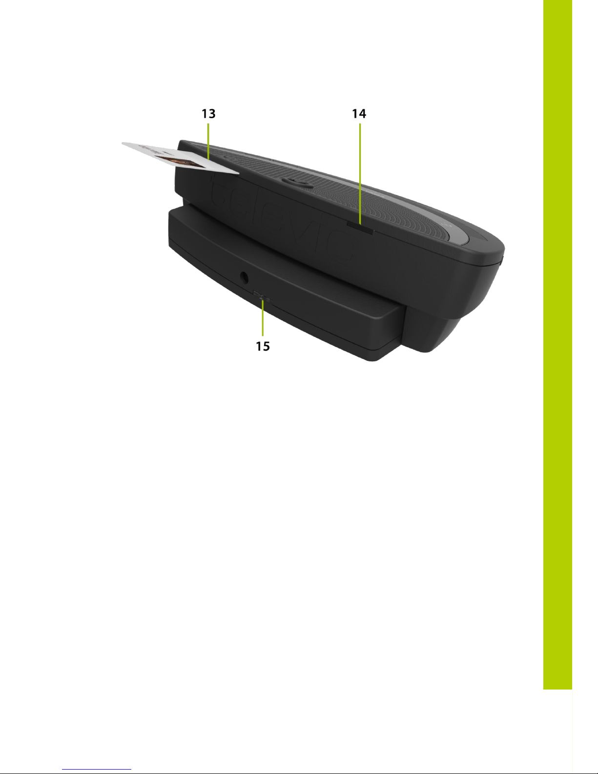
Indication of voting, volume and channel information.
13. RFID card reader
14. RF Status LEDs
Blue LED Indication of the condition of the RF connection.
Off : connection established
Blinking : searching connection
On : out of range
Page 18

18
15. Battery status LEDs
Red LED blinking the remaining operation time
1 Hz : 4h remaining
2Hz : 2h remaining
4Hz : 1h remaining
Note:
Units with the out of range LED on will be switched
off after 2 minutes.
Page 19
6
Wireless contr
ibution units
19
Confidea DD G3
Confidea CD G3
Page 20
20
Confidea DV
Confidea CV
Page 21
6
Wireless contribution units
21
Confidea Back
Page 22

22
6.3 Installation
In order to use the Confidea WDU, the battery and microphone need to be installed. For
instructions, see the microphone and battery installation and handling.
Disconnect the battery to avoid unwanted operation of the unit. Keep the devices in a clean
and dry area.
6.4 Startup and shutdown of delegate unit
To startup the delegate units simply press the microphone button for a few moments, until
the LEDs are blinking.
When units are connected to WCAP and the WCAP is switched off, the units will go to sleep
mode after +/_ 2 min, if no connection with another WCAP could be established
If the delegate units are activated they will continue to search for a connection with a WCAP,
so if no connection with a WCAP could be established, the delegate units will remain on!
To Switch off the delegate units or the WCAP needs to be deactivated to trigger automatic
sleep mode after +/_ 2 min, or batteries have to be removed
There is no switch off feature available via the delegate unit buttons
Page 23
7
Microphone
23
7 Microphone
7.1 Introduction
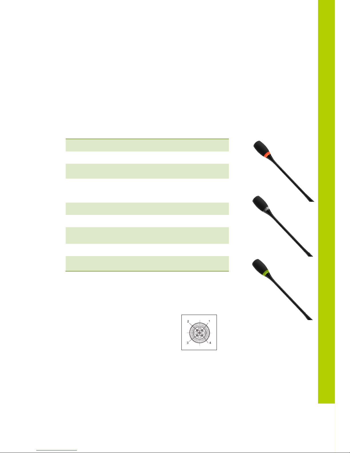
The Confidea-D MIC30SL (30 cm) - D MIC40SL (40 cm) - D MIC50SL (50 cm) pluggable
microphone is used with the different delegate- and chairman units. This microphone ha a unidirectional response for optimum performance even in noisy conditions, and has a very low
susceptibility to RF-interference from mobile phones.
7.2 Electrical and acoustic properties
7.3 Microphone connector
- pin 1 : microphone GND
- pin 2 : microphone signal
- pin 3 : unused
- pin 4 : LED +
- pin 5 : LED –
7.4 Operation
The microphone contains the following elements.
Transducer type
Back electret (condenser)
Operating principle
Pressure gradient
Polar pattern
Uni-directional,
cardioïd
Nominal impedance
Bias resistor = 1k2
Vdd = 3.3 V DC,
SPL = 1Pa
Max.SPL at 1 kHz
110 DB SPL (1% THD+N)
Signal to noise ratio
>67 dB(A)
Free field sensitivity
9.4 mV/Pa, ±3 dB @ 1 kHz or
(-40.5 dB, 0 dB = 1 V/Pa @ 1 kHz)
Power supply
3.3 V DC, 0.5 mA
Consumption
0.5 mA (without LED ring);
max. 25 mA (with illuminated ring)
Page 24

24
- Indicator ring: shows the status of the microphone
- Union nut: attaches the pluggable microphone to the unit
- Microphone plug: connects the microphone to the unit
The colour of the microphone indicator ring shows the status of the microphone.
Color
Condition
Red (on)
Microphone active
Red (flash)
Last minute of speech time (if set via
software) or Speech request (if set via
software)
Green (on)
Microphone is initialized
Green (flash)
Microphone request
Page 25
8
Battery pack
25
8 Battery pack
8.1 Introduction
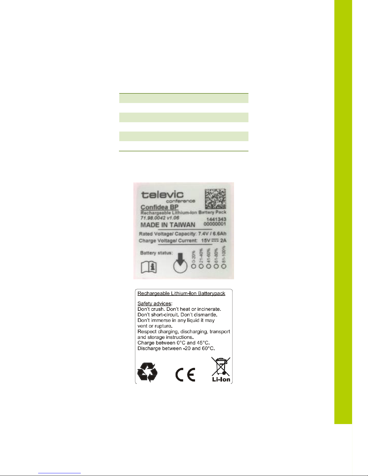
The Confidea wireless battery pack is used with the wireless conference units.
Output voltage:
7.2V
Capacity:
6600 mAh
Charge time:
4 Hours
Max charge voltage:
15V
Charge current:
2 A
Autonomy:
+ 28 Hours (Typical)
8.2 Safety
Page 26
26
8.2.1 Power supply
15V / 2A
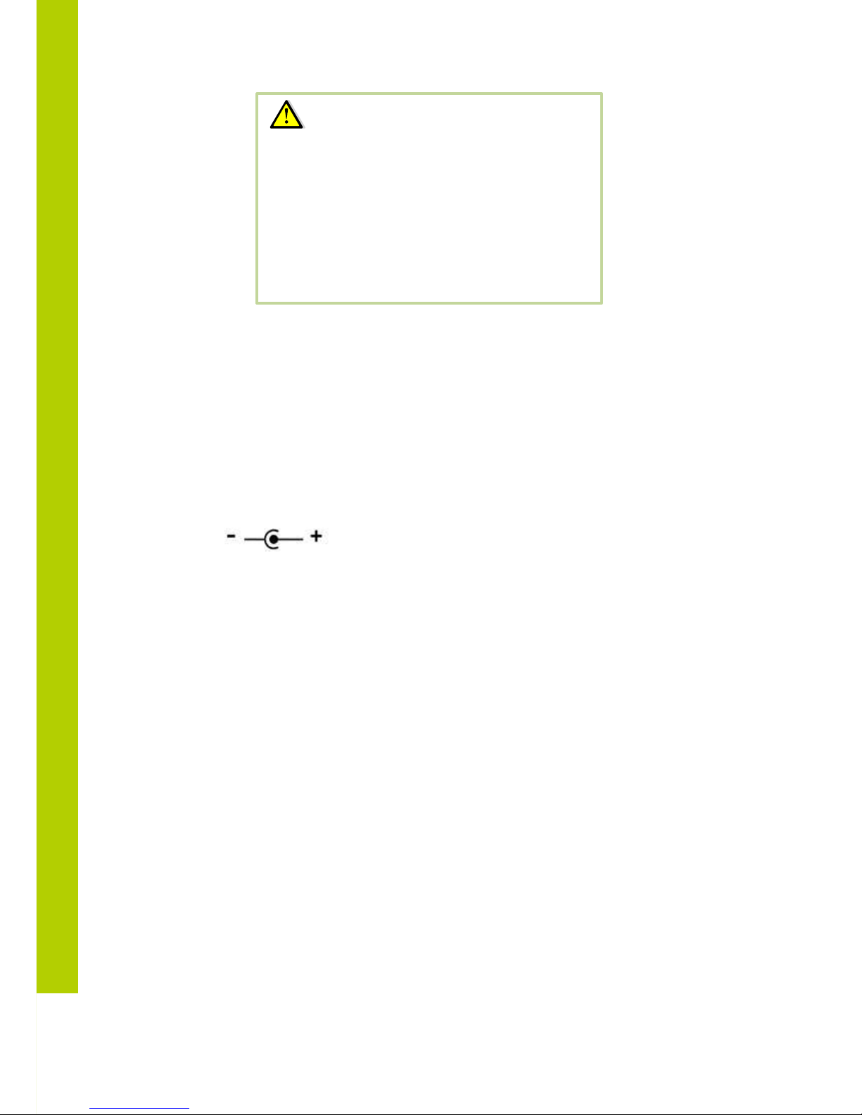
DC power plug: outer diameter: 5.5mm
Inner diameter: 2.1mm
Polarity:
8.3 Controls and indicators
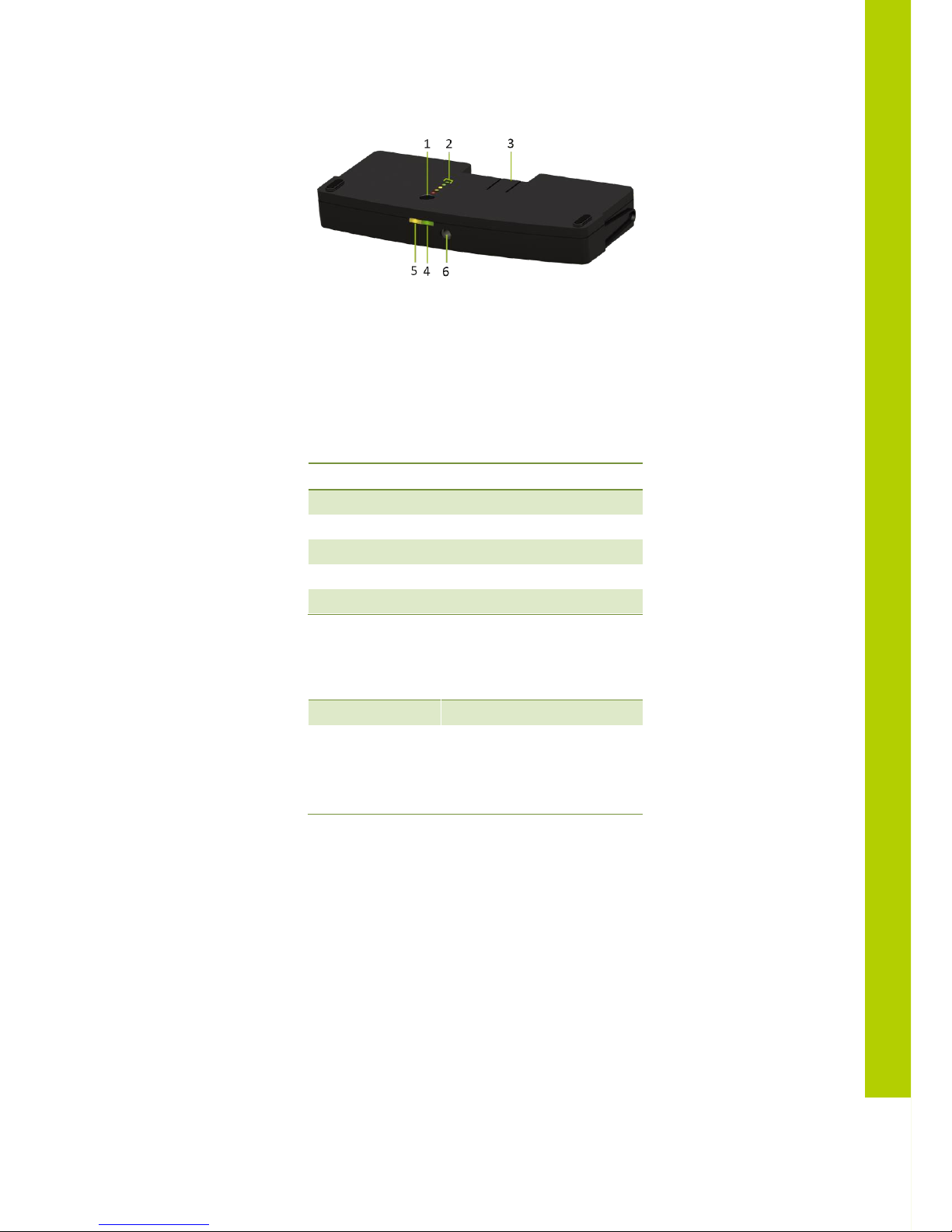
The battery pack contains:
1. Test button
Push to check the capacity and the status of the battery pack.
2. Capacity and status indicator
Shows the capacity of the battery pack
3. Clip
Locks/unlocks the battery pack in the wireless unit.
4. Power LED
indicates that the charger is connected and powered.
5. Charging LED
Indicates the charging status (in progress or completed) when the wall plug battery
charger is connected.
6. Socket
to connect the charger plug.
Warning:
Danger of explosion if the battery pack is incorrectly
replaced
Replace with the same or equivalent type
Do not use or leave the battery pack at very high
temperature conditions (e.g. strong direct sunlight or a
vehicle in extremely hot conditions)
Do not throw the battery pack into fire
Page 27
8
Battery pack
27
8.4 Installation
Install a charged battery pack in a compatible device. To check the condition of the battery
pack, push the test button 1.
The indicator is a five segment LED. The first LED (LED1 closest to the test button) is red and
indicates a low capacity battery. The higher the charge, the higher the number of LEDs that light
up.
LED on
Remaining charge
LED 1 (red)
0-20%
LED 2 (orange)
20-40%
LED 3 (orange)
40-60%
LED 4 (green)
60-80%
LED 5 (green)
80-100%
After the display of the battery condition (for 4-5 seconds), the first three LEDs (LED1 to LED3)
will indicate the status of the charge circuitry.
LED 3 is flashing:
Charging circuitry is ok
All other
indications:
Indicates a failure
Disconnect the charger from
the battery pack and remove
the battery pack from the
conference unit.
Page 28
28
9 Wireless Conference Access Point
(WCAP)
9.1 Introduction
All communication to and from the wireless units is controlled by the WCAP.
9.2 Installation
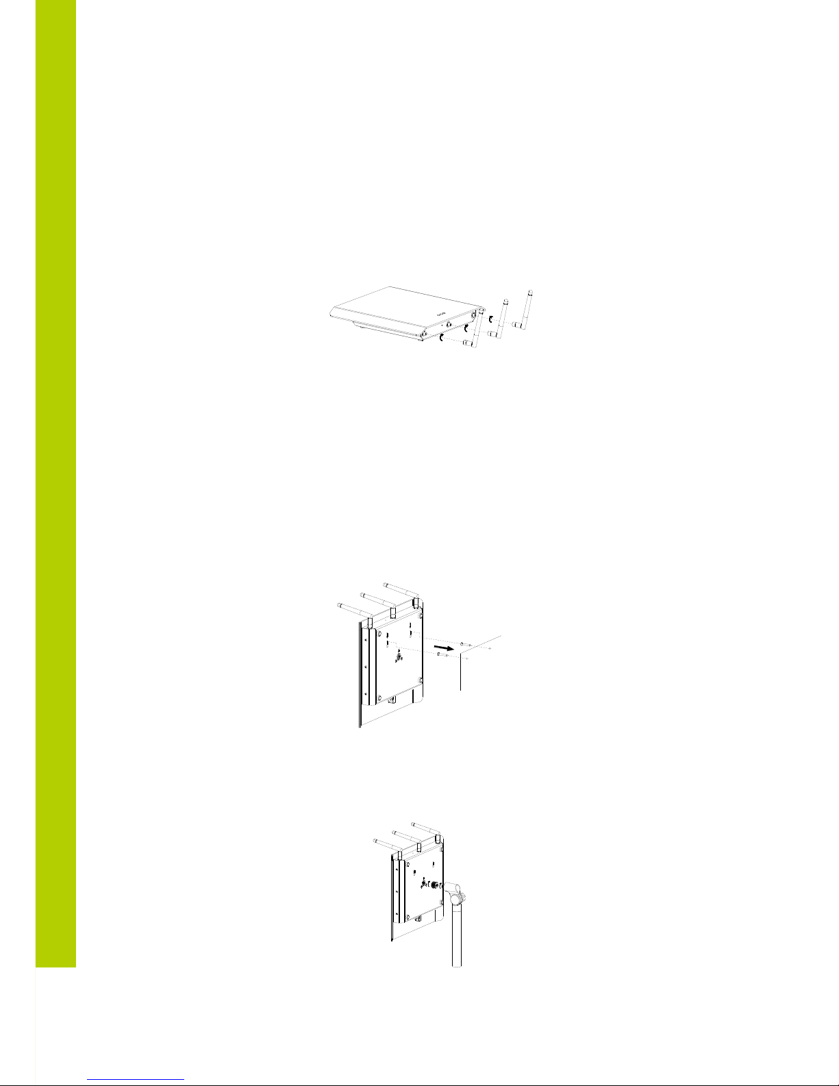
9.2.1 Wall Mounting
The WCAP can be mounted on the wall by means of the 2 fixing holes at the bottom side of
the device
To prevent accident, this device must be securely attached to the wall in accordance with the installation
instructions.
9.2.2 Tripod Mounting
The WCAP can also be mounted on a tripod.
Page 29
9
Wireless Conference Access Point (WCAP)
29
9.3 Connections and Controls
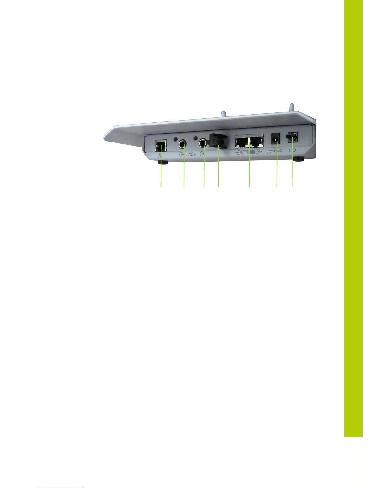
1. Power Switch
The WCAP can be switched on/off with the power switch at the back of the WCAP.
2. Power Supply
The power supply of the WCAP is provided by a 110 - 230VAC/24VDC adaptor
3. Digital Bus Connection
Connection with the uniCOS conference buts is done through RJ45 – connectors at
the back of the WCAP
4. Cable retention clip
The cable retention clip is used to safeguard the cable of the power adaptor
5. LAN port
Through the LAN connector at the back of the WCAP, a PC can be connected using
a standard cat. 5e FTP network cable.
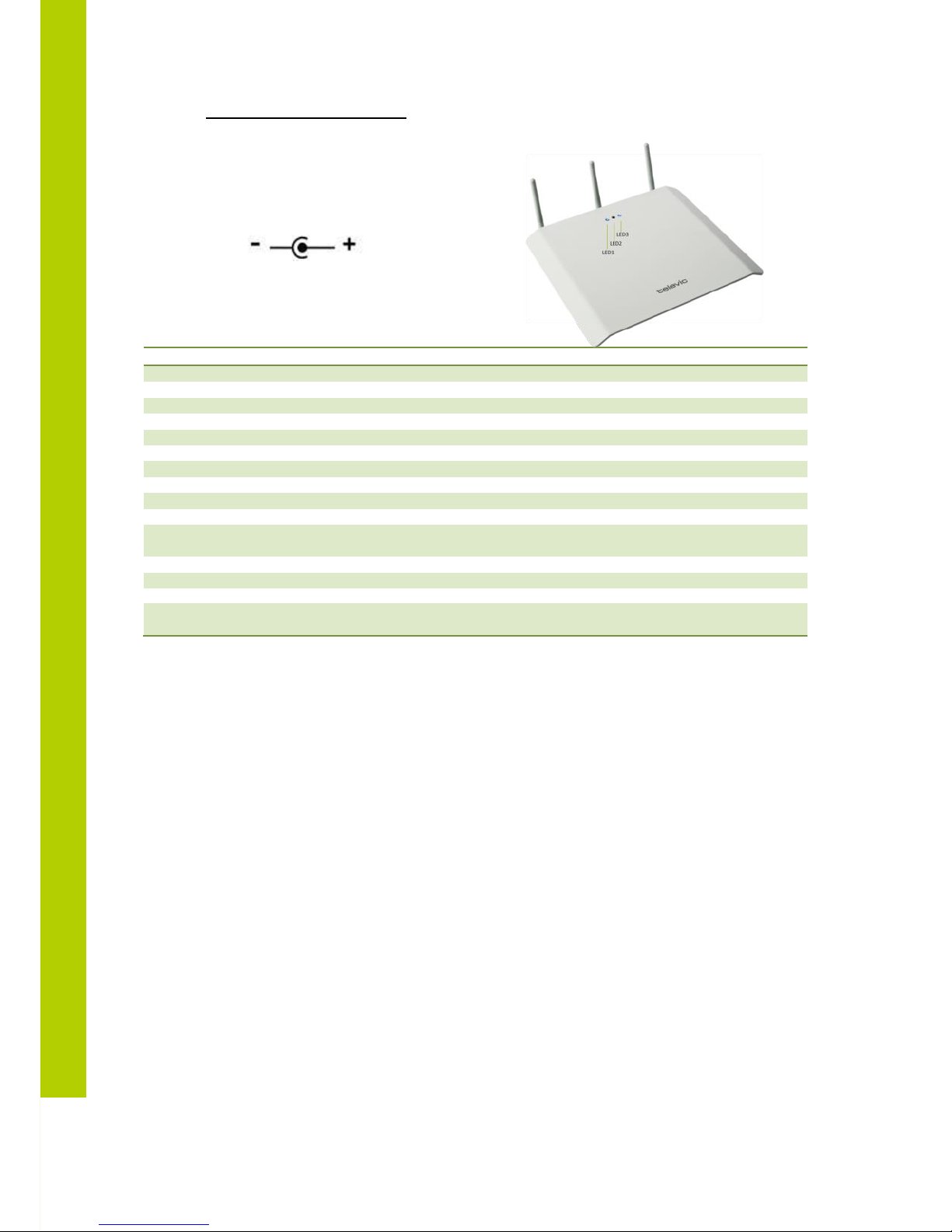
6. Status LEDS
The status LEDs give information on selected mode, RF link quality (Signal/Noise
Ratio) and delegate unit detection
7. Aux input
Auxiliary balanced output connector
8. Aux
9. output
Auxiliary balanced input connector
2 1 3 4 5 8 7
Page 30
30
Specifications of th ACDC adapter:
24V / 0.625A
DC power plug: outer diameter: 5.5mm
Inner diameter: 2.1mm
Polarity:
LED1
LED2
LED3
Meaning
White
Boot sequence started
Blinking red
Unitialized golden mode
Fixed red
Initialized golden
Blinking green
Unitialized application
Fixed Green
Initialized application
Fixed green
Connected with uniCOS
Blinking red
Connection error
Blinking green
Connecting with uniCOS
Off Standalone
Blinking white
Update in progress
Red
Transmission
error/Retransmit
Green
Packet transmit
Off
Idle
Blinking red, green,
blue
Blinking red, green, blue
Blinking red, green, blue
Test mode
Remark:
At startup, the transition from boot sequence started (blinking white led) to application mode started (blinking
green) is very short and so the short red led activation in between might even not be noticed
 Loading...