

Page 1

TV & SAT Level Meter User´s manual
MTD 120
Ref. 4202
(Color)
Ref. 4207 (B/N)--
(Bit Error Rate)
BER
Page 2

103
ENGLISH
TV & SAT Level Meter MTD 120 User Manual
INDEX ................................................................................................................................. Page
1.- GENERAL .............................................................................................................................................. 105
1.1.- Description ..................................................................................................................................... 105
1.2.- Specifications ................................................................................................................................. 106
2.- SAFETY RULES ..................................................................................................................................... 110
3.- INSTALLATION ....................................................................................................................................... 111
3.1.- Power Supply ................................................................................................................................ 111
3.1.1.- Operation using the External DC Adapter ............................................................................ 111
3.1.2.- Operation using Batteries ..................................................................................................... 111
3.1.2.1.- Battery Charging .......................................................................................................... 111
3.2.- Installation and Start-up ................................................................................................................. 111
4.- OPERATING INSTRUCTIONS .............................................................................................................. 112
4.1.- Description of the Controls and Elements ..................................................................................... 112
4.2.- Adjustment of Volume and Monitor Parameters ........................................................................... 116
4.3.- Selecting the Operation Mode: TV / Spectrum Analyser ............................................................... 116
4.4.- RF Band Selection: 5-862 MHz / 920-2150 MHz .......................................................................... 116
4.5.- Channel Tuning / Frequency Tuning ............................................................................................. 116
4.6.- Automatic Transmission Search .................................................................................................... 116
4.7.- Selecting Analogue / Digital Mode ................................................................................................. 116
4.8.- External Units Power Supply (EXT. SUPPLY) .............................................................................. 117
4.9.- TV Operating Mode ....................................................................................................................... 118
4.9.1.- Selecting the Measurement Mode (MEASURE) .................................................................. 118
4.9.1.1.- Measuring the Video Carrier Level (Level) .................................................................. 119
4.9.1.1.1.- On-screen Measurement Information ................................................................. 119
4.9.1.1.2.- Selecting TV Mode: TV, LV, SY (TV MODE) ...................................................... 119
4.9.1.2.- Measuring the Video / Audio Ratio (V/A) ..................................................................... 120
4.9.1.3.- Measuring the Carrier / Noise Ratio (C/N) ................................................................... 121
4.9.1.4.- Measuring the Power of Digital Channels (Channel power) ........................................ 122
4.9.2.- TV Mode Functions Menu .................................................................................................... 123
4.9.2.1.- Selection of the RF Band: (Band switching) ................................................................ 123
4.9.2.2.- Selection of the TV System and Standard (System & Standard) ................................ 123
4.9.2.3.- Batteries and External Units Power Supply (Battery & Lnb) ........................................ 124
4.9.2.4.- Data Logger Function .................................................................................................. 124
4.9.2.4.1.- Configuring the Data Logger Function ................................................................ 125
4.9.2.4.2.- Selecting the Measurements to be Taken .......................................................... 127
4.9.2.4.3.- Taking Measurements ......................................................................................... 127
4.9.2.4.4.- Exiting the Data Logger Function ........................................................................ 127
4.9.2.4.5.- Examples of Data Logger Function Applications ................................................ 127
4.9.2.5.- Clock ............................................................................................................................ 128
4.9.2.6.- Input Video ................................................................................................................... 128
4.9.2.7.- Selecting the Channels Table (Channel set) ............................................................... 128
4.9.2.8.- Measurement Units ...................................................................................................... 128
4.9.2.9.- Power Off Mode (Manual power) ................................................................................. 128
4.9.2.10.- C/N setup ................................................................................................................... 129
4.9.2.11.- Channel Bandwidth (Channel BW) ............................................................................ 129
4.9.2.12.- LNB Local Oscillator Frequency (Lnb local osc) ........................................................ 129
4.9.2.13.- Video Polarity ............................................................................................................. 129
4.9.2.14.- NICAM Channel ......................................................................................................... 129
Page 3

4.9.2.15.- Search Level .............................................................................................................. 129
4.9.2.16.- Teletext ...................................................................................................................... 129
4.9.2.17.- DiSEqC Command Generator ................................................................................... 130
4.9.2.18.- Beep ........................................................................................................................... 131
4.9.2.19.- Equipment Information ............................................................................................... 131
4.9.2.20.- Exit ............................................................................................................................. 131
4.10.- Spectrum Analyser Operating Mode ........................................................................................... 132
4.10.1.- Spectrum Analyser Mode Functions Menu ........................................................................ 132
4.10.1.1.- Band Switching ........................................................................................................... 133
4.10.1.2.- Span ........................................................................................................................... 133
4.10.1.3.- Reference Level ......................................................................................................... 133
4.10.1.4.- Dual Marker/Single Marker ........................................................................................ 133
4.10.1.5.- Sweep ........................................................................................................................ 133
4.10.1.6.- Reference Noise ........................................................................................................ 134
4.10.1.7.- Channel Bandwidth .................................................................................................... 134
4.10.1.8.- Marker ........................................................................................................................ 134
4.10.1.9.- Carrier ........................................................................................................................ 134
4.10.1.10.- Bandwidth of the Spectrum Measuring Filter (Measure bandwidth) ........................ 134
4.10.1.11.- Selecting the Channels Table (Channel set) ........................................................... 134
4.10.1.12.- Batteries and External Units Power Supply (Battery & Lnb) .................................... 134
4.10.1.13.- Exit ........................................................................................................................... 134
4.10.2.- Selecting the Measurement Mode ...................................................................................... 135
4.10.2.1.- Measuring Carrier Levels (Level) ............................................................................... 135
4.10.2.2.- Measuring the Carrier / Noise ratio (C/N Referenced) .............................................. 135
4.10.2.3.- Measuring the Power of Digital Channels (Channel Power) ..................................... 136
4.11.- Selecting the Sound Mode (Sound) ............................................................................................ 137
4.12.- Measurement Configuration Memories ....................................................................................... 138
4.12.1.- Storing a Measurement Configuration (STORE) ................................................................ 138
4.12.2.- Retrieving a Configuration (RECALL) ................................................................................ 138
4.13.- Direct Access to Functions ......................................................................................................... 139
4.14.- Printing Measurements and Memories ........................................................................................ 139
4.14.1.- Handshake and Control Lines ............................................................................................ 140
5.- BER MEASURES ................................................................................................................................... 141
5.1.- Description ..................................................................................................................................... 141
5.2.- BER measurement mode selection ............................................................................................... 141
5.3.- QAM modulation ............................................................................................................................ 141
5.4.- QPSK modulation .......................................................................................................................... 143
5.5.- COFDM modulation ....................................................................................................................... 145
5.6.- DVB Channels Identifier ................................................................................................................ 148
6.- DESCRIPTION OF THE INPUTS AND OUTPUTS ............................................................................... 149
6.1.- RF input ......................................................................................................................................... 149
6.2.- RS-232C serial port ....................................................................................................................... 149
6.3.- Scart (DIN EN 50049) .................................................................................................................... 150
7.- MAINTENANCE ..................................................................................................................................... 151
7.1.- Considerations about the Screen .................................................................................................. 151
7.2.- Internal fuses which user cannot replace ..................................................................................... 151
7.3.- Replacing the Batteries ................................................................................................................. 151
7.4.- Cleaning Recommendations ......................................................................................................... 152
APPENDIX A: Channel-Frequency Tables .................................................................................................. 153
104
TV & SAT Level Meter MTD 120 User Manual
Page 4
105
ENGLISH
TV & SAT Level Meter MTD 120 User Manual
1.- GENERAL
1.1.- Description
The result of uniting long experience in the design of TV signal analysers with the latest in technological progress, the MTD 120 brings
together the functions installers seek most, all in one small, light-weight, portable instrument.
The range of frequencies covered, from 5 to 862 MHz and from 920 to 2150 MHz, makes MTD 120 an excellent instrument for FM radio,
terrestrial TV, cable TV (CATV, 'Community Antenna Television', where the subband tuning margin, from 5 to 45 MHz, enables the user to
carry out tests on the return channel), satellite TV, MMDS microwave links, VSAT ('Very Small Aperture Terminal') systems, digital TV and
intermediate frequency analysis (38.9 MHz). Furthermore, its high resolution frequency, 50 kHz, makes FM measurements much easier.
The MTD 120 includes the main TV standards: M, N, B, G, I, D, K and L, adopting, apart from the characteristic parameters of the
standard, the correcting automatic system to obtain in all the cases an accurate measuring of the input signal level. It admits any TV system
(PAL, SECAM and NTSC) and allows the user to work directly with digital TV signals for which it provides directly the measuring of power
and carrier-to-noise ratio (C/N). Being a multistandard instrument, it can be efficiently used in any country of the world. Its accuracy and
reliability meet the needs of the most demanding users.
A powerful microprocessor automatically handles a large part of the operations necessary to optimise the process of measurement; for
example, continuous frequency synthesis, measurement correction, the appropriate selection of the attenuators and the automatic cut-off after
the device has been inactive for a certain period of time.
The signal level measured is indicated numerically in absolute values and, optionally, on an analogue bar shown superimposed on the
monitor image, that facilitates the detection of the maximum level. Moreover, in the LV sound mode, the loudspeaker emits a tone whose
frequency depends on the level of the signal received, which is very useful when installing antennas. It is also possible to display on screen
the line synchronism pulse like on an oscilloscope screen.
The Spectrum Analyser mode enables all the signals on a band to be viewed on the monitor at the same time to measure analogue
channels level, C/N ratio referenced to a noise frequency defined by the user and digital channels power using an integration method. The
bandwidth of the measuring filter can be modified to improve frequency resolution. This is an indispensable feature, as high channel density is
present on all transmission systems today. Spectrum display can be varied between full span (the entire band) and 8 MHz terrestrial or 32
MHz satellite. In addition, there are two markers in order to locate and list frequencies, to read signal level and frequency difference, and the
level between both.
The selection of sound subcarrier is automatic, depending on the standard, or tunable between 4 and 9 MHz. When decoding TV sound it
is possible to choose between the NARROW and WIDE filter to obtain the best carrier discrimination. It includes a NICAM decoder (with BER
measurement); the possibility to commute the channel that is delivered to the loudspeaker enables the user to check the sound stereo and
dual.
To enhance its convenience of use, it has 99 memories to store the different measuring configurations: name of the confi guration,
frequency, TV system, type of measurement, external units powering, units of measurement and sound. Moreover, the DATALOGGER
function permits the acquisition and storage of up to 9801 measures (99 confi gurations x 99 points of measure) that makes it much easier to
test systems in which a large number of measurements have to be made, and enables further processing of all the information acquired.
Also, the level meter incorporates the teletext function, a DiSEqC command generator and permits to supply different voltages to the
external unit (13 V / 15 V / 18 V / 24 V terrestrial TV, and 13 V / 15 V / 18 V / 13 V + 22 kHz / 15 V + 22 kHz / 18 V + 22 kHz satellite TV).
A SCART connector has been also included with input/output of audio/video.
The MTD 120 is powered by rechargeable batteries or connected to the mains through the supplied external DC power adapter.
It also incorporates a RS-232C interface which enables the user to connect the instrument to a PC for data recording, remote-control of
the instrument and to a printer in order to print out the measurements.
SAFETY NOTES
Read the instruction manual before using the equipment, mainly " SAFETY RULES " paragraph.
The symbol on the equipment means "SEE INSTRUCTION MANUAL".
In this manual may also appear as a Caution or Warning symbol.
Warning and Caution statements may appear in this manual to avoid injury hazard
or damage to this product or other property.
(*)
DiSEqC™ is a trademark of EUTELSAT.
Page 5

1.2.- Specifications
TUNING Digital frequency synthesis. Continuous tuning from 5 to 862 MHz and from 920 to 2150 MHz
Tuning modes Frequency, Channel or Memory. Channel plan configurable on demand
Resolution 50 kHz
Automatic search Threshold level selectable
Memory 99 positions for measurement configurations
RF INPUT
Frequency range
QAM signals 47 MHz to 862 MHz
QPSK signals 950 MHz to 2150 MHz
COFDM signals 470 MHz to 862 MHz
Level range
QAM signals 45 dBµV to 110 dBµV
QPSK signals 44 dBµV to 99 dBµV
COFDM signals 45 dBµV to 100 dBµV
Impedance 75 Ω
Connector Universal, with BNC or F adapter
Maximum signal 130 dBµV
Maximum input voltage
DC to 100 Hz 50 V rms (powered by the power adapter)
30 V rms (not powered by the power adapter)
5 MHz to 2150 MHz 130 dBµV
LEVEL MEASUREMENT
Measurement range
Terrestrial TV & FM bands 20 dBµV to 130 dBµV (10 µV to 3.16 V)
Satellite TV band 30 dBµV to 120 dBµV (31.6 µV to 1 V)
Reading Auto-range, reading is displayed on an OSD window
Digital Absolute value calibrated in dBµV, dBmV or dBm
Analogue Relative value through an analogue bar on the screen
Measurement bandwidth 230 kHz (Terrestrial band) • 4 MHz (Satellite band) (maximum band ripple 1 dB).
Audible indicator LV audio. A tone with pitch proportional to signal strength.
Accuracy
Sub-band ± 2.5 dB (50-120 dBµV, 5-45 MHz)(22ºC ± 5ºC)
Terrestrial bands ± 1.5 dB (30-120 dBµV, 48,25-861 MHz)(22ºC±5ºC)
Satellite band ±1.5 dB (40-100 dBµV, 920-2050 MHz)(22ºC ±5ºC)
Overrange indication
vI , I
^
BER MEASUREMENT
QAM signals
Measurement BER before FEC (Forward Error Correction). Number of non correctable packets received in the
measurement time.
Reading Numerical and level bar.
QPSK signals
Measurement BER before Viterbi
BER after Viterbi
Number of non correctable packets received in the measurement time.
Reading Numerical and level bar.
COFDM signals
Measurement BER after Viterbi
CSI (Channel Status Information). Qualitative measurement about channel quality. Readout between
0 and 100%, the 0 % value corresponds to maximum quality.
Number of wrong packets received in the measurement time.
Reading Numerical and level bar.
106
TV & SAT Level Meter MTD 120 User Manual
Page 6

107
ENGLISH
TV & SAT Level Meter MTD 120 User Manual
DCI FUNCTION DVB Channel Identifier. It provides information about the channel we are making the measurement.
QAM SIGNAL PARAMETERS
Demodulation 16 / 32 / 64 / 128 / 256 QAM
Symbol rate 1000 to 7000 kbauds
Symbol Rate acquisition range ± 240 ppm
Carrier frequency offset ± 0,08 x Symbol rate
Nyquist filter roll-off(α) 0,15
Spectral inversion Selectable: On, Off
Equivalent noise degradation < 1,5 dB
QPSK SIGNAL PARAMETERS
IF bandwidth 55 MHz
Symbol rate 23000 to 30000 kbauds
4000 to 30000 kbauds for channel spacing frequency ≥ 29.5 MHz
Symbol Rate acquisition range ± 70 ppm
Carrier frequency offset ± 0,1 x Symbol rate
Nyquist filter roll-off (α) 0,35
Code rate 1/2, 2/3, 3/4, 4/5, 5/6, 6/7, 7/8, 8/9 and Auto.
Spectral inversion Selectable: On, Off and Auto except for the following values of Code Rate: 4/5, 5/6, 6/7 and 8/9.
Equivalent noise degradation < 1 dB
COFDM SIGNAL PARAMETERS
Carriers 2k / 8k (user definable)
Guard Interval 1/4, 1/8, 1/16, 1/32 (user definable)
Code Rate 1/2, 2/3, 3/4, 5/6, 7/8
Modulation QPSK, 16QAM, 64QAM
Spectral inversion On/off
Hierarchy
FEC Reed-Solomon (204,188) and Viterbi
MEASUREMENTS IN TV MODE
Terrestrial bands
Analogue channels Level, Video-Audio ratio and Carrier-Noise ratio (Auto and Referenced).
Digital channels Channel power (Auto) and Carrier-Noise ratio (Auto and Referenced).
Satellite band
Analogue channels Level and Carrier-Noise ratio (Auto and Referenced)
Digital channels Channel power (Auto) and Carrier-Noise ratio (Auto and Referenced).
DATA LOGGER function Automatic acquisition of up to 9801 measurements
SPECTRUM ANALYSER MODE
Satellite band 30 dB µV to 120 dBµV (31.6 µV to 1 V)
Terrestrial bands 20 dBµV to 130 dBµV (10 µV to 3.16 V)
Measurement bandwidth
Terrestrial 230 kHz, 1 MHz selectable
Satellite 230 kHz, 4 MHz selectable
Span
Terrestrial Full span (full band), 500, 200, 100, 50, 32, 16, 8 MHz selectable.
Satellite Full span (full band), 500, 200, 100, 50, 32 MHz selectable.
Markers 2 with level, frequency, level difference and frequency difference indications.
Measurements
Terrestrial bands
Analogue channels Level and Carrier-Noise ratio (Referenced)
Digital channels Channel power (Integration method) and Carrier-Noise ratio (Referenced).
Satellite band
Analogue channels Level and Carrier-Noise rate (Referenced)
Digital channels Channel power (Integration method) and Carrier-Noise ratio (Referenced).
Page 7

MONITOR DISPLAY
Monitor LCD colour 4 inches (ref. 4202)
Black & White 4 1/2 inches (ref. 4207)
Colour system PAL, SECAM and NTSC
TV standard M, N, B, G, I, D, K and L
Synchronism and Burst Graphic representation over the picture
Spectrum mode Variable span and reference level
Sensibility 40 dBµV for correct synchronism
Synchronism 50/60 Hz Automatic selection according to the system
VIDEO SIGNAL
External video input Scart (automatic)
Sensibility 1 Vpp (75) positive video
Video output Scart (75)
SOUND
Input Scart
Outputs Built in speaker, Scart
Demodulation AM, FM, TV and NICAM, selectable
De-emphasis 50 µs
Subcarrier Digital frequency synthesis
Variable From 4 to 9 MHz, 10 kHz resolution
Fixed
Terrestrial According to the active standard: 4.50 - 5.50 - 5.80 -6.00 - 6.50 - 6.65 - 5.74 - AM - FM - LV - OFF.
Satellite 6.65 - 5.80 - 6.50 - 7.02 - LV - OFF
TELETEXT Decodes at 1.5 level
RS-232C INTERFACE
EXTERNAL UNITS POWER SUPPLY Through the RF input connector
Terrestrial External or 13/15/18 V
Satellite External or 13/15/18 V
22 kHz signal Selectable
Voltage 0.6 V ± 0.2 V
Frequency 22 kHz ±4 kHz
Maximum power 5 W
DiSEqC GENERATOR
(*)
According to DiSEqC 1.2 standard
POWER SUPPLY
Internal
Batteries 2 x 6 V 3.3 Ah lead acid batteries
Autonomy > 1 hour non stop
Recharging time 12 h starting from a complete discharge
External
Voltage 12 V
Consumption 42 W
Auto power off After 15 minutes without operating on any control. Deactivable.
OPERATING ENVIRONMENTAL CONDITIONS
Altitude Up to 2000 m
Temperature range From 5 to 40 º C
Max. relative humidity 80 % (up to 31ºC), decreasing lineally up to 50% at 40º C.
(*)
DiSEqC™ is a trademark of EUTELSAT.
108
TV & SAT Level Meter MTD 120 User Manual
Page 8

109
ENGLISH
TV & SAT Level Meter MTD 120 User Manual
MECHANICAL FEATURES
Dimensions 280 (W) x 95 (H) x 250 (D) mm
Weight 5,2 kg
INCLUDED ACCESSORIES
Rechargeable battery 6 V, 3.3 Ah
"F"/F-BNC/F adapter
"F"/F-"DIN"/F adapter
"F"/F-"F"/F adapter
External DC adapter
Carrying bag
NOTE: BER measurement options of QPSK, QAM or COFDM modulated signals vary based on the model of used Measurer.
Page 9
2.- SAFETY RULES
* Use this equipment connected only to systems with their negative of measurement connected to ground potential.
* The external DC adapter is a Class I equipment, for safety reasons plug it to a supply line with the corresponding ground terminal.
* This equipment can be used in Overvoltage Category II installations and Pollution Degree 2 environments.
* When using some of the following accessories use only the specified ones to ensure safety:
Rechargeable batteries
External DC adapter
* Observe all specified ratings both of supply and measurement.
* Remember that voltages higher than 60 V DC or 30 V AC rms are dangerous.
* Use this instrument under the specified environmental conditions.
* The user is only authorized to carry out the following maintenance operations:
Batteries replacement
On the Maintenance paragraph the proper instructions are given.
Any other change on the equipment should be carried out by qualified personnel.
* When using the power adaptor, the negative of measurement is at ground potential.
* Do not obstruct the ventilation system of the instrument.
* Use for the signal inputs/outputs, specially when working with high levels, appropriate low radiation cables.
* Follow the cleaning instructions described in the Maintenance paragraph.
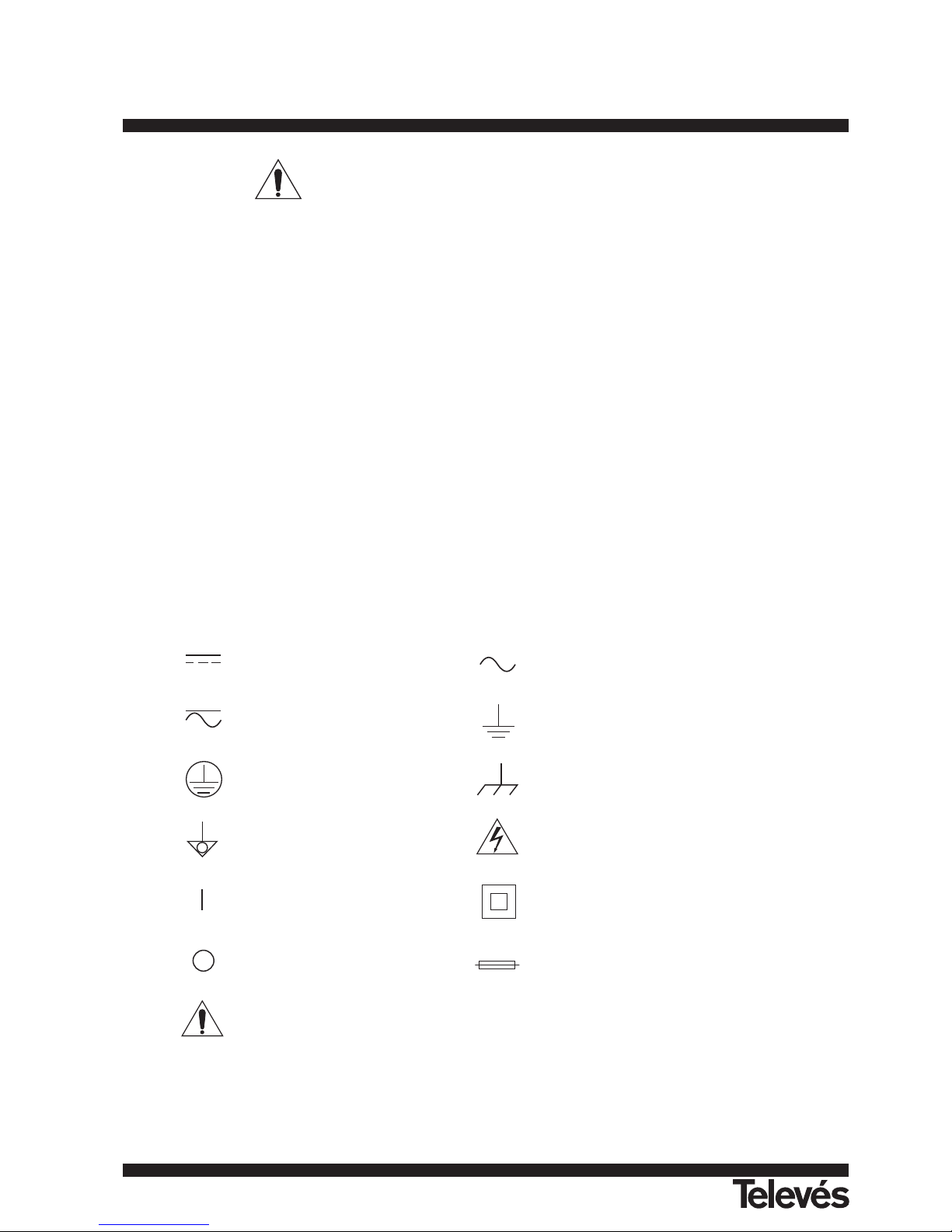
* Symbols related with safety:
DIRECT CURRENT ALTERNATING CURRENT
DIRECT AND ALTERNATING GROUND TERMINAL
PROTECTIVE CONDUCTOR FRAME TERMINAL
EQUIPOTENTIALITY CAUTION (Risk of electric shock)
ON (Supply) DOUBLE INSULATION (Class II Protection)
OFF (Supply) FUSE
CAUTION REFER TO MANUAL
110
TV & SAT Level Meter MTD 120 User Manual
Page 10

111
ENGLISH
TV & SAT Level Meter MTD 120 User Manual
3.- INSTALLATION
3.1.- Power Supply
The MTD 120 is a portable instrument powered by two 6 V - 3.3 Ah lead acid batteries. There is also an external DC adapter provided for
mains connection and battery charging.
3.1.1.- Operation using the External DC Adapter
Connect the external DC adapter to EXT. SUPPLY [38] on the MTD 120 side panel. Connect the DC adapter to the mains. Then, press
the MTD 120 on/off key [2] The level meter is now in operation and the batteries are slowly charged. When the instrument is connected to
the mains, the CHARGER indicator [7] remains lit.
3.1.2.- Operation using Batteries
For the device to operate on the battery, disconnect the power cable and press the on/off key [2]. The fully charged battery can power
the equipment for more than 1 hour non-stop.
If batteries are very weak, the battery cut-off circuit will prevent the device from functioning at the same time the beeper will be heard. In
such a situation batteries must be recharged immediately.
Before taking any measurements, you have to check the charge state of the batteries by checking the battery charge level indicator
BATTERY OK [8] on the front panel, or Battery & Lnb function on the TV mode functions menu (see section '4.9.2.3 Batteries and External
Units Power Supply').
The BATTERY OK [8] led indicates the battery charge state. For battery charge levels close to 100% and if the unit is powered by the
external power adapter, it remains lit. For battery levels between 100% and low battery it starts to fl icker, gradually fading as the charge level
decreases. On reaching Low Battery, it ceases to light up at all. When the instrument indicates a Low Battery (the led does not light up) the
batteries must be charged immediately. When the low battery level is reached, the monitor momentarily displays the message VERY LOW
BATTERY and the beeper sounds.
3.1.2.1.- Battery Charging
To fully charge the batteries, connect the instrument to the external DC adapter without pressing the on/off key [2]. The length of
time it takes to recharge it depends on the condition of the battery. If they are very low the recharging period is about 12 hours. The
CHARGER [7] indicator should remain lit.
IMPORTANT
If batteries are completely discharged, it is advisable to recharge them for a period of one hour before putting the instrument into
operation again. In these circumstances it is not recommended to power external units at the same time batteries are recharged.
IMPORTANT
The lead acid batteries of the instrument must be kept fully charged during periods when it is not in use. To ensure the best
results, the batteries must always be fully charged. If the equipment is in storage or is used only occasionally for a long period of time,
it is ABSOLUTELY NECESSARY to check the full-charge functions periodically (every six months, for example), and to compensate for
the self-discharging effect of the batteries. The rate at which a fully charged battery self-discharges depends on the temperature. For
example, at an ambient temperature of 20º C, the battery suffers a 50% loss after 16 months, and at 40º C it loses the same charge in
only 5 months. If the battery remains very weak for a period of several days, it cannot be recharged since the plates are sulphated and
must be replaced.
3.2.- Installation and Start-up
The MTD 120 level meter is designed for use as a portable device.
When the [2] key is pressed, the instrument is in the automatic power-off mode; that is, the device is automatically disconnected fifteen
minutes after the last time a key has been pressed. When turning on the unit, automatic power-off mode may be deactivated by holding down
the [2] key until you hear two acoustic indications, later "MANUAL POWER OFF" message will appear on the lower side of the monitor.
When the device is operating, it is also possible to select the manual power-off mode by means of the Manual power function of the TV
functions menu.
Page 11
4.- OPERATING INSTRUCTIONS
4.1.- Description of the Controls and Elements
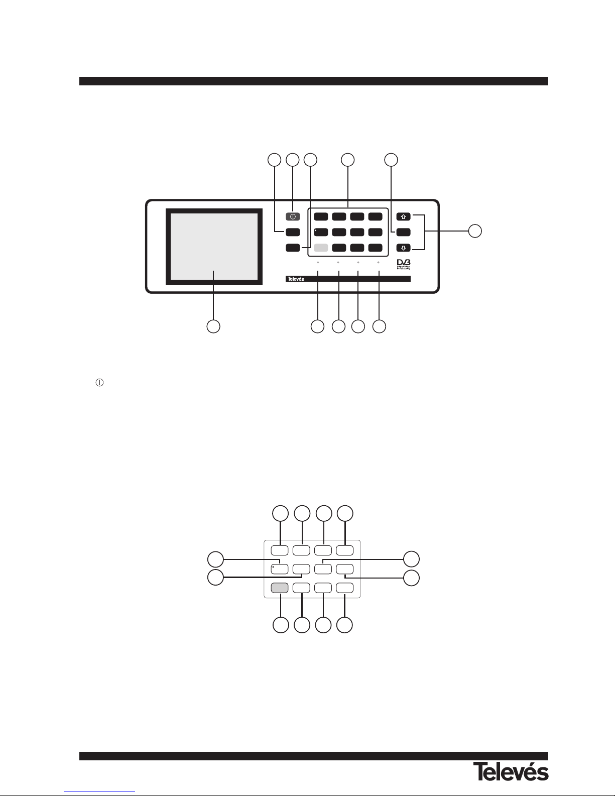
Figure 1.- Front panel.
[1]
On / Off key. This turns on the instrument, and the user can select either manual or automatic power-off.
[2] MONITOR.
Enables the measurement information displayed on-screen in TV mode (level measurement) to be selected.
[3] SCREEN.
Activation of VOLUME, CONTRAST, BRIGHTNESS, SATURATION (only ref. 4202) and HUE (this last only for NTSC colour system
and ref. 4202) control menus.
[4] MAIN KEYBOARD
12 keys to select functions and entering numeric data.
Figure 2.- Main keyboard.
[5] ENTER.
Validation of the different options.
In TV mode, press the ENTER [5] key to display a menu containing different functions, some are dependent on the band and the
standard:
Band switching Permits to change from terrestrial (5-862 MHz) to satellite band (920-2150 MHz) and vice versa.
A/D
0
SHIFT
CH/F
SPECT
1
7
LEVEL
2
FA
8
MODE
3
FB
9
SEARCH4MEMORY
5
LNB
6
SOUND
20
30
24
21 22 23
31 27 28 29
25
26
BATTERY OK CHARGER
EXT VIDEO
DRAIN
MONITOR
SCREEN
A/D
0
SHIFT
CH/F
SPECT
1
7
LEVEL
2
FA
8
MODE
3
FB
9
SEARCH4MEMORY
5
LNB
6
SOUND
Medidor de Campo Color TV&SAT MTD 120
ENTER
2
6
7
1 3 4 5
891011
112
TV & SAT Level Meter MTD 120 User Manual
Page 12

113
ENGLISH
TV & SAT Level Meter MTD 120 User Manual
System & Standard Selects the colour system (PAL, SECAM or NTSC) and the TV standard (B/G, D/K, I, L, M, N or Digital).
Battery & Lnb Displays battery voltage and external units power supply voltage and current (V Lnb and I Lnb).
Data logger Permits to acquire and to store up to 9801 measurements automatically.
Clock Displays time and date, and allows them to be modified.
Input Video Enables Scart commutation signals to be activated, deactivated or set to automatic/subordinate mode.
Channel set Selects active channels table.
Units Selects the measuring units: dBµV, dBmV or dBm.
Manual power Sets power-off as Manual or Automatic.
C/N setup Defines the C/N measuring method between Auto or Referenced.
Reference noise (Only in C/N Reference noise mode). Defines the frequency where measure the noise level.
Channel BW (Satellite band or digital channels). Defines channel bandwidth. Indispensable for measuring digital channels
and satellite band channel C/N.
Lnb local osc (Only satellite band). It defi nes the frequency of the local oscillator (L.O.) of the LNB.
Video polarity (Only satellite band, analogue channels). This selects the polarisation of the video carrier.
Nicam channel (Only analogue channels). This selects the NICAM sound channel that is sent to the loudspeaker.
Search level (Only analogue channels). Selects the threshold level of the automatic station search function.
Teletext (Only analogue channels). Sets teletext information.
DiSEqC (Only satellite channels). Defines a sequence of DiSEqC commands and permits to send them.
Beep Activates (ON) / deactivates (OFF) the beeper.
Equipment info. Displays information on the instrument: serial number, version of control software, options installed, etc.
Exit Exits from the function menu.
In Spectrum Analyser mode the menu displays the following functions:
Band switching Permits to switch from terrestrial (5-862 MHz) to satellite band (920-2150 MHz) and vice versa.
Span Defines the frequency range displayed between Full (the entire band), 500 MHz, 200 MHz, 100 MHz, 50
MHz, 32 MHz, 16 MHz and 8 MHz (the latter two only for terrestrial bands).
Reference level Defines the reference level between 70 and 130 dBµV in 10 dB steps.
Dual marker (Only analogue channels, level measurement mode and single marker mode). Enables dual markers to be
shown on the displayed spectrum.
Marker A (Only in dual marker mode). Selects marker A as the active marker (tuneable).
Marker B (Only in dual marker mode). Selects marker B as the active marker (tuneable).
Single marker (Only in dual marker mode). Activates the single marker on the displayed spectrum.
Sweep Selects sweep speed in spectrum mode between Fast (fast sweep, low accuracy) and High Resolution
(slow sweep, high accuracy).
Reference noise (Only in C/N measurements). Permits to define the frequency where noise level will be measured (see Carrier
function).
Channel bandwidth (Only in Channel Power measurements). Permits to define channel bandwidth (see Marker function).
Marker (Only when measuring Channel power and after defining the Channel bandwidth). Permits to change the
tuning frequency by means of the keys.
Carrier (Only when measuring C/N Referenced and after defining the Reference noise). Permits to change the tuning
frequency by means of the keys.
Measure bandwidth Selects the bandwidth of the spectrum measuring filter from among:
Terrestrial channels: 230 kHz or 1 MHz.
Satellite channels: 230 kHz or 4 MHz.
Channel set Selects active channels table.
Battery & Lnb Displays battery voltage and external units power supply voltage and current (V Lnb and I Lnb).
Exit Exits from the function menu.
Page 13

114
TV & SAT Level Meter MTD 120 User Manual
[6]
Tuning control and moving between the various on-screen menus.
Tuning purposes: when pressing key, frequency increases while when pressing key, frequency decreases.
To shift along the on-screen menus: when pressing key, active option moves upwards while when pressing key, active
option moves downwards.
[7] CHARGER.
External DC adapter operation indicator. When batteries are installed the battery charger is automatically activated.
[8] BATTERY OK.
Battery charge level indicator.
[9] DRAIN.
External units power supply indicator. Lights up when the MTD 120 supplies a current to the external unit.
[10] EXT VIDEO.
It lights up when an external video signal is present through the SCART connector [39].
[11] Monitor
[20] A/D
Switches between analogue and digital mode.
Key number 0 to enter numeric data.
[21] SPECT.
Enables switching between the TV and the Spectrum Analyser operation mode, and back again.
Key number 1 to enter numeric data.
[22] LEVEL.
Enables the type of measurement to be selected. The types of measurements available depend on the band, the standard, the
options included and the operating mode.
Key number 2 to enter numeric data.
[23] MODE
Selects the information displayed on-screen in TV operation mode (LV measurement).
Key number 3 to enter numeric data.
[24] SEARCH
This is the function for automatic station search. Starting at the present frequency or channel, it searches until finds a station with an
adequate level. The threshold level (search level) can be defined by means of the TV mode functions menu between 30 and 99
dBµV.
Key number 4 to enter numeric data.
[25] MEMORY
This key enables the measurement configuration to be stored/recalled. Each configuration has the following information: name
assigned to memory, memory number, Channel or frequency (Freq), TV system (TV Sys), measurement mode (Meas), external
units power supply (V Lnb), measurement units (Units) and Sound. The memory can store up to 99 measurement configurations
(numbered from 1 to 99).
Key number 5 to enter numeric data.
[26] SOUND
This selects the type of sound. The options available in each case depend on the band and the standard selected (see section 4.11
Selecting the Sound Mode).
Key number 6 to enter numeric data.
[27] LNB
Enables selecting the power supply to the external units. Available voltages are: External, 13 V, 15 V and 18 V for the terrestrial band
and External, 13 V, 15 V, 18 V, 13 V + 22 kHz, 15 V + 22 kHz and 18 V + 22 kHz for the satellite band.
Key number 7 to enter numeric data.
Page 14
115
ENGLISH
TV & SAT Level Meter MTD 120 User Manual
[28] FA
Direct access key which can be assigned to any function on any menu.
Key number 8 to enter numeric data.
[29] FB
Direct access key which can be assigned to any function on any menu.
Key number 9 to enter numeric data.
[30] CH/F
Switches tuning mode between channel and frequency. In channel mode the tuning frequency is defined by the active channels table
(CCIR, OIRT, ...). See channel-frequency tables in Appendix A.
Decimal point key to enter numeric data.
[31] SHIFT
Enables the desired frequency to be directly tuned using the numeric keyboard. Also acts as a SHIFT key for moving across different
fields on some screens.
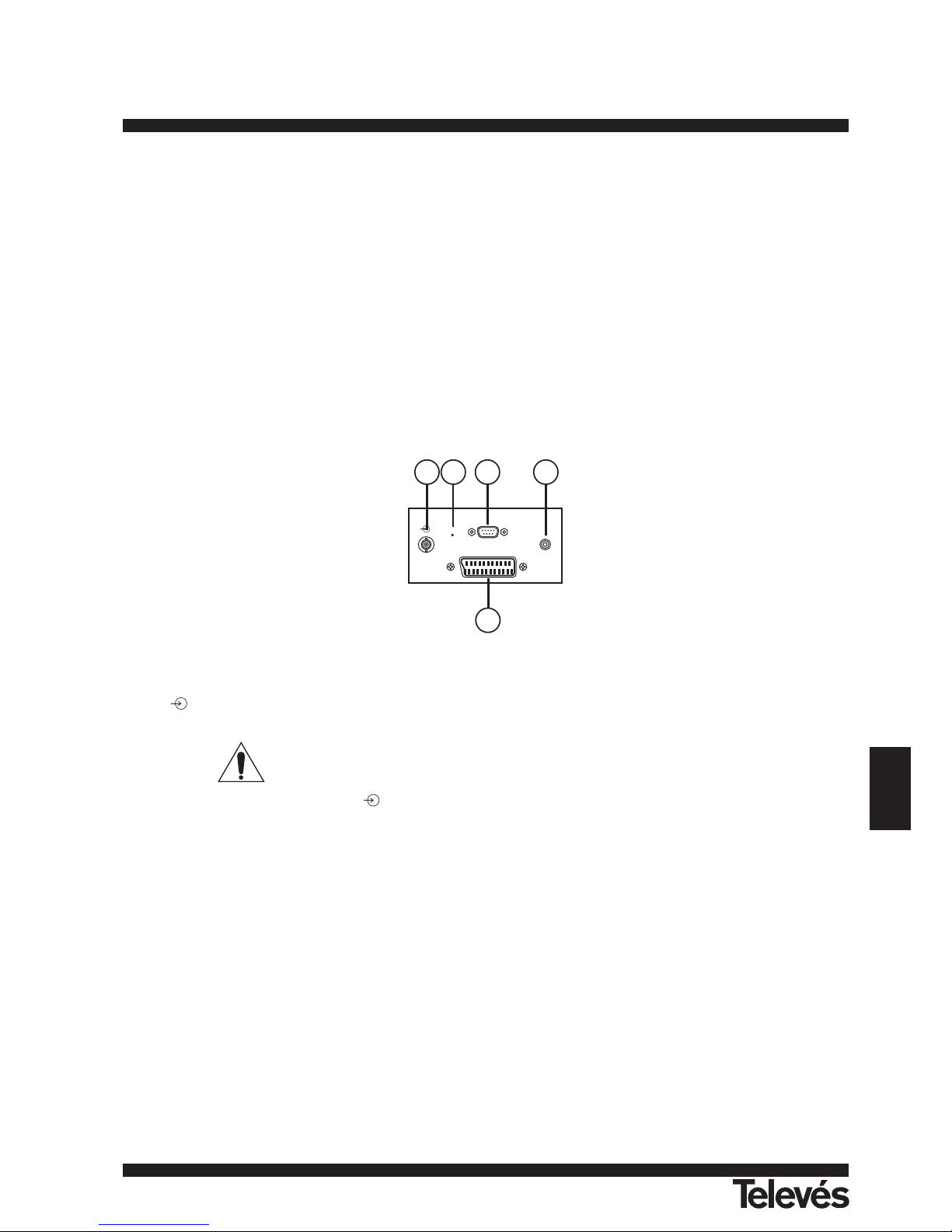
Figure 3.- Side panel connections.
[35] RF . RF signal input.
Maximum level 130 dBµV. Universal connector for F/F or F/BNC adapter, with input impedance of 75Ω.
ATTENTION
Note the importance to protect the RF [35] input signal with an accessory to block the AC voltages used in CATV cables
(needed to feed the amplifiers) and remote mode.
[36] RESET button
Enables the user to restart the instrument if there is any irregularity in its functioning. If it is necessary to reset the instrument, press
the reset button with the instrument turned off.
[37] Connector RS-232C
Enables the remote control of the MTD 120 from a personal computer, as well as data dumping to a printer.
[38] External 12 V power supply input
[39] Scart socket
RST
RS-232C
SCART ITF
EXT.
SUPPLY
39
383635 37
Page 15

116
TV & SAT Level Meter MTD 120 User Manual
4.2.- Adjustment of Volume and Monitor Parameters
Repeatedly pressing key SCREEN [3] sequentially activates the VOLUME, CONTRAST, BRIGHTNESS, SATURATION and HUE (this
last only for NTSC colour system) control menus. On activation of a menu for a specific parameter the screen displays a horizontal bar whose
length is proportional to the parameter level, to modify this value simply press keys [6]. To exit the menu and validate the new value
press key ENTER [5].
4.3.- Selecting the Operation Mode: TV / Spectrum Analyser
The MTD 120 has two basic operation modes: TV and Spectrum Analyser. To switch from one operation mode to the other press key
SPECT [21].
In the TV operation mode the demodulated television signal is shown on-screen; this is the default operation mode, various functions can
be selected, as shown in the following paragraphs.
In the Spectrum Analyser operation mode the screen displays the power spectrum of the active band (terrestrial or satellite). The span,
the reference level and the measuring filter bandwidth are variable as will be shown in paragraph '4.10 Spectrum Analyser Operation Mode'.
4.4.- RF Band Selection: 5-862 MHz / 920-2150 MHz
Tuning is continuous between 5 and 862 MHz (terrestrial band) and between 920 and 2150 MHz (satellite band). There are three ways of
changing the active band:
1. Press key ENTER [5] to accede to the functions menu, if necessary press keys [6] to select the Band switching function and
then press key ENTER [5] again. The RF band will be switched automatically.
2. Press key SHIFT [31] and select a frequency on the new band using the numeric keyboard. The fifth digit and second decimal act as
confirmation. For example, if the active band is the 920 to 2150 MHz band and you wish to tune the 49 MHz frequency (belonging to
the 5/45 to 862 MHz band), press key SHIFT [31] and then enter 49.00 or 0049.0 using the numeric keyboard.
3. Recall a memory with a tuning frequency belonging to the band you wish to access. (See section '4.12 Measurement Configuration
Memories').
4.5.- Channel Tuning / Frequency Tuning
Pressing key CH/F [30] the MTD 120 switches from frequency tuning to channel tuning and back again.
In channel tuning mode pressing keys [6] sequentially tunes the channels defi ned in the active channels table (see the Channel
set function in the TV mode functions menu, section '4.9.2.7 Selecting the Channels Table'). Pressing key frequency increases while
pressing key frequency decreases.
In frequency tuning mode there are two ways of tuning:
1. Pressing keys [6].
By means of keys [6] selects the desired frequency (tuning is continuous from 5 to 862 MHz and from 920 to 2150 MHz). When
pressing key frequency increases while pressing key frequency decreases.
2. Using the keyboard.
Press key SHIFT [31](the frequency listing will disappear), next enter the frequency value in MHz using the numeric keyboard, the fifth
digit and the second decimal act as confirmation. The MTD 120 will calculate the tuneable frequency closest to the entered value and
then display it on-screen.
4.6.- Búsqueda Automática de Emisoras
In the TV mode, by pressing the SEARCH [24] key search starts at the present frequency or channel until it fi nds a transmission with a
level higher than the search level. The threshold level is defined by means of the Search level function of the TV mode functions menu (see
paragraph '4.9.2.15 Search Level'.).
The Search function halts the search process when the end of the present band is reached, if it is in frequency mode, or when a key is
pressed. In channel mode, the search process is halted when the last channel of the group selected is reached (see Appendix A). The sound
is deactivated during the search process.
4.7.- Selecting Analogue / Digital Mode
Measuring the characteristics of a channel depends, in the first place, on the type of modulation: analogue or digital.
Use key A/D [20] to switch between analogue and digital channels. When switching to a new modulation, the MTD 120 activates the last
measurement configuration used for that modulation.
Page 16
117
ENGLISH
TV & SAT Level Meter MTD 120 User Manual
4.8.- External Units Power Supply (EXT. SUPPLY)
The MTD 120 can supply the voltage needed to power the external units (antenna preamplifiers, in the case of terrestrial TV, or LNB, in
the case of satellite TV).
Maximum input levels
DC to 100 Hz 50 V rms (powered by the power adapter)
30 V rms (not powered by the power adapter)
5 MHz to 2150 MHz 130 dBµV
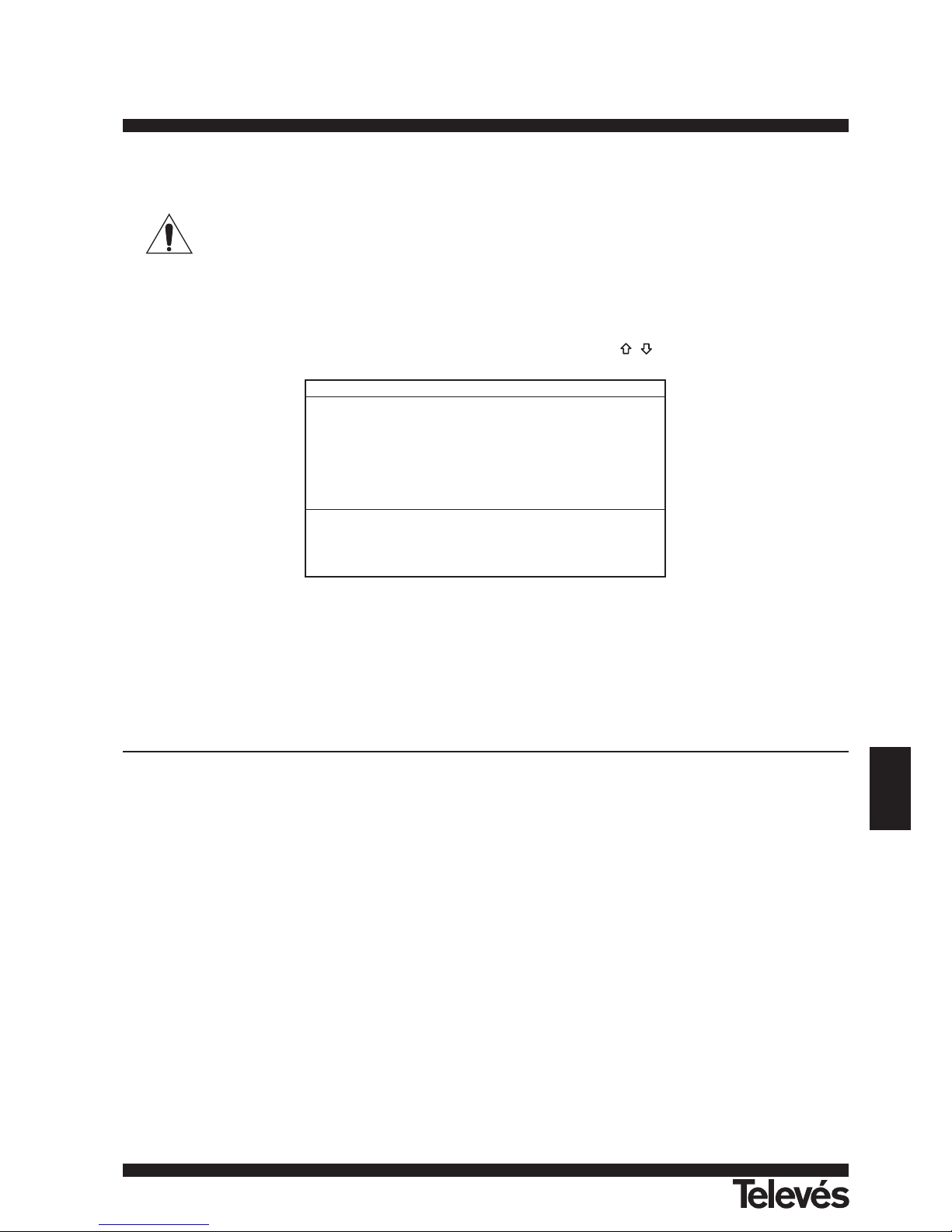
To select the supply voltage of the external units, press key LNB [27], and the screen will display a functions menu labelled EXT.
SUPPLY listing the choice of voltages (which will depend on the band being used). Use keys [6] to select the desired voltage and
press key ENTER [5] to activate it. The following table shows the choice of supply voltages:
Table 1.- External units powering voltages.
In the External power supply mode the unit powering the amplifiers before the antenna (terrestrial television) or the satellite TV receiver
(house-hold or community) also powers the external units.
The DRAIN [9] indicator lights when current is flowing to the external unit. If any kind of problem occurs (e.g., a short circuit), an error
message appears on the monitor ('SUPPLY SHORT'), the acoustic indicator will be heard and the instrument will cease to supply power. The
MTD 120 does not return to its normal operating state until the problem has been solved.
WARNING
When the external unit is powered with one of these voltages, particulary 18 V, it is not advisable for the instrument to function
for more than three minutes non-stop. Since the total consumption is very high, the duration of the battery charge is shortened
considerably. It is advisable to disconnect the instrument when it is not taking measurements.
Band Powering voltages
SATELLITE External
13 V
15 V
18 V
13 V + 22 kHz
15 V + 22 kHz
18 V + 22 kHz
TERRESTRIAL External
13 V
15 V
18 V
Page 17

118
TV & SAT Level Meter MTD 120 User Manual
4.9.- TV Operating Mode
4.9.1.- Selecting the Measurement Mode (MEASURE)
The types of measurements available depend on the band, the standard, the operating mode and the options included in the appliance.
Terrestrial band - Analogue channels:
Level Level measurement of the currently tuned carrier.
Video / Audio Video carrier to audio carrier ratio.
C / N Video carrier to noise ratio. There are two methods to make this measurement (selectable through the C/N setup
function):
Auto: In-channel measurement. Noise level is measured at a frequency where modulation contents is minimum. After
a small period of time, minimum measured level corresponds to noise level.
Referenced: The user defines the frequency where noise level will be measured (by means of the Reference noise
function). This frequency will be used to measure noise level for all channels.
Terrestrial band - Digital channels:
Channel power Automatic method: channel power is measured assuming that power spectral density is uniform throughout channel
bandwidth. To measure it correctly it is indispensable to define the Channel BW.
C/N Two methods selectable through the C/N setup function:
Auto: Out-channel measurement. Noise level is measured at f
noise
= f
tuning
- 1/2 Channel BW. To measure it correctly
digital channel must be tuned at its central frequency.
Referenced: The user defines the frequency where noise level will be measured (by means of the Reference noise
function). This frequency will be used to measure noise level for all channels.
Satellite band - Analogue channels:
Level Level measurement of the currently tuned carrier.
C/N Video carrier to noise ratio (Auto or Referenced, equivalent to terrestrial band, digital channels).
Satellite band - Digital channels
Channel power Automatic method.
C/N Channel level to noise ratio (Auto or Referenced, equivalent to terrestrial band, digital channels).
To change the measurement mode press key LEVEL [22]. The screen will display a menu with the measurement modes which can be
selected.
Figure 4.- Measuring mode selection (satellite band, analogue channels).
To select a measurement mode press keys [6] until it is marked (e.g., Level in the previous figure), then press key ENTER [5] or
key LEVEL [22] to activate the selected measurement mode.
MEASURE
Level
C/N (Referenced)
Exit
Page 18

119
ENGLISH
TV & SAT Level Meter MTD 120 User Manual
4.9.1.1.- Measuring the Video Carrier Level (Level)
If you select the Level measurement mode, the screen shows a window with the signal level, when selected with the key MONITOR [1]
(see next section).
WARNING
If a sudden signal level increase is produced at the RF input, and it is beyond the total signal levels of:
Terrestrial band: 95 dBµV
Satellite band: 105 dBµV
the tuning circuit may become out of control, giving as a result wrong level readings.
If this situation occurs, disconnect the input signal, change to Spectrum Analyser mode and select a Reference Level of 130
dBµV. Then connect the signal again and modify the Reference Level according to present signals.
Similar effects can be observed when at the RF input appears an important number of carriers with a high level. To be able to determinate
the equivalent level of a carrier group (with similar levels) at the RF input, it is possible to use the expression:
L
t
= L + 10 log N
L
t
: equivalent total level
L: average level of the carriers group
N: number of carriers
So, if there are ten carriers with a level around 90 dBµV, their equivalent level will be:
90 dBµV + 10 log 10 = 100 dBµV
Observe that in this case, loss of tuning by overload of the RF input may occur besides other effects such as tuner saturation and
generation of intermodulation products that may mask the spectrum visualization.
4.9.1.1.1.- On-screen Measurement Information
In TV operation mode, the measurement information to be displayed on-screen is selected by pressing key MONITOR [1]. Three
possibilities are offered, selected cyclically:
- TV image with a window in the lower part of the screen displaying the signal level and frequency/channel.
- TV image with a window displaying information on the name assigned to memory, power supply to external units, sound, colour system,
TV standard, level and frequency/channel.
- TV image only.
4.9.1.1.2.- Selecting TV Mode: TV, LV, SY (TV MODE)
In addition to operating as a television set, the monitor of the MTD 120 can act as an analogue level indicator, and can display the line
synchronising pulse just as it would appear on a screen of an oscilloscope.
To change the TV mode press key MODE [23], and the following screen will appear:
Figure 5.- TV mode selection.
Use keys [6] to choose the information you want to be displayed on-screen. Press key ENTER [5] or key MODE [23] to activate
the selected display mode.
TV MODE
TV
TV+LV
TV+LV+SYNC
LV
Exit
Page 19

The operation modes available are:
TV: Monitor operating as a conventional television set.
TV+LV: Monitor operating as a conventional television set, with a level indicator on the upper part of the screen (the
analogue bar).
TV+LV+SY: Monitor operating as a conventional television set, with a level indicator and the line synchronizing pulse
displayed on the screen.
LV: Signal level indicationon the upper part of the screen (analogue bar).
Operation in TV+LV+SY Mode
This function permits to display the line synchronising pulse corresponding to a tuned signal on the monitor.
To view the synchronisation pulse press key MODE [23], use keys [6] to select TV + LV + SY mode, and then press key MODE
[23] or key ENTER [5].
The monitor is divided into three sections. In the top section an analogue bar appears which indicates the level of the signal received (79
dBµV in figure 6 example). On the left side the line synchronising pulse is represented as it would appear on the screen of an oscilloscope.
On the lower side the TV picture is shown.
Figure 6.- Line synchronism + level + TV (TV+LV+SY).
Starting from the line synchronism representation, it is possible to perform a qualitative analysis of the TV picture delivered to the end
user.
4.9.1.2.- Measuring the Video / Audio Ratio (V/A)
In the Video/Audio measurement mode, the screen displays the following information:
Figure 7.- Video/Audio rate measurement.
In addition to the video carrier / audio carrier ratio (15.0 dB in previous figure) this also shows the frequency or channel, depending on the
tuning mode selected, and the level of the video carrier and audio carrier.
VIDEO/AUDIO
15.0 dB
VIDEO CARRIER:
Frequency = 519.25 MHz
Level = 60.2 dBuV
AUDIO CARRIER:
Frequency = 5.50 MHz
Level = 45.2 dBuV
60 70 80 90 100
120
TV & SAT Level Meter MTD 120 User Manual
Page 20

121
ENGLISH
TV & SAT Level Meter MTD 120 User Manual
4.9.1.3.- Measuring the Carrier / Noise Ratio (C/N)
The MTD 120 offers two ways to make this measurement:
Auto: The MTD 120 defines the frequency where noise level is measured automatically.
Reference noise: The user defines the frequency where noise level is measured (by means of the Reference noise function). This frequency
will be used to measure noise level for all channels.
To select the measuring method activate the TV mode functions menu by pressing key ENTER [5], then use keys [6] to select C/N
setup function and finally press key ENTER [5] again. The monitor will show a screen displaying two possibilities: C/N (Auto) and C/N (Reference
noise), then use keys [6]to select the desired option and finally press key ENTER [5] to confirm.
When selecting the C/N (Reference noise) mode it is necessary to define the noise frequency: access the functions menu and now use keys
[6] to select Reference noise function and finally press ENTER [5] again. A screen titled REFERENCE NOISE will be displayed showing
the noise frequency in use. To change it press key SHIFT [31], the current frequency value will disappear and, using the keyboard, you will be able to
enter the new reference noise frequency in MHz and with two decimals figures. This frequency also can be modified in the Spectrum operation mode
(see 4.10.2.2. C/N (Referenced Measurement).
The MTD 120 carries out C/N ratio measurement in four different ways, according to the carrier type and the band in use:
A) Terrestrial band, analogue carrier
Carrier level is measured using a quasi-peak detector (230 kHz BW). Noise level is measured with an average detector and corrected to refer
it to channel bandwidth (according to the standard in use).
B) Terrestrial band, digital carrier
Both measurements are done with an average detector (230 kHz) and the same corrections are introduced on them (bandwidth corrections).
C) Satellite band, analogue carrier
Carrier level is measured using a quasi-peak detector (4 MHz BW). Noise level is measured with an average detector (4 MHz) and corrected
to refer it to channel bandwidth.
D) Satellite band, digital carrier
Equivalent to case B but now using the 4 MHz BW filter.
On selecting the Carrier / Noise measurement mode the screen displays the following information:
Figure 8.- Carrier-to-noise ratio measurement (Satellite band, analogue signal).
As well as the video carrier / noise level ratio (20.1 dB in previous figure), the frequency or channel (depending on the tuning mode
selected) and the level of the video carrier and noise level are also shown.
When measuring channels in the satellite band or digital channels, to measure the C/N ratio correctly, the bandwidth of the channel must be
defined previously, using the Channel BW function on the TV mode functions menu.
IMPORTANT REMARK
To measure digital channels C/N ratio in Auto mode it is indispensable to tune channel at its central frequency.
IMPORTANT REMARK
In the case of an analogue terrestrial signal, when C/N (Auto) mode is selected, the MTD 120 performs an in-channel
measurement, this involves that C/N value will take several seconds to stabilize (six seconds at the most). An arrow below the C/N
readout represents the measurement cycle and it is necessary to wait the arrow passes twice on the same point to guarantee a
correct measurement.
C/N (Auto)
20.1 dB
VIDEO CARRIER:
Frequency = 1345.5 MHz
Level = 64.1 dBuV
NOISE:
Frequency = 1329.5 MHz
Power = 44.1 dBuV
Channel BW = 32.0 MHz
Page 21
122
TV & SAT Level Meter MTD 120 User Manual
4.9.1.4.- Measuring the Power of Digital Channels (Channel power)
The MTD 120 offers two different methods to measure digital channels power, according to the active operation mode: Automatic method
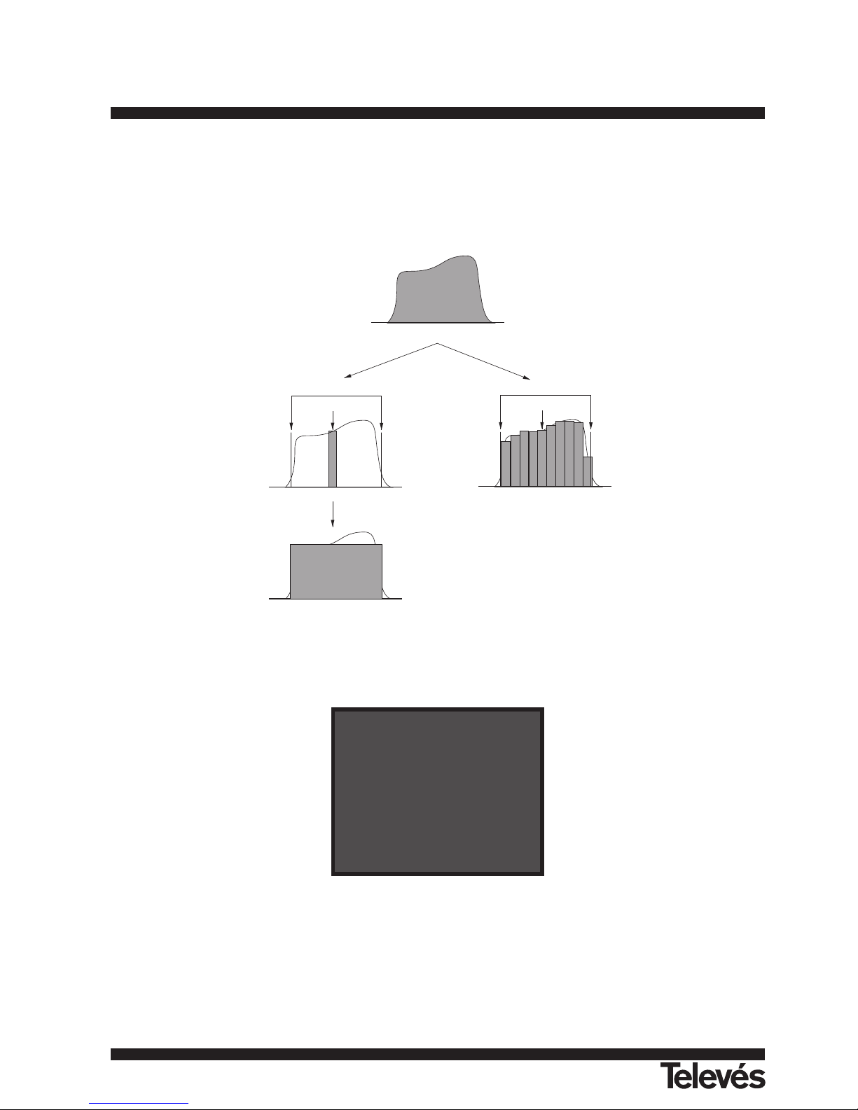
in TV mode and Integration method in Spectrum mode. The Automatic method measures digital channel power in the measurement filter
bandwidth and estimates total channel power assuming that spectral density is uniform throughout channel bandwidth. On the other hand, the
Integration method takes into account signal spectral distribution so measurement is more accurate (see 4.10.2 Selecting the
Measurements Mode). The obtained readouts using these methods may differ some dBs, specially when the digital signal is degraded.
Figure 9.- Measuring digital power.
On selecting the CHANNEL POWER measurement mode, the screen displays the following information:
Figure 10.- Digital channel power measurement.
In addition to the power of the digital channel (45.8 dBµV in previous figure) this also shows the tuning frequency or channel, depending
on the tuning mode selected, and the parameters regarding bandwidth: Channel BW and measuring filter bandwidth (Measure BW).
For the power measurement of a digital channel to be correct it is essential to have previously defined the channel bandwidth using the
Channel BW function, in the TV mode functions menu (see section '4.9.2.11 Channel Bandwidth’).
CHANNEL POWER
45.8 dBuV
DIGITAL CARRIER:
Frequency = 538.00 MHz
BANDWIDTH PARAMETERS:
Channel BW = 8.00 MHz
Measure BW = 230 KHz
TV mode
Channel BW
Marker
Spectrum
Channel BW
Marker
Power measurement by integration method
Digital channel power
Mesure BW
Power measurement by the automatic method
Page 22
123
ENGLISH
TV & SAT Level Meter MTD 120 User Manual
4.9.2.- TV Mode Functions Menu
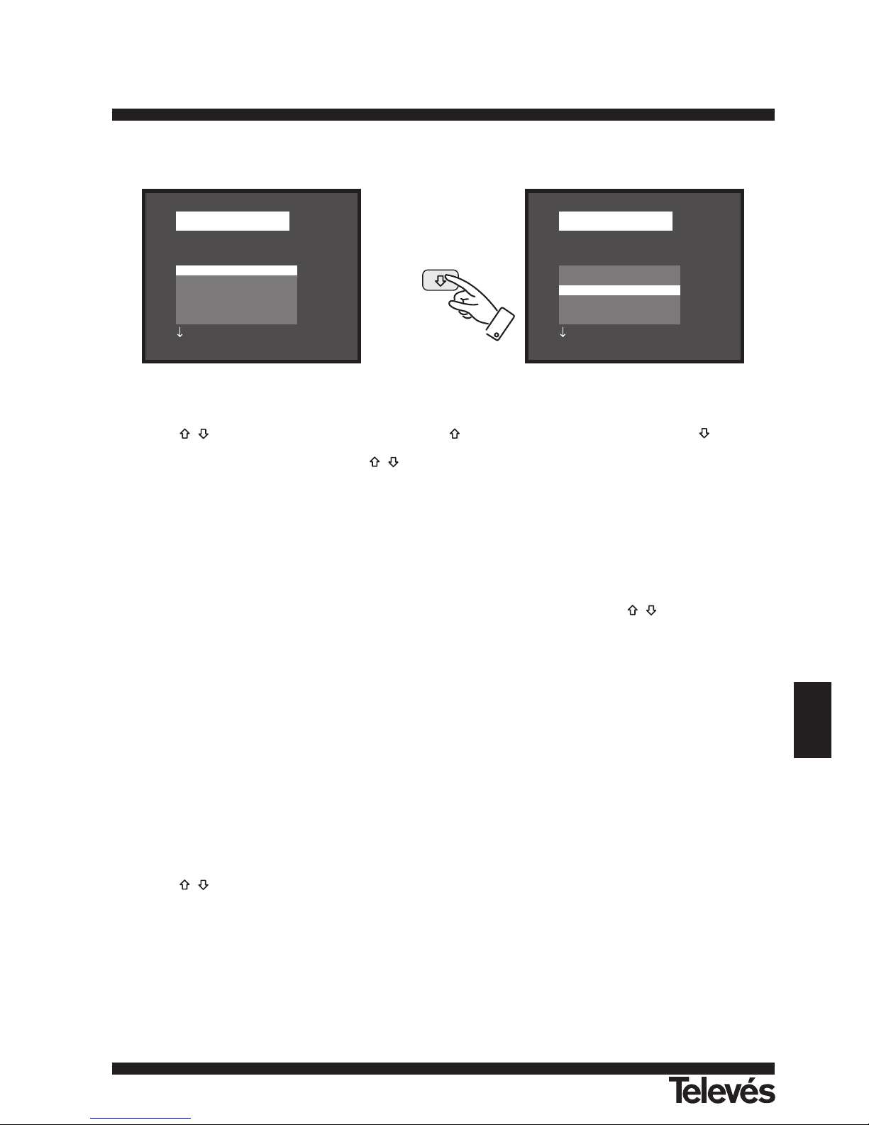
In TV operation mode, press key ENTER [5] to access the functions menu of the TV mode:
Figure 11.- TV mode functions menu.
Use keys [6] to choose the different functions: pressing key active option moves upwards while pressing key active option
moves downwards. The downwards or upwards facing arrow at the bottom or top-left hand side of the functions menu indicates there are
more menus which can be accessed by pressing keys [6].
Below we describe the use of each function and its range of values.
4.9.2.1.- Selection of the RF Band: (Band switching)
Permits to switch from terrestrial (5-862 MHz) to satellite band (920-2150 MHz) and vice versa.
4.9.2.2.- Selection of the TV System and Standard (System & Standard)
This function enables the television system and standard to be changed. The standards which can be selected depend on the band in use
(terrestrial or satellite channels). To change the standard access the TV mode functions menu, then use keys [6] to select the System
& Standard function and press key ENTER [5]. A fold down menu will appear listing the following options:
Terrestrial bands Satellite band
PAL-B/G PAL
PAL-D/K SECAM
PAL-I NTSC
PAL-M Digital
PAL-N
SECAM-B/G
SECAM-L
SECAM-D/K
NTSC-M
Digital
Use keys [6] to select the desired standard and press key ENTER [5] to activate it.
If a digital channel is selected, whether terrestrial or satellite, for the measurement of the level and the carrier-to-noise ratio to be correct,
the bandwidth of the channel must be defined, using the Channel BW function of the functions menu.
The following table shows the features of the analogue terrestrial channel standards.
FUNCTIONS
Band switching
System & Standard
Battery & Lnb
Data logger
Clock
Input video
FUNCTIONS
Band switching
System & Standard
Battery & Lnb
Data logger
Clock
Input video
Page 23
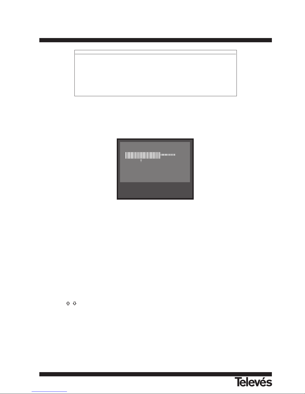
Table 2.- Selectable terrestrial analogue standards and their characteristics.
4.9.2.3.- Batteries and External Units Power Supply (Battery & Lnb)
This function allows you to check the charge state of the batteries, as well as the supply current and voltage of the external units. From
the TV operation mode, simply press key ENTER [5] select the Battery & Lnb function and press key ENTER [5]again. You will see a screen
like the following one:
Figure 12.- Battery&Lnb function.
The top part of the screen displays the battery voltage (6,1 V in previous figure), both numerically and with a bar graph. The arrow
labelled L Bat below the horizontal bar signals the low battery level where the battery should be charged. When batteries are fully charged,
battery voltage indication is 6.1 V or higher.
The bottom of the screen shows the voltage supplied to the external units (V LNB, 12.6 V in the figure above) and the current supplied
(I LNB, 200.0 mA in the example).
To leave this function press key ENTER [5].
4.9.2.4.- Data Logger Function
The Data logger function allows the user to carry out, store and/or print out up to 9801 measurements in a fully automatic way. It may be
understood as a measurement matrix whose columns address the 99 measuring configurations (defined in the 99 memories of the
equipment) and whose lines permit to store 99 measurements for every measuring configuration (conducted in different points of the system
or in the same point on different times).
Before to proceed to take measurements by means of the Data logger function it is necessary to store the measuring configuration/s in
the memory by using the Store function (see paragraph 4.12.1).
To select the Data logger function activate the TV mode functions menu, by pressing key ENTER [5] when in the TV operation mode.
Then, use keys [6] to select the Data logger field and press key ENTER [5], the DATALOGGER screen will appear automatically.
BA TTER Y : 6.1 V
V LNB : 12.6 V
I LNB : 200 mA
L Bat
System Lines/frame Channel Bandwidth Video/sound separation Video mode Audio mode
B 625/50 7 MHz 5,5 MHz Neg FM
D 625/50 8 6,5 Neg FM
G 625/50 8 5,5 Neg FM
H 625/50 8 5,5 Neg FM
I 625/50 8 6,0 Neg FM
K 625/50 8 6,5 Neg FM
L 625/50 8 6,5 Pos AM
M 525/60 6 4,5 Neg FM
N 625/50 6 4,5 Neg FM
124
TV & SAT Level Meter MTD 120 User Manual
Page 24

125
ENGLISH
TV & SAT Level Meter MTD 120 User Manual
Figure 13.- DATALOGGER screen.
As you can see in the previous figure, the main screen of the Data logger function has three functions: Config (Configuration), Run and
Exit. Below these three functions is the measurements matrix, three columns and five rows are simultaneously displayed (in the previous
figure the data logger has three stored measurements, one for each of the first three memories).
To access the various screen functions or fields press key SHIFT [31] repeatedly.
4.9.2.4.1.- Configuring the Data Logger Function
The configuration menu of the Data logger function allows you to choose between taking and/or printing measurements, programming
the MTD 120 to take measurements at a pre-determined time, defining the time interval between measurements, erasing all measurements
stored in the Data logger function, and automatically deactivating all the measurement configurations.
To define the configuration of the Data logger function press key SHIFT [31] repeatedly until you have selected the Config field and then
press key ENTER [5]. The configuration screen of the Data logger function will then appear.
Figure 14.- Configuration of the DATA LOGGER function
After an interval of half a minute without the MTD 120 controls being touched, it will automatically return to the Data logger function main
screen.
1.- TO MEASURE, PRINT OR MEASURE AND PRINT?
First of all, the user must indicate whether he wants to take measurements or to print them, or to do both at the same time. To do this,
press key SHIFT [31] repeatedly until positioned in the Measure field. Then use keys [6] to activate (On) or deactivate (Off) the
measurement function and press key SHIFT [31]. The next step is to activate or deactivate the measurement printing function. To do this, use
the key SHIFT [31] to position the cursor in the Print field and activate it (On) or deactivate it ( Off) using keys [6] and pressing key
ENTER [5] validate the new state.
2.- PROGRAMMING THE ALARM
To program the instrument to take measurements and/or print-outs at a specific time, you must define the time and date the
measurements are to be taken (Start acquisition time). If this field is not defined the acquisition of measurements will have to be activated
manually (see section '4.9.2.4.3 Taking Measurements'). When programming the alarm be sure to have checked that the date and time have
been correctly defined beforehand (Clock function, paragraph 4.9.2.5) and to have selected previously one measurement to be taken at
minimum (see section '4.9.2.4.2 Selecting the Measurements to be Taken').
To define the starting time of measurement acquisition repeatedly press key SHIFT [31] until the Start acquisition time field blinks, then
DATALOGGER
Measure: On Print: Off
Start acquisition time:
.. : .. : .., .. / ..
Measure interval: 00 : 15
Clear Unselect
DATALOGGER
•> Config • Run • Exit
1 2 3
1 49.8 55.2 53.4
2 ... ... ...
3 ... ... ...
4 ... ... ...
5 ... ... ...
Page 25

press key ENTER [5]. This will lead to a screen like the one shown below:
Figure 15.- Defining the starting time of measurement acquisition.
The first line of this screen tells you if the alarm function is on (ALARM On) or not (ALARM Off), followed by the date and time the alarm
has been set for, and the last line shows the current time and date.
Repeatedly pressing key SHIFT [31] cyclically activates the different fields in the following order: Hour, Minute, Second, Day, Month and
Alarm (alarm state). To alter any of these simply activate it, using keys [6] and press key SHIFT [31] again. Once you have updated
all the alarm fields, press key ENTER [5] to validate them and exit the screen.
If before activating the alarm (ALARM On) no measurement matrix cell has yet been activated (see section '4.9.2.4.2 Selecting the
Measurements to be Taken'), the bottom of the screen will show the error message "NOT CELLS SEL." (No cells have been selected)
followed by "DL STOPPED" (Data Logger deactivated).
On reaching the time defined in the Start acquisition time field, the instrument will switch itself on (if it was switched off) or go to the
Data logger mode (if switched on) to automatically take the measurements and/or produce the print-out.
3.- MULTIPLE MEASUREMENTS: INTERVAL BETWEEN MEASUREMENTS
In the case of having to take multiple measurements at different times the Measure interval will have to be defined. This field specifies
the time interval between measurements/print-outs. To define it, from the Data logger configuration screen, repeatedly press key SHIFT [31]
until the section dealing with time in the Measure interval field has been activated, define the hours by using keys [6], then press key
SHIFT [31] again to go to the minutes field and define these in the same way. Finally press key SHIFT [31] again to validate the defined time
interval.
You can make as many acquisitions as there are activated rows in the measurement matrix (if only one row has been activated, then only
one measurement will be taken).
In the case where the Data logger function has been programmed to take more than one measurement in the time domain, i.e. more than
one row has been activated and the acquisition interval is greater than four minutes, then every time an acquisition is made the instrument will
reprogram the alarm for the next measurement. Then it will switch itself on three minutes before the time defined in the Measure Interval field
in order to warm up and ensure the highest accuracy.
4.- ERASING MEASUREMENTS STORED IN THE DATA LOGGER AND AUTOMATIC DEACTIVATION OF ALL THE CELLS.
The configuration screen also allows you to erase all the measurements stored in the Data Logger function, as well as automatically
deactivating all the activated measurement configurations. To erase the stored measurements select the Clear field and press key ENTER
[5]. To deactivate the measurement configurations select the Unselect field and press key ENTER [5].
5.- EXITING THE CONFIGURATION SCREEN
To exit the Data logger function configuration screen press key ENTER [5].
ALARM Off
Hour : 07 Day : 01
Minute : 00 Month : 05
Second : 00
Time 12:03:16 30/04/1999
126
TV & SAT Level Meter MTD 120 User Manual
Page 26

127
ENGLISH
TV & SAT Level Meter MTD 120 User Manual
4.9.2.4.2.- Selecting the Measurements to be Taken
Once the Data logger function has been configured, activate the measurement configuration(s) (columns) which you would like to use.
The headings of the measurement matrix columns of the Data logger function coincide with the number of memorised measurement
configurations, simply place the cursor over each column and you will see the more important parameters displayed at the bottom of the
screen (name assigned to the memory position, frequency/channel, measurement mode and units of measurement).
To activate the measurement configurations repeatedly press key SHIFT [31] until the cursor is placed on the columns field, next
pressing keys [6] until it is positioned in the column (memory) that you wish to activate and press key ENTER [5]. The activated
columns are more brilliant than the non activated ones. To deactivate a column follow the same steps as in activating it.
To activate rows where you wish to store measurements use key SHIFT [31] to place the cursor on the rows field, then press keys
[6] until it is over the row you want to activate and press key ENTER [5]. The activated rows are more brilliant than the non activated
ones. To deactivate a row follow the same steps as in activating it. In the case of activating more than one row, the time interval between the
measurement of each row is determined by the Measure interval parameter defined in the configuration screen (1 minute by default).
4.9.2.4.3.- Taking Measurements
In addition to execution by alarm (see section '4.9.2.4.1 Configuring the Data Logger Function') there are three more ways to take
measurements:
a) Acquisition over a time period.
The measurement defined in a memory (column) will be taken as many times as there are activated rows, as specified by the time
interval between measurements defined in the configuration menu (Measure interval).
Process: place the cursor on the column you want and press key ENTER [5] until the first active cell blinks. If no measurement matrix
row has been previously activated, the bottom of the screen will show the error message "NOT CELLS SEL." (No cells selected).
b) Acquisition of different measurements at the same moment.
Multiple measurements in a row will be taken, as specifi ed by the measurement configurations defined in all the activated columns.
Process: place the cursor on the row you want and press key ENTER [5] until the active cells blink. If no measurement matrix column
has been previously activated, the bottom of the screen will show the error message "NOT CELLS SEL.".
c) Multiple acquisitions.
All the measurements defined by all the activated rows and columns will be taken, in the case where more than one row has been
activated the time interval between measurements will be that defined in the Measure interval field of the configuration menu.
Process: select the Run function and press key ENTER [5]. If no measurement matrix element has been previously activated, the
bottom of the screen will show the message "NOT CELLS SEL.".
If any key is pressed during the acquisition process, the acquisition process will abort and the screen will display the message "DL
STOPPED" (Data Logger deactivated).
4.9.2.4.4.- Exiting the Data Logger Function
To exit the Data logger function select the Exit field using key SHIFT [31] then press key ENTER [5].
4.9.2.4.5.- Examples of Data Logger Function Applications
The Data logger function has many applications such as channel equalisation and measuring signal attenuation at each pickup.
Band Equalisation (frequency acquisition)
For this application you will need to use a noise generator as the signal source in the place of a receiver antenna. If, lets say, you wish to
verify equalisation on the VHF band, then:
1. Define the following tuning frequencies at 8 memory positions: from 50 to 450 MHz in 50 MHz steps. The measurement to be taken will
be the level measurement.
2. In the Data logger function, activate the columns related to the memories defined in the previous step.
3. Next place the cursor on the row where you want to store the measurements and press key ENTER [5] until the first of the cells blinks.
The measurements obtained will allow you to verify if the signal level is uniform across the entire band.
Page 27

Measuring signal level fluctuation at a pickup (acquisition over a time period)
1. Define the acquisition time interval Measure interval (1 h for example).
2. Activate a column (a measurement configuration you consider significant).
3. Activate the necessary number of rows to be able to perform the study over the decided upon period of time, taking into account the
previously defined acquisition interval (e.g. for a 24 hour study with an acquisition interval of 1 h you will need to activate 24 rows).
4. Finally place the cursor on the activated column and press key ENTER [5] until the first active cell blinks.
The report obtained will allow you to guarantee the correct operation of the installation.
4.9.2.5.- Clock
An internal clock permits to record date and hour of data acquisitions.
To modify the time/date access the TV mode functions menu, press keys [6] to select the Clock function and press key ENTER
[5] to activate it. The monitor will show a screen labelled CLOCK displaying the hour, minute, second, day, month and year.
To alter any parameter repeatedly press key SHIFT [31] until the parameter you want to modify appears shadowed, then press keys
[6]. If you want to alter more parameters repeatedly press key SHIFT [31] again. To validate the changes made and exit press key
ENTER [5].
4.9.2.6.- Input Video
The Input video function enables Scart connector signals to be controlled. There are three possibilities:
Scart Auto Normal Scart operation
Scart On External video operation mode
Scart Off Scart deactivated
To select the Scart operation mode, access the TV mode functions menu, press keys [6] to the Input video function and press
key ENTER [5] to activate it. The monitor will show a screen labelled INPUT VIDEO displaying the three available options (as well as the Exit
option). Press keys [6] to select the mode you require, then press key ENTER [5] to activate it.
4.9.2.7.- Selecting the Channels Table (Channel set)
The MTD 120 comes with twelve stored channel tables as standard (four for terrestrial television and eight for satellite), for greater
adaptability to the selection requirements of different countries or zones. See the channel-frequency table in appendix A of the manual.
To modify one channel table, access the TV mode functions menu, press keys [6] to select the Channel set function and press
key ENTER [5] to activate it. The monitor will then show the CHANNEL SET screen. Press keys [6] to select the desired table and
then presss key ENTER [5] again to activate it.
4.9.2.8.- Measurement Units
The MTD 120 offers three measurement units to measure level and channel power: dBµV, dBmV and dBm.
To select the units of measurement, access the TV mode functions menu, press keys [6] to select the Units function and press
key ENTER [5] to activate it. The monitor will show a screen labelled UNITS displaying the three available options (as well as the Exit option).
Press keys [6] to select the units you require, then press key ENTER [5] to activate it.
4.9.2.9.- Power Off Mode (Manual power)
The MTD 120 offers two power-off modes: Manual and Automatic (unit disconnects automatically after 15 minutes without operating on
any control).
To select the power-off mode, access the TV mode functions menu, press keys [6] to select the Manual power function and press
key ENTER [5] to activate it. The monitor will show a screen labelled POWER OFF displaying the two available options (as well as the Exit
option). Press keys [6] to select the power-off mode you require, then press key ENTER [5] to activate it.
128
TV & SAT Level Meter MTD 120 User Manual
Page 28

129
ENGLISH
TV & SAT Level Meter MTD 120 User Manual
4.9.2.10.- C/N setup
To measure C/N the MTD 120 offers two different modes in TV mode:
C/N (Auto) The MTD 120 defines automatically the frequency where noise level is measured, according with:
f
noise
= f
tuning
- 1/2 Channel BW
C/N (Reference noise) The user defines the frequency where noise level is measured (by means of the Reference noise
function). This frequency will be used to measure noise level for all channels.
To select C/N mode, access the TV mode functions menu, press keys [6] to select the C/N setup function and press key ENTER
[5] to activate it. The monitor will show a screen labelled C/N SETUP displaying the two available options (as well as the Exit option). Press
keys [6] to select the mode you require, then press key ENTER [5] to activate it.
4.9.2.11.- Channel Bandwidth (Channel BW)
To measure the power and C/N ratio of digital channels, as well as the C/N ratio of satellite band channels, you first need to define the
channel bandwidth.
To modify the bandwidth access the TV mode functions menu and select the Channel BW function, press key ENTER [5] to activate it.
The CHANNEL BANDWIDTH screen will be displayed. To alter the bandwidth value press key SHIFT [31], the bandwidth will disappear and,
using the keyboard, you will be able to enter the new digital channel bandwidth in MHz and with two decimals.
4.9.2.12.- LNB Local Oscillator Frequency (Lnb local osc)
This option only affects reception of satellite band signals when using the channel tuning mode. This function defines the LNB local
oscillator frequency used in the installation where the MTD 120 has been connected. Given that the MTD 120 satellite channel tables have
been defined in the Ku band and the MTD 120 tunes in IF (like all satellite receivers) the LNB local oscillator frequency has to be defined to
correctly tune the channel mode.
To modify this parameter access the TV mode functions menu (satellite band), press keys [6] to select the Lnb local osc function
and press key ENTER [5] to activate it. The monitor will show a screen labelled LNB LOCAL OSCILLATOR displaying the current value of
the LNB local oscillator frequency. To alter this value press key SHIFT [31], the current value will disappear and the new value can now be
entered using the keyboard.
The frequency of the LNB local oscillator is expressed in MHz, with 5 figures for the whole part, a decimal point and a decimal figure
(which acts as confirmation). For example, to select 9 GHz the number 9000.0 has to be entered. Values must be defi ned between 8000.0
and 12000.0.
4.9.2.13.- Video Polarity
This option affects reception of SAT (satellite) band signals. It allows selection of either negative and positive video polarity.
To modify the polarity access the TV mode functions menu (satellite band), select the Video Polarity function, and press key ENTER [5]
to activate it. The monitor will show a screen labelled POLARITY displaying two possibilities: Positive Video and Negative Video. Pressing
keys [6] mark the option you require and finally press key ENTER [5] to activate it.
4.9.2.14.- NICAM Channel
Use this function to verify NICAM sound modulations in stereo and dual, you can also select the sound channel coming over the speaker.
To change the decoded channel access the TV mode functions menu, select the Nicam channel function, and press key ENTER [5] to
activate it. The monitor will show a screen labelled NICAM offering two possibilities: Channel A and Channel B. Press keys [6] to
select the desired option and finally press key ENTER [5] to activate it.
4.9.2.15.- Search Level
Use this function to modify the threshold level of the automatic station search. To change the level place the cursor on the Search level
field and press key ENTER [5]. The monitor will display a window showing the current value of the search level, to alter it press key SHIFT
[31] and enter the new value on the keyboard. Confirmation is automatic on entering the second digit.
4.9.2.16.- Teletext
When the Teletext function is selected, Teletext information appears on the monitor if a transmitter with this information is tuned. The first
page to appear on the screen is always page 100. If Teletext data is received, a counter located on the upper edge of the screen indicates the
page that is being processed. To change active page press key SHIFT [31], and introduce the new number using the numeric keyboard (third
digit acts as confirmation).
If the page requested is not included in the Teletext service of the transmitter, the search will continue indefinitely. In such a situation the
user can halt the search process, either by entering a new page number or by exiting the Teletext function pushing any control relative to
another function.
Page 29

130
TV & SAT Level Meter MTD 120 User Manual
The Teletext function is especially valuable for the final optimization process in TV installations. Any interference or reception through
indirect beams generates digital in the digital information of the Teletext, which are highly visible as erroneous characters on the screen.
4.9.2.17.- DiSEqC (*) Command Generator
DiSEqC ('Digital Satellite Equipment Control') is a communication protocol between the satellite receiver and the accessories of the
installation (switches, LNBs, etc.) proposed by Eutelsat, with the aim to standardize the diversity of switching protocols (13 - 15 - 18 V, 22
kHz, 60-400 Hz) and to satisfy the demands of the digital TV installations.
To define and/or to send a DiSEqC commands sequence, from the TV operation mode, press key ENTER [5], select the DiSEqC function
using keys [6] and press key ENTER [5] again. A screen like next one will appear:
Figure 16.- DiSEqC commands screen.
DiSEqC screen is divided in 3 areas: the field to edit the DiSEqC commands sequence (only command Sat A/B in previous figure),
Send/Clear functions and Exit.
To define the DiSEqC commands sequence press key SHIFT [31] repeatedly until cursor is positioned on one line of the commands
sequence (the line will blink). If cursor has been placed on the first empty line, Sat A/B command will appear (first DiSEqC command of table
3). To select a different command press keys [6] until the desired command appears and then press key ENTER [5].
Some DiSEqC commands need to define an associated parameter (i.e. On/Off, a numerical value, A/B...), when any of these commands
is selected first option for the associated parameter appears automatically at its right, to change it press keys [6] and to validate it
press key ENTER [5] (see DiSEqC commands table).
Once the DiSEqC command is defined, the cursor will pass to the following line, if you want to define a new command proceed as for the
first one, if you do not want to add any command press key SHIFT [31].
After the commands sequence is created it is possible to modify it. To modify the sequence press key SHIFT [31] repeatedly until you
have positioned the cursor on the command you want to make the change and then press key ENTER [5]: Insert function will appear on the
screen, by pressing keys [6] it is possible to select Delete and Edit functions. Once the desired function appears on the screen
(Insert, Delete or Edit) press ENTER [5].If you select Delete function the command will be removed from the sequence, if you select Insert or
Edit functions, you must define the new command as previously described.
Once commands sequence is defined, to send it to the peripherals press key SHIFT [31] repeatedly until you have selected the Send
function and then press key ENTER [5]. At the same time as DiSEqC commands are sent these appear on the lower side of the monitor. If
Send function does not appear on the monitor, place the cursor over the Clear function and press keys [6].
It is possible to delete the whole of the commands sequence, to do this press key SHIFT [31] repeatedly until you have selected the Clear
field and then press key ENTER [5]. If Clear function does not appear on the monitor, place the cursor over the Send function and press keys
[6].
To exit DiSEqC function place the cursor over the Exit field and then press key ENTER [5].
REMARK: When disconnecting the unit, the commands sequence will NOT be lost.
Next table shows the DiSEqC commands available:
DiSEqC 1.2
Sat A/B A
.......................... ....
.......................... ....
.......................... ....
.......................... ....
.......................... ....
Page: 1/1 Send Exit
(*)
DiSEqC™ is a trademark of EUTELSAT.
Page 30

131
ENGLISH
TV & SAT Level Meter MTD 120 User Manual
Tabla 3.- DiSEqC commands.
4.9.2.18.- Beep
This function allows the user to switch the audible indicator ON and OFF. To do this, first select the TV mode functions menu, then
choose the Beep function using the keys [6] and press key ENTER [5]. The monitor will show the BEEP screen and by pressing keys
[6] it will be possible to select between Beep ON or Beep OFF. To validate press key ENTER [5] again.
4.9.2.19.- Equipment Information
This function displays information on the instrument. To activate it, press key ENTER [5], while in the TV operation mode. Press keys
[6] to select the Equipment Info. function and press key ENTER [5]. The monitor will show the EQUIPMENT INFO. screen listing
several informations such as the instrument serial number (Serial Number), the version of the control program (Version), etc.
To exit the function press key ENTER [5].
4.9.2.20.- Exit
Exits from the TV functions menu.
Character Command Associated parameter
General Sat A/B A/B
Reset --Power ON --Standby ---
Destined L.O. frequency High/Low
Switch H/V polarisation H/V
Position A/B A/B
Sw. option A/B A/B
Non-destined Switch 1 A/B
Switch Switch 2 A/B
Switch 3 A/B
Switch 4 A/B
Positioner Halt ---
Disable limits --Enable limits
Limit East --Limit West --Drive E. seconds 1 to 127
Drive E. steps 1 to 128
Drive W. seconds 1 to 127
Drive W. steps 1 to 128
Store position 1 to 255
Goto position 1 to 255
Page 31
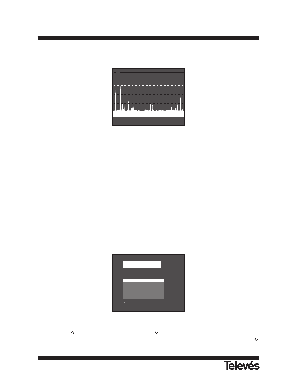
4.10.- Spectrum Analyser Operating Mode
The Spectrum Analyser mode allows the user to discover the signals present in the frequency band in quickly and easily and to make
measurements at the same time. To select it press key SPECT [21]. The monitor will show a picture like the one described in the next figure.
Figure 17.- Spectrum Analyser mode.
The horizontal lines define the signal level, the broken lines being 5 dB from the solid ones. The level of the top line (80 dBµV in previous
figure), named the Reference Level, can be altered using the Reference level function in the Spectrum Analyser mode functions menu
(section 4.10.1.3).
The signal level for each frequency is displayed vertically, the lower frequencies appearing at the left of the screen and the higher ones at
the right. The amplitude of the lobes is calibrated. In the example in previous figure the noise level is at around 37 dBµV and the lobe with the
highest signal level (second from the left) is at 64 dBµV.
The frequency range displayed (called span from hereon) can also be altered using the Spectrum Analyser mode functions menu.
A vertical broken line, called marker, appears on the spectrum display to identify the tuned frequency.
One of the applications of the MTD 120 operating as Spectrum Analyser is in the search for the best orientation and position of the
receiving antenna. This is particularly important in UHF. Because such frequencies are involved, with wavelengths ranging from 35 cm to 65
cm, if the antenna is shifted only a few centimetres, the relationship between the picture, chrominance and sound carrier frequencies change,
affecting the quality of the picture in the receiver.
If there is an excess of sound carrier, tearing or 'moiré' may appear on the screen due to the frequency beats between the sound,
chrominance and the picture frequencies.
If there is a chrominance carrier defect, then the television colour amplifier must function at maximum gain, which could result in noise
appearing all over the television screen with points of colour that disappear when the saturation control is reduced; in an extreme case, loss of
colour may occur.
4.10.1.- Spectrum Analyser Mode Functions Menu
In the Spectrum Analyser operation mode, pressing key ENTER [5] leads you to the next functions menu.
Figure 18.- Spectrum Analyser mode functions menu.
When press key [6] active option moves upwards while press key [6] active option moves downwards.
The downward pointing arrow at the bottom left of the menu means that there are more functions available, to view these press key
[6]. Below we describe the use of each function and its range of values.
FUNCTIONS
Band switching
Span
Reference level
Dual marker
Sweep
Measure bandwidth
80
70
60
50
40
1992.0 MHz 56.9 dBuV
132
TV & SAT Level Meter MTD 120 User Manual
Page 32
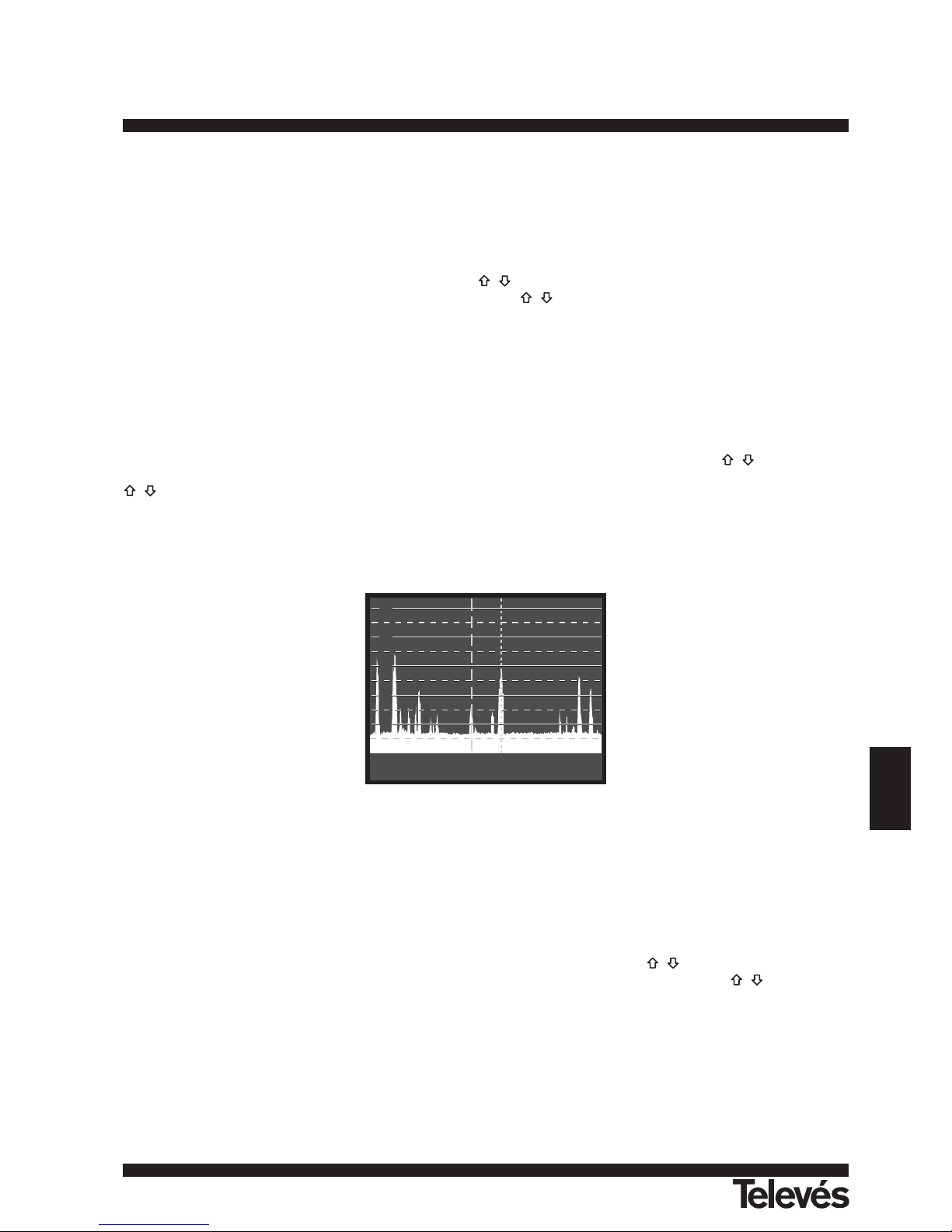
133
ENGLISH
TV & SAT Level Meter MTD 120 User Manual
4.10.1.1.- Band Switching
Permits to swicth from terrestrial (5-862 MHz) to satellite band (920-2150 MHz) and vice versa.
4.10.1.2.- Span
This function enables selecting the displayed frequency range in Spectrum Analyser mode between Full (the entire band), 500 MHz, 200
MHz, 100 MHz, 50 MHz, 32 MHz, 16 MHz and 8 MHz (the latter two only in terrestrial bands).
To alter the span, select the functions menu, then press keys [6] to select the Span function and press key ENTER [5]. The
screen will show a window with the spans which can be selected. Press keys [6] to select the required span and activate it by pressing
key ENTER [5] again.
In Full mode the measuring filter bandwidth used to display the spectrum is always 1 MHz for terrestrial bands, and 4 MHz for satellite
band. For the other spans you can select the bandwidth using the Measure Bandwidthfunction on the same functions menu. (See section
'4.10.1.10 Bandwidth of the Spectrum Measuring Filter').
4.10.1.3.- Reference Level
The reference level corresponds to the level marked by the top horizontal line appearing on the Spectrum Analyser mode screen. This
function enables the reference level to be defined between 70 and 130 dBµV in 10 dB steps. The default reference level is 70 dBµV.
To alter the value of the reference level select the Spectrum Analyser mode functions menu, press keys [6] to select the
Reference level function and press key ENTER [5]. The screen will show a window with the values which can be selected. Press keys
[6] to select the desired reference level and activate it by pressing key ENTER [5] again.
4.10.1.4.- Dual Marker/Single Marker
(Only for level measurements) This function enables two tuning markers (Dual marker) to be seen on the spectrum display. When you
choose this option you can select the active marker (Marker A or Marker B) or return to using only one marker (Single marker).
Figure 19.- Spectrum Analyser mode with two tuning markers.
When you select the Dual marker function, the bottom of the screen displays the frequency of each of the two markers, the signal level
for each frequency and, on the far right, the frequency difference and the level between them.
4.10.1.5.- Sweep
Enables you to choose the sweep speed of the Spectrum mode between High Resolution (slow sweep, high precision) and Fast (fast
sweep, low precision).
To modify the sweep speed select the Spectrum Analyser mode functions menu, then press keys [6] to select the Sweep function
and press key ENTER [5]. The screen will show a window containing all the values which may be chosen. Press keys [6] to select the
desired speed and activate it by pressing key ENTER [5] again.
80
70
60
50
40
MHz : 1460.8
dBuV : 46.4
1632.0
59.4
171.2
13.0
Page 33

134
TV & SAT Level Meter MTD 120 User Manual
4.10.1.6.- Reference Noise
(Only in C/N measurements). Permits to define the frequency where noise level will be measured.
To modify the frequency where you want to measure noise level, accede to the menu functions and select the Reference noise function
then, again in the Spectrum mode, press keys [6] to place the marker on the frequency where you want to measure the noise level or
well, press key SHIFT [31], current reference noise frequency will be erased and using the keyboard introduce the new value. Finally accede
to the functions menu again and execute the Carrier function so that you can tune new carrier frequencies by pressing keys [6] .
4.10.1.7.- Channel Bandwidth
(Only in Channel Power measurements). Permits to define channel bandwidth.
To modify the channel bandwidth, that is to say the power integration limits, accede to the menu functions and select the Channel
bandwidth function then, again in the Spectrum mode, press keys [6] to modify it or well press key SHIFT [31], current channel
bandwidth will be erased and using the keyboard introduce the new value. Finally accede to the functions menu again and execute the
Marker function so that you can tune new carrier frequencies by pressing keys [6] .
4.10.1.8.- Marker
(Only when measuring Channel power and after defining the Channel bandwidth). Permits to change the tuning frequency by means of
keys [6].
4.10.1.9.- Carrier
(Only when measuring C/N Referenced and after defining the Reference noise). Permits to change the tuning frequency by means of
keys [6].
4.10.1.10.- Bandwidth of the Spectrum Measuring Filter (Measure bandwidth)
The frequency resolution of the Spectrum Analyser mode is determined by the bandwidth of the measuring filter when displaying the
spectrum. This parameter is fundamental given the increasing density of channels present in all TV transmission systems.
To alter the bandwidth of measurement select the Spectrum Analyser functions menu, then press keys [6] to select the Measure
bandwidth function and press key ENTER [5]. The screen will show a window displaying the values which can be selected. Pressing keys
[6] to select the chosen bandwidth and activate it by pressing key ENTER [5] again.
The choice of bandwidth is:
Terrestrial channels: 230 kHz or 1 MHz
Satellite channels: 230 kHz or 4 MHz
Filters with the greatest bandwidth (4 MHz y 1 MHz) allow you to take more stable measurements, as well as being able to distinguish
between analogue and digital carriers. The 4 MHz filter is ideal for level measurements on the satellite band. The 230 kHz filter is
recommended for measuring terrestrial television, cable television and MMDS signals. It also allows you to identify smaller bandwidth signals
such as NICAM sound carriers (terrestrial analogue channels), to detect the beacon signal on VSAT, the separation between the audio FM
carrier, and between the stereo sub-carriers in television.
4.10.1.11.- Selecting the Channels Table (Channel set)
See 4.9.2.7 section.
4.10.1.12.- Batteries and External Units Power Supply (Battery & Lnb)
See 4.9.2.3 section.
4.10.1.13.- Exit
Exits from the Spectrum Analyser function menu.
Page 34

135
ENGLISH
TV & SAT Level Meter MTD 120 User Manual
4.10.2.- Selecting the Measurement Mode
The Spectrum Analyser mode permits to make different measurements at the same time you see the signals present in the band. The
types of measurements available are:
Terrestrial band - Analogue channels:
Level Level measurement of the currently tuned carrier.
C/N Video carrier to noise ratio referenced to a noise frequency defi ned by the user through the Reference Noise
function.
Terrestrial band - Digital channels:
Channel power Integration method. It consists of scanning the entire channel, calculating the contribution of each portion of the
spectrum to the whole.
C/N Referenced: Channel level to noise ratio referenced to a noise frequency defined by the user through the Reference
Noise function.
Satellite band - Analogue channels:
Level Level measurement of the currently tuned carrier.
C/N Video carrier to noise ratio referenced to a noise frequency defi ned by the user through the Reference Noise
function.
Satellite band - Digital channels
Channel power Integration method.
C/N Referenced: Channel level to noise ratio referenced to a noise frequency defined by the user through the Reference
Noise function.
Like in the TV mode, to select the type of measure, press key LEVEL [22], then press keys [6] until desired mode is marked and
finally press key ENTER [5] or key LEVEL [22] to activate the new measurement mode.
4.10.2.1.- Measuring Carrier Levels (Level)
(Only for analogue channels). When selecting this mode on the lower part of the image appears the tuned frequency (or channel) and the
signal level at this frequency. If dual marker function is selected, tuned frequency and signal level are showed for each one of the markers
and, on the far right, the frequency difference and the level between them.
4.10.2.2.- Measuring the Carrier / Noise ratio (C/N Referenced)
The Carrier/Noise ratio in Spectrum mode is always referenced to a noise frequency defined by the user.
Imagine a situation like the one shown in the next figure: a digital channel (8 MHz BW) adjacent to an analogue channel. When measuring
C/N for the digital channel in TV mode using the Auto setup, the analogue channel may interfere in the noise measurement (given that the
noise level is measured at f
noise
= f
tuning
- 1/2 Channel BW= 650 MHz - 4 MHz = 646 MHz) so under this situation it is recommended to make
the measurement in Spectrum Analyser mode and to define manually the frequency where we want to measure noise (obviously a
frequency where no signal is present); i.e. in the next figure noise is defined to be measured at 655 MHz.
Page 35
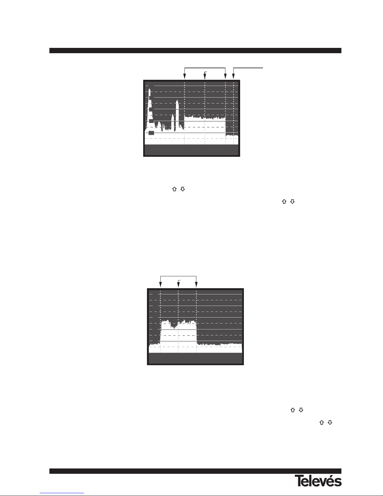
Figure 20.- Carrier to Noise measurement in Spectrum mode (digital channel).
To define the frequency to measure the noise, select the Reference noise function in the Spectrum functions menu and press key
ENTER [5]. Next, again in the Spectrum mode, press keys [6] to place the marker on the frequency where you want to measure noise
level or press key SHIFT [31], current reference noise value will be erased and using the keyboard introduce the new value. Finally accede to
the functions menu again and execute the Carrier function so that you can tune new carrier frequencies by keys [6].
When C/N measuring mode is selected, on the lower part of the image appears the tuned frequency/channel (Carr.), the noise frequency
(Noise), the carrier Level (if analogue mode is selected) or the channel Power (if digital mode is selected) and the carrier to noise ratio (C/N).
4.10.2.3.- Measuring the Power of Digital Channels (Channel Power)
In the Spectrum Analyser mode the MTD 120 measures digital channel power using an Integration method between channel limits
which are defined by the user. To show the interest of this method, imagine a spectral distribution like the one shown in the following figure
(channel bandwidth is 8 MHz defined by the markers). If channel power is measured in TV operation mode different readouts will be obtained
depending on the tuned frequency (measurement filter bandwidth is 230 kHz), if tuning is shifted from 759 MHz to 762 MHz reading will
increase in several dB.
Figure 21.- Channel power measurement in Spectrum Mode.
When measuring Channel power, on the lower part of the image appears the tuned frequency (or channel), the channel bandwidth
(Channel BW) and the Channel Power.
To measure the channel power, first of all it is necessary to define channel bandwidth, that is to say to set the limits of the integration:
select the Channel bandwidth function in the functions menu and then, again in the Spectrum mode, press keys [6] to modify it or
well press key SHIFT [31], current channel bandwidth will be erased and using the keyboard introduce the new value. Finally accede to the
functions menu again and execute the Marker function in order you can tune new carrier frequencies, then when pressing keys [6],
the tuning marker and the channel bandwidth limits will shift together.
80
70
60
50
40
760.00 MHz
Channel Power:
Channel BW: 8.00 MHz
55.0 dBuV
Channel bandwidth
Marker
70
60
50
40
30
Carr.: 650.00 MHz
Power: 44.0 dBuV
Noise: 655.0 MHz
C/N: 12 dB
Channel BW
Carrier
Reference noise
136
TV & SAT Level Meter MTD 120 User Manual
Page 36

137
ENGLISH
TV & SAT Level Meter MTD 120 User Manual
IMPORTANT REMARK
To measure digital channels power correctly it is indispensable to tune channel at its central frequency and to define channel
bandwidth.
4.11.- Selecting the Sound Mode (Sound)
From the TV operating mode, analogue mode, press key SOUND [26]. The screen will show the SOUND menu with the types of sound
available. Pressing keys [6] choose the type of sound you wish and then press key SOUND [26] or the key ENTER [5] to activate it.
Table 4 shows the different options for the sound mode.
Table 4.- Sound modes.
When you select the NTUN (continuous tuning using a narrow detection filter) and BTUN (continuous tuning using a broad detection filter)
options the screen displays a window showing the frequency deviation of the sound carrier, this is variable between 4.00 MHz and 9.00
MHz. To define it press keys [6] to select the desired frequency deviation and press key ENTER [5] to validate.
When the LV function is selected, the speaker of the MTD 120 permits a tone whose frequency depends on the level of the signal
received. This is very useful when installing antennas, since the user can locate the peak signal without having to look continually at the
monitor of the level meter.
When the NICAM option is selected, it is possible to measure the Bit Error Rate of the modulation. To obtain this measurement, from the
TV operating mode, level measurement, press key MONITOR [1] in order to activate the mode of maximum measurement information
displayed on the screen (name assigned to memory, power supply to external units, sound, colour system, TV standard, level and
frequency/channel). In the position relative to the type of Sound will appear the information about the type of NICAM according to:
Sound: Type + Error
Type = NICAM type:
"- -": no NICAM is detected
"du": dual NICAM
"st": stereo NICAM
"mo": mono NICAM
Error = indication of the bit error rate:
"E
v
I": error rate < 1e-5
"E5": 1e-5 < error rate < 1e-4
"E4": 1e-4 < error rate < 1e-3
"E3": 1e-3 < error rate < 2.7 e-3
"E ^I": error rate > 2.7 e-3
Therefore, for example, the indication Sound: duE
v
I has to be interpreted as NICAM sound is selected, the detected NICAM is dual and
Type Function Band
4.50 Sound carrier 4.5 MHz above the picture carrier Terrestrial
5.50 Sound carrier 5.5 MHz above the picture carrier Terrestrial
5.74 Selects the second carrier in DUAL or STEREO transmissions, Terrestrial
at 5.74 MHz of the picture carrier
5.80 Sound carrier 5.8 MHz above the picture carrier Satellite
6.00 Sound carrier 6.0 MHz above the picture carrier Terrestrial
6.50 Sound carrier 6.5 MHz above the picture carrier Terrestrial
Satellite
6.65 Sound carrier 6.65 MHz above the picture carrier Satellite
7.02 Sound carrier 7.02 MHz above the picture carrier Satellite
NTUN Continuous tuning (4.00 - 9.00 MHz) with narrow sound detection filter Terrestrial
(110 kHz) Satellite
BTUN Continuous tuning (4.00 - 9.00 MHz) with broad sound detection filter Terrestrial
(240 kHz) Satellite
NICA NICAM decoding Terrestrial
AM AM demodulation Terrestrial
FM FM demodulation Terrestrial
LV Tone whose frequency varies with the signal level Terrestrial
Satellite
OFF Suppresses the sound Terrestrial
Satellite
Page 37

the error rate is below 1 e-5.
4.12.- Measurement Configuration Memories
To facilitate measurement, the MTD 120 is able to store up to 99 configurations in an internal memory. In this way, it is possible to select
the most common transmissions in a work area with their corresponding configurations quickly and easily.
The following parameters are stored in each configuration: the name assigned to the configuration, frequency or channel number, TV
system, type of measurement, external units supply voltage (VLNB), measurement units and sound parameters.
The different measuring configurations can be retrieved with the Data logger function, in order to conduct different data acquisitions in a
completely automatic way and store them in the memory for later print-out or processing (see paragraph '4.9.2.4 Data logger function').
4.12.1.- Storing a Measurement Configuration (STORE)
The process of storing a measurement configuration is the following:
1. Select the configuration you want on the MTD 120 (freq./channel, band, etc.).
2. Press key MEMORY [25] until the monitor displays the STORE screen. Check the configuration parameters. Then press keys
[6], to select the memory number that you wish to store the configuration in (from 1 to 99). This number corresponds to the column
headings of the Data Logger function.
If a configuration is stored in a memory location already containing information, that data will be lost.
3. (Optional) If you wish to assign a name to a memory position press key SHIFT [31], the first character of the name will blink, press keys
[6] and the different characters will appear in the first position of the configuration name. When you have chosen the first
character press key ENTER [5], to automatically move on to the second character. Repeat the process for a maximum of four
characters.
Figure 22.- STORE screen, storing a measuring configuration.
4. Finally, press key MEMORY [25] or the key ENTER [5] and the configuration will be stored. If any other key is pressed, an error will be
indicated and the memory will not be updated.
4.12.2.- Retrieving a Configuration (RECALL)
Press key MEMORY [25]. The screen RECALL will appear on the monitor which shows the different parameters of each measuring
configuration stored. Pressing keys [6], select the configuration to be retrieved (a number between 1 and 99).
Pressing the key MEMORY [25] again or the key ENTER [5] will retrieve the configuration.
Figure 23.- RECALL screen, retrieving a measurement configuration.
RECALL: C33 1
Channel = 23 (CCIR )
TV Sys = PAL-B/G
Meas = Lv
V Lnb = External
Units = dBuV
Sound = 5.50
STORE: PM01 1
Channel = 23 (CCIR )
TV Sys = PAL-B/G
Meas = Lv
V Lnb = External
Units = dBuV
Sound = 5.50
138
TV & SAT Level Meter MTD 120 User Manual
Page 38
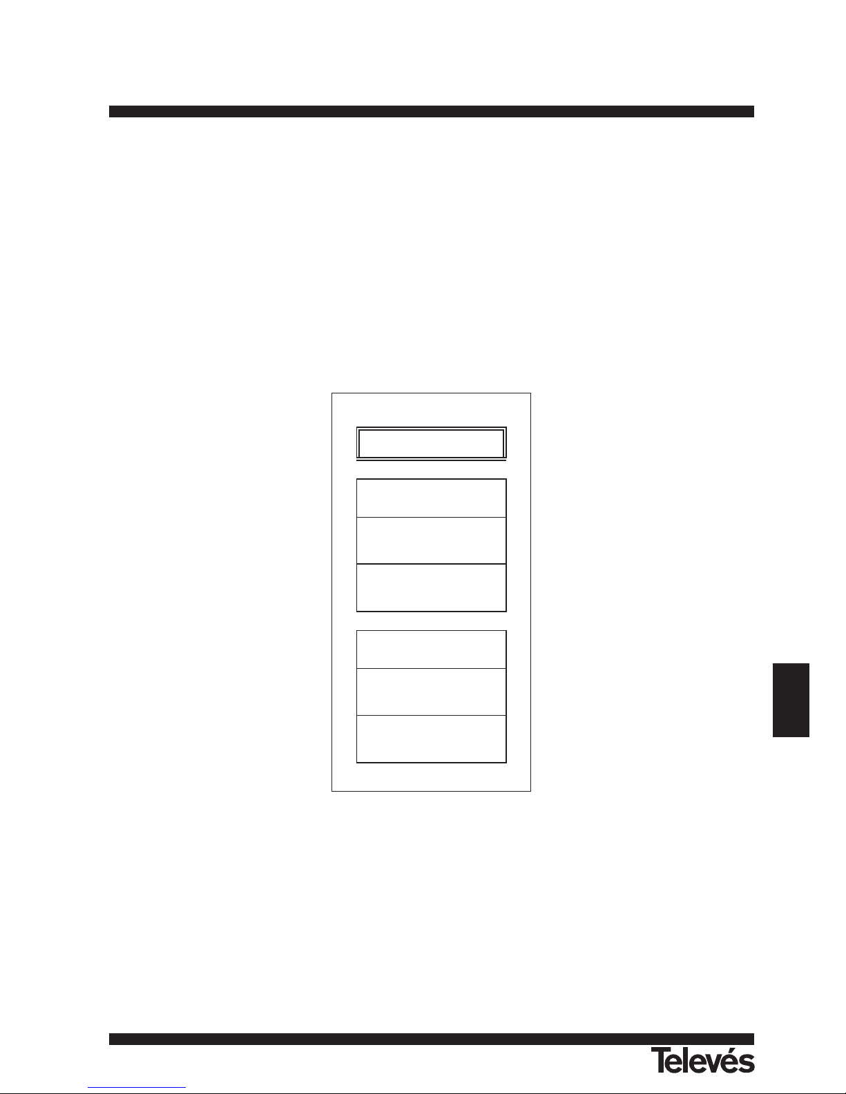
139
ENGLISH
TV & SAT Level Meter MTD 120 User Manual
4.13.- Direct Access to Functions
Keys FA [28] and FB [29] give direct access to any of the functions on the TV and Spectrum Analyser mode functions menus. To
establish a relationship between the direct access key and a function, access the functions menu, select the function you wish to access
directly and press key FA [28] or FB [29]. From then on when you press key FA [28] or FB [29] the function will be accessed directly.
4.14.- Printing Measurements and Memories
By connecting the instrument to a serial printer it is possible to obtain a printed report of a sequence of measurements just at the moment
they are taken, or later, if they are recorded with the Data logger function. This enables the user to keep a file about the state of the system
and provide the documents related to the level measurements for analysis purposes.
The installation process consists of simply using the data transfer cable to connect the printer to the RS-232C connector [37] on the MTD
120 (see section '4.14.1 Handshake and control lines'). Switch off the power to both instruments before connecting.
To print measurements select the Data logger function on the functions menu (see section '4.9.2.4 Data Logger function'), access the
configuration menu, activate the print field (Print: On) and switch on the printer. From now on the printing process is equivalent to taking
measurements.
The following figure shows an example of printing two activated columns (memories 1 PM01 and 2 PM02) and two activated rows (test
points 1 and 2).
Figure 24.- Printing measurements.
LOCATION:
SIGNATURE:
DATE: 01/01/1999
TIME: 08.54.00
TEST POINT: 1
< 1> PM01 Ch 23
Meas.: Lv
Frequency: 487.25 MHz
Level: 69 dBuV
< 2> PM02 Ch -Meas.: Lv
Frequency: 621.25 MHz
Level: 75 dBuV
DATE: 01/01/1999
TIME: 08.55.00
TEST POINT: 2
< 1> PM01 Ch 23
Meas.: Lv
Frequency: 487.25 MHz
Level: 70 dBuV
< 2> PM02 Ch -Meas.: Lv
Frequency: 621.25 MHz
Level: 74 dBuV
Page 39

4.14.1.- Handshake and Control Lines
Next is described the handshake and control lines used by the MTD 120:
- The following parameters are used for printing through the serial port:
Rate: 19.200 bauds
Data bits: 8 bits
Parity: No
Stop bits: 1
- The control lines used are:
- DATA TRANSMIT (pin 3 MTD 120): To send data to the printer.
- CLEAR TO SEND (pin 8 MTD 120): Data transfer control. Data are sent only when this line is active.
- DATA TERMINAL READY (pin 4 MTD 120): This line is permanently active in order to indicate the establishment of the
communication.
Connections
The cable between the MTD 120 and the printer must have the following connections:
Figure 25.- Connector RS-232C MTD 120. Pins numbering.
12345
6789
140
TV & SAT Level Meter MTD 120 User Manual
PC CONNECTOR LEVEL METER CONNECTOR
Type D-25, female Type D-9, female
SHIELD GROUND 1
DATA TRANSMIT 2 2 DATA RECEIVE
DATA RECEIVE 3 3 DATA TRANSMIT
REQUEST TO SEND 4 1 CARRIER DETECT
CTS 5 4 DATA TERM. READY
DATA SET READY 6
GROUND 7 5 GROUND
CARRIER DETECT 8 7 REQUEST TO SEND
DATA TERMINAL READY 20 6 DATA SEND READY
8 CLEAR TO SEND
RING INDICATOR 22 9 RING INDICATOR
Page 40

141
ENGLISH
TV & SAT Level Meter MTD 120 User Manual
5.- BER MEASUREMENT OF QPSK & QAM MODULATED SIGNALS
5.1.- Description
By means of the options BER measurement for DVB-Satellite (QPSK modulation), DVB-Cable signals (QAM modulation) and DVBTerrestrial (COFDM modulation), it is possible to make Bit Error Rate measurements on digital signals. Besides, these options incorporate the
DCI function (DVB Channels Identifier) which provides information on the tuned channel, in this way it is possible to identify it with total
certainty with no need to decode the digital signal.
5.2.- BER measurement mode selection
To select the BER measurement mode:
1) Select the TV operating mode. If present operating mode is the spectrum analyser mode press key SPECT [21].
2) Select the terrestrial band for the measurement of QAM or COFDM modulated signals or the satellite band for the measurement of
QPSK modulated signals.
QAM signals 47 MHz to 862 MHz
QPSK signals 950 MHz to 2150 MHz
COFDM signals 470 to 862 MHz
3) Select the DIGITAL operating mode by means of the key A/D [20].
4) Select the BER measurement mode: to do this press key LEVEL [22], press keys [6] to select the BER measuring mode, next,
to activate it press key ENTER [5] or key LEVEL [22].
5.3.- QAM modulation
Before to measure the BER it is necessary to define some parameters concerning the digital signal, which are described next. To see its
present value or to modify it, being in the BER measuring screen, press key ENTER [5], a multiple-choice menu showing the functions relative
to the BER measurement will appear on the screen:
1) Modulations
It defines the modulation type. When selecting this function and pressing key ENTER [5], a multiple-choice menu will appear on the
screen, this menu permits to choose one of the following modulations: 16, 32, 64, 128 and 256.
2) Symbol Rate
When selecting this function and pressing key ENTER [5], a multiple-choice menu will appear on the screen, this menu permits to choose
one of the following values: 6875, 6111, 5000, 4443, 1528, 1500, 1408, 1333, 1266, 1000 kbauds, or well to define any other value by
means of the Other option.
When selecting the Other option, a screen titled QAM SYMBOL RATE will appear, this screen shows present Symbol Rate value, to
modify it press key SHIFT [31], enter the new value (four figures) and finally press key ENTER [5] to activate it.
3) Spectral Inv.
If necessary, activate the Spectral inversion. If the spectral inversion is not correctly selected, reception will not be correct.
4) Attenuator
It permits to select attenuation between 0 and 30 dB. It is advisable to activate the 30 dB attenuator under that measurement conditions
where the signal level is near to the maximum input level (approximately starting from 20 dB under the maximum level) and it is possible
that the tuner becomes saturated. Under no-saturation conditions, when increasing the attenuation value the BER measure must to
maintain or to increase (insufficient signal level) but never to decrease.
Once you have defined the QAM signal parameters, it will be possible to measure the BER.
When the BER measuring mode is selected, the monitor will show a picture like the following:
Figure 26.- BER measuring screen for QAM modulated signals.
QAM 1.0E-5
BER before FEC
-8 -7 -6 -5 QEF -3 -2
Freq: 800.00 MHz + 1.2kHz
W.P. 0 in 00:22:59
MPEG-2
Page 41
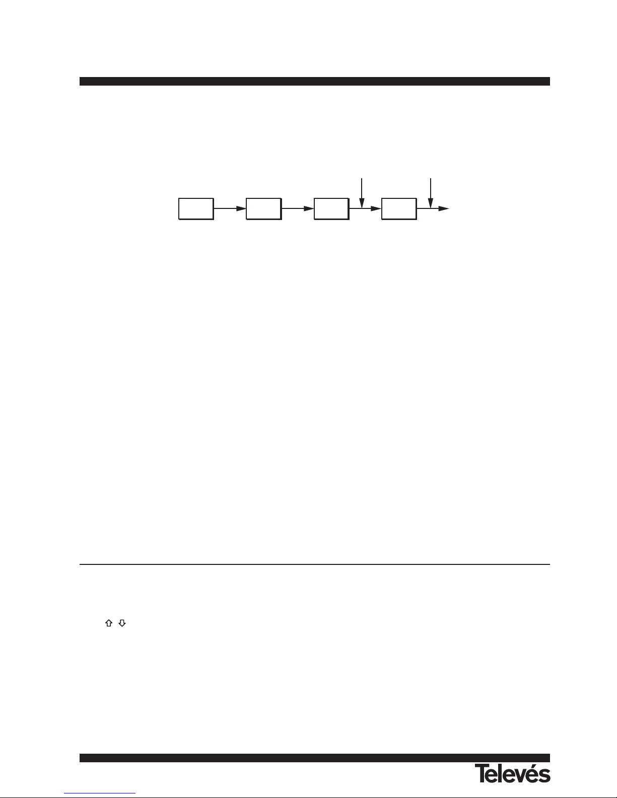
First of all it is shown the BER before FEC (Forward Error Correction).
In a digital reception system for cable signals, after the QAM decoder an error correction method called Reed-Solomon is applied (see
figure 27). Obviously, the error rate after the corrector is lower to the error rate at the QAM decoder output. This is the reason because this
screen provides the BER measurement before FEC (Forward Error Correction) and the number of non correctable errors (W.P., Wrong
Packets) received after Reed-Solomon in the measuring time.
Figure 27.- Digital reception system via cable.
The BER measurement is provided in scientific notation (i.e. 1.0 E-5 means 1.0x10
-5
that is to say one wrong bit of every 100,000) and
through an analogue bar (as its length is smaller the signal quality will be better). The analogue representation is done on a logarithmic scale
(not linear).
With the aim to have a reference about the signal quality, it is considered that a system has a good quality when it decodes less than one
non-correctable error for every transmission hour. This border is known as QEF (Quasi-Error-Free) and it corresponds approximately to a
BER before FEC of 2.0E-4 BER (2.0x10
-4
, that is to say two incorrect bits of every 10,000). This value is marked on the measurement bar of
the BER and therefore, BER for acceptable signals must be at theleft side of this mark.
Below the BER analogue bar it is shown the tuned frequency (or channel) and the frequency deviation in kHz between the tuned
frequency and the one which optimizes the BER (i.e. 800.00 MHz + 1.2 kHz).
In the next line it is shown the number of non corrigible packets received 'wrong packets' (up to a maximum of 126) in the time detailed
on its right. A packet is considered wrong when one, at least, non corrigible bit is detected. To reset this measurement just modify the
measurement conditions: for example change the tuned frequency.
Finally it is shown a status line which displays information about the detected signal. The possible messages that can appear and its
meaning are shown in the following list. The messages are exposed from less to more fulfilment of the MPEG-2 standard:
No signal received
Any signal has been detected.
Signal received
A signal is detected but it can not be decoded.
Carrier recovered
A digital carrier has been detected but it can not be decoded.
MPEG-2
Correct detection of a MPEG-2 signal. The BER is showed.
In case of detecting a DVB signal, message MPEG-2 DVB-C will appear and the DVB Channel Identifier function will be autoatically
activated. See section 5.4.1 DVB Channel Identifier.
IMPORTANT REMARK
DVB-C channels tuning may require an adjusting process. It is recommended to follow next procedure:
1.- From the spectrum analyser mode, tune the channel at its central frequency.
2.- Switch to TV mode, BER measuring mode.
3.- If in the lower line of the screen does not appear MPEG-2 message (and consequently BER is unacceptable), by pressing keys
[6] deviate the tuning frequency until MPEG-2 message appears. Finally tune channel again to minimize the frequency
deviation which optimizes the BER and therefore minimize the BER.
If it is not possible to detect any MPEG-2 channel, make sure that digital signal parameters are correctly defined and if signal level is too
low, check that the 30 dB attenuator is not activated (Attenuator 0 dB).
TUNER
QAM
DEMOD.
A/D
REED-
SOLOMON
BER before FEC Wrong packets
142
TV & SAT Level Meter MTD 120 User Manual
Page 42

143
ENGLISH
TV & SAT Level Meter MTD 120 User Manual
5.4.- QPSK modulation
Before to measure the BER it is necessary to define some parameters concerning the digital signal, which are described next. To see its
present value or to modify it, being in the BER measuring screen, press key ENTER [5], a multiple-choice menu showing the functions relative
to the BER measurement will appear:
1) Code Rate
Also known as Viterbi ratio. It defines the ratio between the number of data bits and actual transmission bits (the difference corresponds to
the control bits for error detection and correction). It permits to choose between 1/2, 2/3, 3/4, 4/5, 5/6, 6/7, 7/8, 8/9 and Auto. If Code
Rate parameter is not known it is possible to assign the Auto option.
2) Symbol Rate
It is possible to choose between the following values: 30000, 27500, 22000, 20000, 19995, 6110, 6000, 5998, 5632, 5062, 4340, 4000
kbauds, or well to define any other value (Other). When selecting the Other option, a screen titled Q PSK SYMBOL RATE will appear.
This screen shows present value, to modify it press key SHIFT [31] and enter the new value through the keyboard. The unit accepts any
number with 5 figures between 2000 and 35000 kbauds (fifth figure acts as validation). For example, to select a symbol rate of 8200
kbauds it must be entered: 08200.
3) Spectral Inv.
Finally, if necessary, activate the Spectral inversion. The Auto mode permits to automate this selection except for the following Code
Rate: 4/5, 5/6, 6/7 and 8/9. If the spectral inversion is not correctly selected, reception will not be correct.
4) Attenuator
It permits to select attenuation between 0 and 30 dB. It is advisable to activate the 30 dB attenuator under that measurement conditions
where the signal level is near to the maximum input level (approximately starting from 20 dB under the maximum level) and it is possible
that the tuner becomes saturated. Under no-saturation conditions, when increasing the attenuation value the BER measure must to
maintain or to increase (insufficient signal level) but never to decrease.
Once you have defined the QPSK signal parameters, it will be possible to measure the BER.
When the BER measuring mode is selected, the monitor will show a picture like the following:
Figure 28.- BER measuring screen for QPSK modulated signals.
Two BER measurements are shown:
1) BER before FEC (Forward Error Corrections)
2) BER after Viterbi
In a digital reception system for satellite signals, after the QPSK decoder two different correction methods are applied (see figure 29).
Obviously, each time we apply an error corrector to a digital signal, the error rate changes, therefore if we measure in a digital satellite
television system, for example, the error rate at the output of the QPSK demodulator, at the output of the Viterbi decoder, and at the output of
the Reed-Solomon decoder, we obtain nothing more than different error rates. This is the reason because the BER measurement is provided
before FEC, after Viterbi and the number of non correctable errors (W.P. - wrong packets-) received after Reed-Solomon for the measuring
time.
Figure 29.- Digital reception system via satellite.
TUNER
QPSK
DEMOD.
DUAL A/D
VITERBI
REED-
SOLOMON
BER before FEC BER after Viterbi Wrong packets
I
Q
QPSK 1.0E-7
BER before FEC: 2.0E-3
-6 -5 -4 -3 -2 -1
BER after Viterbi: 2.0E-3
-8 -7 -6 -5 QEF -3 -2
Freq: 1777.0 + 1.2 MHz
W.P. 0 in 00:22:59
MPEG-2
Page 43

The BER measurement is provided in scientific notation (i.e. 2.0 E-3 means 2.0x10⁻³, that is to say two incorrect bits of every 1,000) and
through an analogue bar (as its length is smaller the signal quality will be better). The analogue representation is done on a logarithmic scale
(not linear).
With the aim to have a reference about the signal quality, it is considered that a system has a good quality when it decodes less than one
non-correctable error for every transmission hour. This border is known as QEF (Quasi-Error-Free) and it corresponds approximately to a
BER after Viterbi of 2.0E-4 BER (2.0x10
-4
). This value is marked on the measurement bar of the BER after Viterbi and therefore, BER for
acceptable signals must be at the left side of this mark.
Next it is shown the tuning frequency and the frequency deviation in MHz between the tuned frequency and the one which optimizes the
BER (i.e. Freq: 1777.0 +1.2 MHz).
Next it is shown the number of non corrigible packets received W.P. -wrong packets- (up to a maximum of 126) in the time detailed on its
right. A packet is considered wrong when a bit is received incorrectly. To reset this measurement just modify the measurement conditions: for
example change the tuning frequency.
Finally it is shown a status line with information about the detected signal. The possible messages that can appear and its meaning are
shown in the following list. The messages are exposed from less to more fulfilment of the MPEG-2 standard:
No signal received
Any signal has been detected.
Signal received
A signal is detected but it can not be decoded.
Carrier recovered
A digital carrier has been detected but it can not be decoded.
Viterbi synchronized
A digital carrier has been detected and the Viterbi algorithm is synchronized, but too many frames arrive with non correctable errors. It is
not possible to quantify the BER.
MPEG-2
Correct detection of a MPEG-2 signal.
In case of detecting a DVB signal, message MPEG-2 DVB-S will appear and the DVB Channel Identifier function will be automatically
activated. See section 5.4.1 DVB Channel Identifier.
IMPORTANT REMARK
DVB-S channels tuning may require an adjusting process. It is recommended to follow next procedure:
1.- From the spectrum analyser mode, tune the channel at its central frequency.
2.- Switch to TV mode, BER measuring mode.
3.- If in the lower line of the screen does not appear MPEG-2 message (and consequently BER is unacceptable), by pressing keys
[6] deviate the tuning frequency until MPEG-2 message appears. Finally tune again channel to minimize the frequency
deviation which optimizes the BER and therefore minimize the BER.
If it is not possible to detect any MPEG-2 channel, make sure that digital signal parameters are correctly defined and if signal level is too
low, check that the 30 dB attenuator is not activated (Attenuator 0 dB).
144
TV & SAT Level Meter MTD 120 User Manual
Page 44

145
ENGLISH
TV & SAT Level Meter MTD 120 User Manual
5.5.- COFDM modulation
Before to measure the BER it is necessary to define some parameters concerning the digital signal, which are described next. To see its
present value or to modify it, being in the BER measuring screen, press the ENTER [5] key, a multiple-choice menu showing the functions
relative to the BER measurement will appear. The parameters that must be defined by the user are the following:
1) Carriers
It defines the number of modulation carriers between 2k and 8k. To modify its value, place the marker over the Carriers field by pressing
keys [6] and then press ENTER [5] key: a menu will appear on the screen. With keys [6] select the desired value for the
Carriers parameter and finally press ENTER [5] key again to validate.
2) Guard interval
The Guard Interval parameter corresponds to the time between symbols, its purpose is to permit a correct detection in multi-path situa-
tions. This parameter is defined according to the symbol length: 1/4, 1/8, 1/16, 1/32. To modify its value, press keys [6] and place
the marker over the Guard Interval field and then press ENTER [5] key: a menu with the available values will appear. Then pressing keys
[6] select the desired value and finally press ENTER[5] key to validate.
3) Attenuator
It permits to select attenuation between 0 and 30 dB. It is advisable to activate the 30 dB attenuator under that measurement conditions
where the signal level is near to the maximum input level (approximately starting from 20 dB under the maximum level) and it is possible
that the tuner becomes saturated. Under no-saturation conditions, when increasing the attenuation value the BER measure must to maintain or to increase (insufficient signal level) but never to decrease.
This configuration menu shows, besides the user definable COFDM signal parameters, the value of the rest of COFDM signal parameters
detected automatically:
Code Rate Also known as Viterbi ratio, defines the ratio between the data bits number and the total number of bits transmitted (the
difference corresponds to the number of control bits for the error detection and recovery).
Modulations Carriers modulation. It also defines the system noise immunity. (QPSK, 16-QAM and 64-QAM).
Spectral Inv. Defines the state of the spectral inversion.
Hierarchy The DVB-T norm contemplates the possibility to make a DTT transmission with hierarchical levels, it is to say a simul-
taneous transmission of the same program with different image qualities and noise protection levels, in order the
receiver decodes the signal in the best conditions.
Once you have defined the COFDM signal parameters, it will be possible to measure the BER. When the BER measuring mode is selec-
ted, the monitor will show a picture like the following:
Figure 30.- COFDM signals BER measuring screen.
Two measures are shown:
1) CSI: Channel status information
2) BER after Viterbi
The CSI measure (Channel Status Information) is a qualitative measure about channel state, between 0 and 100%. The optimum value
corresponds to 0%. This measure permits to look for the best situation even in those measuring conditions where the measured BER is best
than the minimum readout (in this way, in the example of the previous figure, the measured BER is lower that the minimum readout, 1.0x10
-7
,
but the CSI measurement, 27%, still can be improved).
Next it is shown the BER after Viterbi measurement both in numeric and graphic bar format.
In a reception system of terrestrial digital signal, after the COFDM decoder two error correction methods are applied. Obviously, each time
we apply an error corrector to the digital signal, the error rate changes, therefore if we measure the error rate at the output of the COFDM
demodulator, at the output of the Viterbi decoder, and at the output of the Reed-Solomon decoder, we obtain nothing more than different error
rates. This is the reason because of the QPSK-COFDM option provide the BER after Viterbi and the number of Wrong packets received
after Reed- Solomon.
COFDM 1.0E-7
CSI: 27%
0 25 50 75 100
BER after Viterbi:
-7 -6 -5 QEF -3 -2 -1
Chan: 67
W.P. 0 in 00:22:59
MPEG-2 DVB-T
Page 45
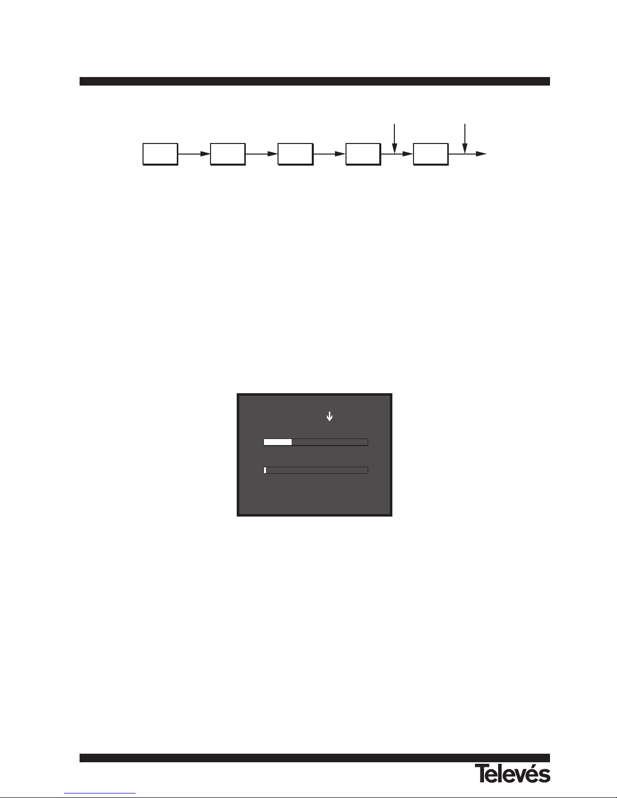
Figure 31.- COFDM reception system.
The BER measurement is provided in scientific notation (i.e. 3.1 E-7 means 3.1x10
-7
, that is to say 3.1 wrong bits of each 10000000) and
through a graphic bar (as its length is smaller the signal quality will be better). The analogue representation is done on a logarithmic scale (not
linear), that is to say, the bar divisions correspond to the exponent of the measurement.
With the aim to have a reference about the signal quality, it is considered that a system has a good quality when it decodes less than one
non-correctable error for every transmission hour. This border is known as QEF (QUASI-ERROR-FREE) and it corresponds approximately to
a BER after Viterbi of 2.0E-4 BER (2.0x10
-4
, that is to say 2 wrong bits of each 10000). This value is marked on the measurement bar of the
BER and therefore, BER for acceptable signals must be at the left side of this mark.
In the lower line of the screen it appears the W. P. counter (Wrong Packets counter). This counter shows the number of wrong packets
received after Reed-Solomon during the measuring time. This counter is automatically activated when the unit detects an MPEG-2 signal.
If at any time, the received signal stops to satisfy the requirements of the MPEG-2 standard, this counter will deactivate, that is to say it
will keep the number of wrong packets received and the measuring time, later, if an MPEG-2 signal is received again, it will activate with no
reset.
When during any measuring time interval the counter has been deactivated, in other words the signal has not satisfied the MPEG-2 requirements, the presentation of this counter will alternate with another counter titled FAIL. This second counter shows the time that the detected
signal has not fulfilled the MPEG-2 standard requirements (12 seconds in the example of the following figure) and the number of signal cuts (2
in the example of the following figure). To reset the counter it is necessary to change any of the detection parameters, for example tune again
the signal or push twice the LEVEL [22] key.
Figure 32.- Signalling two MPEG-2 signal cuts with a total length of 12 seconds.
Finally it is shown a status line with information about the detected signal. The possible messages that can appear and its meaning are
showing the following list. The messages are exposed from less to more fulfilment of the MPEG-2 standard:
No signal received
No signal has been detected.
Timing recovered
Only it is possible to recuperate the symbol time.
AFC in lock
The system automatic frequency control can identify and lock a digital transmission (DTT) but its parameters can not be obtained. It can
be due to a transitory situation previous to the TPS identification (Transmission Parameter Signalling) or well to a DTT transmission with
an insufficient C/N ratio.
COFDM 1.0E-7
CSI: 27%
0 25 50 75 100
BER after Viterbi:
-7 -6 -5 QEF -3 -2 -1
Chan: 67
FAIL 00:00:12 ( 2)
MPEG-2 DVB-T
TUNER
COFDM
DEMOD.
A/D
VITERBI
REED-
SOLOMON
BER after Viterbi Wrong packets
146
TV & SAT Level Meter MTD 120 User Manual
Page 46

147
ENGLISH
TV & SAT Level Meter MTD 120 User Manual
TPS in lock
The TPS (Transmission Parameter Signalling) are decoded. The TPS are carriers (17 in the 2k system and 68 in the 8k system) modula-
ted in DBPSK, containing information related to the transmission, modulation and codification: Modulation type (QPSK, 16-QAM, 64-
QAM), Hierarchy, Guard Interval, Viterbi Code Rate, Transmission mode (2k or 8k) and Number of the received frame.
MPEG-2
Correct detection of a MPEG-2 signal.
In case of detecting a DVB signal, message MPEG-2 DVB-T will appear and the DVB Channel Identifier function will be automatically
activated. See section 5.6. DVB Channel Identifier.
Page 47
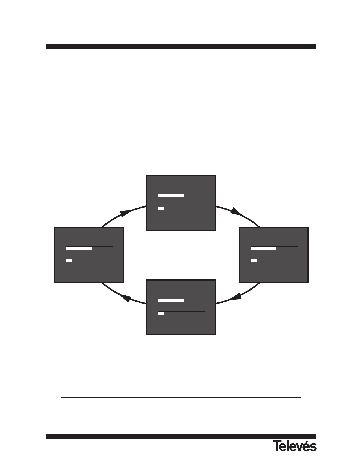
5.6.- DVB Channels Identifier: DCI function
This function permits to identify DVB channels with no need to have a digital signal decoder which permits to see transmitted TV
channels.
The DVB group recommends to digital TV service operators the codification on the Transport Stream of some particular fields containing
data information. The Transport Stream is a sequence of packets, of constant length, which carry video or audio information or data.
Data packets can be grouped to constitute TABLES, some of these tables content information defined by the network operator and which
show the type of service that is being supplied to the users. Among the different data defined in these tables, the most frequently used data
for channel identification purposes are:
Network It contents the name given to the set of all the Transport Stream managed inside the same communication channel.
Bouquet It contents the name given to the set of all the services commercialized as one entity.
Service It contents the names of services that, under the control of one operator, can be shown at each moment on the
Transport Stream, as a function of current programming.
In case the operator includes this information, the three fields are not transmitted at the same time but they appear alternatively in
different packets. Besides, the cadence of presentation of each one of these packets may vary from one operator to another.
When tuning a DVB compatible transponder, the DCI function (DVB Channels Identifier) detects those data packets including service
information relative to these three fields and shows on the lower line on the screen the information contained in them automatically.
Figure 33.- DCI function. In this example the information coded by the operator on the
Service and Network fields is the same.
The information that appears in the Network, Bouquet and Service fields is responsibility of the Operator in charge
of the tuned transponder. The MTD 120 only decodes this information, if it is present, and shows it on the screen.
QPSK 1.0E-7
BER before FEC: 1.0E-3
-6 -5 -4 -3 -2 -1
BER after Viterbi: 1.0E-7
-8 -7 -6 -5 QEF -3 -2
Freq: 1224.0 - 0,8 MHz
W.P. 0 in 00:22:59
MPEG-2 DVB-S
QPSK 1.0E-7
BER before FEC: 1.0E-3
-6 -5 -4 -3 -2 -1
BER after Viterbi: 1.0E-7
-8 -7 -6 -5 QEF -3 -2
Freq: 1224.0 - 0,8 MHz
W.P. 0 in 00:23:22
Bouquet: News Bouquet
QPSK 1.0E-7
BER before FEC: 1.0E-3
-6 -5 -4 -3 -2 -1
BER after Viterbi: 1.0E-7
-8 -7 -6 -5 QEF -3 -2
Freq: 1224.0 - 0,8 MHz
W.P. 0 in 00:23:15
Network: NetMed
QPSK 1.0E-7
BER before FEC: 1.0E-3
-6 -5 -4 -3 -2 -1
BER after Viterbi: 1.0E-7
-8 -7 -6 -5 QEF -3 -2
Freq: 1224.0 - 0,8 MHz
W.P. 0 in 00:23:48
Service: NetMed
148
TV & SAT Level Meter MTD 120 User Manual
Page 48

149
ENGLISH
TV & SAT Level Meter MTD 120 User Manual
6.- DESCRIPTION OF THE INPUTS AND OUTPUTS
6.1.- RF input
The RF input is through the RF [35] connector on the side panel. The peak signal level should never exceed 130 dBµV.
6.2.- RS-232C serial port
The MTD 120 incorporates an RS-232C serial port for data exchange with a PC, a serial printer or to other devices. The signals in this
connector are described in Table 5.
Figure 34.- RS-232C connector. External view.
PIN No. SIGNAL CHARACTERISTICS
1 Carrier Detect (not connected)
2 Data Request (RxD)
3 Data Transmit (TxD)
4 Data Transmission Ready (DTR) Fixed at +12 V
5 Ground (GND)
6 Data Send Ready (DSR) (not connected)
7 Request To Send (RTS)
8 Clear To Send (CTS)
9 Ring Indicator (not connected)
Table 5.- Description of the RS-232C connector.
1
2
3
4
5
6
7
8
9
Page 49
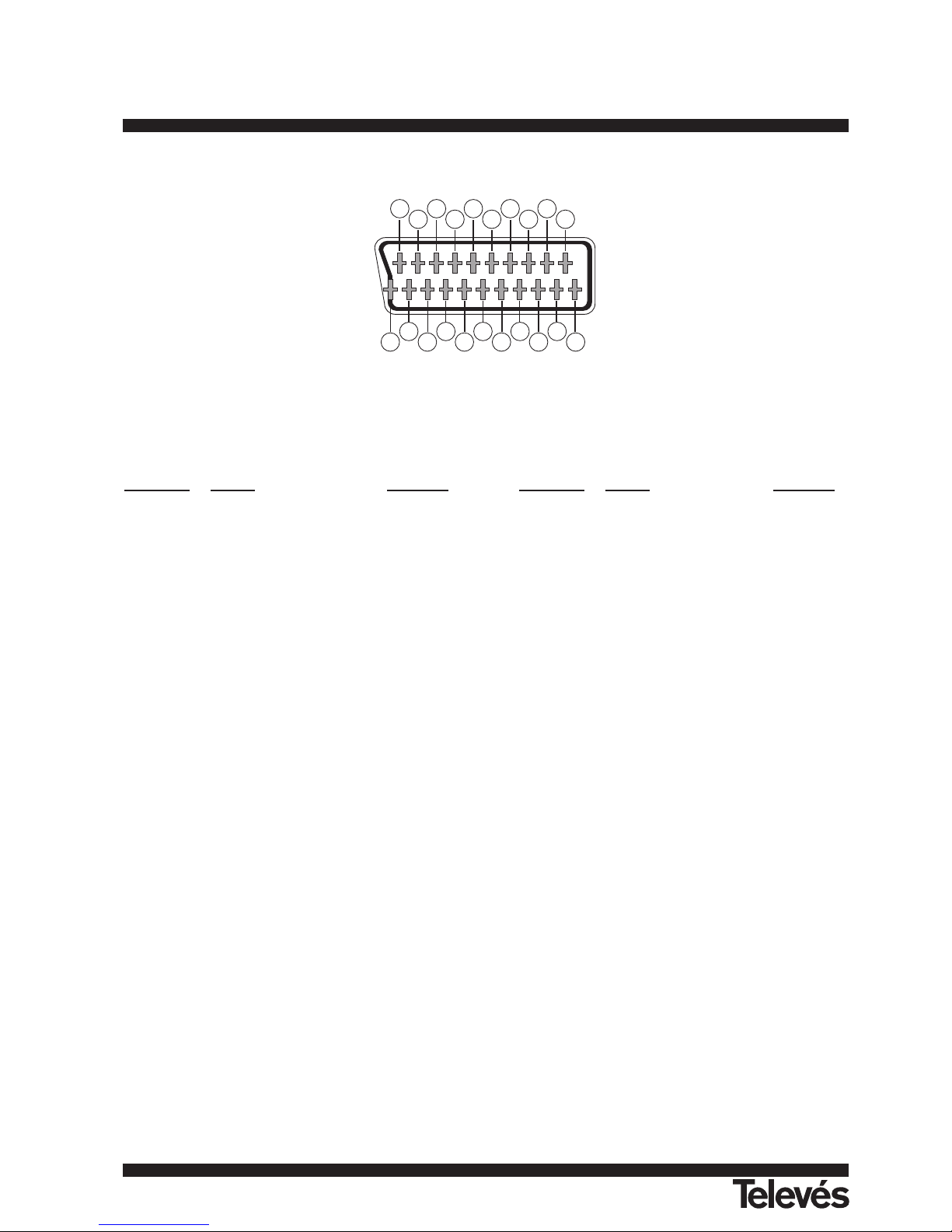
6.3.- Scart (DIN EN 50049)
Figure 35.- Scart socket (external view).
Also known as PERITEL connector (in conformity with standard NF-C92250). The signals in this connector are the following:
PIN number
SIGNAL CHARACT. PIN number SIGNAL CHARACT.
1 Right channel audio output 12 Digital bus interface (not connected)
2 Right channel audio input 13 Red grounding (R)
3 Left channel audio output 14 Digital bus reserved (not connected)
4 Audio grounding 15 Red output (R)
5 Blue grounding (B) 16 Blanked signal (not connected)
6 Left channel audio input 17 Composite video grounding
7 Blue output (B) 18 Blanked return (not connected)
8 Switching voltage 19 Composite video output
9 Green grounding (G) 20 Video input
10 Digital bus interface (not connected) 21 Connector shield grounding
11 Green output (G)
Table 6.- Description of the Scart.
201816
14
12
1086
4
2
1
3
5
7
9
11
13
15
17
19
21
150
TV & SAT Level Meter MTD 120 User Manual
Page 50
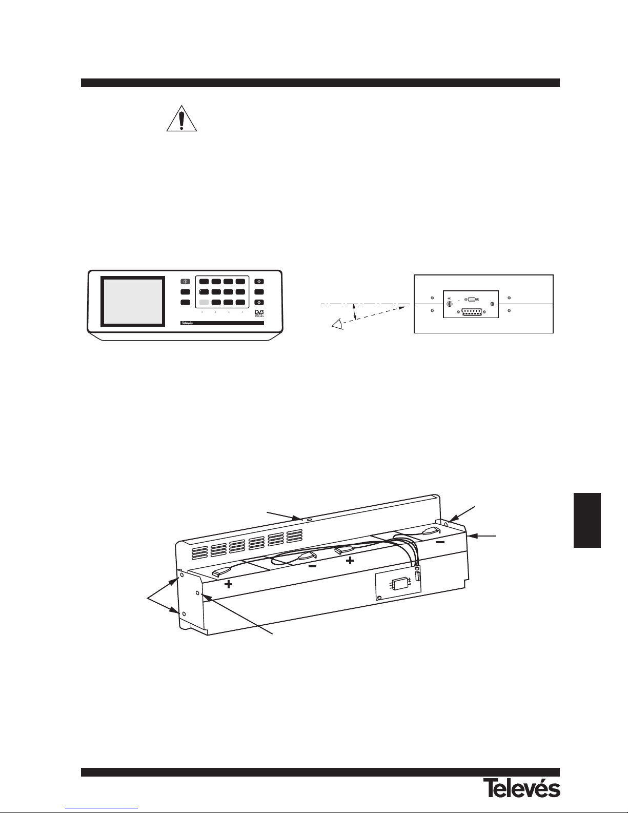
151
ENGLISH
TV & SAT Level Meter MTD 120 User Manual
7.- MAINTENANCE
7.1.- Considerations about the Screen (only ref. 4202)
This paragraph offers key considerations regarding the use of the colour screen, taken from the specifications of the manufacturer.
In the LCD display, the user may find pixels that do not light up or pixels that are permanently lit. This should not be regarded as a defect
in the LCD. In accordance with the manufacturer quality standard, 9 pixels with these characteristics are considered admissible.
Pixels which are not detected when the distance from the surface of the LCD screen to the human eye is greater than 35 cm, with a
viewing angle of 90º between the eye and the screen should not be considered manufacturing defects either.
It is advisable a viewing angle of 15º in the 6.00 o'clock direction in order to obtain the optimum visualization of the screen. See following
figure.
Figure 36.- Optimum viewing of the screen.
7.2.- Internal fuses which user cannot replace
The following fuses are found on the base board. Their location identifier and characteristics are the following:
F4 & F5 5 A F 63 V SMD
F3 1 A F 63 V SMD
7.3.- Replacing the Batteries
Batteries must be replaced whenever the capacity of the fully-charged batteries is noticeably diminished. To change the batteries, follow
next procedure:
Figure 37.- Battery compartment.
- Remove the rear holster, if in place.
- The battery compartment is located in the rear panel of the instrument. Remove the 5 securing screws (A) (2 on each side and 1 at the
bottom) shown in the previous figure (here the battery compartment is shown taken out and facing down). Rest the MTD 120 on its rear
panel and lift it to free the battery compartment.
- Remove the 2 side screws (C) securing the battery holder (B).
- Disconnect the battery terminals, remove the anti-humidity paper and replace the batteries with two new ones of the same type.
A
B
C
A
A
C
RST
RS-232C
SCART ITF
EXT.
SUPPLY
BATTERY OK CHARGER
EXT VIDEO
DRAIN
MONITOR
SCREEN
A/D
0
SHIFT
CH/F
SPECT
1
7
LEVEL
2
FA
8
MODE
3
FB
9
SEARCH4MEMORY
5
LNB
6
SOUND
Medidor de Campo Color TV&SAT MTD 120
ENTER
15°
Page 51
IMPORTANT
The maximum period of time that the instrument can remain disconnected from the batteries before loosing measurement
configurations and stored data is 5 minutes.
- Replace the anti-humidity paper and connect the terminals to the new batteries. Remember to maintain the polarity of the terminals:
red-positive, black-negative.
WARNING
Avoid any type of short circuit among the cables connected to the battery, since the resulting high current may cause serious
damage to the instrument.
- Place and secure the battery holder (B) with the two screws (C).
- Insert the battery compartment into the back of the MTD 120 and secure with the five screws (A).
- If you wish, replace the holster.
7.4.- Cleaning Recommendations
The cover should be cleaned by means of a light solution of detergent and water applied with a soft cloth.
Dry thoroughly before using the system again.
CAUTION
Do not use for the cleaning of the front panel and particularly the viewfinders, alcohol
or its derivatives, these products can attack the mechanical properties of the materials
and diminish their useful time of life.
CAUTION
To clean the cover, take care the instrument is disconnected.
Do not use scented hydrocarbons or chlorized solvents.
Such products may attack the plastics used in the construction of the cover.
152
TV & SAT Level Meter MTD 120 User Manual
Page 52
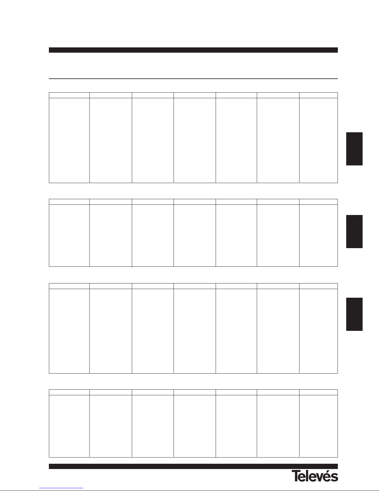
ESPAÑOL
FRANÇAIS
ENGLISH
Ch. Freq.
2 48,25
3 55,25
4 62,25
S01 105,25
S02 112,25
S03 119,25
S04 126,25
S05 133,25
S06 140,25
S07 147,25
S08 154,25
S09 161,25
S10 168,25
5 175,25
6 182,25
Ch. Freq.
7 189,25
8 196,25
9 203,25
10 210,25
11 217,25
12 224,25
S11 231,25
S12 238,25
S13 245,25
S14 252,25
S15 259,25
S16 266,25
S17 273,25
S18 280,25
S19 287,25
Ch. Freq.
S20 294,25
S21 303,25
S22 311,25
S23 319,25
S24 327,25
S25 335,25
S26 343,25
S27 351,25
S28 359,25
S29 367,25
S30 375,25
S31 383,25
S32 391,25
S33 399,25
S34 407,25
Ch. Freq.
S35 415,25
S36 423,25
S37 431,25
S38 439,25
S39 447,25
S40 455,25
S41 463,25
21 471,25
22 479,25
23 487,25
24 495,25
25 503,25
26 511,25
27 519,25
28 527,25
Ch. Freq.
29 535,25
30 543,25
31 551,25
32 559,25
33 567,25
34 575,25
35 583,25
36 591,25
37 599,25
38 607,25
39 615,25
40 623,25
41 631,25
42 639,25
43 647,25
Ch. Freq.
44 655,25
45 663,25
46 671,25
47 679,25
48 687,25
49 695,25
50 703,25
51 711,25
52 719,25
53 727,25
54 735,25
55 743,25
56 751,25
57 759,25
58 767,25
Ch. Freq.
59 775,25
60 783,25
61 791,25
62 799,25
63 807,25
64 815,25
65 823,25
66 831,25
67 839,25
68 847,25
69 855,25
MTD 120
153
Ch. Freq.
FA 47,75
FB 55,75
FC1 60,50
FC 63,75
5 176
6 184
7 192
8 200
9 208
10 216
11 224
Ch. Freq.
12 232
13 240
14 288
D01 303,25
D02 315,25
D03 327,25
D04 339,25
D05 351,25
D06 363,25
D07 375,25
D08 387,25
Ch. Freq.
D09 399,25
21 471,25
22 479,25
23 487,25
24 495,25
25 503,25
26 511,25
27 519,25
28 527,25
29 535,25
30 543,25
Ch. Freq.
31 551,25
32 559,25
33 567,25
34 575,25
35 583,25
36 591,25
37 599,25
38 607,25
39 615,25
40 623,25
41 631,25
Ch. Freq.
42 639,25
43 647,25
44 655,25
45 663,25
46 671,25
47 679,25
48 687,25
49 695,25
50 703,25
51 711,25
52 719,25
Ch. Freq.
53 727,25
54 735,25
55 743,25
56 751,25
57 759,25
58 767,25
59 775,25
60 783,25
61 791,25
62 799,25
63 807,25
Ch. Freq.
64 815,25
65 823,25
66 831,25
67 839,25
68 847,25
69 855,25
Ch. Freq.
1 49,75
2 59,25
3 77,25
4 85,25
5 93,25
SK1 111,25
SK2 119,25
SK3 127,25
SK4 135,25
SK5 143,25
SK6 151,25
SK7 159,25
SK8 167,25
6 175,25
7 183,25
Ch. Freq.
8 191,25
9 199,25
10 207,25
11 215,25
12 223,25
SK11 231,25
SK12 239,25
SK13 247,25
SK14 255,25
SK15 263,25
SK16 271,25
SK17 279,25
SK18 287,25
S19 295,25
S20 303,25
Ch. Freq.
S21 311,25
S22 319,25
S23 327,25
S24 335,25
S25 343,25
S26 351,25
S27 359,25
S28 367,25
S29 375,25
S30 383,25
S31 391,25
S32 399,25
S33 407,25
S34 415,25
S35 423,25
Ch. Freq.
S36 431,25
S37 439,25
S38 447,25
S39 455,25
S40 463,25
21 471,25
22 479,25
23 487,25
24 495,25
25 503,25
26 511,25
27 519,25
28 527,25
29 535,25
30 543,25
Ch. Freq.
31 551,25
32 559,25
33 567,25
34 575,25
35 583,25
36 591,25
37 599,25
38 607,25
39 615,25
40 623,25
41 631,25
42 639,25
43 647,25
44 655,25
45 663,25
Ch. Freq.
46 671,25
47 679,25
48 687,25
49 695,25
50 703,25
51 711,25
52 719,25
53 727,25
54 735,25
55 743,25
56 751,25
57 759,25
58 767,25
59 775,25
60 783,25
Ch. Freq.
61 791,25
62 799,25
63 807,25
64 815,25
65 823,25
66 831,25
67 839,25
68 847,25
69 855,25
Ch. Freq.
A02 55,25
A03 61,25
A04 67,25
A05 77,25
A06 83,25
A07 175,25
A08 181,25
A09 187,25
A10 193,25
A11 199,25
A12 205,25
Ch. Freq.
A13 211,25
14 471,25
15 477,25
16 483,25
17 489,25
18 495,25
19 501,25
20 507,25
21 513,25
22 519,25
23 525,25
Ch. Freq.
24 531,25
25 537,25
26 543,25
27 549,25
28 555,25
29 561,25
30 567,25
31 573,25
32 579,25
33 585,25
34 591,25
Ch. Freq.
35 597,25
36 603,25
37 609,25
38 615,25
39 621,25
40 627,25
41 633,25
42 639,25
43 645,25
44 651,25
45 657,25
Ch. Freq.
46 663,25
47 669,25
48 675,25
49 681,25
50 687,25
51 693,25
52 699,25
53 705,25
54 711,25
55 717,25
56 723,25
Ch. Freq.
57 729,25
58 735,25
59 741,25
60 747,25
61 753,25
62 759,25
63 765,25
64 771,25
65 777,25
66 783,25
67 789,25
Ch. Freq.
68 795,25
69 801,25
70 807,25
71 813,25
72 819,25
73 825,25
74 831,25
75 837,25
76 843,25
77 849,25
78 855,25
C C I R
S T D L
O I R T
F C C
APENDICE A .- Tablas Canal - Frecuencia
APPENDICE A: Tables Canal-Fréquence
APPENDIX A: Channel - Frequency tables
Page 53

MTD 120
154
ASTRA-HL
ASTRA-VL
ASTRA-HH
ASTRA-VH
Ch. Freq.
49 10714,25
51 10743,75
53 10773,25
55 10802,75
57 10832,25
Ch. Freq.
59 10861,75
61 10891,25
63 10920,75
33 10964,25
35 10993,75
Ch. Freq.
37 11023,25
39 11052,75
41 11082,25
43 11111,75
45 11141,25
Ch. Freq.
47 11170,75
1 11214,25
3 11243,75
5 11273,25
7 11302,75
Ch. Freq.
9 11332,25
11 11361,75
13 11391,25
15 11420,75
17 11464,25
Ch. Freq.
19 11493.75
21 11523,25
23 11552,75
25 11582,25
27 11611,75
Ch. Freq.
29 11641,25
31 11670,75
Ch. Freq.
50 10729,00
52 10758,50
54 10788,00
56 10817,50
58 10847,00
Ch. Freq.
60 10876,50
62 10906,00
64 10935,50
34 10979,00
36 11008,50
Ch. Freq.
38 11038,00
40 11067,50
42 11097,00
44 11126,50
46 11156,00
Ch. Freq.
48 11185,50
2 11229,00
4 11258,50
6 11288,00
8 11317,50
Ch. Freq.
10 11347,00
12 11376,50
14 11406,00
16 11435,50
18 11479,00
Ch. Freq.
20 11508,50
22 11538,00
24 11567,50
26 11597,00
28 11626,50
Ch. Freq.
30 11656,00
32 11685,50
Ch. Freq.
65 11720
67 11758
69 11798
71 11837
Ch. Freq.
73 11876
75 11914
77 11954
79 11992
Ch. Freq.
81 12032
83 12070
85 12110
87 12148
Ch. Freq.
89 12188
91 12226
93 12266
95 12304
Ch. Freq.
97 12344
99 12382
101 12422
103 12460
Ch. Freq.
105 12515
107 12545
109 12574
111 12604
Ch. Freq.
113 12633
115 12663
117 12692
119 12722
Ch. Freq.
66 11740
68 11778
70 11817
72 11856
Ch. Freq.
74 11895
76 11934
78 11973
80 12012
Ch. Freq.
82 12051
84 12090
86 12129
88 12168
Ch. Freq.
90 12207
92 12246
94 12285
96 12324
Ch. Freq.
98 12363
100 12402
102 12441
104 12480
Ch. Freq.
106 12522
108 12552
110 12581
112 12610
Ch. Freq.
114 12640
116 12670
118 12699
120 12728
EUT13-HL
Ch. Freq.
111 10722
113 10775
115 10815
117 10853
Ch. Freq.
119 10892
121D 10914
121A 10933
123 10974
Ch. Freq.
125 11009
127 11054
129 11095
131 11148
Ch. Freq.
131b 11178
1D 11205
1A 11224
3 11265
Ch. Freq.
5 11304
7 11348
9D 11371
9A 11389
Ch. Freq.
11D 11413
11A 11431
13 11474
15 11516
Ch. Freq.
153 11566
155 11604
157 11642
EUT13-VL
Ch. Freq.
110 10719
112 10758
114 10796
116 10834
118 10873
Ch. Freq.
120 10911
122 10949
124 10989
126 11033
128 11079
Ch. Freq.
130A 11113
130D 11131
132A 11163
132D 11196
2 11241
Ch. Freq.
4 11280
4b 11283
6A 11321
6D 11339
8 11363
Ch. Freq.
10A 11404
10D 11422
12A 11446
12D 11446,10
14 11492
Ch. Freq.
16 11531
154 11585
156 11623
158 11662
EUT13-HH
Ch. Freq.
159 11681
51 11745
53 11785
55 11823
57 11862
Ch. Freq.
59 11900
61 11938
63 11977
65 12015
67 12053
Ch. Freq.
69 12092
71 12130
73 12168
75 12203
75b 12211
Ch. Freq.
77 12245
79 12284
81 12322
83 12360
85 12399
Ch. Freq.
87 12437
89 12476
91 12539
93 12565
93b 12573
Ch. Freq.
93c 12583
93d 12590
95 12615
97 12654
99 12692
Ch. Freq.
101 12735
EUT13-VH
Ch. Freq.
50 11727
52 11766
54 11804
56 11843
Ch. Freq.
58 11881
60 11919
62 11958
64 11996
Ch. Freq.
66 12034
68 12073
70 12111
72 12149
Ch. Freq.
74 12188
76 12226
78 12265
80 12303
Ch. Freq.
82 12341
84 12380
86 12418
88 12460
Ch. Freq.
90 12520
92 12558
94 12597
96 12634
Ch. Freq.
98 12673
100 12713
Page 54

A CORUÑA
SANTIAGO
VIGO
VALENCIA
OPORTO
LISBOA
MADRID
ZARAGOZA
BILBAO
BARCELONA
MURCIA
MALAGA
SEVILLA
OVIEDO
LUGO
OURENSE
CANTABRIA
GUIPUZCOA
LEON
BURGOS
ALAVA
NAVARRA
LA RIOJA
HUESCA
TARRAGONA
SEGOVIA
GUADALAJARA
AVILA
CUENCA
TOLEDO
CIUDAD REAL
TERUEL
CASTELLON
BADAJOZ
CORDOBA
HUELVA
CADIZ
JAEN
GRANADA
ALMERIA
ALBACETE
ALICANTE
SALAMANCA
PALENCIA
ZAMORA
VALLADOLID
GIRONA
PALMA DE
MALLORCA
BALEARES
CANARIAS
TENERIFE
LAS PALMAS
SUCURSALES
DELEGACIONES
FABRICAS
SORIA
CACERES
ZAMORA N
DELEGACIONES
ALMERIA C.P. 04008
Campogrís 9.
Tfno. 950 23 14 43
Fax 950 23 14 43
[email protected]
BADAJOZ C.P. 06010
Jacobo Rodriguez Pereira 11
Oficina.
Tfno. 924 20 74 83
Fax. 924 20 01 15
[email protected]
BURGOS C.P. 09080
C/ Juan Vazquez 32.
Tfno. 947 22 78 47 / 909 41 91 95
Fax 947 21 07 31
CACERES C.P.10005
Residencial San Francisco
Blq.1 1ºD.
Tfno. 927 23 14 56 / 900 40 25 00
Fax. 927 23 17 29
CORDOBA C.P. 14012
C/Sta. Rafaela Mª del
Sagrado Corazon 2.
Tfno. 957 27 09 80 / 919 55 55 73
Fax 957 40 30 44
GRANADA C.P. 18008
C/ Alhamí 16. Bajo
Tfno. 958 81 22 81 / 908 95 83 32
Fax 958 81 22 81
[email protected]
JAEN C.P. 23007
Hermanos Pinzón 8.
Tfno. 953 29 50 40 / 953 29 52 21
639 98 44 89
Fax 953 29 52 10
LA RIOJA C.P. 26004
San Prudencio 19. bajo
Tfno. 941 23 35 24
Fax 941 25 50 78
MALAGA C.P.29004
Polígono de Santa Bárbara
C/ Fidias 13.
Tfno. 95 223 98 81
Fax 95 217 37 30
[email protected]
NAVARRA C.P.(Pamplona) 31007
Avda. Sancho el Fuerte 9.
Tfno. 948 27 35 10
Fax 948 17 41 49
[email protected]
OVIEDO C.P.33006
Avda. Buenavista 16.
Tfno. 98 524 43 33
Fax 98 524 41 44
GIRONA C.P. 17190 (Salt)
Ramón Sambola. 9º Ent. 1ª.
Tfno. 972 23 25 43 / 907 23 88 40
PALMA DE MALLORCA C.P. 07007
Ferrer de Pallares 45. bajo D.
Tfno. 971 24 70 02
Fax 971 24 53 42
SALAMANCA
ZAMORA
VALLADOLID C.P. 47008
C/ Arrecife 12.
Tfno. 983 22 36 66
Fax 983 22 36 66
HUESCA
ZARAGOZA C.P. 50002
C/ Monasterio de Alahón 1-3.
Tfno. 976 41 12 73
Fax 976 59 86 86
TELEVES ELECTRONICA
PORTUGUESA
MAIA - OPORTO
Via . Dr Francisco Sa Carneiro. Lote 17.
ZONA Ind. MAIA 1. Sector-X MAIA.
C.P. 4470 BARCA
Tfno. 351 2 9418313
Fax 351 2 9488719/9416180
E-mail: [email protected]
LISBOA
C.P. 1000 Rua Augusto Gil 21-A.
Tfno. 351 1 7932537
Fax 351 1 7932418
E-mail: [email protected]
TELEVES UNITED
KINGDOM LTD
Unit 11 Hill Street, Industrial State
CWMBRAN, GWENT NP44 7PG.
(United Kingdom)
Tfno. 44 01 633 87 58 21
Fax 44 01 633 86 63 11
E-mail: [email protected]
TELEVES FRANCE S.A.R.L.
Parc des Arpents
12 Rue du Pré des Aulnes.
77340 PONTAULT-COMBAULT.(France)
Tfno. 33 01 60 18 30 40.
Fax 33 01 60 18 30 49.
E-mail [email protected]
TELEVES MIDDLE EAST FZE
P.O. Box 17199
JEBEL ALI FREE ZONE DUBAI
UNITED ARAB EMIRATES
Tel. 971 4834 344
Fax. 971 4834 644
E-mail [email protected]
SUCURSALES
BARCELONA C.P. 08940
C/ Sant Ferrán, 27
Cornellá - Barcelona
Telfs. 93 377 08 62 / 93 474 29 50
Fax 93 474 50 06
E-mail [email protected]
BILBAO C.P. 48002
Mendipe 12.
Tfnos. 94 421 50 44 / 443 80 66
Fax 94 444 89 92
[email protected]
A CORUÑA C.P. 15011
Gregorio Hernández 8.
Tfnos. 981 27 47 31 / 27 22 10
Fax 981 27 16 11
[email protected]
LAS PALMAS C.P. 35006
Gral. Mas de Gaminde 26.
Tfnos. 928 23 11 22 / 23 12 42
Fax 928 23 13 66
[email protected]
MADRID C.P. 28005
Paseo de los Pontones 11.
Tfnos. 91 474 52 21 / 474 52 22
Fax 91 474 54 21
[email protected]
MURCIA C.P. 30010
Polígono Conver - C/ Rio Pliego 22.
Tfnos. 968 26 31 44 / 26 31 77
Fax 968 25 25 76
[email protected]
SEVILLA C.P. 41008
Pol. Ind. Store - C/ A-6. Nave 5
Tfnos. 95 443 64 50 / 443 58 00
Fax 95 443 96 93
[email protected]
TENERIFE C.P. 38108
Avda. El Paso, 25 - Los Majuelos
La Laguna.
Tfnos. 922 31 13 14 / 31 13 16
Fax 922 31 13 33
[email protected]
VALENCIA C.P. 46021
Avda. del Puerto 21.
Tfnos. 96 337 12 01 / 337 12 72
Fax 96 337 06 98
[email protected]
VIGO C.P. 36204
Escultor Gregorio Fernández, 5
Tfnos. 986 42 33 87 / 42 40 44
Fax 986 42 37 94
[email protected]
ER 224/1/94
SEDE CENTRAL
SANTIAGO DE COMPOSTELA C.P. 15706
Rúa B. de Conxo, 17
Tfno. 981 52 22 00
Fax 981 52 22 62
Apartado 444
E-mail: [email protected]
www.televes.com
103136/1 - 0-03
 Loading...